Embed Size (px)
Citation preview
Practical use of Ethernet OAMJoerg Ammon ([email protected])Systems Engineer Service Provider
May 2011
© 2011 Brocade Communications Systems, Inc. Company Proprietary Information 1
Overview
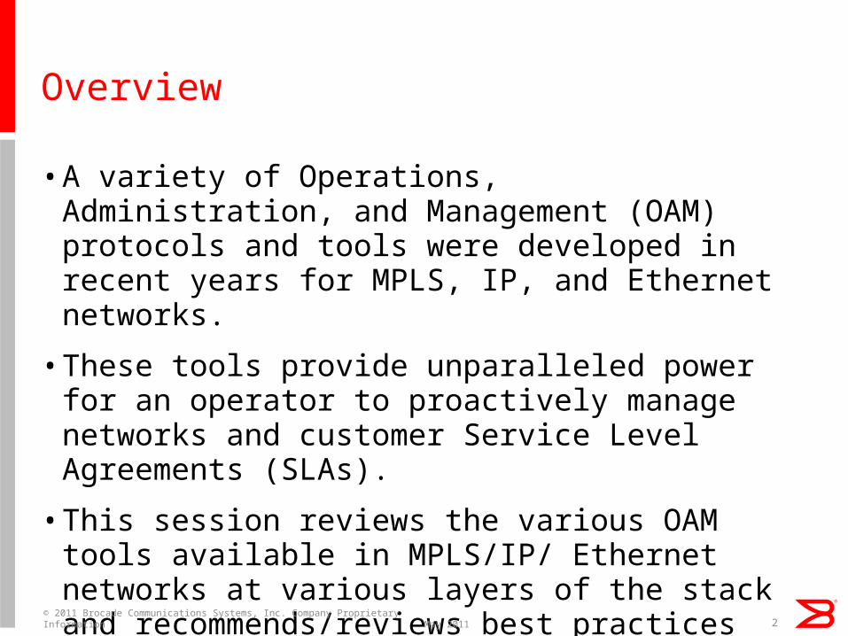
• A variety of Operations, Administration, and Management (OAM) protocols and tools were developed in recent years for MPLS, IP, and Ethernet networks.
• These tools provide unparalleled power for an operator to proactively manage networks and customer Service Level Agreements (SLAs).
• This session reviews the various OAM tools available in MPLS/IP/ Ethernet networks at various layers of the stack and recommends/reviews best practices for choosing the right OAM protocol to use in a network. May 2011
© 2011 Brocade Communications Systems, Inc. Company Proprietary Information 2
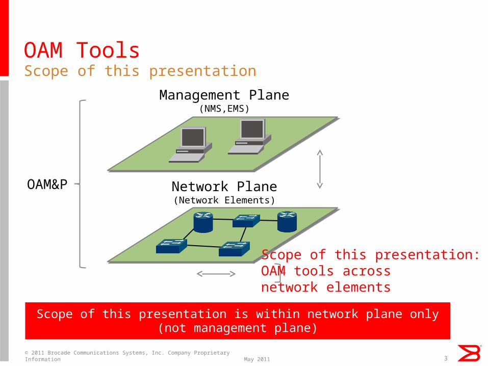
OAM ToolsScope of this presentation
May 2011© 2011 Brocade Communications Systems, Inc. Company Proprietary Information 3
Management Plane(NMS,EMS)
Network Plane(Network Elements)
Scope of this presentation:OAM tools acrossnetwork elements
OAM&P
Scope of this presentation is within network plane only(not management plane)
OAM Layering
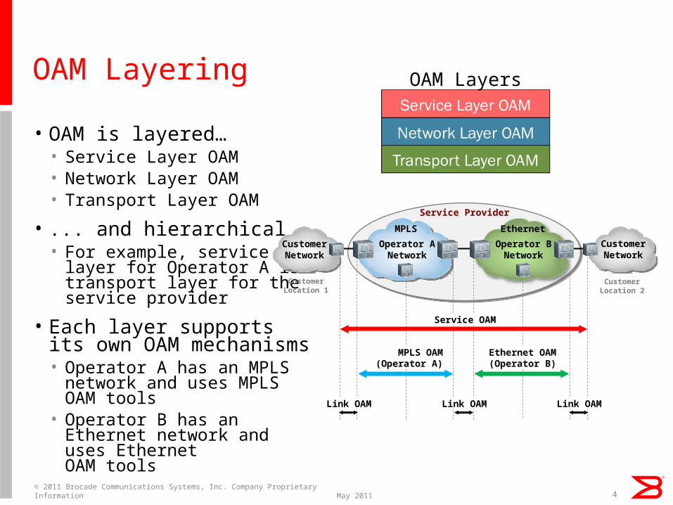
• OAM is layered…• Service Layer OAM• Network Layer OAM• Transport Layer OAM
• ... and hierarchical• For example, service
layer for Operator A is transport layer for theservice provider
• Each layer supports its own OAM mechanisms• Operator A has an MPLS
network and uses MPLS OAM tools
• Operator B has an Ethernet network and uses Ethernet OAM tools
May 2011© 2011 Brocade Communications Systems, Inc. Company Proprietary Information 4
Service Provider
Operator ANetwork
CustomerNetwork
CustomerNetwork
CustomerLocation 1
CustomerLocation 2
Operator BNetwork
Service OAM
MPLS OAM(Operator A)
Ethernet OAM(Operator B)
MPLS
Link OAM Link OAM Link OAM
Ethernet
OAM Layers
Layer 2
Trace
Port Loop
Detection
UDLDSingle-link
LACPKeep-alive
802.1ag CFM/
Y.1731 PM
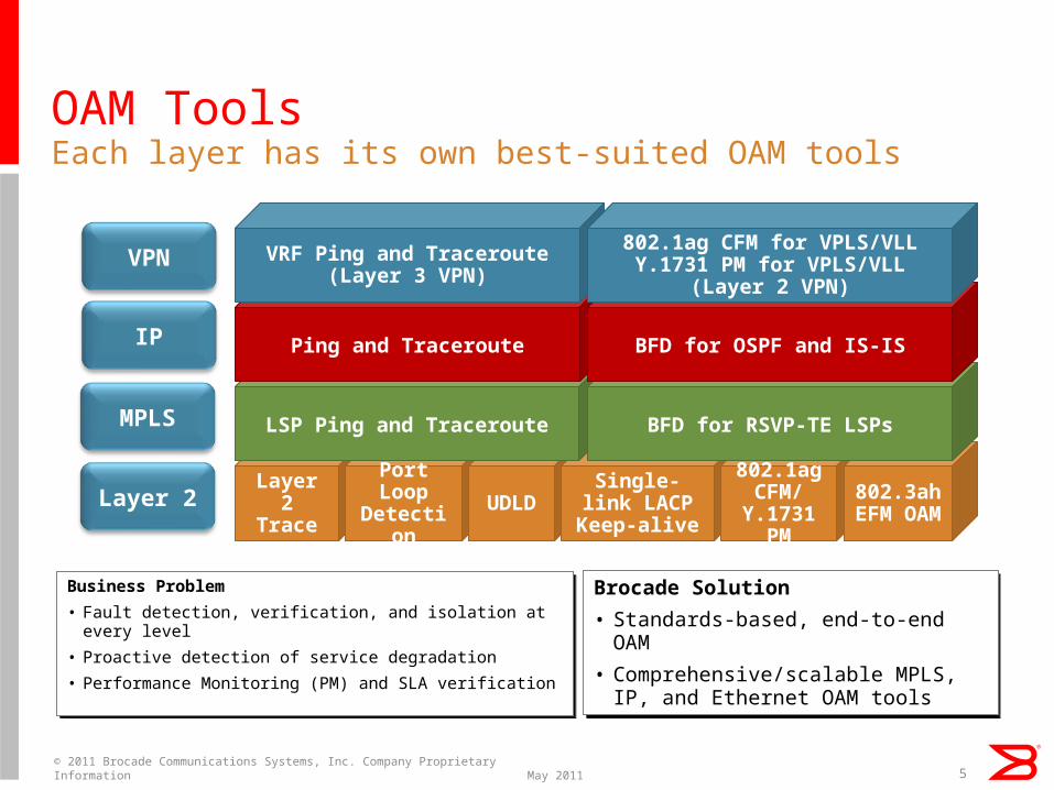
OAM Tools
Business Problem
• Fault detection, verification, and isolation at every level
• Proactive detection of service degradation
• Performance Monitoring (PM) and SLA verification
Business Problem
• Fault detection, verification, and isolation at every level
• Proactive detection of service degradation
• Performance Monitoring (PM) and SLA verification
Each layer has its own best-suited OAM tools
Brocade Solution
• Standards-based, end-to-end OAM
• Comprehensive/scalable MPLS, IP, and Ethernet OAM tools
Brocade Solution
• Standards-based, end-to-end OAM
• Comprehensive/scalable MPLS, IP, and Ethernet OAM tools
May 2011© 2011 Brocade Communications Systems, Inc. Company Proprietary Information 5
802.3ah
EFM OAM
LSP Ping and Traceroute BFD for RSVP-TE LSPs
Ping and Traceroute BFD for OSPF and IS-IS
VRF Ping and Traceroute(Layer 3 VPN)
802.1ag CFM for VPLS/VLLY.1731 PM for VPLS/VLL
(Layer 2 VPN)VPN
IP
Layer 2
MPLS
Layer 2 OAM+ Layer 2 VPN CFM/PM: 802.1ag CFM, Y.1731 PM
May 2011© 2011 Brocade Communications Systems, Inc. Company Proprietary Information 6
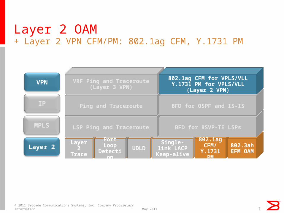
Layer 2 OAM+ Layer 2 VPN CFM/PM: 802.1ag CFM, Y.1731 PM
May 2011© 2011 Brocade Communications Systems, Inc. Company Proprietary Information 7
Layer 2
Trace
Port Loop
Detection
UDLDSingle-link
LACPKeep-alive
802.1ag CFM/
Y.1731 PM
802.3ah
EFM OAM
LSP Ping and Traceroute BFD for RSVP-TE LSPs
Ping and Traceroute BFD for OSPF and IS-IS
VRF Ping and Traceroute(Layer 3 VPN)
802.1ag CFM for VPLS/VLLY.1731 PM for VPLS/VLL
(Layer 2 VPN)VPN
IP
Layer 2
MPLS
IEEE 802.1ag CFM
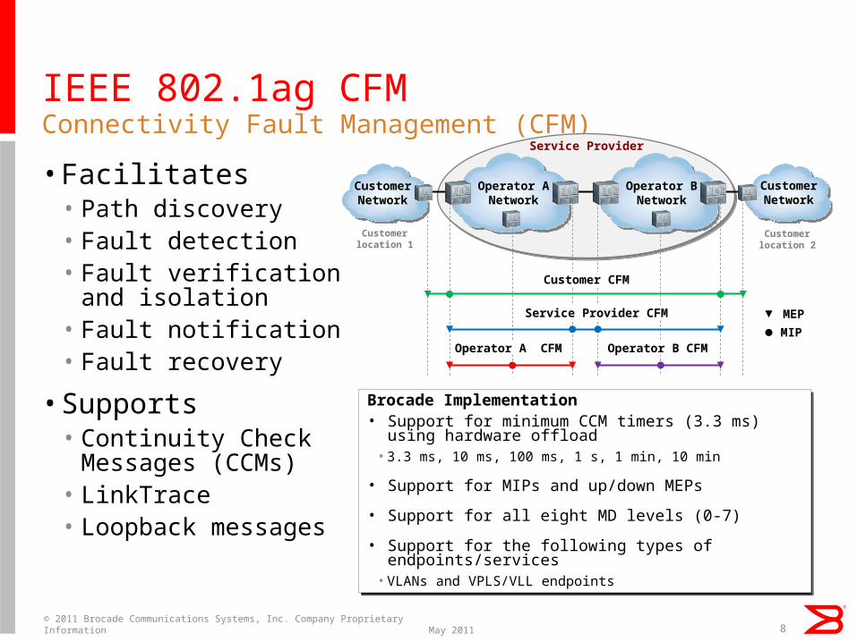
• Facilitates• Path discovery• Fault detection• Fault verification
and isolation• Fault notification• Fault recovery
• Supports• Continuity Check
Messages (CCMs)• LinkTrace• Loopback messages
Connectivity Fault Management (CFM)
Brocade Implementation• Support for minimum CCM timers (3.3 ms) using
hardware offload• 3.3 ms, 10 ms, 100 ms, 1 s, 1 min, 10 min
• Support for MIPs and up/down MEPs
• Support for all eight MD levels (0-7)
• Support for the following types of endpoints/services
• VLANs and VPLS/VLL endpoints
Brocade Implementation• Support for minimum CCM timers (3.3 ms) using
hardware offload• 3.3 ms, 10 ms, 100 ms, 1 s, 1 min, 10 min
• Support for MIPs and up/down MEPs
• Support for all eight MD levels (0-7)
• Support for the following types of endpoints/services
• VLANs and VPLS/VLL endpoints
8
Service Provider
Operator ANetwork
CustomerNetwork
CustomerNetwork
Customerlocation 1
Customerlocation 2
Operator BNetwork
MEP
MIP
Customer CFM
Service Provider CFM
Operator A CFM Operator B CFM
May 2011© 2011 Brocade Communications Systems, Inc. Company Proprietary Information
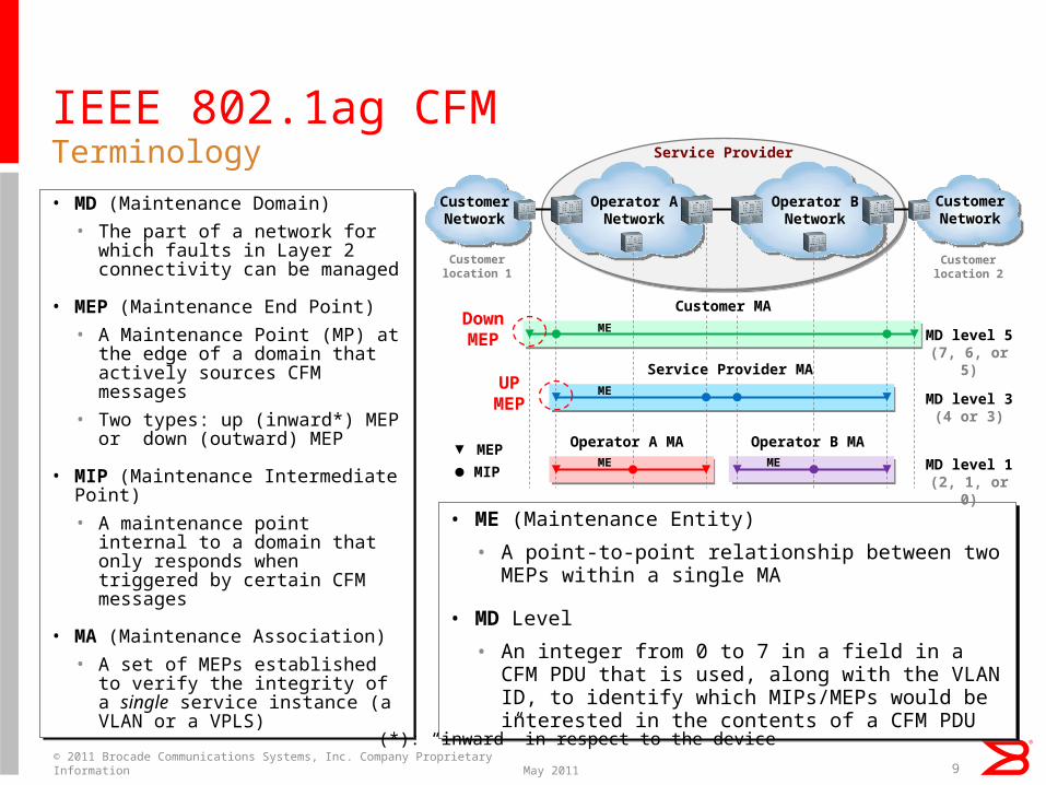
IEEE 802.1ag CFM
• MD (Maintenance Domain)
• The part of a network for which faults in Layer 2 connectivity can be managed
• MEP (Maintenance End Point)
• A Maintenance Point (MP) at the edge of a domain that actively sources CFM messages
• Two types: up (inward*) MEP or down (outward) MEP
• MIP (Maintenance Intermediate Point)
• A maintenance point internal to a domain that only responds when triggered by certain CFM messages
• MA (Maintenance Association)
• A set of MEPs established to verify the integrity of a single service instance (a VLAN or a VPLS)
Terminology
• ME (Maintenance Entity)
• A point-to-point relationship between two MEPs within a single MA
• MD Level
• An integer from 0 to 7 in a field in a CFM PDU that is used, along with the VLAN ID, to identify which MIPs/MEPs would be interested in the contents of a CFM PDU
• ME (Maintenance Entity)
• A point-to-point relationship between two MEPs within a single MA
• MD Level
• An integer from 0 to 7 in a field in a CFM PDU that is used, along with the VLAN ID, to identify which MIPs/MEPs would be interested in the contents of a CFM PDU
9
Service Provider
Operator ANetwork
CustomerNetwork
CustomerNetwork
Customerlocation 1
Customerlocation 2
Operator BNetwork
MEP
MIP
Customer MA
Service Provider MA
Operator A MA Operator B MA
MD level 5(7, 6, or 5)
MD level 3(4 or 3)
MD level 1(2, 1, or 0)
ME
ME
ME ME
DownMEP
UPMEP
(*): “inward” in respect to the device
May 2011© 2011 Brocade Communications Systems, Inc. Company Proprietary Information
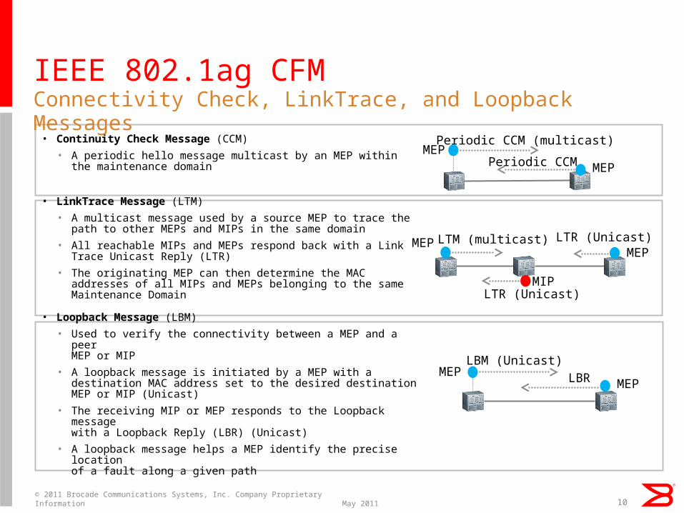
IEEE 802.1ag CFM
• Continuity Check Message (CCM)
• A periodic hello message multicast by an MEP within the maintenance domain
• LinkTrace Message (LTM)
• A multicast message used by a source MEP to trace the path to other MEPs and MIPs in the same domain
• All reachable MIPs and MEPs respond back with a Link Trace Unicast Reply (LTR)
• The originating MEP can then determine the MAC addresses of all MIPs and MEPs belonging to the same Maintenance Domain
• Loopback Message (LBM)
• Used to verify the connectivity between a MEP and a peer MEP or MIP
• A loopback message is initiated by a MEP with a destination MAC address set to the desired destination MEP or MIP (Unicast)
• The receiving MIP or MEP responds to the Loopback message with a Loopback Reply (LBR) (Unicast)
• A loopback message helps a MEP identify the precise location of a fault along a given path
Connectivity Check, LinkTrace, and Loopback Messages
10
Periodic CCM (multicast)
Periodic CCMMEP
MEP
LTM (multicast) LTR (Unicast)MEPMEP
MIP
LBM (Unicast)LBRMEP
MEP
LTR (Unicast)
May 2011© 2011 Brocade Communications Systems, Inc. Company Proprietary Information
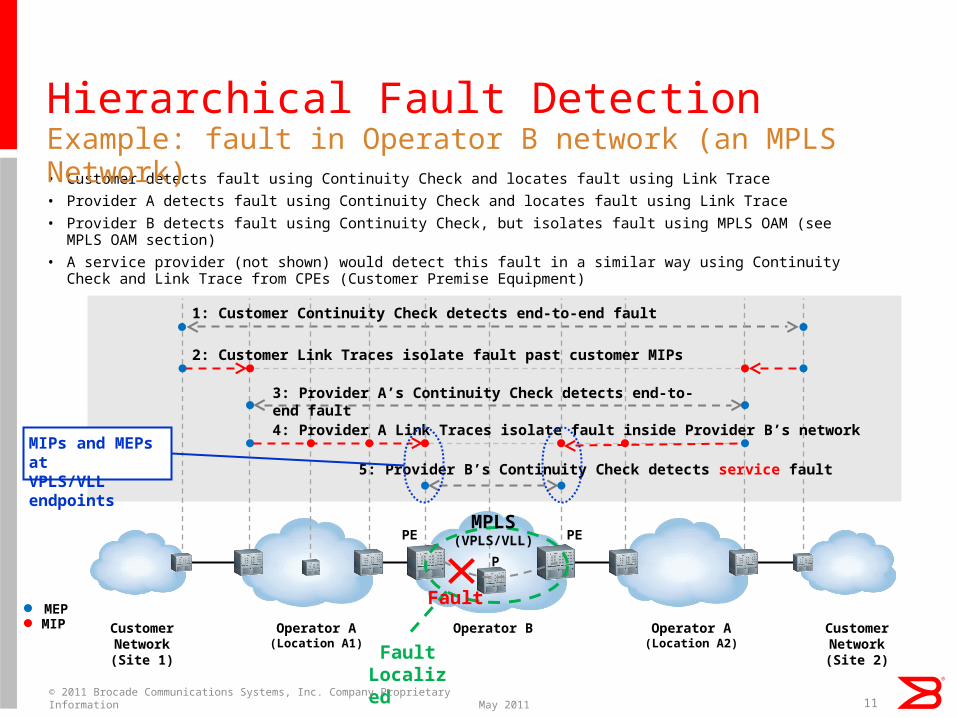
Hierarchical Fault Detection
• Customer detects fault using Continuity Check and locates fault using Link Trace
• Provider A detects fault using Continuity Check and locates fault using Link Trace
• Provider B detects fault using Continuity Check, but isolates fault using MPLS OAM (see MPLS OAM section)
• A service provider (not shown) would detect this fault in a similar way using Continuity Check and Link Trace from CPEs (Customer Premise Equipment)
Example: fault in Operator B network (an MPLS Network)
P
MEPMIP
3: Provider A’s Continuity Check detects end-to-end fault4: Provider A Link Traces isolate fault inside Provider B’s network
1: Customer Continuity Check detects end-to-end fault
2: Customer Link Traces isolate fault past customer MIPs
5: Provider B’s Continuity Check detects service fault
Operator BOperator A(Location A1)
CustomerNetwork(Site 1)
Operator A(Location A2)
CustomerNetwork(Site 2)Fault
Localized
PEPEMPLS
(VPLS/VLL)
MIPs and MEPs atVPLS/VLL endpoints
Fault
11May 2011© 2011 Brocade Communications Systems, Inc. Company Proprietary Information
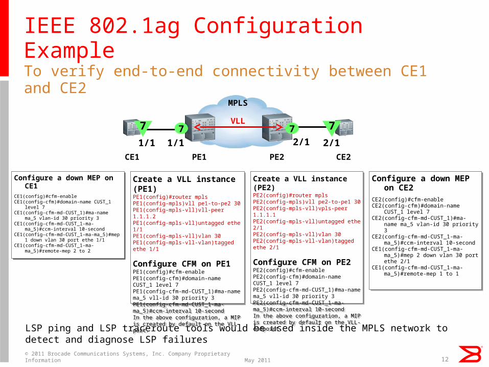
IEEE 802.1ag Configuration Example
Configure a down MEP on CE1
CE1(config)#cfm-enableCE1(config-cfm)#domain-name CUST_1
level 7CE1(config-cfm-md-CUST_1)#ma-name
ma_5 vlan-id 30 priority 3CE1(config-cfm-md-CUST_1-ma-ma_5)#ccm-
interval 10-secondCE1(config-cfm-md-CUST_1-ma-ma_5)#mep
1 down vlan 30 port ethe 1/1CE1(config-cfm-md-CUST_1-ma-
ma_5)#remote-mep 2 to 2
To verify end-to-end connectivity between CE1 and CE2
12
CE1 CE2
7 77 7
1/1 1/1 2/1 2/1PE1 PE2
MPLS
VLL
Configure a down MEP on CE2
CE2(config)#cfm-enableCE2(config-cfm)#domain-name
CUST_1 level 7CE2(config-cfm-md-CUST_1)#ma-
name ma_5 vlan-id 30 priority 3CE2(config-cfm-md-CUST_1-ma-
ma_5)#ccm-interval 10-secondCE1(config-cfm-md-CUST_1-ma-
ma_5)#mep 2 down vlan 30 port ethe 2/1
CE1(config-cfm-md-CUST_1-ma-ma_5)#remote-mep 1 to 1
LSP ping and LSP traceroute tools would be used inside the MPLS network to detect and diagnose LSP failures
Create a VLL instance (PE1)PE1(config)#router mplsPE1(config-mpls)vll pe1-to-pe2 30PE1(config-mpls-vll)vll-peer 1.1.1.2PE1(config-mpls-vll)untagged ethe 1/1PE1(config-mpls-vll)vlan 30PE1(config-mpls-vll-vlan)tagged ethe 1/1
Configure CFM on PE1PE1(config)#cfm-enablePE1(config-cfm)#domain-name CUST_1 level 7PE1(config-cfm-md-CUST_1)#ma-name ma_5 vll-id 30 priority 3PE1(config-cfm-md-CUST_1-ma-ma_5)#ccm-interval 10-secondIn the above configuration, a MIP is created by default on the VLL port.
Create a VLL instance (PE2)PE2(config)#router mplsPE2(config-mpls)vll pe2-to-pe1 30PE2(config-mpls-vll)vpls-peer 1.1.1.1PE2(config-mpls-vll)untagged ethe 2/1PE2(config-mpls-vll)vlan 30PE2(config-mpls-vll-vlan)tagged ethe 2/1
Configure CFM on PE2PE2(config)#cfm-enablePE2(config-cfm)#domain-name CUST_1 level 7PE2(config-cfm-md-CUST_1)#ma-name ma_5 vll-id 30 priority 3PE2(config-cfm-md-CUST_1-ma-ma_5)#ccm-interval 10-secondIn the above configuration, a MIP is created by default on the VLL-endpoint.
May 2011© 2011 Brocade Communications Systems, Inc. Company Proprietary Information
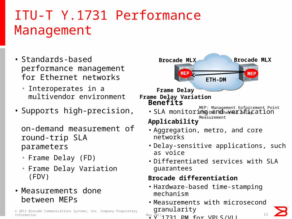
ITU-T Y.1731 Performance Management
• Standards-based performance management for Ethernet networks• Interoperates in a
multivendor environment
• Supports high-precision, on-demand measurement of round-trip SLA parameters• Frame Delay (FD)
• Frame Delay Variation (FDV)
• Measurements done between MEPs
13
MEP
Frame DelayFrame Delay Variation
ETH-DM
Brocade MLX Brocade MLX
MEP: Management Enforcement PointETH-DM: Ethernet Delay Measurement
Benefits• SLA monitoring and verification
Applicability• Aggregation, metro, and core networks• Delay-sensitive applications, such as
voice• Differentiated services with SLA
guarantees
Brocade differentiation• Hardware-based time-stamping
mechanism• Measurements with microsecond
granularity• Y.1731 PM for VPLS/VLL
MEP
May 2011© 2011 Brocade Communications Systems, Inc. Company Proprietary Information
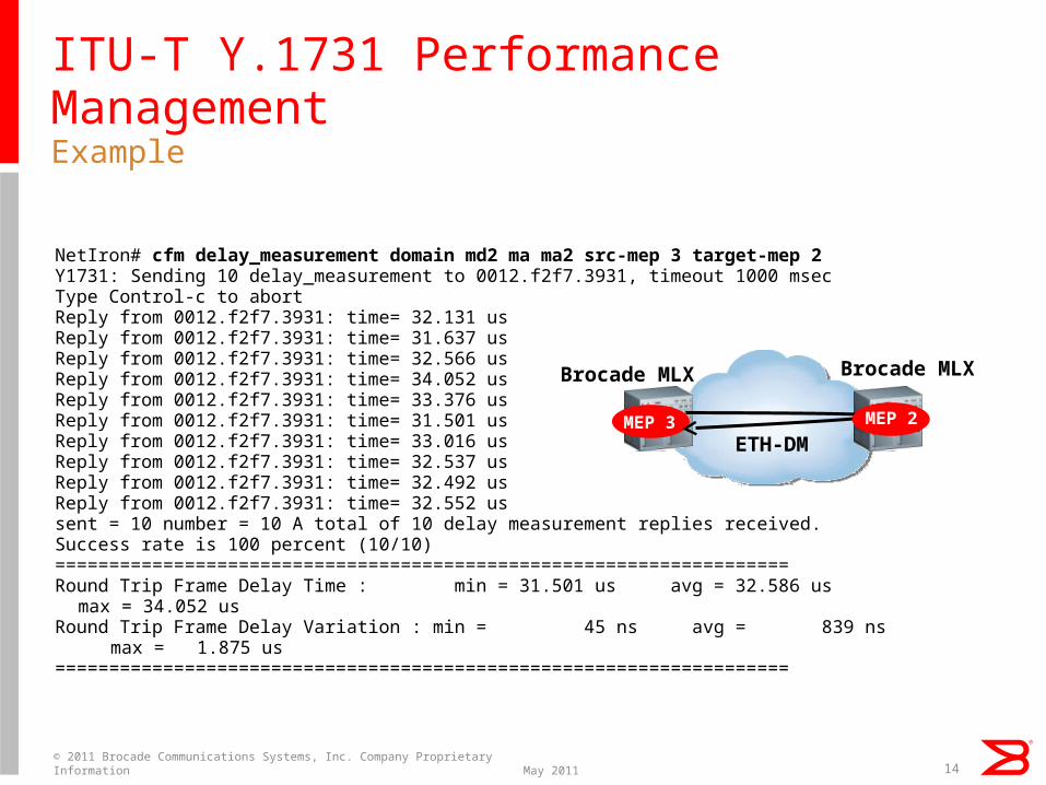
ITU-T Y.1731 Performance ManagementExample
14
NetIron# cfm delay_measurement domain md2 ma ma2 src-mep 3 target-mep 2Y1731: Sending 10 delay_measurement to 0012.f2f7.3931, timeout 1000 msecType Control-c to abortReply from 0012.f2f7.3931: time= 32.131 usReply from 0012.f2f7.3931: time= 31.637 usReply from 0012.f2f7.3931: time= 32.566 usReply from 0012.f2f7.3931: time= 34.052 usReply from 0012.f2f7.3931: time= 33.376 usReply from 0012.f2f7.3931: time= 31.501 usReply from 0012.f2f7.3931: time= 33.016 usReply from 0012.f2f7.3931: time= 32.537 usReply from 0012.f2f7.3931: time= 32.492 usReply from 0012.f2f7.3931: time= 32.552 ussent = 10 number = 10 A total of 10 delay measurement replies received.Success rate is 100 percent (10/10)=======================================================
=============Round Trip Frame Delay Time : min = 31.501 us avg = 32.586 us max = 34.052 usRound Trip Frame Delay Variation : min = 45 ns avg = 839 ns max = 1.875
us=======================================================
=============
MEP 3ETH-DM
Brocade MLX Brocade MLX
MEP 2
May 2011© 2011 Brocade Communications Systems, Inc. Company Proprietary Information
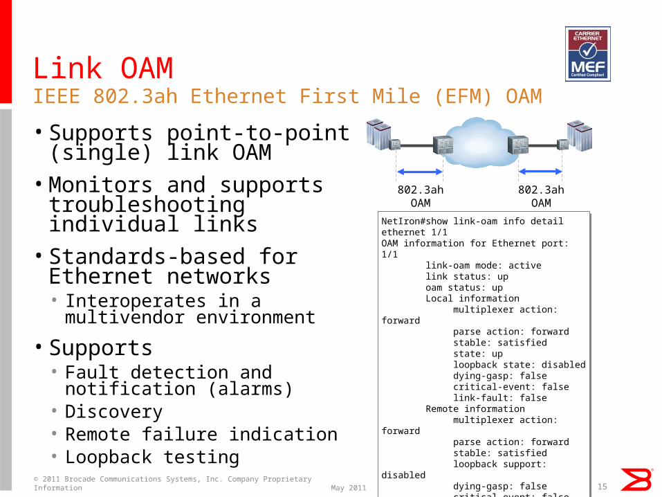
Link OAM
• Supports point-to-point (single) link OAM• Monitors and supports
troubleshooting individual links• Standards-based for
Ethernet networks• Interoperates in a multivendor
environment
• Supports• Fault detection and notification
(alarms)• Discovery• Remote failure indication• Loopback testing
IEEE 802.3ah Ethernet First Mile (EFM) OAM
802.3ahOAM
802.3ahOAM
NetIron#show link-oam info detail ethernet 1/1OAM information for Ethernet port: 1/1 link-oam mode: active link status: up oam status: up Local information multiplexer action: forward parse action: forward stable: satisfied state: up loopback state: disabled dying-gasp: false critical-event: false link-fault: false Remote information multiplexer action: forward parse action: forward stable: satisfied loopback support: disabled dying-gasp: false critical-event: false link-fault: false
NetIron#show link-oam info detail ethernet 1/1OAM information for Ethernet port: 1/1 link-oam mode: active link status: up oam status: up Local information multiplexer action: forward parse action: forward stable: satisfied state: up loopback state: disabled dying-gasp: false critical-event: false link-fault: false Remote information multiplexer action: forward parse action: forward stable: satisfied loopback support: disabled dying-gasp: false critical-event: false link-fault: false
15May 2011© 2011 Brocade Communications Systems, Inc. Company Proprietary Information
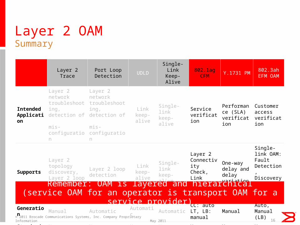
Layer 2 OAMSummary
16
Layer 2Trace
Port Loop Detection
UDLDSingle-LinkKeep-Alive
802.1ag CFM
Y.1731 PM802.3ahEFM OAM
IntendedApplication
Layer 2 networktroubleshooting, detection of
mis-configuration
Layer 2 networktroubleshooting, detection of
mis-configuration
Linkkeep-alive
Single-link keep-alive
Serviceverification
Performance (SLA) verification
Customer accessverification
Supports
Layer 2 topology discovery,Layer 2 loop detection
Layer 2 loop detection
Linkkeep-alive
Single-link keep-alive
Layer 2Connectivity Check,Link Trace,Loopback
One-way delay and delay variation
Single-link OAM: Fault Detection, Discovery, Loop-back, and so on
Generation
Manual Automatic Automatic AutomaticCC: autoLT, LB: manual
ManualAuto,Manual (LB)
Standard No No No Yes Yes Yes YesRemember: OAM is layered and hierarchical(service OAM for an operator is transport OAM for a service
provider)
May 2011© 2011 Brocade Communications Systems, Inc. Company Proprietary Information

MPLS OAM
17May 2011© 2011 Brocade Communications Systems, Inc. Company Proprietary Information

MPLS OAM
18
Layer 2
Trace
Port Loop
Detection
UDLDSingle-link
LACPKeep-alive
802.1ag CFM/
Y.1731 PM
802.3ah
EFM OAM
LSP Ping and Traceroute BFD for RSVP-TE LSPs
Ping and Traceroute BFD for OSPF and IS-IS
VRF Ping and Traceroute(Layer 3 VPN)
802.1ag CFM for VPLS/VLLY.1731 PM for VPLS/VLL
(Layer 2 VPN)VPN
IP
Layer 2
MPLS
May 2011© 2011 Brocade Communications Systems, Inc. Company Proprietary Information
LSP Ping and LSP Traceroute
• LSP Ping and LSP Traceroute provide OAM functionality for MPLS networks based on RFC 4379.
• LSP Ping and LSP Traceroute tools provide a mechanism to detect MPLS data plane failure.• MPLS echo requests follow the same data path that
normal MPLS packets would traverse.
• LSP Ping is used to detect data plane failure and to check the consistency between the data plane and the control plane.
• LSP Traceroute is used to isolate the data plane failure to a particular router and to provide LSP path tracing.
MPLS OAM tools
19May 2011© 2011 Brocade Communications Systems, Inc. Company Proprietary Information
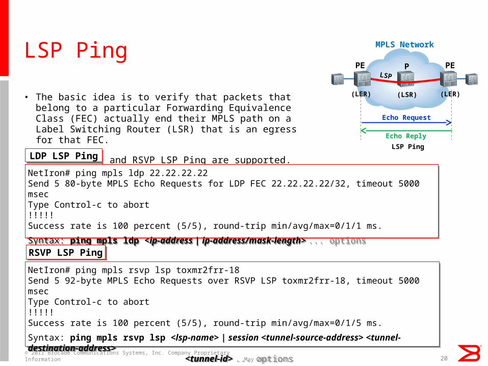
LSP Ping
• The basic idea is to verify that packets that belong to a particular Forwarding Equivalence Class (FEC) actually end their MPLS path on a Label Switching Router (LSR) that is an egress for that FEC.
• LDP LSP Ping and RSVP LSP Ping are supported.
20
NetIron# ping mpls ldp 22.22.22.22Send 5 80-byte MPLS Echo Requests for LDP FEC 22.22.22.22/32, timeout 5000 msecType Control-c to abort!!!!!Success rate is 100 percent (5/5), round-trip min/avg/max=0/1/1 ms.
Syntax: ping mpls ldp <ip-address | ip-address/mask-length> ... options
NetIron# ping mpls ldp 22.22.22.22Send 5 80-byte MPLS Echo Requests for LDP FEC 22.22.22.22/32, timeout 5000 msecType Control-c to abort!!!!!Success rate is 100 percent (5/5), round-trip min/avg/max=0/1/1 ms.
Syntax: ping mpls ldp <ip-address | ip-address/mask-length> ... options
LDP LSP PingLDP LSP Ping
NetIron# ping mpls rsvp lsp toxmr2frr-18Send 5 92-byte MPLS Echo Requests over RSVP LSP toxmr2frr-18, timeout 5000 msecType Control-c to abort!!!!!Success rate is 100 percent (5/5), round-trip min/avg/max=0/1/5 ms.
Syntax: ping mpls rsvp lsp <lsp-name> | session <tunnel-source-address> <tunnel-destination-address> <tunnel-id> ... options
RSVP LSP Ping
RSVP LSP Ping
MPLS Network
PE P
(LER) (LSR)
PE
(LER)
LSP
LSP Ping
Echo Request
Echo Reply
May 2011© 2011 Brocade Communications Systems, Inc. Company Proprietary Information

LSP Traceroute
• With LSP traceroute, an echo request packet is sent to the control plane of each transit LSR, which confirms that it is a transit LSR for this path.
• Transit LSRs return echo replies.
• LDP LSP Ping and RSVP LSP Ping are supported.
21
NetIron# traceroute mpls ldp 22.22.22.22Trace LDP LSP to 22.22.22.22/32, timeout 5000 msec, TTL 1 to 30Type Control-c to abort1 10ms 22.22.22.22 return code 3(Egress)
Syntax: traceroute mpls ldp < ip-address | ip-address/mask-length> ... options
NetIron# traceroute mpls ldp 22.22.22.22Trace LDP LSP to 22.22.22.22/32, timeout 5000 msec, TTL 1 to 30Type Control-c to abort1 10ms 22.22.22.22 return code 3(Egress)
Syntax: traceroute mpls ldp < ip-address | ip-address/mask-length> ... options
LDP LSP TracerouteLDP LSP
Traceroute
NetIron # traceroute mpls rsvp lsp toxmr2frr-18Trace RSVP LSP toxmr2frr-18, timeout 5000 msec, TTL 1 to 30Type Control-c to abort1 1ms 22.22.22.22 return code 3(Egress)
Syntax: traceroute mpls rsvp lsp <lsp-name> | session <tunnel-source-address> <tunneldestination-address> <tunnel-id>... options
NetIron # traceroute mpls rsvp lsp toxmr2frr-18Trace RSVP LSP toxmr2frr-18, timeout 5000 msec, TTL 1 to 30Type Control-c to abort1 1ms 22.22.22.22 return code 3(Egress)
Syntax: traceroute mpls rsvp lsp <lsp-name> | session <tunnel-source-address> <tunneldestination-address> <tunnel-id>... options
RSVP LSP TracerouteRSVP LSP
Traceroute
MPLS Network
PE P
(LER) (LSR)
PE
(LER)
LSP
LSP Traceroute
Echo Request
Echo Replies
May 2011© 2011 Brocade Communications Systems, Inc. Company Proprietary Information
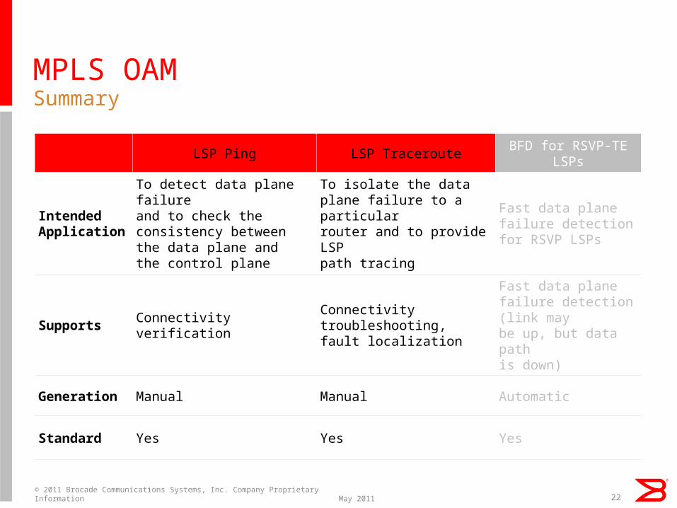
MPLS OAMSummary
LSP Ping LSP TracerouteBFD for RSVP-TE
LSPs
IntendedApplication
To detect data plane failure and to check the consistency between the data plane and the control plane
To isolate the data plane failure to a particular router and to provide LSP
path tracing
Fast data plane failure detection for RSVP LSPs
Supports Connectivity verificationConnectivity troubleshooting,fault localization
Fast data plane failure detection (link may be up, but data path
is down)
Generation Manual Manual Automatic
Standard Yes Yes Yes
22May 2011© 2011 Brocade Communications Systems, Inc. Company Proprietary Information
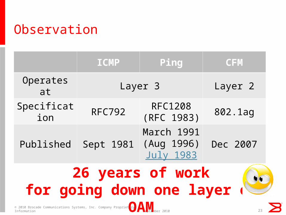
Observation
September 2010© 2010 Brocade Communications Systems, Inc. Company Proprietary Information 23
ICMP Ping CFM
Operates at Layer 3 Layer 2
Specification
RFC792RFC1208
(RFC 1983)802.1ag
Published Sept 1981March 1991(Aug 1996)July 1983
Dec 2007
26 years of workfor going down one layer of
OAM

Thank You
24© 2011 Brocade Communications Systems, Inc. Company Proprietary Information