Embed Size (px)
Citation preview

Practical Steel Connection Software Design Using AISC 2010 Standard
Including:Practical Advice for Reviewing Software
Generated Connection Designs
Steve Ashton, P.E., SECB

2
Limit States that Changed

Bolt Limit States
3

Bolt Materials
Group A: (Includes A325 and F1852)Fu = 120 ksi *
Group B: (Includes A490 and F2280)Fu = 150 ksi
(* ‐ up to 1” diameter)
4

Allowable Shear Strength
1989 2005 2010A325N 21 ksi 24 ksi 27 ksiA325X 30 ksi 30 ksi 34 ksiA490N 28 ksi 30 ksi 34 ksiA490X 40 ksi 37.5 ksi 42 ksi
5

Table J3.2 ‐ 2005
6

Table J3.2 ‐ 2010
7

Bolt Limit States
8

Slip Critical Joints ‐ 2005 SpecificationRn = μDuhscTbNs (J3‐4)
Prevention of Slip is a Serviceability Limit StateLRFD: = 1.00ASD: = 1.50
Prevention of Slip at Required Strength LevelLRFD: = 0.85ASD: = 1.76
9

Rn = μDuhscTbNs (2005 ‐ J3‐4)
= 0.35 (Class A) = 0.50 (Class B)
Rn = μDuhfTbNs (2010 ‐ J3‐4)
= 0.30 (Class A) = 0.50 (Class B)
Slip Critical Joints
10

Rn = μDuhscTbNs (2005 ‐ J3‐4)
hsc = 1.00 (STD)hsc = 0.85 (OVS or SSL)hsc = 0.70 (LSL)
Rn = μDuhfTbNs (2010 ‐ J3‐4)
= 1.00 (STD) = 0.85 (OVS or SSL) = 0.70 (LSL)
Slip Critical Joints
11

Slip Critical Joints ‐ 2010 Specification
Rn = μDuhfTbNs (J3‐4)
hf = 1.00 (0 or 1 Filler)hf = 0.85 (2 or more Fillers)
12

Limit States
13

New Section J4.5
14

Other 14th Ed. Changes• Prying Action• Single Plate Shear Connections (Shear Tabs)• Fillers• New Tables
15

Other 14th Ed. Changes
• Prying Action• Single Plate Shear Connections (Shear Tabs)• Fillers• New Tables
16

17
Prying Action (ASD)
With prying action:
T = required strength per boltp = tributary length per bolt line ≤ 2b = 1‐ d’ / pd’ = width of hole along length of fitting
)'1('4
min
upF
Tbt

Prying Action Nomenclature

19
Prying ActionDouble Angle Connection

Expanded Bolt Spacing
20

21
Wide Gage

22
Narrow Gage

23
Narrow Gage and Expanded Bolt Spacing
Other 14th Ed. Changes
• Prying Action• Single Plate Connections (Shear Tabs)• Fillers• New Tables
24
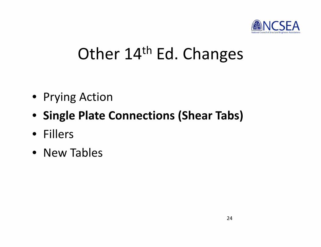
Conventional Configuration
25

Conventional Configuration
26

Single‐Plate Connection
Conventional Configuration
13th Edition Manualtp or tw ≤ d/2 + 1/16”
14th Edition ManualNo requirement if n ≤ 5 and SSLT
27

Single‐Plate Connection
Conventional Configuration
13th Edition ManualEccentricity can be ignored if:
n ≤ 9 and STD or n ≤ 12 and SSLT
14th Edition ManualEccentricity always considered per Table 10‐9
28

Other 14th Ed. Changes• Prying Action• Single Plate Shear Connections (Shear Tabs)• Fillers• New Tables
29

Fillers
30

Fillers: J5 ‐ 2005
31
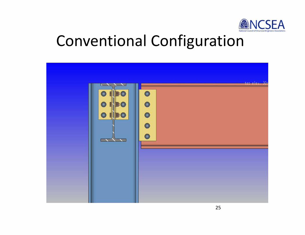
Fillers: J5.2 ‐ 2010
32
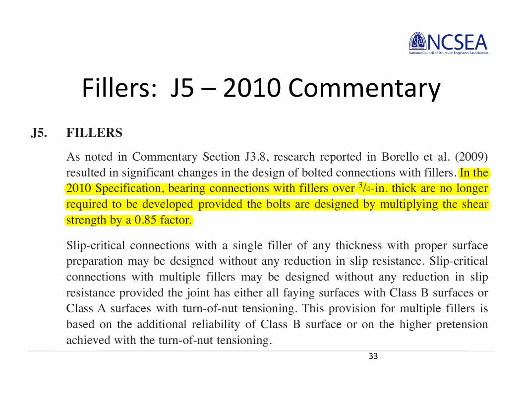
Fillers: J5 – 2010 Commentary
33

Other 14th Ed. Changes• Prying Action• Single Plate Shear Connections (Shear Tabs)• Fillers• New Tables
34

14th Edition Manual
New Tools• Table 8‐12. Approx. Number of Passes for Welds• Table 10‐13. Min. Inside Radius for Cold‐Bending• Table 10‐14. Clearances for Skewed Connections• Table 10‐15. Seated Connections to HSS
35
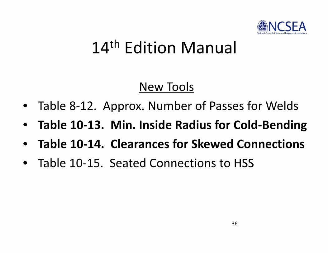
14th Edition Manual
New Tools• Table 8‐12. Approx. Number of Passes for Welds• Table 10‐13. Min. Inside Radius for Cold‐Bending• Table 10‐14. Clearances for Skewed Connections• Table 10‐15. Seated Connections to HSS
36

37
Tables 10‐13 and 10‐14

14th Edition Manual
New Tools• Table 8‐12. Approx. Number of Passes for Welds• Table 10‐13. Min. Inside Radius for Cold‐Bending• Table 10‐14. Clearances for Skewed Connections• Table 10‐15. Seated Connections to HSS
38

39
Table 10‐15

Practical Steel Connection Software Design Using AISC 2010 Standard
Practical Advice for Reviewing Software Generated Connection
Designs

Software Generated Calculations

Reviewing Software Generated Connection Designs
• Look at Every Connection• Know the Required Strengths• Determine the Load Path• Estimate the Capacity
– See “Evaluating a Connection” Handout– Quick Hand Calculations (Numbers to Memorize)– Printed Calculations
• Evaluate Constructability!
42

Reviewing Software Generated Connection Designs
• Look at Every Connection• Know the Required Strengths• Determine the Load Path• Estimate the Capacity
– See “Evaluating a Connection” Handout– Quick Hand Calculations (Numbers to Memorize)– Printed Calculations
• Evaluate Constructability!
43

Reviewing Software Generated Connection Designs
• Look at Every Connection• Know the Required Strengths• Determine the Load Path• Estimate the Capacity
– See “Evaluating a Connection” Handout– Quick Hand Calculations (Numbers to Memorize)– Printed Calculations
• Evaluate Constructability!
44

45
Required StrengthsAISC COSP Section 3.1.2

46
Transfer Forces

47
Transfer Forces

48
Transfer Forces

49
Transfer Forces

50
Transfer Forces

Reviewing Software Generated Connection Designs
• Look at Every Connection• Know the Required Strengths• Determine the Load Path• Estimate the Capacity
– See “Evaluating a Connection” Handout– Quick Hand Calculations (Numbers to Memorize)– Printed Calculations
• Evaluate Constructability!
51

52
Load Path ‐ Uniform Force Method
53
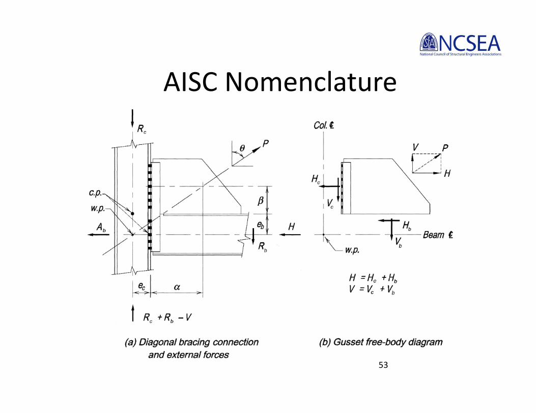
AISC Nomenclature

54
Column Forces
Beam forces
Where
and
PreP
rV c
c cH
PreP
rH b
b bV
22bc eer
Uniform Force Method(Equations from Manual)
cb ee tantan

55
Uniform Force Method (Traditional)
56
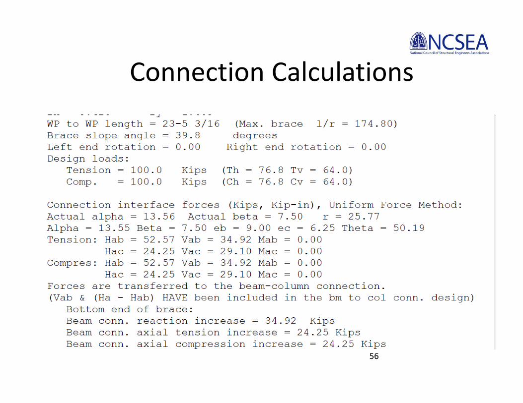
Connection Calculations

57
Uniform Force Method (Compact Gusset)

58
Connection Calculations

59
Workpoint Relocation (Special Case 1)

60
Workpoint Relocation (Special Case 1)

61
Workpoint Relocation (Special Case 1)

Reviewing Software Generated Connection Designs
• Look at Every Connection• Know the Required Strengths• Determine the Load Path• Estimate the Capacity
– See “Evaluating a Connection” Handout– Quick Hand Calculations (Numbers to Memorize)– Printed Calculations
• Evaluate Constructability!
62

63
Calculating Capacity

64
Calculating Capacity
65
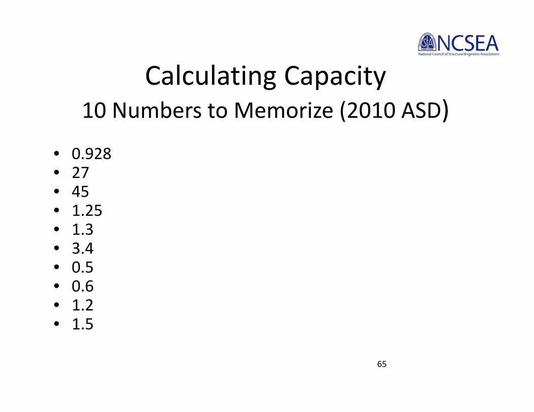
Calculating Capacity10 Numbers to Memorize (2010 ASD)
• 0.928• 27• 45• 1.25• 1.3• 3.4• 0.5• 0.6• 1.2• 1.5

Reviewing Software Generated Connection Designs
• Look at Every Connection• Know the Required Strengths• Determine the Load Path• Estimate the Capacity
– See “Evaluating a Connection” Handout– Quick Hand Calculations (Numbers to Memorize)– Printed Calculations
• Evaluate Constructability!
66

Constructability

Constructability

Constructability

Constructability

Constructability

Constructability

Constructability

Connection Costs

Connection Costs

Connection Costs
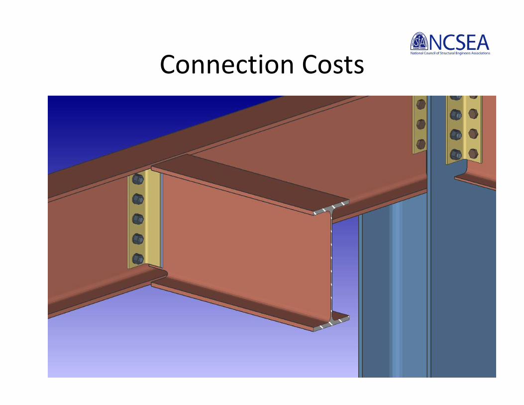
Connection Costs

SummaryReviewing Software Generated Connection
Designs• Look at Every Connection• Know the Required Strengths• Determine the Load Path• Estimate the Capacity
– See “Evaluating a Connection” Handout– Quick Hand Calculations (Numbers to Memorize)– Printed Calculations
• Evaluate Constructability!
78