Embed Size (px)
Citation preview

BETTER THAN THE OEM
$29.95 USD
TROUBLESHOOTING GUIDEPRACTICAL OUTBOARD IGNITION
6th Edition

11111111TECH SUPPORT 1.866.423.4832 CUSTOMER SERVICE 1.800.467.3371 www.cdielectronics.comTECH SUPPORT 1.866.423.4832 CUSTOMER SERVICE 1.800.467.3371 www.cdielectronics.comTECH SUPPORT 1.866.423.4832 CUSTOMER SERVICE 1.800.467.3371 www.cdielectronics.comTECH SUPPORT 1.866.423.4832 CUSTOMER SERVICE 1.800.467.3371 www.cdielectronics.com
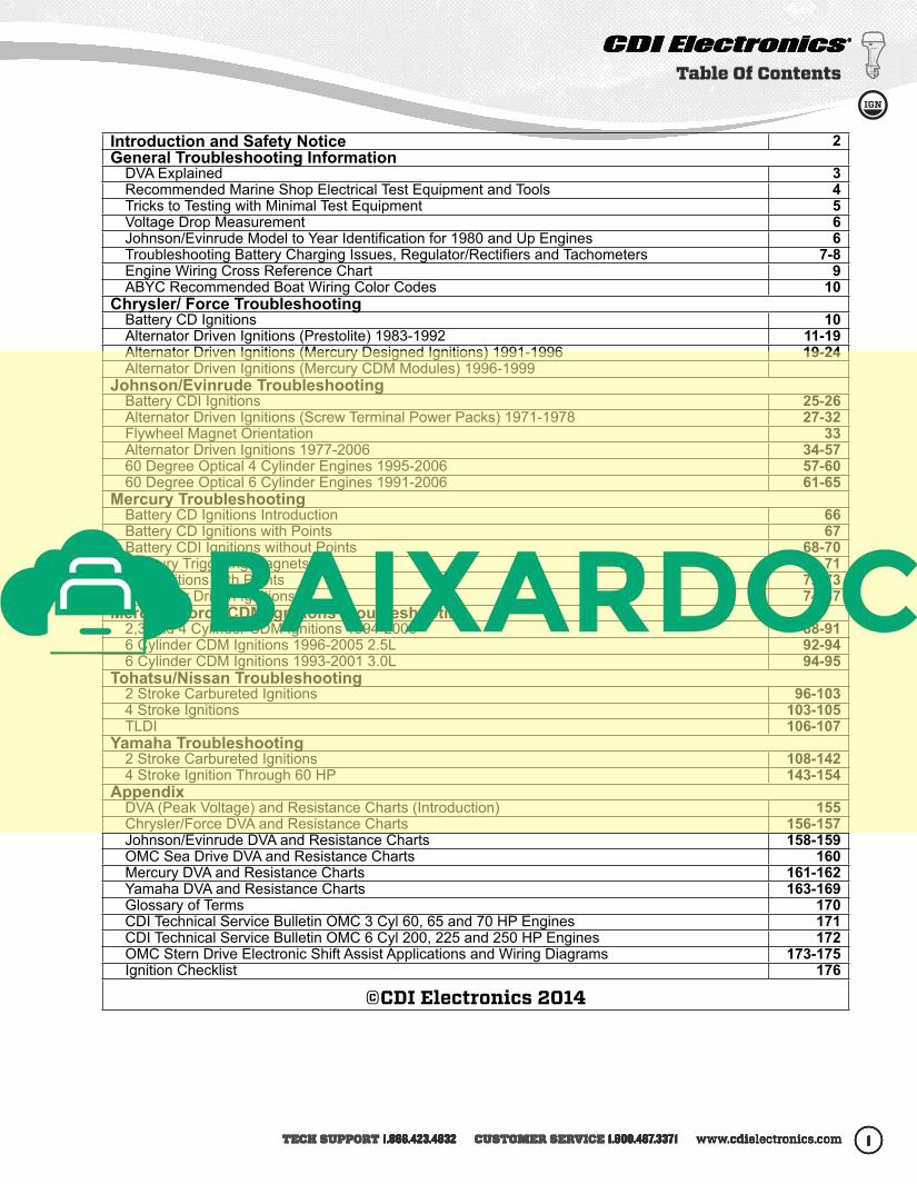
Introduction and Safety Notice 2General Troubleshooting Information
DVA Explained 3Recommended Marine Shop Electrical Test Equipment and Tools 4Tricks to Testing with Minimal Test Equipment 5Voltage Drop Measurement 6Johnson/Evinrude Model to Year Identification for 1980 and Up Engines 6Troubleshooting Battery Charging Issues, Regulator/Rectifiers and Tachometers 7-8Engine Wiring Cross Reference Chart 9ABYC Recommended Boat Wiring Color Codes 10
Chrysler/ Force TroubleshootingBattery CD Ignitions 10Alternator Driven Ignitions (Prestolite) 1983-1992 11-19Alternator Driven Ignitions (Mercury Designed Ignitions) 1991-1996 19-24Alternator Driven Ignitions (Mercury CDM Modules) 1996-1999
Johnson/Evinrude TroubleshootingBattery CDI Ignitions 25-26Alternator Driven Ignitions (Screw Terminal Power Packs) 1971-1978 27-32Flywheel Magnet Orientation 33Alternator Driven Ignitions 1977-2006 34-5760 Degree Optical 4 Cylinder Engines 1995-2006 57-6060 Degree Optical 6 Cylinder Engines 1991-2006 61-65
Mercury TroubleshootingBattery CD Ignitions Introduction 66Battery CD Ignitions with Points 67Battery CDI Ignitions without Points 68-70Mercury Triggering Magnets 71ADI Ignitions with Points 72-73Alternator Driven Ignitions 74-87
Mercury/Force CDM Ignitions Troubleshooting2,3 and 4 Cylinder CDM Ignitions 1994-2006 88-916 Cylinder CDM Ignitions 1996-2005 2.5L 92-946 Cylinder CDM Ignitions 1993-2001 3.0L 94-95
Tohatsu/Nissan Troubleshooting2 Stroke Carbureted Ignitions 96-1034 Stroke Ignitions 103-105TLDI 106-107
Yamaha Troubleshooting2 Stroke Carbureted Ignitions 108-1424 Stroke Ignition Through 60 HP 143-154
AppendixDVA (Peak Voltage) and Resistance Charts (Introduction) 155Chrysler/Force DVA and Resistance Charts 156-157Johnson/Evinrude DVA and Resistance Charts 158-159OMC Sea Drive DVA and Resistance Charts 160Mercury DVA and Resistance Charts 161-162Yamaha DVA and Resistance Charts 163-169Glossary of Terms 170CDI Technical Service Bulletin OMC 3 Cyl 60, 65 and 70 HP Engines 171CDI Technical Service Bulletin OMC 6 Cyl 200, 225 and 250 HP Engines 172OMC Stern Drive Electronic Shift Assist Applications and Wiring Diagrams 173-175Ignition Checklist 176
©CDI Electronics 2014
Table Of Contents
2 TROUBLESHOOTING GUIDE BETTER THAN THE OEM2 BETTER THAN THE OEMTROUBLESHOOTING GUIDE2 TROUBLESHOOTING GUIDE BETTER THAN THE OEM2 BETTER THAN THE OEMTROUBLESHOOTING GUIDE
Introduction
Introduction
The information contained in this Troubleshooting Guide has been compiled from various sources within the marine industry. Any reference to a specific product or brand is not intended for commercial purposes. References to test equipment and products are based upon the information available to the staff of CDI Electronics. This information is designed for use as a reference guide by a professional marine
technician. CDI Electronics cannot be held liable for the misuse or abuse of the information contained herein. The staff tries to make the information as accurate as possible. However, CDI Electronics cannot assume responsibility for either the data accuracy or the consequences of the data’s application.
All rights reserved. Reproduction or use, without express permission by CDI Electronics, Inc., of editorial or pictorial content, in any manner, is prohibited.
© CDI Electronics 2014 ISBN: 978-0-9825359-1-2
Safety IssuesAlways remember to treat the outboard engine with respect. The engine uses high voltage for ignition and contains several moving components. Always be aware of moving mechanical parts, the surrounding area, and the position of your hands and body near the engine.
• Never touch electrical components with wet hands.
• Whenever the power source is not needed, disconnect the cable from the negative terminal.
• Never reverse the battery leads when you connect the battery or disconnect the terminals while the
engine is running as severe damage to the electrical system can result.
• Never touch high-tension leads (spark plug leads) with any ungrounded tools while the engine is running.
• Never install equipment with requirements exceeding the generating power of the engine. Reference the service manual for values.
• Attempt to protect the electronic components from water.
• Insure fuel lines, harnesses, and oil lines are properly routed. Failure to follow this rule could result in a fire hazard.
• Make sure all ground leads are clean and tight.
NOTICE: The DVA readings in this book were compiled using the CDI DVA Adapter (511-9773 or 511-9773NL) with a shielded Digital Multimeter. A Digital multimeter with peak voltage scale cannot be used without the DVA as the meter is expecting a 60 hertz signal where the outboard can have an equivalent frequency of over 1000 hertz.
(NOTE) The resistance readings are given for a room temperature of 68°F. Higher temperatures will cause a slightly higher resistance reading. Normally, DVA readings should always be taken with everything hooked up with the exception of the stop circuit.
TECH SUPPORT 1.866.423.4832 CUSTOMER SERVICE 1.800.467.3371 www.cdielectronics.comTECH SUPPORT 1.866.423.4832 CUSTOMER SERVICE 1.800.467.3371 www.cdielectronics.comTECH SUPPORT 1.866.423.4832 CUSTOMER SERVICE 1.800.467.3371 www.cdielectronics.comTECH SUPPORT 1.866.423.4832 CUSTOMER SERVICE 1.800.467.3371 www.cdielectronics.com
DVA Explained
3333
DVA stands for Direct Voltage Adapter, which is used to measure peak AC voltage. This type of measurement of AC voltage takes the absolute peak or highest value of the fluctuating AC voltage signal. Peak readings will be substantially higher than standard or RMS AC values and are typically used when testing marine CD (capacitor discharge) ignition systems due to their high variance in frequency as RPM increases and decreases. An example would be that the typical RMS AC reading of a wall outlet in North America is 120V. However, a DVA measurement of this same AC voltage would reveal that the peak of the AC sine wave is typically between 160-170V. Some meters are capable of reading DVA or peak voltage pulses. Many ignition system components produce short, high frequency, AC voltage pulses. A peak-reading analog meter or DVA adapter plugged into a digital meter captures and holds the peak value of an AC sine wave long enough for the human eye to see it displayed on the meter. A conventional meter is incapable of accurately measuring these short-duration voltage pulses. A peak-reading voltmeter has special circuits that allow the meter to capture the maximum voltage produced during these short duration pulses and display the voltage as DVA or peak voltage. Failure to measure DVA correctly can cause good ignition components to be incorrectly diagnosed as faulty. Typically, the only meters that have built-in peak reading capabilities are analog meters with built-in DVA. Digital meters do not normally have built-in peak reading capabilities. In order for a digital meter to read peak voltage, one will need a DVA adapter, such as CDI part# 511-9773 or 511-9773NL. Using a DVA adapter, a digital meter must be set to its DC voltage scale. Peak AC voltage is the measurement, but the DVA adapter has a built-in bridge rectifier, which converts AC to DC. The DC voltage setting on a digital meter is required to accurately read DVA. CDI part# 511-9773 has built-in test leads. CDI part# 511-9773NL has banana jacks, which uses your existing meter’s test leads.
NOTICE: The DVA readings in this book were compiled using the CDI DVA Adapter (511-9773 or 511-9773NL) with a shielded Digital Multimeter. A Digital multimeter with peak voltage scale cannot be used without the DVA as the meter is expecting a 60 hertz signal where the outboard can have an equivalent frequency of over 1000 hertz.
(NOTE) The resistance readings are given for a room temperature of 68F. Higher temperatures will cause a slightly higher resistance reading. Normally, DVA readings should always be taken with everything hooked up with the exception of the stop circuit.
The CDI DVA adapter is specifically designed to work with shielded Digital Multimeters. This adapter will simplify the testing of electronic ignition systems, stators, sensors and charging systems. The DVA readings will be approximately the same as any other DVA meter and the specifications listed in the service manuals can be followed without problems (Hopefully a little easier to you).

4 TROUBLESHOOTING GUIDE BETTER THAN THE OEM4 BETTER THAN THE OEMTROUBLESHOOTING GUIDE4 TROUBLESHOOTING GUIDE BETTER THAN THE OEM4 BETTER THAN THE OEMTROUBLESHOOTING GUIDE
Marine Shop Recommended Tool List
CDI Electronics Marine Shop Recommended Tool ListPart Number Description Remarks/Use511-4017 Optical Sensor Tester Used to set timing on a 4 or 6 Cyl engine or test optical sensors on the
bench and on the engine. Unique buzzer allows you to set timing without having to see the LED.
511-4019 Optical Sensor Tester Unique tester is used to test 3 Cyl optical sensors on the bench and on the engine.
511-5207A 1 CDM Test Harness Test the CDM Module DVA on the engine and isolate the kill circuit.511-6996 Remote Starter Controls most Johnson/Evinrude engines from 1969 thru 2006.511-7800 Remote Starter Controls most Mercury engines from 1970 thru 1978.511-7900 Remote Starter Controls most Mercury engines from 1979 thru 2000.511-9764 Neon Spark Tester (1 Cyl) Sealed single cylinder tester can be used in-line to the spark plug for
engine running tests. (With removable ground clip.)511-9766 Sealed Spark Gap Tester Allows you to test up to 8 cylinders for cranking speed tests. Sealed design
reduces the chances of injury and fire.511-9770 Piercing Probes
(Highly Recommended)Allows access to wires for testing without removing the connector. Tiny hole usually reseals itself when wire heats.
511-9772 Ammeter Adapter Used with most Digital multimeters to measure amperage output of the charging system or starter draw amperage.
511-9773NL DVA (Peak Voltage)
Adapter
Unit automatically compensates for polarity. Can be used with most quality multimeters.
511-9775 Load Resistor To load the output of ignition modules when testing ignition coils.511-60A CDI Electronics Meter Most cost effective meter for marine use. Has voltage, temperature,
amperage, ohms, and DVA readings (includes the 511-9773-NL DVA Adapter).
520-ST80 DC Inductive Timing Light DC powered timing light with a very bright strobe light.531-0118T 3 Marine Engine
Diagnostic Software
(M.E.D.S.)
Software operates with Windows Microsoft™ operating systems. Reads and monitors failure codes on Mercury 1994 and newer EFI, 1997 and newer Optimax, Verado, 2001-2006 4 Stroke Yamaha, Built Mercury, Yamaha HPDI 1998 & up, 4 Stroke V6 2000 & up, I3 & I4 4 Stroke 2008 & up engines, Yamaha PWCs, Plus Mercruiser I/O engines using the 555 ECM module, Johnson/Evinrude Ficht/E-TEC engines, Suzuki 4 Stroke, and MEFI 1-4 Sterndrives.
551-33-1 Gearcase Filler With
Check Valve
New design prevents tipping over, and EZ-Fill calibrated check valve creates air-lock to keep lube from running out while installing drain plug. Makes filling lower units easier.
551-34PV Pressure/Vacuum Tester Repairable metal unit does both vacuum and pressure testing.551-5110 Flywheel Holder New design has a high tensile strength poly coated woven belt for a more
secure grip of flywheel. Longer handle provides a more comfortable grip for more leverage with less effort.
553-2700 Amphenol Pin Tool Set Set contains one each of 553-2697 (insertion), 553-2698 (pin removal), and 553-2699 (socket removal) tools.
553-4994 Gauge Ring Used to set stator and trigger air gap on Johnson/Evinrude 2 Cyl / 2 Stroke engines from 1977-2006.
911-9783 Bullet Connector Kit Contains 10 pieces each of the male, female connectors and sleeves.912-9708 Marine Terminal Kit Contains 100+ pieces of hard to find terminals and heat shrink.961-0002 Troubleshooting Guide Manual has detailed troubleshooting information and DVA charts.991-9705 Dielectric Grease Used to keep water and corrosion out of connectors.
Optional Equipment Upgrades
511-0300 Infrared Temperature Meter
Used to read engine, spark plug, lower unit, and hull temperature. Ideal for quickly measuring engine temperature.
518-88-5 Fluke 88 Automotive Meter
Used to check engine DVA, ohms, amps, pulse width, frequency, Temperature, Capacitance, diodes and engine RPM.
520-ST84 Timing Light w/Tach Easily check engine timing in bright sunlight. Change the switch and read the engine RPM.

TECH SUPPORT 1.866.423.4832 CUSTOMER SERVICE 1.800.467.3371 www.cdielectronics.comTECH SUPPORT 1.866.423.4832 CUSTOMER SERVICE 1.800.467.3371 www.cdielectronics.comTECH SUPPORT 1.866.423.4832 CUSTOMER SERVICE 1.800.467.3371 www.cdielectronics.comTECH SUPPORT 1.866.423.4832 CUSTOMER SERVICE 1.800.467.3371 www.cdielectronics.com
Tricks to Testing with Minimal Test Equipment
5555
Tricks to Testing with Minimal Test Equipment All Engines
• Please keep detailed records when you repair an engine. If an engine comes in with one cylinder not firing, mark which one on the work order/history.
• Remember to check the compression of all cylinders! It does not make any sense to fix an ignition problem if the engine has a blown cylinder. Don’t forget low compression can be caused by something as simple as a bad starter, a low or weak battery.
• An engine requires air, fuel and spark (at the correct time) in order to run. Make sure the engine has all three.
• If the engine has no spark on any cylinder, make sure to disconnect the stop circuit AT THE IGNITION PACK! If the harness or ignition switch is bad, the pack will start firing when you do this.
Intermittent Firing: This problem can be very hard to isolate. A good inductive tachometer can be used to compare the RPM on all cylinders up through WOT (wide-open throttle). A significant difference in the RPM readings can help pinpoint a problem quickly.
Visually Check the Stator, Trigger, Rectifier/Regulator and Flywheel: Cracks, burned areas and bubbles in or
on the components indicate a problem. If the battery charge windings on the stator are dark brown, black or burned on most or all of the posts, the rectifier/regulator is likely shorted as well. Any sign of rubbing on the outside of the stator indicates a problem in the upper or lower main bearings. A cracked trigger or outer charging magnets can cause many problems ranging from misfiring to no spark at all. Loose flywheel magnets can be dangerous, check the tightness of the bonding adhesive.
Rectifier/Regulators can cause problems ranging from a high-speed miss to a total shutdown. An easy check is to disconnect the stator leads to the rectifier (Make sure to insulate them) and retest. If the problem is gone – replace the rectifier/regulator.
Johnson/Evinrude
Open Timer Bases: When all cylinders spark with the spark plugs out, but will not with them installed, try re-gapping the sensors using P/N: 553-9702 Gap Gauge. (See the section on OMC ADI Ignitions).
Engines with S.L.O.W. Features: If the customer is complaining that the engine won’t rev up and shakes real bad, the S.L.O.W. function could be activating. If the engine is NOT overheating, a temperature sensor or VRO sensor failing early can cause this problem. Disconnect the TAN wires at the power pack and retest. If the engine performs normally, reconnect the tan wires one at a time until the problem recurs, then replace the last sensor you connected. Make sure that all of the TAN wires are located as far as possible from the spark plug wires. Also check the blocking diode in the engine harness.
Mercury 6 Cylinder Engines with ADI Ignitions
If more than one cylinder is not firing: Replace BOTH switch boxes unless you can pin the problem down to the trigger. Replacing just one switch box can result in damage to the engine if the remaining switch box on the engine has a problem in the bias circuit.
Always check the bias circuit: Disconnect the White/Black jumper between the switch boxes and check the resistance from the White/Black terminal on each switch box to engine ground. You should read 12-15,000 ohms on stock switch boxes, and 9,000-9,800 ohms on racing switch boxes. MAKE SURE THE READING IS THE SAME ON BOTH SWITCH BOXES! Any problem with the bias circuit and BOTH switch boxes must be replaced as a set.
No Spark on 1, 3, 5 or 2, 4, 6: Swap the stator leads from one switch box to the other. If the problem moves, replace the stator. If the problem remains on the same cylinders, replace the switch box. If the stator is replaced and the problem is still present, try another flywheel.
No Spark on One Cylinder: This can be caused by a defective blocking diode in the other switch box. Disconnect the White/Black jumper between the switch boxes and retest. If all cylinders are now firing, replace the switch box that was originally firing all three cylinders. To verify this condition, swap the trigger leads on the switch box that was originally firing all three cylinders. If the miss moves to another cylinder, the switch box is bad.

6 TROUBLESHOOTING GUIDE BETTER THAN THE OEM6 BETTER THAN THE OEMTROUBLESHOOTING GUIDE6 TROUBLESHOOTING GUIDE BETTER THAN THE OEM6 BETTER THAN THE OEMTROUBLESHOOTING GUIDE
Voltage Drop Measurement
Start by using a good digital auto-ranging voltmeter capable of reading 1/10th of a volt. The use of an auto-ranging meter will allow for more accurate testing without damaging the meter due to an incorrect range setting.
Remove the spark plug wires form the spark plugs and connect them to a spark gap tester and remove the emergency stop clip as well. This prevents the engine from starting and also reduces the chance of getting shocked by the ignition system.
The use of an ohmmeter to test a conductor or switch contact for their condition is not the best tool to use. In most cases, it is preferable to use a volt drop test to make sure the conductor, as well as the connection, is in good condition.
Before testing, remove and clean all battery cables and connection points.
Testing the Positive Battery Cable to the Engine
1. Select the DC Volts position on the meter.2. Connect the Red (Positive) lead on the meter to the positive battery POST.3. Connect the Black (Negative) lead on the meter to the starter solenoid terminal where the positive battery cable
is connected.4. Using a remote start switch, activate the starter solenoid to spin the engine and observe the reading on the
meter. A reading above 0.6V indicates a bad cable or bad connection.A. If the meter reads above 0.6V, move the Black lead on the meter to the positive battery cable terminal on
the starter solenoid and retest. If the reading drops to below 0.6V, the cable connection is bad. B. If the meter still reads above 0.6V, move the Black lead on the meter to the positive battery cable terminal
on the battery and retest. If the reading drops to below 0.6V, the cable is bad or undersized.
(Service Note) A bad power connection to the ignition or battery charging system can be found by connecting the Black lead on the meter to the power connection of the ignition system or charging system; then working your way back to the battery positive post. At no time should you see a reading above 1V.
Testing the Negative Battery Cable to the Engine
1. Select the DC Volts position on the meter.2. Connect the Black (Negative) lead on the meter to the negative battery POST.3. Connect the Red (Positive) lead on the meter to the engine block where the negative battery cable is
connected.4. Using a remote start switch, activate the starter solenoid to spin the engine and observe the reading on the
meter. A reading above 0.6V is an indicator of a bad cable or bad connection.A. If the meter reads above 0.6V, move the Red lead on the meter to the negative battery cable terminal on the
engine block and retest. If the reading drops to below 0.6V, the cable connection is bad. B. If the meter still reads above 0.6V, move the Red lead on the meter to the negative battery cable terminal on
the battery and retest. If the reading drops to below 0.6V, the cable is bad or undersized. A bad ground connection to the ignition and battery charging system can be found by connecting the Red lead on the meter to the ground connection of the ignition or battery charging system; then working your way back to the battery negative post. At no time should you see a reading above 1V.
Johnson/Evinrude Model to Year Identification for 1980 and newer Engines“INTRODUCES”
I N T R O D U C E S
1 2 3 4 5 6 7 8 9 0
Example: J150TTLCE would be a 1989 150 HP Johnson and aE175STEU would be a 1997 175 HP Evinruide.

7777TECH SUPPORT 1.866.423.4832 CUSTOMER SERVICE 1.800.467.3371 www.cdielectronics.comTECH SUPPORT 1.866.423.4832 CUSTOMER SERVICE 1.800.467.3371 www.cdielectronics.comTECH SUPPORT 1.866.423.4832 CUSTOMER SERVICE 1.800.467.3371 www.cdielectronics.comTECH SUPPORT 1.866.423.4832 CUSTOMER SERVICE 1.800.467.3371 www.cdielectronics.com 7777
Battery DifferencesMaintenance-free batteries (gel cells / AGM / closed-case) have thin plates. They’re ideal for a charging system that maintains a typical charge between 12.5V – 14.4V, but not for outboards, where batteries are commonly drained by accessories while fishing, etc. i.e. when there is no charge applied to a battery while the battery is in use. Its thin plates cannot withstand constant discharging and charging. It will develop weak and/or dead cells due to this behavior.Maintenance-free batteries should not be used because their life span is shortened when used on an outboard application. A new fully-charged, maintenance-free battery will work fine at first, but under constant discharging and charging, something that style battery is not designed for, it will eventually become weak and/or develop dead cells, thus unable to accept a full charge, thus putting a rectifier/regulator at extreme risk of failure.Non-maintenance-free batteries (lead-acid flooded cell; has vent caps on its top) have heavy, thick plates. They’re ideal for outboards, where batteries are commonly drained by accessories while fishing, etc. i.e. when there is no charge applied to a battery while the battery is in use. Its heavy plates can withstand constant discharging and charging. These batteries have much more reserve time and are much more suited for this behavior.The recommended type of battery for outboards is a single (NOT more than one) 850+ CCA dual purpose or cranking/starting non-maintenance-free battery. Make sure to charge any battery off of a battery charger BEFORE installing. NEVER allow the stator to charge a battery. The stator is designed to maintain the battery’s voltage at an optimum charge. It’s not designed to charge a dead or weak battery. Make sure the battery is always charged off of a battery charger before each use of the boat to maintain optimum performance and life of the battery, stator and regulator. If multiple accessories are used, a 2nd battery, NOT connected to the starting battery, is recommended. If desired, a make-before-break switch can be used between the two batteries. Make sure to also charge this battery off of a battery charger before each use.NEVER jump-start a battery while an outboard engine is running. This can cause damage to the rectifier/regulator. Always use a battery charger to charge a battery. If no battery charger is available, the rectifier/regulator’s Red wire may be disconnected while jump-starting to avoid damaging the rectifier/regulator.
Troubleshooting Battery Charging IssuesRegardless if the charging issue is overcharging or not charging at all, the #1 cause of all charging issues is the battery often due to improper style and/or charging neglect. #2 is the battery’s connections. #3 is the rectifier/regulator. #4 is the stator.The battery and/or its connections often cause the rectifier/regulator (and in rare cases, the stator) to become faulty, thus often creating more than one faulty component (Example: Bad battery causing the rectifier/regulator to become faulty). The rectifier/regulator is more susceptible to failure than the stator because its diodes are more fragile than the stator’s typical 12-18 gauge wire encompassing its frame.A rectifier’s job is to convert the stator’s AC signal into DC to charge the battery. In non-regulated applications (rectifier only), the battery acts as its own regulator, which is not designed to do. When it can no longer self-regulate proper voltage from the rectifier, usually due to dead and/or weak cells, it poses a serious threat to rectifier failure and thus needs replacing. This is why a regulator is crucial to a healthy charging system. A regulator’s job is to regulate battery voltage between 12.5 – 14.4V.In this case, it is recommended to replace the rectifier with a combination rectifier/regulator and replace the battery with a dual purpose or cranking/starting non-maintenance-free battery. This way, the battery will no longer have to self-regulate. The rectifier/regulator will take that responsibility, thus giving the entire charging system optimum life.1. Check all battery connections, particularly at engine ground. Make sure all connections are corrosion-free
and tight. Do NOT use wing nuts. They will loosen over time due to vibration, causing battery and/or rectifier/regulator failures.
2. If no change, remove all batteries and try a single (NOT more than one), known-good, fully-charged off a battery charger, 850+ CCA dual purpose or cranking/starting non-maintenance-free battery (NOT a closed-case battery). Make sure the battery is a lead-acid flooded cell (has vent caps on its top). Make sure to charge any battery off of a battery charger BEFORE installing. NEVER allow the stator to charge a battery. The stator is designed to maintain the battery’s voltage at an optimum charge. It’s not designed to charge a dead or weak battery. Recheck all connections, making sure they are corrosion-free and tight. NEVER jump-start a battery while an outboard engine is running. This can cause damage to the rectifier/regulator. Always use a battery charger to charge a battery. If no battery charger is available, the rectifier/regulator’s red wire may be disconnected while jump-starting to avoid damaging the rectifier/regulator.
8 TROUBLESHOOTING GUIDE BETTER THAN THE OEM8 BETTER THAN THE OEMTROUBLESHOOTING GUIDE8 TROUBLESHOOTING GUIDE BETTER THAN THE OEM8 BETTER THAN THE OEMTROUBLESHOOTING GUIDE
3. If no change, measure DVA voltage across the stator’s battery charge wires (typically Yellow wires) while connected to the regulator/rectifier. At idle, DVA should be between 17-25V DVA. If not, disconnect the Yellow wires from the regulator/rectifier and retest for 17-50V DVA at idle. If not, the stator is possibly faulty. Visually inspect the stator for browning, varnish dripping and any signs of overheating. If the stator shows any signs of overheating, replace the stator.
4. If the stator DVA checks and visually looks good, test the regulator/rectifier as given below.
Regulator/Rectifiers Tests1. With all wires connected and the engine running at approximately 1500 RPM, check the DVA voltage from each
battery charge wire (typically Yellow wire) to engine ground. The two readings must be within 1.5 volts of each other (i.e. if one is reading 20 volts, the other has to read between 18.5 and 21.5 volts). If the readings are not equal, go to step 3. If they are equal, go to step 2.
2. Check DVA voltage from each of the Yellow wires to the Red wire going to the solenoid. The two readings must be within 1.5 volts of each other. If the readings are unequal, go to step 3. If they are equal on both this step and step 1, the regulator/rectifier and battery charging portion of the stator are good.
3. If the readings are unequal, place a mark across the connection between the stator and regulator/rectifier that measured low. Turn the engine off and swap the stator leads. Crank the engine up and retest. The component (stator or regulator/rectifier) that has the marked wire with the low reading is bad.
4. Disconnect the regulator’s Gray wire. At 800-1000 RPM, check the DVA voltage on the Gray wire FROM THE REGULATOR measured to engine ground. The reading should be at least 8V DVA. If below 8V DVA, see TACHOMETER TESTS below.
Regulator/Rectifier Bench Tests 1. Diode plate check: With all wires disconnected from the regulator/rectifier, using a meter set on its Diode scale,
test the diodes from each of the two battery charge wires/terminals (typically Yellow wires/terminals) to the Red wire/terminal. You should get a reading one way but not the other. Check the resistance from each of the Yellow wires/terminals to case ground. You should have a high reading, typically in the M range. The Red wire/terminal should not read to ground, but may show a very high reading (25M ohms or more).
2. Tachometer Circuit: With all wires disconnected from the regulator/rectifier, check resistance between the Gray wire and engine ground. You should read approximately 10K (10,000) ohms. Both (Gray to Red) and (Gray to each of the Yellow) wires should be a high reading, typically in the M range.
Tachometer Tests1. Disconnect the regulator’s Gray wire. At 800-1000 RPM, check the DVA voltage on the Gray wire FROM THE
REGULATOR measured to engine ground. The reading should be 8V+ DVA. If not, replace the regulator.2. If at least 8V DVA, run a jumper wire from the Gray wire out of the harness to one of the stator’s Yellow wires.3. If still no tachometer signal, try a known-good tachometer.4. If still no tachometer signal, replace the stator.
Checking Maximum Battery Output 1. Install an ammeter capable of reading the maximum output in line on the Red wire connected to the starter
solenoid.2. Connect a load bank to the battery.3. In the water or on a Dynamometer, start the engine and bring the RPM up to approximately 3500. 4. Turn on the load bank switches to increase the battery load to match the rated output of the stator. 5. Check the ammeter. If the amperage is low:
A. Check the Purple wire for voltage while the engine is running. You should see the same voltage as the battery.
B. Connect a jumper wire from the Positive battery cable to the Purple wire and recheck the ammeter. If the amperage is now correct, there is a problem in the harness or key switch.
6. If the amperage is correct, but the battery voltage remains low, replace the battery.