Embed Size (px)
Citation preview

Permission to make digital or hard copies of all or part of this work for
personal or classroom use is granted without fee provided that copies
are not made or distributed for profit or commercial advantage and that
copies bear this notice and the full citation on the first page. Copy-
rights for components of this work owned by others than ACM must
be honored. Abstracting with credit is permitted. To copy otherwise, or
republish, to post on servers or to redistribute to lists, requires prior
specific permission and/or a fee. Request permissions from Permis-
DIS ‘14, June 21 - 25 2014, Vancouver, BC, Canada
Copyright 2014 ACM 978-1-4503-2902-6/14/06…$15.00.
http://dx.doi.org/10.1145/2598510.2602965
Michael Shorter
Eclectric Research Studio
University of Dundee
Dundee, UK
Professor Jon Rogers
Eclectric Research Studio
University of Dundee
Dundee, UK
Dr John McGhee
3D Visualisation Aesthetics Lab
University of New South Wales
Sydney, Australia
AbstractThis pictorial illustrates some basic and practical notes pertaining to paper circuitry, with a focus on the technicalities of printing, connecting and sensing. The process of creating paper circuit prototypes with little or no specialist equipment will be explored, along with an investigation into printed patterns and grounding options for creating touch and proximity sensors with conductive paint. The methods and techniques this pictorial explores are approached from a craft viewpoint as opposed to the possibly more expected engineering approach.
Author KeywordsPaper; Circuits; Prototyping; Electronics; Sensing.
ACM Classification KeywordsH.5.0 General.
IntroductionPaper circuitry is the printing of conductive paints on paper to create working electrical circuits. This pictorial demonstrates how standard components can be attached using a variety of methods to create complex circuitry on pieces of standard paper. Paper circuits can be attached to external hardware such as Arduinos to allow for increasingly complex behaviours; this is demonstrated in Enhancing Everyday Paper Interactions with Paper Circuits by Shorter et al. [5].
Practical Notes on Paper Circuits
Pictorials II DIS 2014, June 21–25, 2014, Vancouver, BC, Canada
483

This pictorial builds on work detailing techniques for creating paper circuitry, such as Pulp-Based Computing by Coelho et al., Paints, Paper and Programs by Buechley et al. and Instant Inkjet Circuits by Kawahara et al. [3, 1, 4]. With consideration of the areas the aforementioned studies have covered, a useful toolbox for creating low cost paper circuits that do not require any specialist equipment will be provided. This pictorial will not go into details of potential applications, but instead concentrate on how these applications can be prototyped, supported by a series of practical notes on how to print, connect to, and create paper circuits.
Conductive PaintTable 1 lists some of the more affordable conductive paints available. Many can only be ordered in bulk, thus making them unaffordable for prototyping on a small scale. There are however a few affordable paints available, the two most common
being Bare Conductive and R.S’s own-brand silver conductive paint. Interestingly, some conductive paints are not intended for paper circuitry; both Super Shield and CuPro Cote are designed as electromagnetic field blockers, but work well for paper circuitry.
Table 1 illustrates that there are a variety of resistances associated with each paint. Lower resistance paints are better suited to creating more efficient standard circuitry and connections. A highly resistive paint is not always a bad thing. A far cheaper option, it can still be used to create capacitive touch points as well as interactions based on resistance, such as potentiometers.
ConnectingWhen creating paper circuits, connections frequently need to be made to hardware, for example a battery or an Arduino. We have conducted experiments with two main connecting methods: paper clips (see Figure 2 and 3) and bulldog clips (see Figures 1, 4 and 5). These two methods each have an appropriate time and place. The paper clip connector is most useful for early stage prototypes where there are few connections required. It is very versatile in terms of its simplicity and modular nature. The bulldog connector is useful when numerous connections need to be made. It allows for a reliable connection of tightly-positioned connection pads. This works best if the paper circuit has been precision screen-printed rather than applied with a paintbrush. It is also worth noting that wireless communication can be achieved between paper circuitry and hardware by using existing RF, Bluetooth or WiFi modules.
The use of paper accessories, such as paper clips and bulldog clips, not only means that the connectors are already custom built to hold paper, but also that an interesting visual language for paper circuitry is maintained.
Table 1. A comparison of affordable conductive paints and inks.Figure 1. The bulldog connector with a paper circuit.
Paint/Ink Conductive Material
Resistance (Ω/)
Cost (£/ml)
Smallest Quantity Available (ml)
Bare Conductive Carbon 55 0.47 10 CuPro Cote Copper 1 0.16 114 Super Shield Nickel 0.6 0.06 900 HDPlas Graphene 0.012 2.00 100 Circuit Writer Silver 0.017 2.60 4 R.S Paint Silver 0.001 2.31 3 Nano-‐Particle Silver 0.19 1.17 100
Pictorials II DIS 2014, June 21–25, 2014, Vancouver, BC, Canada
484

Figure 4. The bulldog connectorFigure 2. The paper clip connector
A standard paper connector with an attached cable, for example, looks like it is going to make paper interactive or have electronic functionality. It has an intuitive visual language (see Figures 1, 2 and 4).
How to make a paper clip connectorYou will need a crocodile clip, a paper clip (non-coated), wire strippers/cutters and a soldering iron.
1. Take a crocodile clip and cut it in half with wire cutters.
2. Strip the cut end of the crocodile clip and solder the paper clip on (Figure 3).
How to make a bulldog clip connector You will need a 10mm x 40mm piece of single-sided copper board, 2 x 3mm x 10mm x 40mm pieces of acrylic or other insulator, a cable that will accommodate as many connections as you want to make, a 40mm wide bulldog clip, an 8mm grommet, wirecutters,wire strippers, a drill with 8mm bit and a soldering iron. Figure 5. The bulldog connectorFigure 3. The paper clip connector
Pictorials II DIS 2014, June 21–25, 2014, Vancouver, BC, Canada
485
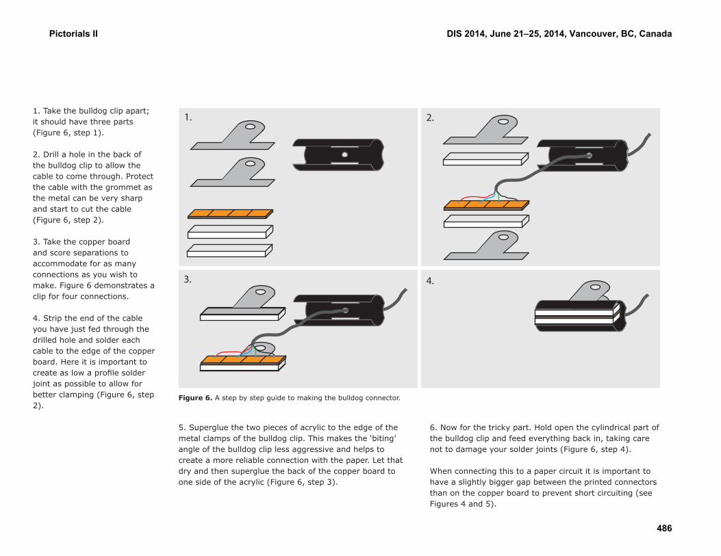
1. Take the bulldog clip apart; it should have three parts (Figure 6, step 1).
2. Drill a hole in the back of the bulldog clip to allow the cable to come through. Protect the cable with the grommet as the metal can be very sharp and start to cut the cable (Figure 6, step 2).
3. Take the copper board and score separations to accommodate for as many connections as you wish to make. Figure 6 demonstrates a clip for four connections.
4. Strip the end of the cable you have just fed through the drilled hole and solder each cable to the edge of the copper board. Here it is important to create as low a profile solder joint as possible to allow for better clamping (Figure 6, step 2).
Figure 6. A step by step guide to making the bulldog connector.
1. 2.
4.3.
5. Superglue the two pieces of acrylic to the edge of the metal clamps of the bulldog clip. This makes the ‘biting’ angle of the bulldog clip less aggressive and helps to create a more reliable connection with the paper. Let that dry and then superglue the back of the copper board to one side of the acrylic (Figure 6, step 3).
6. Now for the tricky part. Hold open the cylindrical part of the bulldog clip and feed everything back in, taking care not to damage your solder joints (Figure 6, step 4).
When connecting this to a paper circuit it is important to have a slightly bigger gap between the printed connectors than on the copper board to prevent short circuiting (see Figures 4 and 5).
Pictorials II DIS 2014, June 21–25, 2014, Vancouver, BC, Canada
486

PrintingScreen-printing (or silkscreen-printing) is one of the most cost effective methods for printing small runs of paper circuits without expensive machinery. The process involves the creation of a stencil on a fine woven mesh. Paint or ink is then pushed through this mesh onto a substrate to create a print. A screen-printed paper circuit allows for accuracy in terms of both trace layout and paint thickness; it is difficult to achieve such a high level of accuracy through painting or stencilling the paper circuit. Figures 7 and 8 show the screen-printing process.
We found that the water-based paint Bare Conductive worked well for screen-printing. Screen selection is important as carbon-based paint contains large carbon particles. Using a standard textile (90t) screen is more effective than a standard paper printing screen (300t) as the mesh on a textile screen has larger gaps between the filaments, allowing the paint to flow through the screen easily. A major issue that occurred when printing with Bare Conductive was that the paint dried quickly in the screen and therefore it was difficult to produce more than five prints before the print quality deteriorated rapidly. To overcome this, Bare Conductive was watered down to the ratio of one part water to nine parts Bare Conductive.
Figure 7. Screen-printing with Bare Conductive Figure 8. Screen-printing with Bare Conductive
Pictorials II DIS 2014, June 21–25, 2014, Vancouver, BC, Canada
487

With this adjustment, the paint did not dry so quickly in the screen and it was possible to make over 100 prints without having to clean the screen to prevent quality deterioration.
The conductive ink/water ratio is only the first important consideration when screen-printing with conductive ink. When designing paper circuits for screen-printing it is important not to make the traces too thin as the connection can easily be lost due to printing/paper imperfections. A line thickness of at least 2pt should be used to guarantee good connections. When printing sensors with long traces it may be worthwhile creating two connection traces in case one gets damaged or is poorly printed.
Paper stock choice also makes a difference to the successfulness of a paper circuit print. If a highly-textured paper stock is used, the paint may not flow into the deep troughs and connection issues would arise. Using a smooth stock eliminates this issue. It is also worthwhile printing on a stock that is at least 80gsm thick; a thinner stock tends to curl as the paint dries. Using a 200gsm non-textured stock gives reliable, consistent and robust results.
SensingConductive paint can be used to not only sense touch (capacitive touch), but also to sense humans from a distance. This distance-sensing uses the same principals as capacitive touch (where the electrical properties of the human body affect the capacitance of the printed sensing area). The printed sensor measures the capacitance of a human body whether it is in direct contact with the sensor or through a insulator (air) and finding earth (the ground). This means that there are variables that could affect the reading from the sensor: body mass, sweat, shoes and flooring to name a few. The following experiment was conducted by the lead author of this pictorial and explores the effect different grounding methods and printed sensor patterns have on sensor readings.
Figure 9. Sensor pattern #1 Figure 10. Sensor pattern #2
Figure 11. Sensor pattern #3 Figure 12. Sensor pattern #4
Figure 13. Sensor pattern #5 Figure 14. Sensor pattern #6
Pictorials II DIS 2014, June 21–25, 2014, Vancouver, BC, Canada
488

0
20
40
60
80
100
120
140
160
180
0 2 4 6 8 10 12
Ard
uino
Val
ue
Distance (cm)
Sensor pattern #1 Sensor pattern #2 Sensor pattern #3
Sensor pattern #4 Sensor pattern #5 Sensor pattern #6
0
50
100
150
200
250
300
0 2 4 6 8 10 12
Ard
uino
Val
ue
Distance (cm)
Shoes on with no grounding Shoes on, finger grounded to Arduino
Shoes on, Arduino grounded Shoes off, Arduino grounded
This experiment used an Arduino to measure the capacitance of the printed sensor. The testing circuit was based on Bare Conductive’s Building a Capacitive Proximity Sensor tutorial [2]. The circuit used a 1M Ohm resistor bridging across pins two and four of the Arduino, with pin two also connecting to the printed sensor.
We began this experiment with an investigation into the effect different printed sensor patterns had on the Arduino reading. Six different patterns were printed with Bare Conductive to create six different sensors (see Figures 9-14). Screen-printing was used to ensure a uniform thickness of conductive paint to allow for a fair comparison of sensors. The printed sensors were taped down in exactly the same spot on the workbench for testing and hand distance was measured as accurately as possible with a ruler (see Figures 15 and 16). Table 2 illustrates that the results from all six sensors behaved exponentially.
Figure 15. Experiment setup. Figure 16. Experiment setup.
Table 3. The effect of shoes and grounding with capacitive sensing.
Table 2. A comparison of printed sensor patterns with capacitive sensing.
Pictorials II DIS 2014, June 21–25, 2014, Vancouver, BC, Canada
489
SolderingConnecting components onto paper can be tricky. This pictorial will explore four methods; conductive epoxy, superglue, cold-soldering and conductive tape. Each of these four methods have their benefits and drawbacks depending on what components are being used and the complexity of the paper circuit.
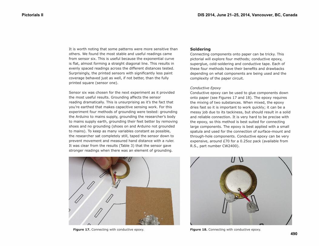
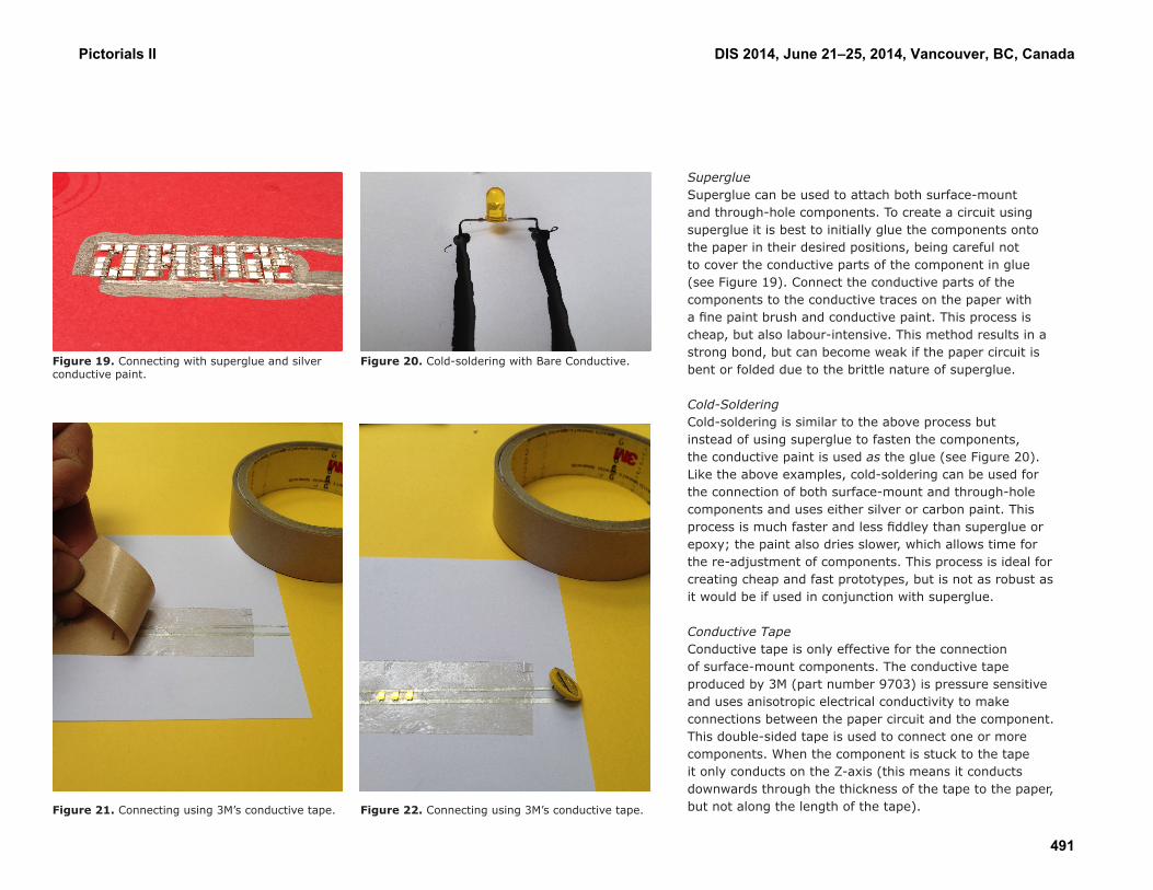
Conductive EpoxyConductive epoxy can be used to glue components down onto paper (see Figures 17 and 18). The epoxy requires the mixing of two substances. When mixed, the epoxy dries fast so it is important to work quickly; it can be a messy job due to its tackiness, but should result in a solid and reliable connection. It is very hard to be precise with the epoxy, so this method is best suited for connecting large components. The epoxy is best applied with a small spatula and used for the connection of surface-mount and through-hole components. Conductive epoxy can be very expensive, around £70 for a 0.25oz pack (available from R.S., part number CW2400).
Figure 17. Connecting with conductive epoxy.
It is worth noting that some patterns were more sensitive than others. We found the most stable and useful readings came from sensor six. This is useful because the exponential curve is flat, almost forming a straight diagonal line. This results in evenly spaced readings across the different distances tested. Surprisingly, the printed sensors with significantly less paint coverage behaved just as well, if not better, than the fully printed square (sensor one).
Sensor six was chosen for the next experiment as it provided the most useful results. Grounding affects the sensor reading dramatically. This is unsurprising as it’s the fact that you’re earthed that makes capacitive sensing work. For this experiment four methods of grounding were tested: grounding the Arduino to mains supply, grounding the researcher’s body to mains supply earth, grounding their feet better by removing shoes and no grounding (shoes on and Arduino not grounded to mains). To keep as many variables constant as possible, the researcher sat completely still, taped the sensor down to prevent movement and measured hand distance with a ruler. It was clear from the results (Table 3) that the sensor gave stronger readings when there was an element of grounding.
Figure 18. Connecting with conductive epoxy.
Pictorials II DIS 2014, June 21–25, 2014, Vancouver, BC, Canada
490
SuperglueSuperglue can be used to attach both surface-mount and through-hole components. To create a circuit using superglue it is best to initially glue the components onto the paper in their desired positions, being careful not to cover the conductive parts of the component in glue (see Figure 19). Connect the conductive parts of the components to the conductive traces on the paper with a fine paint brush and conductive paint. This process is cheap, but also labour-intensive. This method results in a strong bond, but can become weak if the paper circuit is bent or folded due to the brittle nature of superglue.
Cold-SolderingCold-soldering is similar to the above process but instead of using superglue to fasten the components, the conductive paint is used as the glue (see Figure 20). Like the above examples, cold-soldering can be used for the connection of both surface-mount and through-hole components and uses either silver or carbon paint. This process is much faster and less fiddley than superglue or epoxy; the paint also dries slower, which allows time for the re-adjustment of components. This process is ideal for creating cheap and fast prototypes, but is not as robust as it would be if used in conjunction with superglue.
Conductive TapeConductive tape is only effective for the connection of surface-mount components. The conductive tape produced by 3M (part number 9703) is pressure sensitive and uses anisotropic electrical conductivity to make connections between the paper circuit and the component. This double-sided tape is used to connect one or more components. When the component is stuck to the tape it only conducts on the Z-axis (this means it conducts downwards through the thickness of the tape to the paper, but not along the length of the tape).Figure 21. Connecting using 3M’s conductive tape. Figure 22. Connecting using 3M’s conductive tape.
Figure 19. Connecting with superglue and silver conductive paint.
Figure 20. Cold-soldering with Bare Conductive.
Pictorials II DIS 2014, June 21–25, 2014, Vancouver, BC, Canada
491

This means that multiple components stuck to the tape will only connect to the traces on the paper directly below them. They will not conduct along the tape to the other components, which would create a short circuit (see Figures 21 and 22). This is a very fast and easy way of connecting surface mount components to paper. The drawbacks of this method are that the tape can be very expensive (£193.42 per 32.9m roll) and it can only be used for surface-mount components, not through-hole components. This method will only work if your paper circuit has been printed with precision.
ConclusionThis pictorial has covered various simple techniques that allow for the printing, connection and soldering of paper circuits. A discussion of the available conductive paints explored their advantages and disadvantages. Two connecting methods were documented: the paper clip and the bulldog clip. A brief introduction to screen-printing with conductive paint highlighted important considerations to ensure successful printing. An exploration of the effects of printed sensor patterns and grounding was conducted. Finally, four methods of soldering were explained: conductive epoxy, superglue, cold-soldering and conductive tape.
Paper circuitry has the potential to radically change the way we interact and consume electronic products of the future. Everywhere we go in life we are surrounded by the amazingly ubiquitous paper; paper circuitry has the power to bring this rich craft material into the digital age. This pictorial’s low-tech craft approach to exploring the above-mentioned techniques should provide an accessible launch pad for anyone wishing to explore paper circuitry.
AcknowledgementsWe thank Novalia and the EPSRC for funding this research.
References[1] Buechley, L., Hendrix, S. and Eisenberg, M. Paints, paper, and programs: first steps toward the computational sketchbook. Proc. TEI 2009, ACM (2009), 9–12.[2] Building a Capacitive Proximity Sensor using Bare Paint, Instructables.com. URL http://www.instructables.com/id/Building-a-Capacitive-Proximity-Sensor-using-Bare-/ (accessed 3.19.14).[3] Coelho, M., Hall, L., Berzowska, J. and Maes, P. Pulp-based computing: a framework for building computers out of paper. Ext. Abstracts CHI 2009, ACM (2009), 3527–3528.[4] Kawahara, Y., Hodges, S., Cook, B.S., Zhang, C. and Abowd, G.D. Instant inkjet circuits: lab-based inkjet printing to support rapid prototyping of ubicomp devices. Proc. UbiComp 2013, ACM (2013), 363–372.[5] Shorter, M., Rogers, J., McGhee, J. Enhancing Everyday Paper Interactions with Paper Circuits. Proc. DIS 2014, ACM (2014).
Pictorials II DIS 2014, June 21–25, 2014, Vancouver, BC, Canada
492


![Cse III Electronic Circuits [10cs32] Notes](https://img.pdfslide.us/doc/110x75/5695d0ed1a28ab9b02947477/cse-iii-electronic-circuits-10cs32-notes.jpg)


![G7 - PRACTICAL CIRCUITS [3 exam question - 3 groups]](https://img.pdfslide.us/doc/110x75/56812a46550346895d8d8209/g7-practical-circuits-3-exam-question-3-groups.jpg)


