Embed Size (px)
Citation preview

Practical Limitations of Single-Span Ultra-HighPerformance Concrete Beams
by
Daniel Scott Abrams, E.I.T.B.S. Civil & Environmental Engineering
University of Massachusetts Amherst, 2012
( MASSACHUSETTS IN7TEOF TECHNOLOGY
JUL 0 8 2013
LBRARIES
SUBMITTED TO THE DEPARTMENT OF CIVIL AND ENVIRONMENTALENGINEERING IN PARTIAL
FULFILLMENT OF THE REQUIREMENTS FOR THE DEGREE OF
MASTER OF ENGINEERING IN CIVIL AND ENVIRONMENTAL ENGINEERINGAT THE
MASSACHUSETTS INSTITUTE OF TECHNOLOGY
June 2013
C2013 Daniel S. Abrams. All rights reservedThe author hereby grants to MIT permission to reproduce and to distribute publicly paper and
electronic copies of this thesis document in whole or in part in any medium now known orhereafter created.
Signature of Author:
Certified by:
Department of Civil and 1Evironmental EngineeringMay 24, 2013
Jerome J. ConnorProfe sor of Civil and Environmental Engineering
Thesi Supervisor
Accepted by:Hidi M. Nepf
Chair, Departmental Committee for Graduate Students


Practical Limitations of Single-Span Ultra-High Performance Concrete Beams
By
Daniel Scott AbramsSubmitted to the Department of Civil and Environmental Engineering on May 24, 2013
in Partial Fulfillment of the Requirements for the Degree of Master of Engineering in Civil andEnvironmental Engineering
ABSTRACT
Since its development in the early 1970's, researchers have continued to push the limits of
concrete mixtures through the creation of ultra-high performance concretes. The use of this class
of materials has allowed designers to build lighter and stronger structures, and in some cases has
allowed the construction of concrete members that do not require reinforcement. However, as
designers consider integrating and adapting these high performance materials into their
structures, they should be aware of the diminishing returns on the modulus of elasticity when
increasing the compressive strength of the mixture. While these UHPC mixtures have many
desirable qualities in relation to strength, durability, and longevity, designers should still be
aware of the pitfalls that result in the relationship between the compressive strength and modulus
of elasticity.
Thesis Supervisor: Jerome J. Connor
Title: Professor of Civil and Environmental Engineering


ACKNOWLEDGEMENTS
This thesis concludes my very full and rewarding higher education experience. Throughout this
journey, there have been a great number of people who have provided me with encouragement,
guidance, and support, and to whom I owe much appreciation and thanks.
First and foremost, I would like to thank Professor Jerome Connor for the inspiration,
knowledge, and wisdom he has bestowed upon me as my advisor. Without his guidance and
understanding, I would not have been able to complete this work and achieve my dream of
graduating MIT.
I would also like to thank every member of the course-1 M.Eng class of 2013 for their
companionship and friendship throughout this year. These nine months have been a truly
unforgettable experience, and working with this group has not just enriched my understanding of
engineering, but also of life.
Lastly, and perhaps most importantly, I would like to thank my loving family. Without their
support, devotion, and encouragement, I would surely not have been able to succeed at this great
institution. In particular, I would like to thank my dedicated mother, who has always been there
for me, even when I didn't ask. She has always driven me to be all that I can be, and without her
inspiration I would not have been able to achieve all the things that I have.


TABLE OF CONTENTS
Acknowledgem ents ......................................................................................................................... 5
Table of Contents............................................................................................................................ 7
List of Tables .................................................................................................................................. 8
List of Figures ................................................................................................................................. 9
1.0 Introduction....................................................................................................................... 11
2.0 Background ....................................................................................................................... 13
2.1 Evolution of Concrete .................................................................................................. 13
2.2 M odem Concrete Design ............................................................................................. 14
3.0 Review of Current Research ............................................................................................. 16
4.0 Sum m ary of Design requirem ents ................................................................................. 22
4.1 UHPC Concrete M aterial Properties........................................................................... 22
4.2 Lim it States ..................................................................................................................... 23
4.2.1 Strength Lim it State Design............................................................................... 23
4.2.2 Serviceability Lim it State Design ...................................................................... 24
5.0 Com parison of UHPC to Standard Concrete ................................................................. 27
6.0 Applications and Examples........................................................................................... 32
7.0 Conclusions....................................................................................................................... 35
References..................................................................................................................................... 37
7

LIST OF TABLES
Table 3-1. Typical UHPC Mixture Proportions......................................................................... 16
Table 4-1. Material Properties of FHWA UHPC...................................................................... 22
Table 5-1. Summary of Typical Values Used........................................................................... 28
Table 5-2. Compressive Strength of Various Concrete Mixtures............................................. 28
8

LIST OF FIGURES
Figure 2-1. Pantheon Interior .................................................................................................... 13
Figure 2-2. Typical Concrete M ix ............................................................................................ 15
Figure 3-1. Behavior of UHPC beams loaded until failure ..................................................... 17
Figure 3-2. Typical Reinforcem ent Fibers.................................................................................. 17
Figure 3-3. Optimal Pouring Method for UHPFRC ................................................................. 19
Figure 3-4. Cross-section of UH PFRC ...................................................................................... 20
Figure 3-5. Seonyu Bridge, Seoul, Korea.................................................................................. 21
Figure 5-1. Maximum Allowable Beam Length for Various Concrete Mixtures, d=b=1m ........ 29
Figure 5-2. Maximum Allowable Beam Length for Various Concrete Mixtures, b=4d=1m ...... 30
Figure 5-3. Maximum Allowable Beam Length for Various Concrete Mixtures, d=b/4=1m ..... 31
Figure 6-1. Pont Du Diable Footbridge, Herault, France .......................................................... 33
Figure 6-2. Sakata Mirai Footbridge, Yamagata, Japan .......................................................... 34
Figure 6-3. M ars H ill Bridge, Iow a, U SA ................................................................................. 35
9

10

1.0 INTRODUCTION
As a structural material, concrete is renowned for its compressive strength. Historically, concrete
has a compressive strength in the range of 20-40 MPa (3-6 ksi). However, as engineers continue
to push the boundaries of structural design, the size and complexity of reinforced concrete
structures has increased dramatically. To compensate for these increasingly complex engineering
demands, there is a pressing need for the development of higher strength and quality concrete.
In recent years, many researchers have developed different methods and mixtures for the creation
of ultra-high performance concrete (UHPC), which is defined as concrete with a compressive
strength exceeding 150 MPa (22 ksi) 7 3. In the early 1970s, a group of researchers in New York
developed a concrete mix with a compressive strength of 230 MPa (33 ksi) - an order of
magnitude greater than the current practice - by using pressure to increase the packing density of
the cement paste and conversely decreasing the porosity of the aggregate 221. Another research
group was able to achieve record high compressive strengths of 510 MPa (74 ksi) through the
application of intense heat and pressurel'5 l. However, it was not until the early 1990s that the
technology for creating such impressive mixtures became efficient enough to produce UHPC in
bulk quantity, although the processes were still somewhat complicated . In 2011, Wille et al.
published a paper detailing a method of mixing 150 MPa (22 ksi) concrete using a simple
method that did not involve the use of added pressure or heat. Their methods allow UHPC to be
mixed with conventional concrete mixing methods and equipment, making it much more
efficient to produce and deliver.
11

The use of these types of UHPC allows structural engineers to challenge previously established
limitations in structural design. The increased compressive strength can allow members to be
lighter and more slender while maintaining the same nominal load capacity. However, as these
elements become more slender, the limiting factor in the design ceases to be the cracking,
buckling, or yielding of these elements, but rather the dynamic serviceability requirements.
Slender elements are more susceptible to experiencing significant vibrations during dynamic
loading conditions. Thus, this thesis will explore the practical limitations of UHPC beam design
under dynamic loading conditions, with the goal of developing a relationship between the
compressive strength, moment of inertia, and length of a beam in relation to both failure and
serviceability requirements. A brief history of reinforced concrete design, as well a summary on
the current research into the structural performance of UHPC beams and frames is included.
Lastly, the development of a practical relationship will be accomplished through careful analysis.
The paper will conclude with the results of these analyses.
12

2.0 BACKGROUND
2.1 Evolution of Concrete
From its primitive development by the ancient Greeks in 800 BCE, cement has been a key
material in the design and construction of many buildings, bridges, and other structures. The
simplistic mixture of lime and gypsum sand was used extensively in ancient infrastructure. Even
this most basic cement mixture had such nearly unparalleled strength, durability, and longevity
for its time; in fact, many of these ancient structures still stand today. The Roman Pantheon, seen
below in Figure 2-1, is one such example. In some cases, this archaic concrete mixture had
comparable compressive strength to modem Portland-cement concrete[3]
Figure 2-1. Pantheon Interior
While the concrete of ancient Greece and Rome had remarkable compressive strength, it bears
very little other resemblance to Portland cement. The design of cement advanced at a crawling
pace until 1824, when British bricklayer Joseph Aspdin developed the first Portland cementE"1.
13

Aspdin's cement mixture quickly became the basis for virtually all structural concrete, and the
current recipe is still a derivative of the original. This new mixture was a significant
improvement on Roman cement, primarily due to its plasticity before curing, allowing it to be
poured on site as a homogenous fluid rather than being hand layered, as well as advances and
standardization of the aggregate materialsf81 .
The next major improvement in the design of concrete came from the introduction of metal
reinforcement bars, called re-bar. The addition of re-bar, which was originally made of iron,
greatly increased the tensile strength of the concrete. Prior to its introduction, concrete was weak
in tension as its only method for resisting these forces was through the relatively weak bonds
within the concrete. Iron reinforcing was first patented in 1854 by an English plasterer William
B. Wilkinson, when he used iron bars and wire ropes in the construction of the floors of a small,
two-story cottage. Wilkinson was the first person to recognize the need of reinforcement on the
tension side of the beams and postsf'61 . Today, reinforcement bars are made from high strength
structural steel. The sizes and material properties of re-bar are standardized by American Society
for Testing and Material, or ASTMI'].
2.2 Modern Concrete Design
In general, structural concrete is made from a mixture of Portland cement, various aggregates,
and water. Due to the nature of the way concrete is mixed, there is also some air entrained within
the mixture. The goal in making a concrete mixture is to produce a strong, durable product when
hardened that has enough workability to be easily poured and molded. The key to effectively
achieve this is in the correct proportioning of components. A typical concrete mixture, like one
14

you might buy in a ready to mix bag at the hardware store, can be seen below in Figure 2-211.
This type of concrete is known as regular concrete.
11% Poland Cement
41%Gravel or Cnmsd Sbone(Coerse Agisegt)26% Sand (ne AggrgaW)
Figure 2-2. Typical Concrete Mix
Concrete is generally classified by its compressive strength, f'c. This value depends heavily on
the size, type, and proportions of the different aggregates, as well as the volume entrained air and
water to cement ratio. ASTM provides guidelines for classifying the different types and sizes of
aggregates, and gives methods for calculating the compressive strength of basic concrete
mixtures. The compressive strength of concrete can vary between 20-40 MPa (3-6 ksi) for
regular concrete. Typically, a building or bridge construction will call for 28 MPa (4 ksi)
strength concrete"1 . UHPC, however, can have compressive strength as high as 510 MPa (74
ksi), but more typically in the range of 150-200 MPa (22-29 ksi). Additionally, this higher
quality concrete has improved durability, freeze-thaw resistance, as well as many other desirable
attributes. This significant increase in quality can be attributed to the addition of various
chemical additives and different mixing procedures. These procedures include vacuum mixing,
applying high temperatures and pressures during mixing, and decreasing the water to cement
rt [20]ratio
15

3.0 REVIEW OF CURRENT RESEARCH
Ultra-high performance concrete is any concrete mixture that has a compressive strength in
excess of 150 MPa (22 ksi). In general, UHPC is denser than normal strength concrete, and can
often be characterized by lower water to cement or water to binder ratios. Unlike normal strength
concrete, UHPC includes special ingredients to increase its strength, including silica fume, glass
powder, and high-range water reducing admixtures [71. The silica fume is used to fill the
micropores and reduce the porosity. The water reducer helps lower the w/c ratio. A typical
UHPC mixture can be seen in Table 3-1[.
Table 3-1. Typical UHPC Mixture Proportions
Component Mixture Proportionsby Weight
Portland Cement 1.00Silica Fume 0.25
Glass Powder 0.25Water 0.18
High-range water 0.0114reducing admixture
Sand 1.05
When loaded to failure, the load-deflection curve for UHPC beams can be categorized by five
significant events, categorized in Figure 3-1, below1121 . As the load is quasi-statically applied, the
concrete follows a linear stress-strain relationship, until the concrete first experiences cracking,
labeled A. The stress-strain relationship remains somewhat linear until the steel yields at the
ultimate load, labeled B. The yielded steel plastically deforms until the concrete begins to crush
at point C. With the concrete failure, it begins to disintegrate from the reinforcement steel, until,
at C', the steel is exposed. Finally, the beam continues to behave plastically until the
reinforcement bars fracture and the concrete fails.
16

Figure 3-1. Behavior of UHPC beams loaded until failure
Despite being able to achieve very impressive compressive strengths, the tensile strength of
UHPC is generally limited to around 8 MPa (1.2 kips). However, just as in commercial
reinforced concrete, the addition of steel greatly improves the tensile strength of the UHPC
mixture. Advancements in the design of the UHPC mixes have allowed researchers to begin to
create concrete members that do not require traditional steel reinforcement bars. Instead, these
ultra-high performance fiber reinforced concrete (UHPFRC) members feature concrete with
uniformly distributed concrete fibers.
(a) straight (S) (b) hooked (H) (c) twisted (T)
Figure 3-2. Typical Reinforcement Fibers
17

Figure 3-2 shows typical reinforcement fibers. These fibers vary in dimension and can feature
hooked ends or twisting along their length. The different styles of reinforcement fibers each
create different UHPFRC with varying structural properties and applications. These can be
categorized into three primary types. Type 1 UHPFRC generally contains 5-10% short steel
fibers, less than 6 mm (0.24 in) in length. This type of reinforcement improves tensile
performance, but does not aid in ductility. Therefore, traditional reinforcement bars are still
needed' 41. In structures, ductility is needed to prevent sudden brittle fractures of the concrete
members. Type 2 UHPFRC aims to add ductility by including smaller proportions - typically 2-
3% by volume - of longer steel fibers. These fibers can range in length from 13-20 mm (0.51-
0.79 in) long, and are typically twisted along their length. In some cases, these fibers can replace
some or all of the reinforcement within the UHPC ' 4]. The inclusion of traditional reinforcement
bars in concrete construction can significantly add to the time, cost, and difficulty of
construction. Thus, it is desirable to use UHPFRC mixtures that can completely replace
traditional reinforcement, which can be done with Type 3. This type of mixture included high
proportions - up to 11% - of fibers that range in length from 1 mm (0.04 in) to 20 mm (0.79
in)[ 4 . Much like Type 2, the tensile strength and ductility of the UHPC is increased, and to such
an extent that it could make traditional reinforcement obsolete.
The improvement in ductility can be quantified with the ductility index, Id. Ductility index is a
quantity derived from the stress-strain curve and modulus of elasticity of a material, with the
relationship shown in the equation below.
Id = Ep/(
18

Ordinary and ultra-high performance concrete mixtures have a ductility index of 1. Type 2
UHPFRC has an index ranging from 1.5 to 3, and type 3 UHPFRC has a ratio that is an order of
magnitude higher, at 17.5 to 30. As a frame of reference, the ductility index of steel ranges from
30 to 6011.
However, these fibers only significantly improve the tensile strength and ductility of UHPC if
they are aligned parallel with the tensile stresses within the member. Therefore, it is important to
control the orientation of these fibers when pouring the concrete.
top view
fast
+ -/ -- moverpentmed.
slow
+-flsw direction
Figure 3-3. Optimal Pouring Method for UHPFRC
Improper fiber orientation can cause significant negative strength variations within the concrete.
For optimal orientation, the UHPFRC should be poured very quickly from a long chute pitched
at approximately 30 degrees. The chute should be drawn across the cast, in the direction of the
tensile loading, creating thin layers until the form is completel1 91. By using a long chute and fast-
flowing concrete, the fibers within the'mixture are able to orient in the direction of the chute,
resulting in an optimal reinforcement fiber pattern. Moving the chute too slowly can cause a
"snaking" of the concrete, which leads sub-optimally oriented fibers. This layer casting method
19
can be seen in Figure 3-3[191. Figure 3-4 shows a cross section of a beam that has been cast this
way171 . Although there is some exposed steel, superficial corrosion does not lead to any
significant loss in strength or ductility of the member 41.
Figure 3-4. Cross-section of UHPFRC
In addition to having more compressive strength, UHPC has other advantages over regular
concrete. Some researchers have found that UHPC responds very favorably to freeze-thaw cycles
by not experiencing any deterioration in material properties, and in some cases having improved
the long-term material properties when compared to a control[71. UHPC also is more durable than
its normal performance counterpart, both in quasi-static loading and dynamic loading
[101conditions
20

Companies are beginning to patent and produce their own brands of UHPC. One such
commercialized mixture, called Ductal@, was developed by the French construction material
manufacturing firm, Lafarge. Their new product is an UHPC blend utilizing a natural mineral
matrix and reinforced with both organic and metallic fibers. The company claims that their
product has "superior qualities in terms of resistance to compression, ductility, and longevity."
By utilizing Ductal@ in their designs, engineers can reduce material, labor, framework, and
maintenance costs, all while improving the safety and speed of construction141. Ductal@ has been
used in a number of structures, ranging from highway and footbridges to building facades and
roofing. One such example, the Seonyu Bridge in Seoul, Korea, can be seen in the figure
belowE41 .
Figure 3-5. Seonyu Bridge, Seoul, Korea
21

4.0 SUMMARY OF DESIGN REQUIREMENTS
4.1 UHPC Concrete Material Properties
In the late 2009, The Federal Highway Administration began to implement UHPC into their
bridge construction practice, both in prefabricated and field-cast sections. The material property
standards for this concrete mixture 51 can be seen in Table 4-1, below.
Table 4-1. Material Properties of FHWA UHPC
Property Value158 lb/ft3
Unit Weight/Density 23 gm2535 kg/m37500-8500 ksi
Modulus of Elasticity 52-5 9 p52-59 Gpa25-32 ksi
Compressive Strength 170-220 Mpa
In general, the modulus of elasticity of concrete (in MPa) can be approximately calculated using
the equation from the ACI code11 , listed below:
Ec = 0.043 w,/-
However, in the case of UHPC, this relationship is not valid as it is empirical and intended only
for normal weight and density concrete. Instead, the value for the modulus of elasticity must be
determined through laboratory testing. For the purposes of the analysis in this report, the material
properties in Table 4-1 will be used. The equation is still of some use, as it shows the relationship
between compressive strength and modulus of elasticity can be characterized by E oc If7.
Thus, there are diminishing returns on the Young's modulus with successive increases in the
compressive strength.
22

4.2 Limit States
In concrete design, the structure must be able to accommodate the various limit states which may
be encountered. The limit state is the point at "which a structure or part of a structure ceases to
perform its intended function."191. This can be caused by structural failure at ultimate strength or
by serviceability limitations.
4.2.1 Strength Limit State Design
Also known as the ultimate limit state, this is the state at which a member experiences structural
failure, generally by exceeding the maximum allowable stress in the materialW'8 1. For a reinforced
concrete beam in bending, this occurs when the compression concrete or the tensile
reinforcement reaches its yield stress. The bending stress, a, is defined as the ratio of the bending
moment to the section modulus. For any given member, this value must be less than the
maximum allowable stress, a*. This relationship can be expressed through the following
equation:
Mdcy <cr
21 -
where M is the maximum bending moment in the section, d is the section depth, and I is the
modulus of elasticity of the material. For a simply supported beam under uniform loading, the
maximum moment, located at midspan, can be determined through basic statics. Substitution into
the stress equation yields an expression for the maximum allowable stress for a beam of length L
under the total uniform loading distribution, WT.
WTL 2d
161
23

Solving this equation for the moment of inertia yields an expression for the minimum moment of
inertia required for strength design for a section.
IU > T2d- 16-*
Where WT = WD + WL, which are the dead and live load distributions, respectively.
4.2.2 Serviceability Limit State Design
In structural design, serviceability is just as vital as strength for a successful structure.
Serviceability refers to the conditions under which a structure is still able to perform its intended
function. These factors, which are equally as important as the member strength, include things
such as excessive deflection, detrimental cracking, or excessive amplitude or undesirable
frequency of vibrationf'8 1 .
For this study, the deflection and frequency of vibration serviceability limit states will be
investigated. The midspan deflection, u, of a simply supported beam is categorized by the
following equation:
SWLL< L
f 384EI a
Where a is a code-specified factor, E is the modulus of elasticity of the material, and all other
variables are previously defined. Only the live load is taken into account because the dead load
deflection can be accounted for by cambering the beam. The value of a varies with the code and
application, but a typical value is 240 for floor beams under combined loading 61 . Solving this
equation for the required moment of inertia yields an expression for the minimum moment of
inertia required for the deflection limit state.
24

>a_ - 384E
In addition to these static requirements, a structure must also not experience excessive vibrations,
both in amplitude and period length. Vibrations can be introduced to a structure through many
sources, ranging from wind and seismic loading to pedestrian and vehicular use. The frequency
and period of these vibrations must not be excessive or, despite being structurally stable, the
structure may not feel safe to the user. The modal frequency, w, for a simply supported beam is
given by the following equation[2 :
2 EI 4
pm -
where p,, is the density of concrete (per unit length) and wv* is the allowable modal frequency,
and all other variables are previously defined. As with the equations for both maximum stress
and deflection serviceability, this equation can be rearranged into similar form.
pmL4
Typical values of wv* are specified by the code and depend on the usage of the structure, but for
simple bridge structures range from 7.9-14.5 rad/s. These correspond to a natural period of less
than one second (T, < 1), and natural frequencies,f, ranging from 1.25-2.3 Hz.
To determine which of these serviceability requirements controls the value of the moment of
inertia of the section, the ratio of the two values, r, can be taken. The mass density of the
concrete can be converted to the dead load of the beam structure by multiplying the equation by
the identity value of the ratio of gravity over gravity (g/g).
I" iS4ga WL
r 384Lw*2 WD)
25

Setting r = 1 and solving for the frequency, we obtain:
51w4 ga WL)384 L WD
When oY* > *|icr, the live load displacement serviceability criteria controls the value of I.
However, with lower frequency values, the period of vibration Tn, controls the design. For a
pedestrian bridge, it is desirable to have a short period with high frequency, so the user does not
feel uneasy when traversing the structure.
26
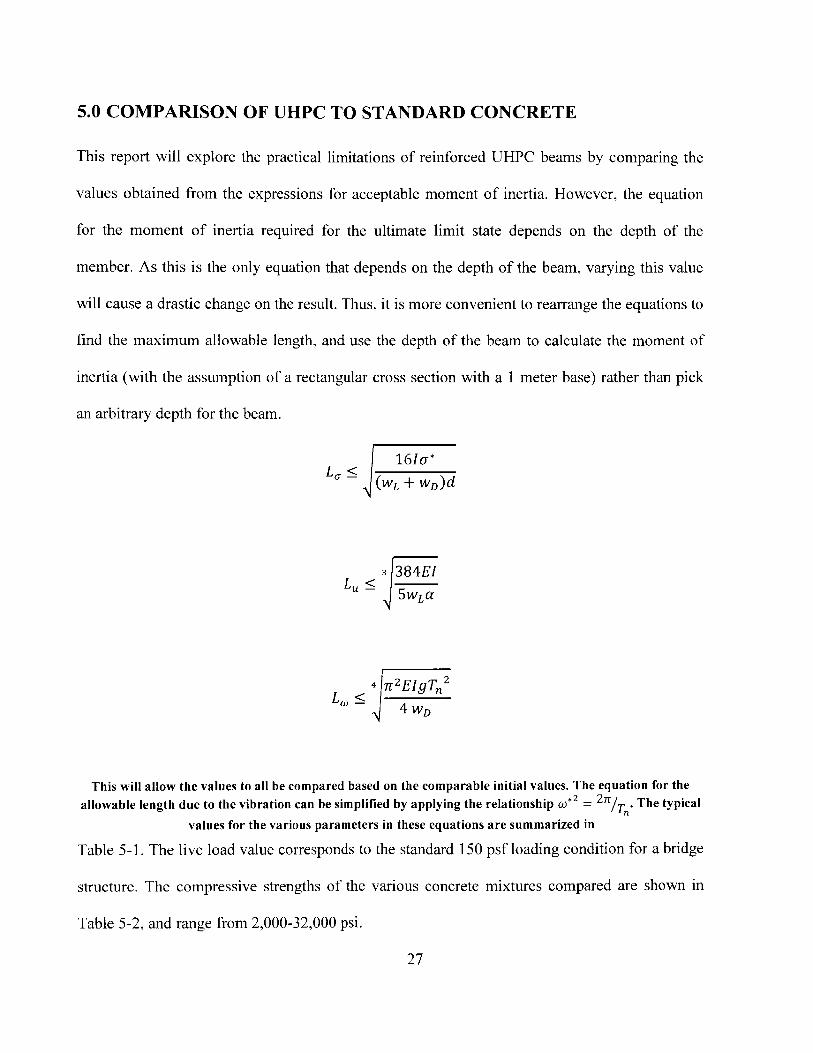
5.0 COMPARISON OF UHPC TO STANDARD CONCRETE
This report will explore the practical limitations of reinforced UHPC beams by comparing the
values obtained from the expressions for acceptable moment of inertia. However, the equation
for the moment of inertia required for the ultimate limit state depends on the depth of the
member. As this is the only equation that depends on the depth of the beam, varying this value
will cause a drastic change on the result. Thus, it is more convenient to rearrange the equations to
find the maximum allowable length, and use the depth of the beam to calculate the moment of
inertia (with the assumption of a rectangular cross section with a 1 meter base) rather than pick
an arbitrary depth for the beam.
16c-*
(wL + wD)d
3 384EI
5 wLUL~ SWLcC
< 4rzEIgTz
4 WD
This will allow the values to all be compared based on the comparable initial values. The equation for the
allowable length due to the vibration can be simplified by applying the relationship o)*2 =
2 /T . The typical
values for the various parameters in these equations are summarized in
Table 5-1. The live load value corresponds to the standard 150 psf loading condition for a bridge
structure. The compressive strengths of the various concrete mixtures compared are shown in
Table 5-2, and range from 2,000-32,000 psi.
27

Table 5-1. Summary of Typical Values Used
WL 4788 Pa
a 240
g 9.81 m/s 2
T, 1.00 sec
Table 5-2. Compressive Strength of Various Concrete Mixtures
Imperial Strength Metric Equivalent
2.0 ksi 14 MPa
2.5 ksi 18 MPa
3.0 ksi 20 MPa
3.5 ksi 25 MPa
4.0 ksi 30 MPa
5.0 ksi 35 MPa
6.0 ksi 40 MPa
7.0 ksi 50 MPa
8.0 ksi 55 MPa
10.0 ksi 70 MPa
25.0 ksi* 170 MPa*
32.0 ksi* 220 MPa*
*UHPC Mixtures
For the UHPC mixtures, the weight and modulus of elasticity values can be found in Section 4.1
of this report. For the normal strength concrete mixtures, the modulus of elasticity can be
calculated using the equation mentioned prior in this report. The typical weight of normal
strength concrete is 150 pcf (2400 kg/m 3).
Figure 5-1 shows how the simply-supported beam length increases with increasing compressive
strength for each criterion. This figure uses the values in the two tables above, and assumes the
beam has a base and depth of 1 meter by 1 meter, and thus a moment of inertia of 0.083 M4 .
28

250
- Ultimate L.S.'- - Ultimate L.S. for UHPC
E - Deflection Serviceability L.S.200 - Deflection Serviceability L.S. for UHPC
- Vibration Serviceability L.S.-- Vibration Serviceability L.S. for UHPC
0
>150
0
E
00 50 100 150 200 250
Compressive Strength of Concrete (MPa)
Figure 5-1. Maximum Allowable Beam Length for Various Concrete Mixtures, d=b=1m
For comparison, the above figure shows both the allowable length that the standard empirical
equation would yield as well as the lengths based from the actual values of the UHPC. For the
ultimate limit state, the value follows the same prediction, as this condition does not depend on
the modulus of elasticity. However, for both the deflection and vibration serviceability cases the
actual allowable lengths are notably lower than those predicted by the empirical equation. This
supports the previous claim that the empirical equation for the modulus elasticity of concrete
does not hold true for UHPC. As the compressive strength of the concrete increases, there are
diminishing returns in regards to the modulus of elasticity, and therefore in the allowable length
29

of a single-span beam. The length is expected to plateau due to the empirical relationship stated
in Section 4.1, however this effect occurs at a lower value than would have been predicted with
the aforementioned relationship. Thus, there are practical limitations on what levels of UHPC are
recommended for any given span. In many cases, the difference in limit states for standard and
UHP concrete is negligible, and UHPC should instead be considered primarily for its other
benefits and superior qualities.
70 -Ultimate L.S.E - Ultimate L.S. for UHPC6S
6 - Deflection Serviceability L.S.-- Deflection Serviceability L.S. for UHPC- -- Vibration Serviceability L.S.
0CL -Vibration Serviceability L.S. for UHPC
40E(A~ 40%0 30
20E 130
0: 20
E 10
010 50 100 150 200 250
Compressive Strength of Concrete (MPa)
Figure 5-2. Maximum Allowable Beam Length for Various Concrete Mixtures, b=4d=lm
Varying the beam depth (and thus the moment of inertia) changes whether the
displacement or vibration serviceability limit state (L.S.) controls the design.
30

Figure 5-2 shows the effect of making the cross-section flatter, with the dimensions
corresponding to a depth of 0.25 meters (d = b/ 4 ). Much like the square cross section,
displacement serviceability controls the design.
Similarly, Figure 5-3 shows the effect of increasing the section depth to 4 meters (d = 4b). With
a deep section, the vibration serviceability requirement begins to take control of the design.
600 - Ultimate L.S.E - Ultimate L.S. for UHPC
-rW - Deflection Serviceability L.S.
500 -Deflection Serviceability L.S. for UHPC-Vibration Serviceability L.S.
0C.
E
0
.0
0
EE(U
- Vibration Serviceability L.S. for UHPC
400
E 300
200
100
50 100 150
Compressive Strength of Concrete (MPa)
200 250
Figure 5-3. Maximum Allowable Beam Length for Various Concrete Mixtures, d=b/4=1m
These conclusions have been drawn with the assumption that the beam width is 1 meter. While
these conclusions are representative of the trends, the actual values need to be calculated for each
different beam width.
31
0 -0

6.0 APPLICATIONS AND EXAMPLES
The concepts discussed in this thesis have many practical applications. Namely, the design
recommendations can be directly applied to UHPC bridge structures, especially those that are
single-span. Architects and engineers around the world are beginning to experiment with
designing concrete bridges that are exceptionally strong and lightweight. By using UHPC, these
designers are able to create simply-supported spans of unprecedented length for their structural
system.
Figure 6-1. Pont Du Diable Footbridge, Hrault, France
One such example of this type of bridge structure is Pont Du Diable (Devil's) Footbridge,
located in the gorges of Herault, France. Designed by architect Rudy Ricciotti in 2008, this
bridge is the first UHPC footbridge in Europe. The structure consists of identical precast
Ductal@ I-beam sections, which were assembled on-site to create a pair of statically determinate
beams to support the footbridge deck over its 230 foot (70 meter) span. These beams also act as
the safety rails, giving the bridge a very thin, light, and minimalist profile. The use of the
Ductal@ UHPC allowed the beam pairs of the bridge to achieve an ultra-high slenderness ratio,
32

with a constant 6 feet (1.8 meters) of depth over the entire bridge. However, due to the single-
span nature of the bridge, it does require additional tuned mass dampers to prevent excessive
footfall vibrationE'3 .
Figure 6-2. Sakata Mirai Footbridge, Yamagata, Japan
The Sakata Mirai Footbridge, spanning 50 meters over the the Niita River in Yamgata, Japan, is
another Ductal@ footbridge. It replaced an old standard strength concrete bridge in the same
location. UHPC was chosen primarily for its resistance to varying temperatures, as this region
experiences hot summers and cold winters [41. The use of the UHPC in the new design allowed
the engineers to create an extremely thin profile, with the top slab thickness of the box girder
being less than 5 cm and a wall thickness of 8 cm, with numerous circular perforations
33

throughout the web. The most remarkable feature, however, is the complete lack of passive steel
reinforcement bars, even in the pre-stressing anchorage 1 71 . This bridge was also the first use of
UHPC in Japan [4].
Although it is not a footbridge, the first Ductal@ bridge in North America is a highway bridge
located in Wapello County, Iowa. This bridge was commissioned by the FHWA and the Iowa
DOT and constructed under the Innovated Bridge Construction Program. The bridge features
three single-span concrete girders just over 110 feet in length (33.5 meters) to support the bridge
deck. The most striking thing about this bridge, however, is not the span or scale, but rather the
lack of traditional shear reinforcement (stirrups). The integrated fiber reinforcement provides
adequate shear resistance, and this bridge stands as a functional proof-of-concept for UHPFRC.
Additionally, the UHPFRC deck has absolutely no rebar, relying on the fiber reinforcement to
carry all induced shear and tension 41.
Figure 6-3. Mars Hill Bridge, Iowa, USA
34

7.0 CONCLUSIONS
In recent years, researchers have continued to push the limits of concrete mixtures through the
creation of ultra-high performance concretes. As designers consider integrating and adapting
these high performance materials into their structures, they should be aware of the diminishing
returns on the modulus of elasticity when increasing the compressive strength of the mixture.
The increase in strength is actually even less than would be expected from current empirical
equations utilized by the ACI code. While these UHPC mixtures have many desirable qualities in
relation to strength, durability, and longevity, designers should still be aware of the pitfalls that
result in the relationship between the compressive strength and modulus of elasticity.
35

36

REFERENCES
1. Building Code Requirements for Structural Concrete (ACI 318-11) and Commentary.Farmington Hills, MI: American Concrete Institute, 2011. Print.
2. Connor, J. J. Introduction to Structural Motion Control. Upper Saddle River, NJ: PrenticeHall Pearson Education, 2003. Print.
3. Cowan, Henry J. Introduction. The Master Builders: A History of Structural andEnvironmental Design from Ancient Egypt to the Nineteenth Century. New York: Wiley,1977. 54. Print.
4. Ductal. "Lafarge Ductal." Lafarge Ductal, n.d. Web. 19 May 2013.5. Graybeal, Ben. "Field-Cast UHPC Connections for Modular Bridge Deck Elements."
Fhwa.dot.gov. FHWA, Nov. 2010. Web. 06 May 2013.6. International Building Code: 2012. Country Club Hills, IL: International Code Council,
2012. Print.7. Magureanu, Cornelia, Iona Sosa, Camelia Negrutiu, and Bogdan Heghes. "Mechanical
Properties and Durability of Ultra-High-Performance Concrete." A CI Materials Journal109.2 (2012): 177. Print.
8. Mark, Robert, and Paul Hutchinson. "On the Structure of the Roman Pantheon." Art Bulletin68.1 (1986): 26. Print.
9. McCormac, Jack C., and Russell H. Brown. Design of Reinforced Concrete. Hoboken, NJ:John Wiley, 2009. 58. Print.
10. Parant, Edouard, Pierre Rossi, Eric Jacquelin, and Claude Boulay. "Strain Rate Effect onBending Behavior of New Ultra-High-Performance Cement-Based Composite." ACIMaterials Journal 104.5 (2007): 458. Print.
11. "Portland Cement Association." Cement.org. PCA, 2013. Web. 06 May 2013.12. Rashid, M.A., and M.A. Mansur. "Reinforced High-Strength Concrete Beams in Flexure."
ACI Structural Journal 102.3 (2005): 462. Print.13. Ricciotti, Rudy. "Pont Du Diable." Rudyricciotti.com. Rudy Ricciotti Archietcture, n.d. Web.
19 May 2013.14. Rossi, Pierre. "Ultra High-Performance Concretes." Concrete International 30.2 (2008): 31-
34. Print.15. Roy, D., G. Gouda, and A. Bobrowsky. "Very High Strength Cement Pastes Prepared by Hot
Pressing and Other High Pressure Techniques." Cement and Concrete Research 2.3 (1972):349-66. Print.
16. Shaeffer, R. E. "History of Concrete Building Construction." Reinforced Concrete:
Preliminary Design for Architects and Builders. New York: McGraw-Hill, 1992. N. pag.
Print.17. Tanaka, Y., H. Musha, S. Tanaka, and M. Ishida. "Durability Performance of UFC Sakata-
mira Footbridge under Sea Environment." Fracture Mechanics of Concrete and Concrete
37

Structures - High Performance, Fiber Reinforced Concrete, Special Loadings and StructuralApplications. N.p.: Korea Concrete Institute, 2010. 1648-654. Print.
18. Wang, Chu-Kia, Charles G. Salmon, and Jos6 A. Pincheira. Reinforced Concrete Design.Hoboken, NJ: John Wiley & Sons, 2007. Print.
19. Wille, Kay, and Gustavo J. Parra-Montesinos. "Effect of Beam Size, Casting Method, andSupport Conditions on Flexural Behavior of Ultra-High-Performance Fiber-ReinforcedConcrete." A CI Materials Journal 109.3 (2012): 379. Print.
20. Wille, Kay, Antoine E. Naaman, and Gustavo J. Parra-Montesinos. "Ultra-High PerformanceConcrete with Compressive Strength Exceeding 150 MPa (22 Ksi): A Simpler Way." ACIMaterials Journal 108.1 (2011): 46-54. Print.
21. Wille, Kay, Antoine E. Naaman, and Sherif El-Tawil. "Optimizing Ultra-High-PerformanceFiber-Reinforced Concrete." Concrete International 33.9 (2011): 35. Print.
22. Yudenfreund, M., I. Odler, and S. Brunauer. "Hardened Portland Cement Pastes of LowPorosity I. Materials and Experimental Methods." Cement and Concrete Research 2.3(1972): 313-30. Print.
38