Embed Size (px)
Citation preview
MXProUser Guide
STATEMENT OF WARRANTY
Videonics, Inc. warrants this product against defects in materials or workmanship as follows:
For a period of TWO years from the date of purchase, Vide-onics Inc. will repair or replace the unit, at our option, with-out charge for parts or labor. After the period of TWO years you must pay all parts and labor charges.
The limited warranty is extended only to the original pur-chaser and is valid only to consumers in the United States and Canada. It does not cover damage or failure caused by or attributable to Acts of God, abuse, misuse, improper or abnormal usage, faulty installation, improper maintenance, lightning, or other incidences of excessive voltage, or any repairs or tampering by other than a Videonics-authorized repair facility. It does not cover replacement of batteries or other consumable parts, transportation costs, or damage in transit. This warranty will become void if the serial number or model number identification has been wholly or partially removed or erased. Repair or replacement under the terms of this warranty do not extend the terms of this warranty. This warranty can not be modified by any agent of Videonics, Inc. unless in writing and signed by an officer of Videonics, Inc.
Should this product prove defective in workmanship or material, the consumer's sole remedies shall be such repair or replacement as provided by the terms of this warranty. Under no circumstances shall Videonics, Inc. be liable for any loss or damage, direct, consequential, or incidental, aris-ing out of the use of or inability to use this product. Some states do not allow limitations on how long an implied war-ranty lasts or the exclusions or limitations of incidental or consequential damages, so the above limitations or exclu-sions may not apply to you. This warranty gives you specific legal rights. You may also have other rights which vary from state to state.
To obtain warranty service, call or write Videonics HelpLine for a Return Authorization (RA) number. Please mark the RA number clearly on the outside of the package. Include a copy of your sales receipt, a brief description of the symp-toms, your name, address, phone number and any special shipping instructions. Then deliver or ship the product, postage or shipping costs prepaid, to a Videonics-authorized repair facility. For the name of the nearest repair facility, Contact Videonics, Inc. HelpLine. See “Contacting Videon-ics” on page 8 for instructions.
DISCLAIMER
Television screens are simulated and subject to change with-out notice. This device is not to be used for the unautho-rized copying of copyrighted material.
TRADEMARKS
MX-Pro, the Videonics logo, Thumbs Up, MX-1, and Vide-onics Video TitleMaker are trademarks or registered trade-marks of Videonics, Inc. Hi8 is a trademark of Sony Corporation. VHS is a registered trademark of JVC. Other product and brand names might be trademarks or registered trademarks of their respective companies and are hereby acknowledged.
FCC Statement
This equipment has been tested and found to comply with the limits for a Class A digital device, pursuant to part 15 of the FCC Rules. These limits are designed to provide reason-able protection against harmful interference when the equipment is operated in a commercial environment. This equipment generates, uses, and can radiate radio frequency energy and, if not installed and used in accordance with the instruction manual, might cause harmful interference to radio communications. Operation of this equipment in a residential area is likely to cause harmful interference, in which case the user must correct the interference at his/her own expense.
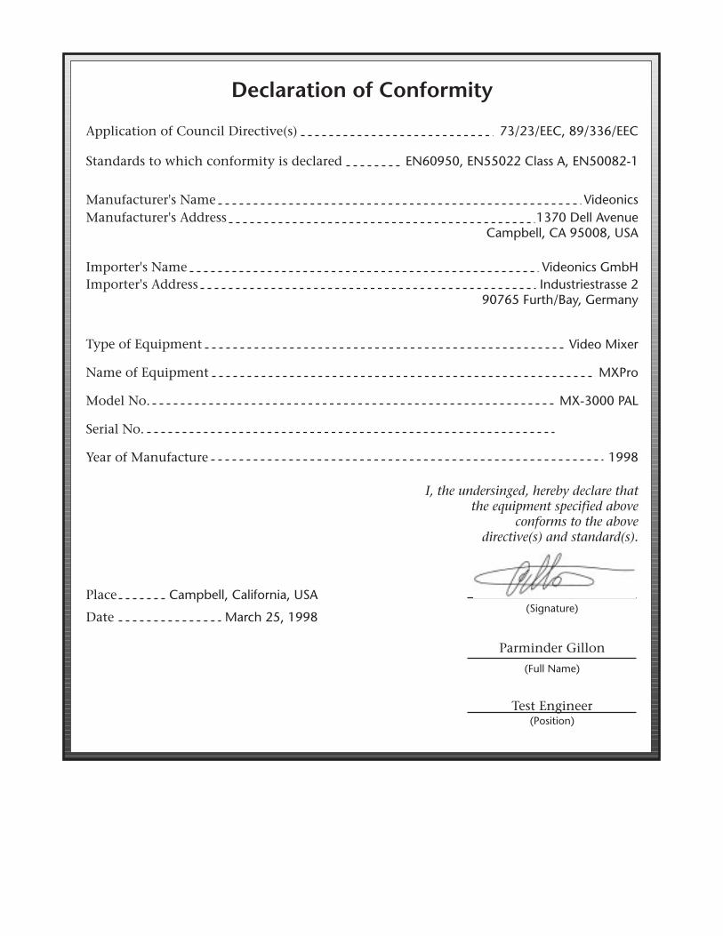
Declaration of Conformity
Parminder Gillon
Test Engineer
I, the undersinged, hereby declare thatthe equipment specified above
conforms to the abovedirective(s) and standard(s).
(Signature)
(Full Name)
(Position)
Application of Council Directive(s) 73/23/EEC, 89/336/EEC
Standards to which conformity is declared EN60950, EN55022 Class A, EN50082-1
Place Campbell, California, USA
Date March 25, 1998
Manufacturer's Name VideonicsManufacturer's Address 1370 Dell Avenue
Campbell, CA 95008, USA
Importer's Name Videonics GmbHImporter's Address Industriestrasse 2
90765 Furth/Bay, Germany
Type of Equipment Video Mixer
Name of Equipment MXPro
Model No. MX-3000 PAL
Serial No.
Year of Manufacture 1998

®
Notes
Contents
1
Introduction
Major Features •
2
Common Uses for MXPro •
3
MXPro Package Contents •
4
About this User Guide •
5
Contacting Videonics •
8
2
Quick Start
Quick Start Steps •
10
Setting Up
• 10
The Preview Screen
• 11
Running the Demo
• 12
Cutting Between Sources
• 13
Borders and Solid Color Backgrounds
• 13
Setting up a Transition
• 14
Running Transitions
• 14
Using CUT Transitions
• 15
Choosing Transitions
• 15
Using Transition Categories
• 16
Other Features
• 16
3
Installing MXPro
Sources and Output •
18
Preview and Program Monitors •
19
Preview Monitor
• 19
Program Monitor
• 19
Number of Monitors
• 19
Understanding MXPro Connectors •
20
Power Connector
• 22
Cables and Adapters •
23
Installation Examples •
24
Correlating Input Sources to MXPro Jacks
• 25
Using Headphones
• 25
VCR Selector Switches
• 25
General Notes
• 25
Live Broadcast Configuration
• 26
Post Production Configuration
• 28
Using a Microphone with MXPro •
30
4
Basic Operations
Starting and Stopping MXPro •
32
Understanding the Keyboard •
32
Using the Preview Screen •
35
Changing the Display Configuration
• 35
Input Source Previews
• 36
Active Source Highlights
• 36
Color Selector
• 37
Transitions Menu
• 37
Selected Transition
• 37
Using CURRENT and NEXT Sources •
38
Selecting Sources •
39
Using the Video/Audio Selector •
40
Swapping Sources •
41
Simple Cuts
• 41
Swapping Between Two Sources
• 41
Working with Colors •
42
Identifying Colors
• 42
Using Color Backgrounds
• 43
Changing Colors and Styles
• 43
Creating Custom Colors
• 44
Using Borders •
45
Changing Border Styles
• 46
5
Transitions
Basic Transition Concepts •
50
Transition Categories and Menus •
52
Basic Transitions Category
• 53
Edges Transitions Category
• 53
Trailing Transitions Category
• 53
Shapes Transitions Category
• 53
User Transitions Category
• 53
Changing User Transitions Menu •
54
Selecting Sources to Use During Transitions •
55
Setting the CURRENT Source
• 55
Setting the NEXT Source
• 55
Selecting Transitions •
56
Using the Transitions Menu
• 56
Using Transition Numbers
• 57
Adjusting Transitions •
58
Changing Transition Speed
• 58
Changing Transition Direction
• 59
Running Transitions •
61
Running Transitions Automatically
• 61
Running Transitions Manually
• 61
Videonics MXPro User Guide Contents
ii
6
Input Effects
Input Effects Menu •
64
Special Key Combinations
• 65
Using Input Effects •
66
B&W •
67
B&W Neg •
67
Posterize •
67Flip Horizontal • 67Mosaic • 68Color Correct • 68Color Neg • 69Chroma Key • 69Flip Vertical • 69Strobe • 69
7 Functions
Demo • 72Running a Locked Demo • 72
Display • 73Setup • 75
Force Field Freeze • 76GPI Out Mode • 76Comb Filter • 76Black Level • 76
Route • 77Configuring MXPro • 77Re-directing Input Signals • 80Routing Audio through Color Channel • 81Navigating the Route Menu • 81
Learn • 82Compose • 82PIPs • 82Audio Mix • 82Freeze • 83
Field and Frame Freezes • 83Major Freeze Functions • 83Freeze Examples • 84Freeze and Transitions • 86
8 PIPs
Single PIP • 88Background Tile • 88Foreground Tile • 88Using Other Effects with Single PIPs • 90
Multi-PIP • 91Using Freeze Effect with Multi-PIPs • 92
9 Compose
Basic Composition Steps • 94Backgrounds • 94Foreground Tiles • 95
Creating Color Tiles and Lines • 95Creating Moving Video Tiles • 95Creating Still Image Tiles • 95
Manipulating Tiles • 96Positioning Tiles • 96Sizing Tiles • 96
Composition Rules • 97Creating a Composed Image • 98Playing the Composition • 99Exiting from Compose Mode • 100
10 Chroma Key
Preparing the Background Footage • 102Preparing the Keyed Footage • 103Preparing the Chroma Key Footage • 103Performing the Chroma Key • 105
Fine-Tuning Key Colors • 105Ending Chroma Key • 105
11 Learn Mode
Learned Environments • 108Learned Scripts • 109Using Learn Mode • 111Other Useful Information • 112Aborting a Playback Session • 112
12 Working with Audio
Audio Devices You Can Use • 114Ways You Can Control Audio • 114Controlling Audio Transitions • 114
VIDEO/AUDIO Selector • 114Selecting Audio Sources • 115
Ways to Use Audio • 116Audio Accompanies Video • 116Continuous Audio • 117
Using the Audio Mixer • 118Audio Mixer Controls • 119Using Background Audio • 119
Using Headphones • 120Advanced Audio Setups • 120
Contents Videonics MXPro User Guide iii
13 Advanced Operations
Using Titles • 122Using Color Bars • 122Performing Roll Edits • 123
Cutting Between Scenes • 123A/A Roll Edits • 123A/B Roll Edits • 124Transitions TO and FROM Solid Colors • 125Transitions to Modified Sources • 125
Operating in Live Environments • 126Security Monitoring • 126Using a GPI Device • 126
Instructions for Building a GPI Trigger • 127Using a GPI Trigger Device • 128
Calibrating the T-BAR • 128Resetting MXPro Factory Defaults • 129
APPENDIXES & BACK MATTER
A Transitions ListBasic Transitions • 132Edge Transitions • 137Trailing Transitions • 138Shape Transitions • 139Default User Transitions • 143
B Time Base CorrectorDual TBC Mode • 145Vertical Interval Data • 146TBC Technical Information • 146
C Video QualityPreview Image Quality • 147Video Scaling Artifacts • 148Freeze Quality • 148Upside-Down Video • 148Video Processing Artifacts • 149
D Technical Specifications
E Information for MX-1 Users
Glossary
Index
Videonics MXPro User Guide Contentsiv
LIST of TABLES
Table 1 User Guide Contents • 5Table 2 Videonics Contacts • 8Table 3 Default Colors and Numbers • 42Table 4 Border Styles (Defaults) • 45Table 5 Keys for Changing Border Attributes • 47Table 6 MX-1 Compatibility Hot Keys • 53Table 7 Input Effects Mode Key Combinations • 65Table 8 Main Mode Input Effects Key Combinations • 65Table 9 Setup Menu Navigation Keys • 75
Table 10 Manipulating PIPs Tiles • 89Table 11 Manipulating PIPs Mask • 90Table 12 Multi-PIP Screen Configurations • 91Table 13 Selecting Mixer Channels • 119Table 14 Adjusting Audio Levels • 119Table 15 Descriptions of Basic Transitions • 133Table 16 Edge Transitions • 137Table 17 Trailing Transitions • 138Table 18 Shape Transitions • 139Table 19 MXPro Technical Specifications • 151
1
Introduction
W
elcome to
MXPro
, and thank you for buying Videonics products.
This chapter contains:
• Brief descriptions of major MXPro features
• Typical uses for the MXPro
• How to contact Videonics
• An inventory of package contents
• Description of the contents of this User Guide
Please take a few moments to read the material so you can take full advantage of all MXPro benefits.
2
Chapter 1 Videonics MX-Pro User Guide
M
AJOR
F
EATURES
MXPro contains features found on most video mixers. In addition, it contains the spe-cial features described in this section.
Superb Video Quality
— To ensure highest video quality, MXPro uses 10-bit (4:2:2) video technology for Y/C applications, and 8-bit 4:2:2 for Composite applications.
Four Input Synchronized Switcher
— MXPro provides four input channels. This makes MXPro useful in live production settings where up to four cameras or other sources might be in use. MXPro synchronizes the inputs, so picture disruptions do not occur when switching between sources. Each channel has a composite video input, a Y/C video input, and a set of stereo audio inputs.
Pictures-in-Pictures (PIPs)
— PIP allows multiple pictures to share the screen in various configurations. For example, one source might take the entire background while another image appears inside a separate, smaller window, both sharing the screen at the same time. You can use up to 16 images in a PIP configuration.
Effects Generator
— Use a variety of effects to enhance a source or transition between sources. Select from over 500 effects, including natural shapes (diamonds, stars, and so forth), fancy edges, and borders. And, you can build your own custom menu for quick access to those effects you use most often.
Time Base Corrector (TBC)
— MXPro automatically corrects the output’s time base. MXPro stabilizes the output signal even when the input sources are not stable.
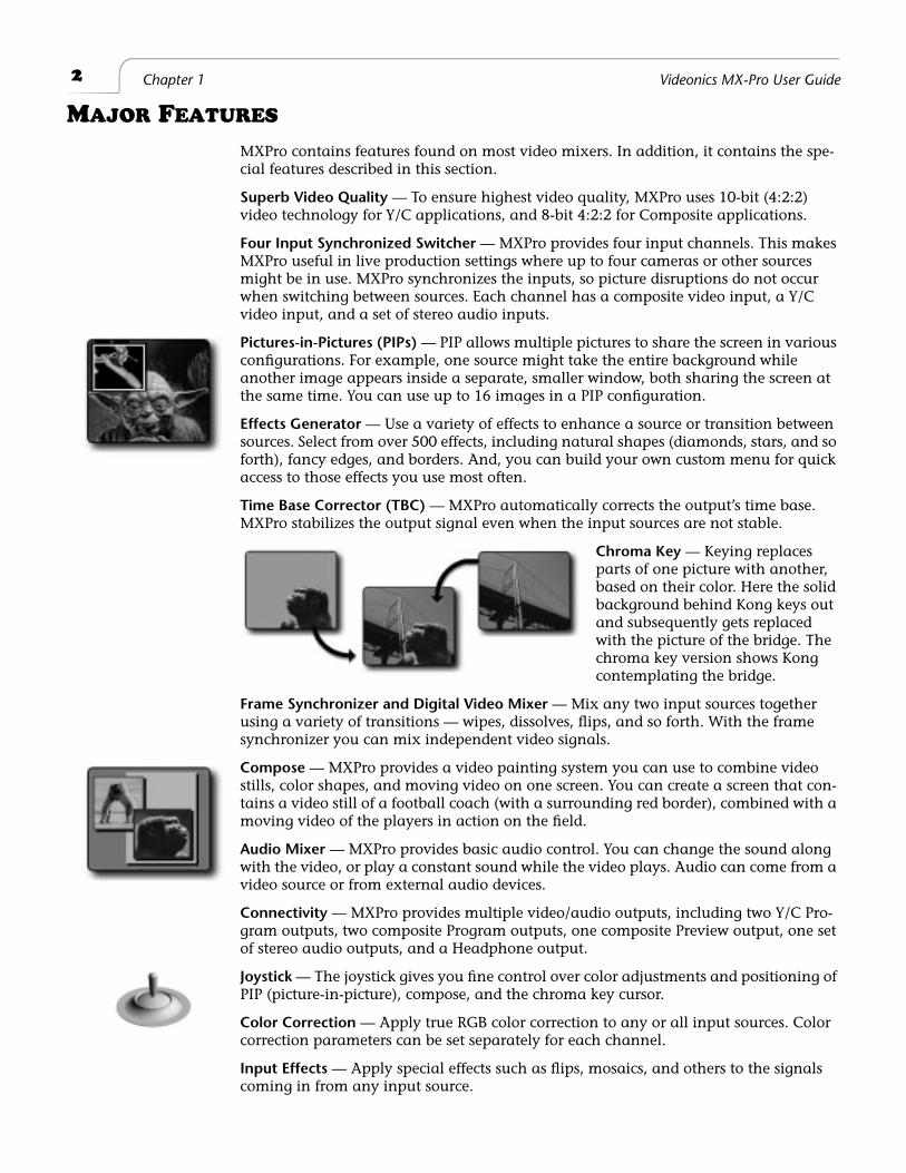
Chroma Key
— Keying replaces parts of one picture with another, based on their color. Here the solid background behind Kong keys out and subsequently gets replaced with the picture of the bridge. The chroma key version shows Kong contemplating the bridge.
Frame Synchronizer and Digital Video Mixer
— Mix any two input sources together using a variety of transitions — wipes, dissolves, flips, and so forth. With the frame synchronizer you can mix independent video signals.
Compose
— MXPro provides a video painting system you can use to combine video stills, color shapes, and moving video on one screen. You can create a screen that con-tains a video still of a football coach (with a surrounding red border), combined with a moving video of the players in action on the field.
Audio Mixer
— MXPro provides basic audio control. You can change the sound along with the video, or play a constant sound while the video plays. Audio can come from a video source or from external audio devices.
Connectivity
— MXPro provides multiple video/audio outputs, including two Y/C Pro-gram outputs, two composite Program outputs, one composite Preview output, one set of stereo audio outputs, and a Headphone output.
Joystick
— The joystick gives you fine control over color adjustments and positioning of PIP (picture-in-picture), compose, and the chroma key cursor.
Color Correction
— Apply true RGB color correction to any or all input sources. Color correction parameters can be set separately for each channel.
Input Effects
— Apply special effects such as flips, mosaics, and others to the signals coming in from any input source.
3
Introduction Common Uses for MXPro
C
OMMON
U
SES
FOR
MXP
RO
Multiple-Source Video Production
— In a video production setup, you can connect one or more video sources (VCR’s, camcorders, video disc players, cameras, title generators, computer graphics systems, and so forth) to MXPro’s four input channels. The Program output can then be sent to a VTR or directly to a monitor.
You determine what is sent to the output. While the original inputs play, you can switch between any of MXPro’s channels. You can use dissolves or other transitions to go from one channel to another. You can add special effects to any channel, and use advanced features such as compose and chroma key to enhance the production.
Single-Source Use
— MXPro supports A/A roll, a method for creating interesting transi-tions with a single source. Its digital effects (such as picture freeze, posterization, and zooms) give added life to productions. You can use MXPro with a titler to mix and superimpose titles. Time Base Correction improves the picture (especially when making multiple-generation copies) by removing the jitter common to most VCR’s.
Live Video
— In live production setups, MXPro processes events as they occur. Good coverage requires seeing the events from different vantage points—which means you need multiple input sources. MXPro gives you the ability to connect up to four sources simultaneously. For example, at a sporting event, camera one might focus on the play-ing field, camera two on the team benches, camera three on the announcer, and cam-era four on the scoreboard. Using MXPro you can easily switch between the sources whenever necessary.
Note
MXPro is
not
an edit controller — that is, it does not control VCR’s, camcorders, and similar devices. You can control the sources manually, or use external edit controllers
such as those manufactured by Videonics.
4
Chapter 1 Videonics MX-Pro User Guide
MXP
RO
P
ACKAGE
C
ONTENTS
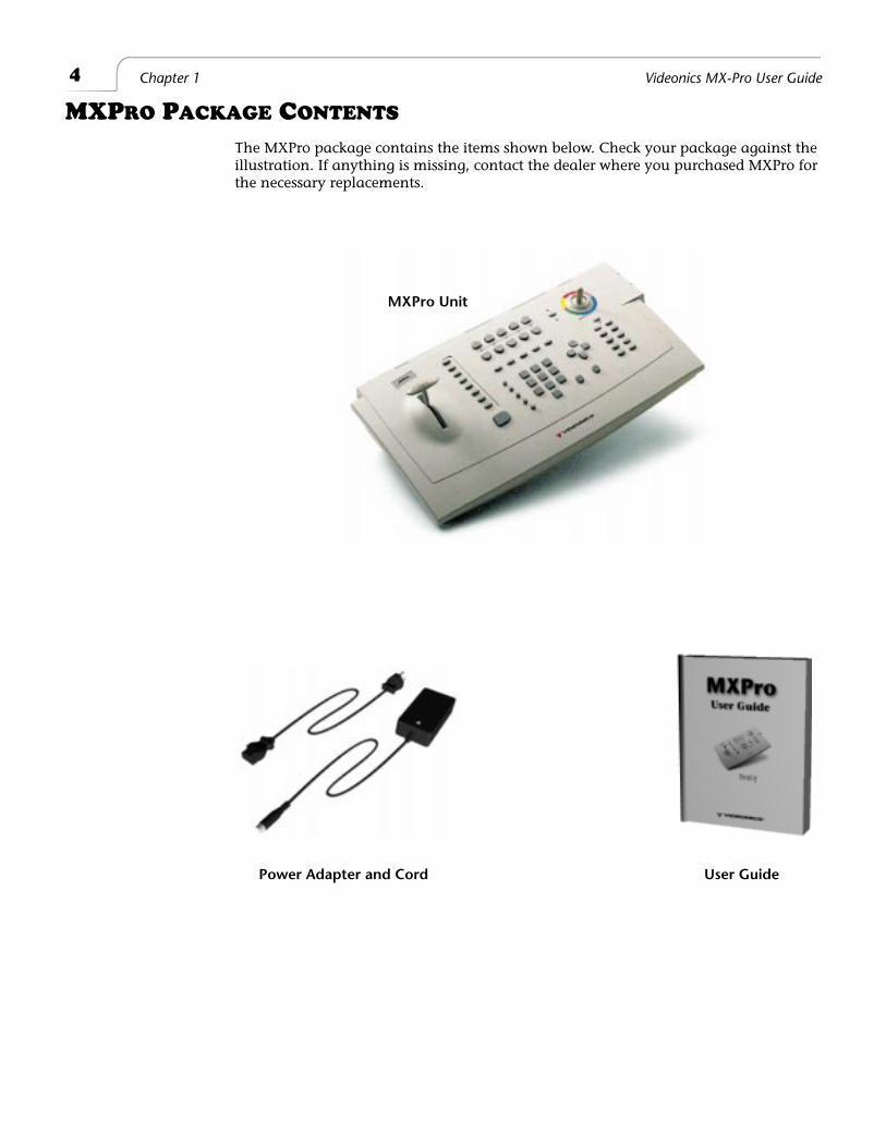
The MXPro package contains the items shown below. Check your package against the illustration. If anything is missing, contact the dealer where you purchased MXPro for the necessary replacements.
Power Adapter and Cord User Guide
MXPro Unit
5
Introduction About this User Guide
A
BOUT
THIS
U
SER
G
UIDE
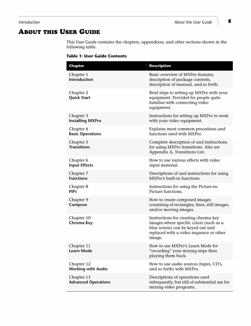
This User Guide contains the chapters, appendixes, and other sections shown in the following table.
Table 1: User Guide Contents
Chapter Description
Chapter 1
Introduction
Basic overview of MXPro features, description of package contents, description of manual, and so forth.
Chapter 2
Quick Start
Brief steps to setting up MXPro with your equipment. Provided for people quite familiar with connecting video equipment.
Chapter 3
Installing MXPro
Instructions for setting up MXPro to work with your video equipment.
Chapter 4
Basic Operations
Explains most common procedures and functions used with MXPro.
Chapter 5
Transitions
Complete description of and instructions for using MXPro transitions. Also see Appendix A, Transitions List.
Chapter 6
Input Effects
How to use various effects with video input material.
Chapter 7
Functions
Descriptions of and instructions for using MXPro’s built-in functions.
Chapter 8
PIPs
Instructions for using the Picture-in-Picture functions.
Chapter 9
Compose
How to create composed images consisting of rectangles, lines, still images, and/or moving images.
Chapter 10
Chroma Key
Instructions for creating chroma key images where specific colors (such as a blue screen) can be keyed out and replaced with a video sequence or other image.
Chapter 11
Learn Mode
How to use MXPro’s Learn Mode for “recording” your mixing steps then playing them back.
Chapter 12
Working with Audio
How to use audio sources (tapes, CD’s, and so forth) with MXPro.
Chapter 13
Advanced Operations
Descriptions of operations used infrequently, but still of substantial use for mixing video programs.
6
Chapter 1 Videonics MX-Pro User Guide
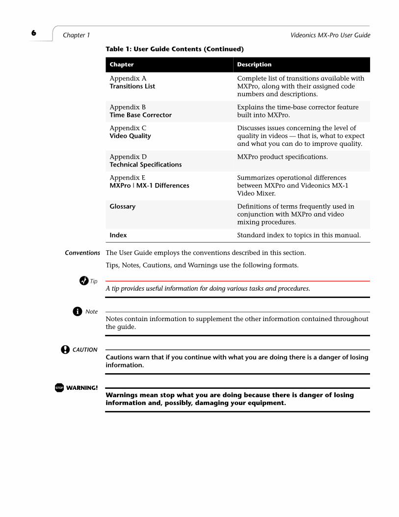
Conventions
The User Guide employs the conventions described in this section.
Tips, Notes, Cautions, and Warnings use the following formats.
Tip
A tip provides useful information for doing various tasks and procedures.
Note
Notes contain information to supplement the other information contained throughout
the guide.
CAUTION
Cautions warn that if you continue with what you are doing there is a danger of losing
information.
WARNING!
Warnings mean stop what you are doing because there is danger of losing
information and, possibly, damaging your equipment.
Appendix A
Transitions List
Complete list of transitions available with MXPro, along with their assigned code numbers and descriptions.
Appendix B
Time Base Corrector
Explains the time-base corrector feature built into MXPro.
Appendix C
Video Quality
Discusses issues concerning the level of quality in videos — that is, what to expect and what you can do to improve quality.
Appendix D
Technical Specifications
MXPro product specifications.
Appendix E
MXPro | MX-1 Differences
Summarizes operational differences between MXPro and Videonics MX-1 Video Mixer.
Glossary
Definitions of terms frequently used in conjunction with MXPro and video mixing procedures.
Index
Standard index to topics in this manual.
Table 1: User Guide Contents (Continued)
Chapter Description
7
Introduction About this User Guide
MXPro Buttons
When referencing the various buttons (or, keys) and other controls on the MXPro key-board, they appear in uppercase, boldface characters. For example, the keyboard con-
tains the
PLAY
button and
T-BAR
.
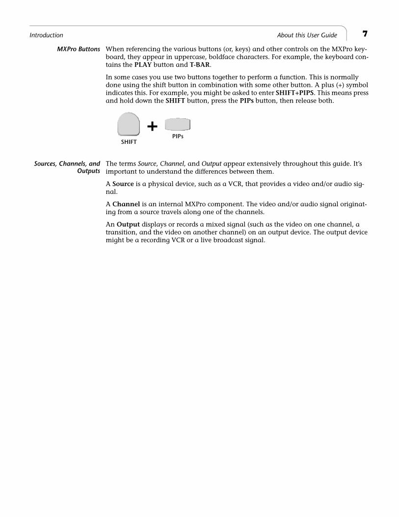
In some cases you use two buttons together to perform a function. This is normally done using the shift button in combination with some other button. A plus (+) symbol indicates this. For example, you might be asked to enter
SHIFT+PIPS
. This means press
and hold down the
SHIFT
button, press the
PIPs
button, then release both.
Sources, Channels, andOutputs
The terms
Source
,
Channel
, and
Output
appear extensively throughout this guide. It’s important to understand the differences between them.
A
Source
is a physical device, such as a VCR, that provides a video and/or audio sig-nal.
A
Channel
is an internal MXPro component. The video and/or audio signal originat-ing from a source travels along one of the channels.
An
Output displays or records a mixed signal (such as the video on one channel, a transition, and the video on another channel) on an output device. The output device might be a recording VCR or a live broadcast signal.
SHIFTPIPs
8 Chapter 1 Videonics MX-Pro User Guide
CONTACTING VIDEONICS
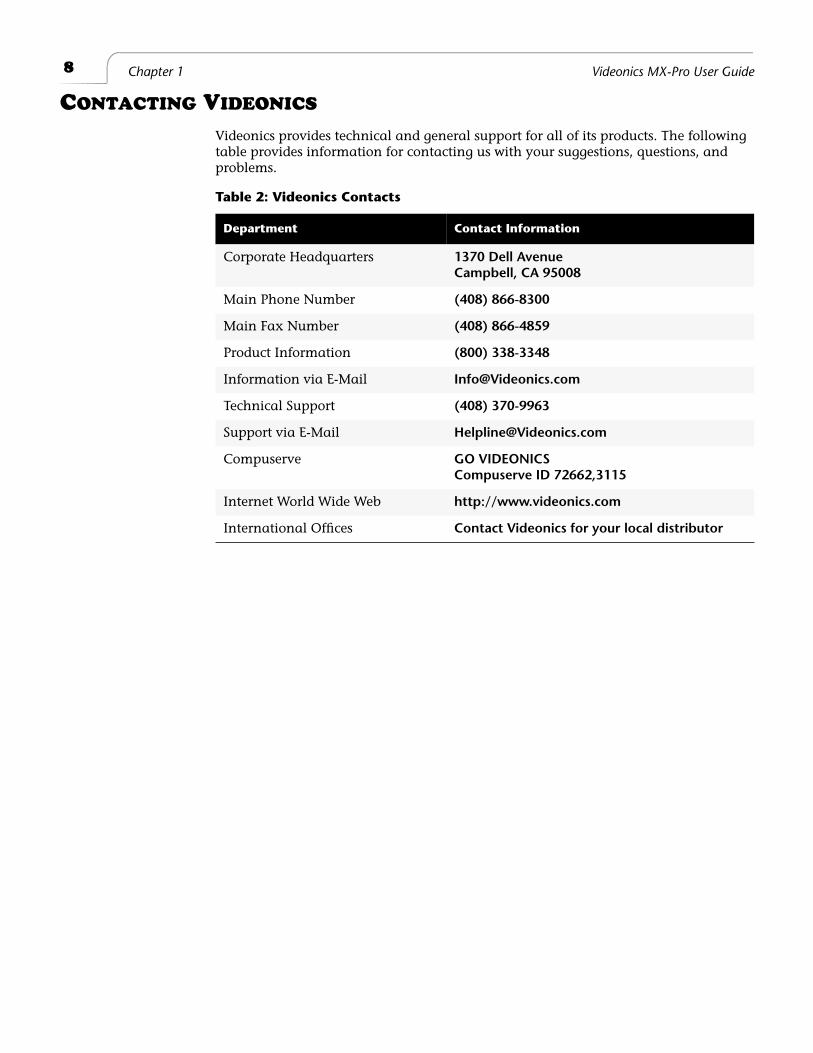
Videonics provides technical and general support for all of its products. The following table provides information for contacting us with your suggestions, questions, and problems.
Table 2: Videonics Contacts
Department Contact Information
Corporate Headquarters 1370 Dell AvenueCampbell, CA 95008
Main Phone Number (408) 866-8300
Main Fax Number (408) 866-4859
Product Information (800) 338-3348
Information via E-Mail [email protected]
Technical Support (408) 370-9963
Support via E-Mail [email protected]
Compuserve GO VIDEONICSCompuserve ID 72662,3115
Internet World Wide Web http://www.videonics.com
International Offices Contact Videonics for your local distributor
2
Quick Start
This chapter contains brief instructions for setting up MXPro with basic equipment. The instructions do not go into detail. If you feel comfortable connecting video and audio equipment, you can probably get started quickly using these instructions.
If you are upgrading from the Videonics MX-1, see Appendix E,
Information for MX-1 Users
, for helpful information in setting up your MXPro.
Skim the instructions in this chapter. If you have any questions about any of the steps, turn to Chapter 3,
Installing MXPro
, and follow the detailed instructions for setting up your equipment.
10
Chapter 2 Videonics MX-Pro User Guide
Q
UICK
S
TART
S
TEPS
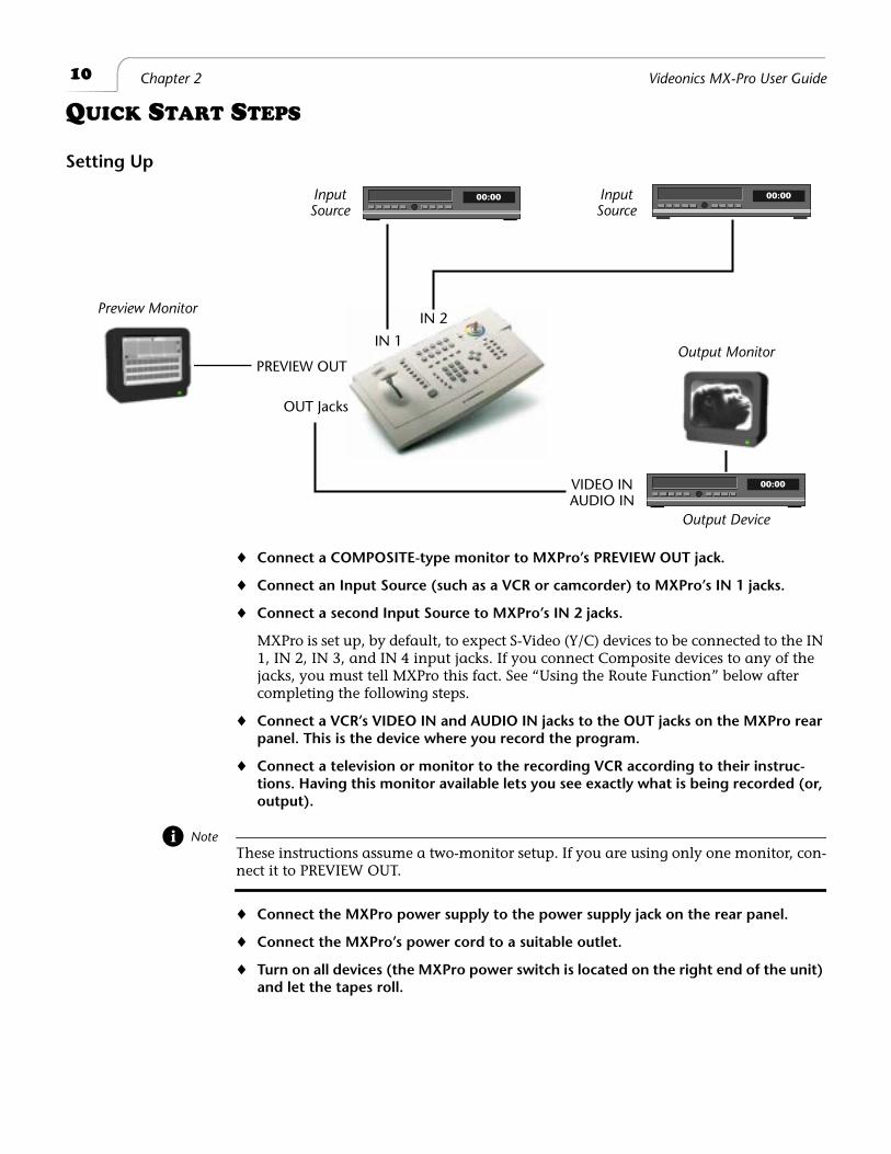
Setting Up
¨
Connect a COMPOSITE-type monitor to MXPro’s PREVIEW OUT jack.
¨
Connect an Input Source (such as a VCR or camcorder) to MXPro’s IN 1 jacks.
¨
Connect a second Input Source to MXPro’s IN 2 jacks.
MXPro is set up, by default, to expect S-Video (Y/C) devices to be connected to the IN 1, IN 2, IN 3, and IN 4 input jacks. If you connect Composite devices to any of the jacks, you must tell MXPro this fact. See “Using the Route Function” below after completing the following steps.
¨
Connect a VCR’s VIDEO IN and AUDIO IN jacks to the OUT jacks on the MXPro rear panel. This is the device where you record the program.
¨
Connect a television or monitor to the recording VCR according to their instruc-tions. Having this monitor available lets you see exactly what is being recorded (or, output).
Note
These instructions assume a two-monitor setup. If you are using only one monitor, con-
nect it to PREVIEW OUT.
¨
Connect the MXPro power supply to the power supply jack on the rear panel.
¨
Connect the MXPro’s power cord to a suitable outlet.
¨
Turn on all devices (the MXPro power switch is located on the right end of the unit) and let the tapes roll.
00:00
00:00 00:00
Preview Monitor
InputSource
InputSource
Output Device
Output MonitorPREVIEW OUT
VIDEO INAUDIO IN
OUT Jacks
IN 1
IN 2
11
Quick Start The Preview Screen
The Preview Screen
¨
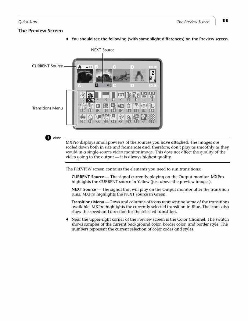
You should see the following (with some slight differences) on the Preview screen.
Note
MXPro displays small previews of the sources you have attached. The images are scaled down both in size and frame rate and, therefore, don’t play as smoothly as they would in a single-source video monitor image. This does not affect the quality of the
video going to the output — it is always highest quality.
The PREVIEW screen contains the elements you need to run transitions:
CURRENT Source
— The signal currently playing on the Output monitor. MXPro highlights the CURRENT source in Yellow (just above the preview images).
NEXT Source
— The signal that will play on the Output monitor after the transition runs. MXPro highlights the NEXT source in Green.
Transitions Menu
— Rows and columns of icons representing some of the transitions available. MXPro highlights the currently selected transition in Blue. The icons also show the speed and direction for the selected transition.
¨
Near the upper-right corner of the Preview screen is the Color Channel. The swatch shows samples of the current background color, border color, and border style. The numbers represent the current selection of color codes and styles.
CURRENT Source
NEXT Source
Transitions Menu
12
Chapter 2 Videonics MX-Pro User Guide
Using the RouteFunction
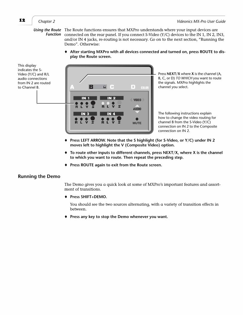
The Route functions ensures that MXPro understands where your input devices are connected on the rear panel. If you connect S-Video (Y/C) devices to the IN 1, IN 2, IN3, and/or IN 4 jacks, re-routing is not necessary. Go on to the next section, “Running the Demo”. Otherwise:
¨
After starting MXPro with all devices connected and turned on, press ROUTE to dis-play the Route screen.
¨
Press LEFT ARROW. Note that the S highlight (for S-Video, or Y/C) under IN 2 moves left to highlight the V (Composite Video) option.
¨
To route other inputs to different channels, press NEXT/X, where X is the channel to which you want to route. Then repeat the preceding step.
¨
Press ROUTE again to exit from the Route screen.
Running the Demo
The Demo gives you a quick look at some of MXPro’s important features and assort-ment of transitions.
¨
Press SHIFT+DEMO.
You should see the two sources alternating, with a variety of transition effects in between.
¨
Press any key to stop the Demo whenever you want.
MUTE
Press NEXT/X where X is the channel (A, B, C, or D) TO WHICH you want to route the signals. MXPro highlights the channel you select.
This display indicates the S-Video (Y/C) and R/L audio connections from IN 2 are routed to Channel B.
The following instructions explain how to change the video routing for channel B from the S-Video (Y/C) connection on IN 2 to the Composite connection on IN 2.
13
Quick Start Cutting Between Sources
Cutting Between Sources
¨
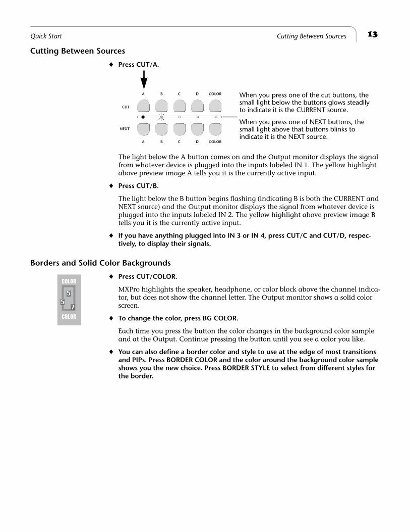
Press CUT/A.
The light below the A button comes on and the Output monitor displays the signal from whatever device is plugged into the inputs labeled IN 1. The yellow highlight above preview image A tells you it is the currently active input.
¨
Press CUT/B.
The light below the B button begins flashing (indicating B is both the CURRENT and NEXT source) and the Output monitor displays the signal from whatever device is plugged into the inputs labeled IN 2. The yellow highlight above preview image B tells you it is the currently active input.
¨
If you have anything plugged into IN 3 or IN 4, press CUT/C and CUT/D, respec-tively, to display their signals.
Borders and Solid Color Backgrounds
¨
Press CUT/COLOR.
MXPro highlights the speaker, headphone, or color block above the channel indica-tor, but does not show the channel letter. The Output monitor shows a solid color screen.
¨
To change the color, press BG COLOR.
Each time you press the button the color changes in the background color sample and at the Output. Continue pressing the button until you see a color you like.
¨
You can also define a border color and style to use at the edge of most transitions and PIPs. Press BORDER COLOR and the color around the background color sample shows you the new choice. Press BORDER STYLE to select from different styles for the border.
CUT
NEXT
A B C D COLOR
A B C D COLOR
When you press one of the cut buttons, thesmall light below the buttons glows steadilyto indicate it is the CURRENT source.
When you press one of NEXT buttons, thesmall light above that buttons blinks to indicate it is the NEXT source.
14
Chapter 2 Videonics MX-Pro User Guide
Setting up a Transition
To set up a transition you need to select the sources you want to use and the transition you want to use when switching between them. Here’s how to transition from source A to source B using a horizontal wipe.
¨
Press CUT/A to set A as the CURRENT source. MXPro shows a steadily glowing light below the CUT button you press.
¨
Press NEXT/B to set B as the NEXT source (the one you want to see after the transi-tion finishes running). The LED light above the button you press flashes to indicate it is the NEXT source.
¨
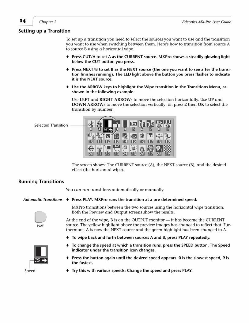
Use the ARROW keys to highlight the Wipe transition in the Transitions Menu, as shown in the following example.
Use
LEFT
and
RIGHT ARROW
s to move the selection horizontally. Use
UP
and
DOWN ARROW
s to move the selection vertically: or, press
2
then
OK
to select the transition by number.
The screen shows: The CURRENT source (A), the NEXT source (B), and the desired effect (the horizontal wipe).
Running Transitions
You can run transitions automatically or manually.
Automatic Transitions
¨
Press PLAY. MXPro runs the transition at a pre-determined speed.
MXPro transitions between the two sources using the horizontal wipe transition. Both the Preview and Output screens show the results.
At the end of the wipe, B is on the OUTPUT monitor — it has become the CURRENT source. The yellow highlight above the preview images has changed to reflect that. Fur-thermore, A is now the NEXT source and the green highlight has been changed to A.
¨
To wipe back and forth between sources A and B, press PLAY repeatedly.
¨
To change the speed at which a transition runs, press the SPEED button. The Speed indicator under the transition icon changes.
¨
Press the button again until the desired speed appears. 0 is the slowest speed, 9 is the fastest.
¨
Try this with various speeds: Change the speed and press PLAY.
Selected Transition
Speed
PLAY
15
Quick Start Using CUT Transitions
Manual Transitions
Use the
TAKE BAR
to run transitions and control their speed and direction.
¨
Set up the transition as you would normally. However, instead of pressing PLAY, simply move the T-BAR.
The transition begins running as soon as you move the
T-BAR
. You can even move back and forth by moving the
T-BAR
in different directions. Give it a try!
Using CUT Transitions
Most video productions use simple cuts a majority of the time. To cut between any two sources (for example, you could cut from A to C to COLOR to D), use the
CUT
buttons.
There’s a quick way to cut back and forth between two sources (such as A to B to A to B) using just the
PLAY
button, instead of having to alternate between two
CUT
buttons:
¨
Press 0 to select transition 0, a simple cut.
¨
Press PLAY again and again.
¨
A solid color screen can be used as if it were a separate source. Press the NEXT/COLOR button and run any transition, or press CUT/COLOR.
Choosing Transitions
The Preview screen contains the Transitions Menu. This menu contains icons and other information for all MXPro transitions. A blue highlight indicates the transition selected for the next transition.
¨
Select Transitions in the following ways:
ARROW
keys
– Simply use the arrow keys to highlight the desired transition.
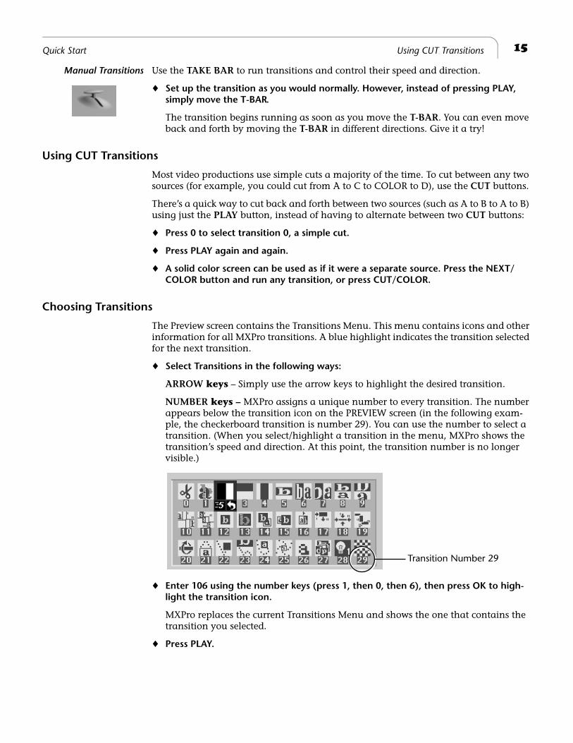
NUMBER
keys –
MXPro assigns a unique number to every transition. The number appears below the transition icon on the PREVIEW screen (in the following exam-ple, the checkerboard transition is number 29). You can use the number to select a transition. (When you select/highlight a transition in the menu, MXPro shows the transition’s speed and direction. At this point, the transition number is no longer visible.)
¨
Enter 106 using the number keys (press 1, then 0, then 6), then press OK to high-light the transition icon.
MXPro replaces the current Transitions Menu and shows the one that contains the transition you selected.
¨ Press PLAY.
Transition Number 29
16 Chapter 2 Videonics MX-Pro User Guide
Using Transition Categories
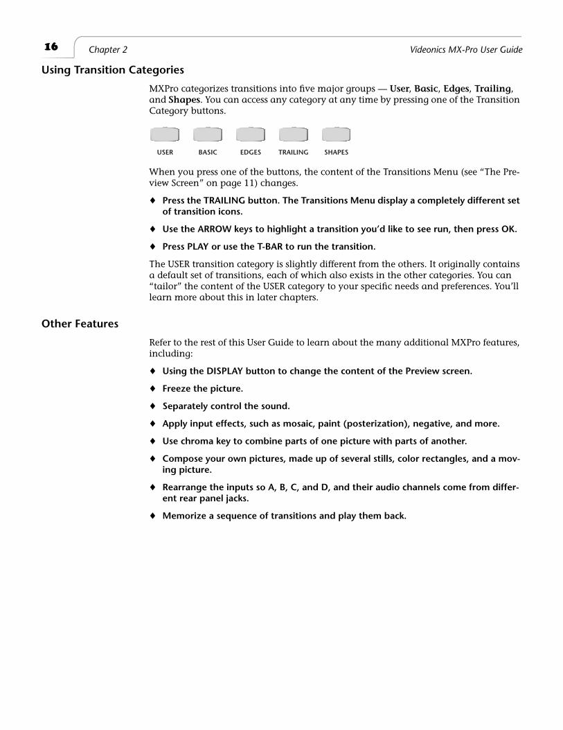
MXPro categorizes transitions into five major groups — User, Basic, Edges, Trailing, and Shapes. You can access any category at any time by pressing one of the Transition Category buttons.
When you press one of the buttons, the content of the Transitions Menu (see “The Pre-view Screen” on page 11) changes.
¨ Press the TRAILING button. The Transitions Menu display a completely different set of transition icons.
¨ Use the ARROW keys to highlight a transition you’d like to see run, then press OK.
¨ Press PLAY or use the T-BAR to run the transition.
The USER transition category is slightly different from the others. It originally contains a default set of transitions, each of which also exists in the other categories. You can “tailor” the content of the USER category to your specific needs and preferences. You’ll learn more about this in later chapters.
Other Features
Refer to the rest of this User Guide to learn about the many additional MXPro features, including:
¨ Using the DISPLAY button to change the content of the Preview screen.
¨ Freeze the picture.
¨ Separately control the sound.
¨ Apply input effects, such as mosaic, paint (posterization), negative, and more.
¨ Use chroma key to combine parts of one picture with parts of another.
¨ Compose your own pictures, made up of several stills, color rectangles, and a mov-ing picture.
¨ Rearrange the inputs so A, B, C, and D, and their audio channels come from differ-ent rear panel jacks.
¨ Memorize a sequence of transitions and play them back.
USER BASIC EDGES TRAILING SHAPES
3
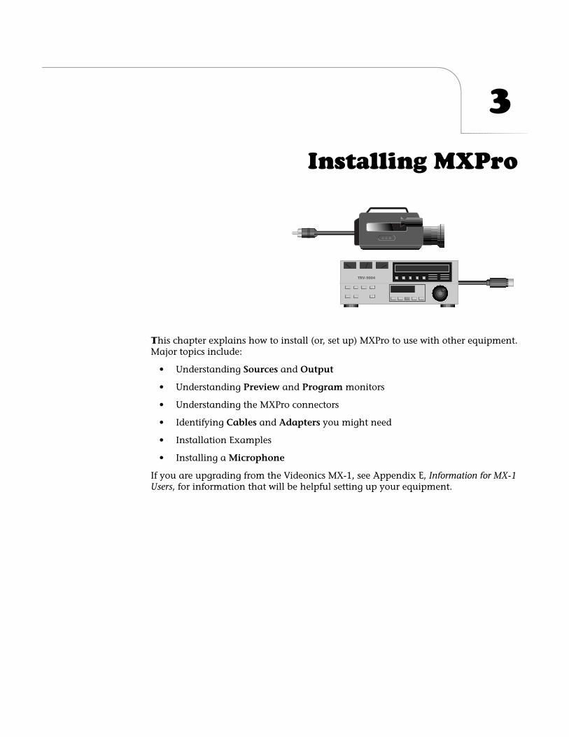
Installing MXPro
T
his chapter explains how to install (or, set up) MXPro to use with other equipment. Major topics include:
• Understanding
Sources
and
Output
• Understanding
Preview
and
Program
monitors
• Understanding the MXPro connectors
• Identifying
Cables
and
Adapters
you might need
• Installation Examples
• Installing a
Microphone
If you are upgrading from the Videonics MX-1, see Appendix E,
Information for MX-1 Users
, for information that will be helpful setting up your equipment.
18
Chapter 3 Videonics MX-Pro User Guide
S
OURCES
AND
O
UTPUT
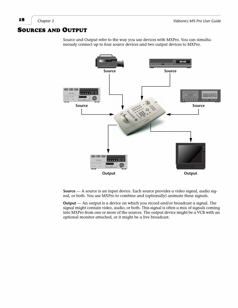
Source and Output refer to the way you use devices with MXPro. You can simulta-neously connect up to four source devices and two output devices to MXPro.
Source
— A source is an input device. Each source provides a video signal, audio sig-nal, or both. You use MXPro to combine and (optionally) animate these signals.
Output
— An output is a device on which you record and/or broadcast a signal. The signal might contain video, audio, or both. This signal is often a mix of signals coming into MXPro from one or more of the sources. The output device might be a VCR with an optional monitor attached, or it might be a live broadcast.
00:00
Source Source
Source Source
Output Output
19
Installing MXPro Preview and Program Monitors
P
REVIEW
AND
P
ROGRAM
M
ONITORS
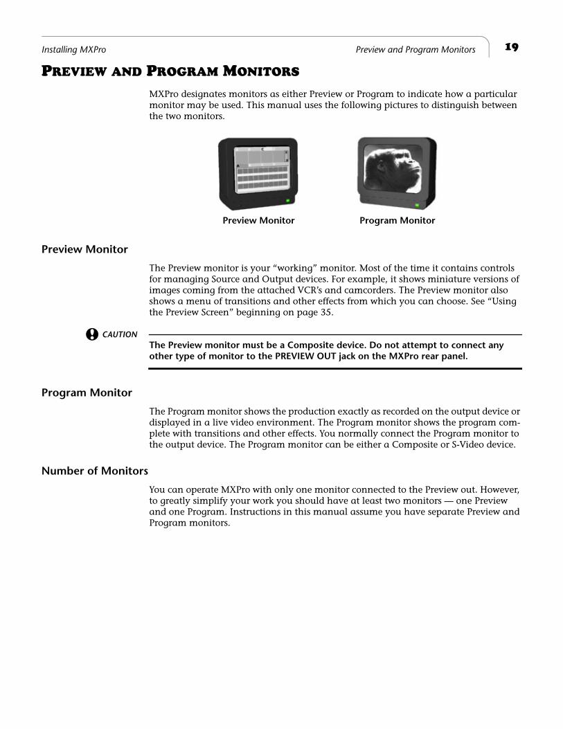
MXPro designates monitors as either Preview or Program to indicate how a particular monitor may be used. This manual uses the following pictures to distinguish between the two monitors.
Preview Monitor
The Preview monitor is your “working” monitor. Most of the time it contains controls for managing Source and Output devices. For example, it shows miniature versions of images coming from the attached VCR’s and camcorders. The Preview monitor also shows a menu of transitions and other effects from which you can choose. See “Using the Preview Screen” beginning on page 35.
CAUTION
The Preview monitor must be a Composite device. Do not attempt to connect any
other type of monitor to the PREVIEW OUT jack on the MXPro rear panel.
Program Monitor
The Program monitor shows the production exactly as recorded on the output device or displayed in a live video environment. The Program monitor shows the program com-plete with transitions and other effects. You normally connect the Program monitor to the output device. The Program monitor can be either a Composite or S-Video device.
Number of Monitors
You can operate MXPro with only one monitor connected to the Preview out. However, to greatly simplify your work you should have at least two monitors — one Preview and one Program. Instructions in this manual assume you have separate Preview and Program monitors.
Preview Monitor Program Monitor
20
Chapter 3 Videonics MX-Pro User Guide
U
NDERSTANDING
MXP
RO
C
ONNECTORS
To properly set up MXPro, you need to know how and where to connect external com-ponents – such as VCR’s, camcorders, and so forth. You use cables to connect video devices to MXPro’s rear panel. See “Cables and Adapters” on page 23.
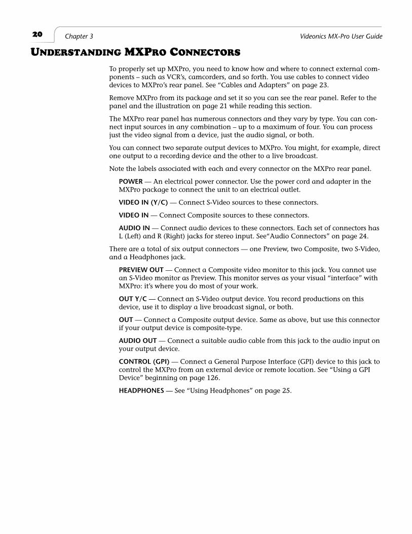
Remove MXPro from its package and set it so you can see the rear panel. Refer to the panel and the illustration on page 21 while reading this section.
The MXPro rear panel has numerous connectors and they vary by type. You can con-nect input sources in any combination – up to a maximum of four. You can process just the video signal from a device, just the audio signal, or both.
You can connect two separate output devices to MXPro. You might, for example, direct one output to a recording device and the other to a live broadcast.
Note the labels associated with each and every connector on the MXPro rear panel.
POWER
— An electrical power connector. Use the power cord and adapter in the MXPro package to connect the unit to an electrical outlet.
VIDEO IN (Y/C)
— Connect S-Video sources to these connectors.
VIDEO IN
— Connect Composite sources to these connectors.
AUDIO IN
— Connect audio devices to these connectors. Each set of connectors has L (Left) and R (Right) jacks for stereo input. See“Audio Connectors” on page 24.
There are a total of six output connectors — one Preview, two Composite, two S-Video, and a Headphones jack.
PREVIEW OUT
— Connect a Composite video monitor to this jack. You cannot use an S-Video monitor as Preview. This monitor serves as your visual “interface” with MXPro: it’s where you do most of your work.
OUT Y/C
— Connect an S-Video output device. You record productions on this device, use it to display a live broadcast signal, or both.
OUT
— Connect a Composite output device. Same as above, but use this connector if your output device is composite-type.
AUDIO OUT
— Connect a suitable audio cable from this jack to the audio input on your output device.
CONTROL (GPI)
— Connect a General Purpose Interface (GPI) device to this jack to control the MXPro from an external device or remote location. See “Using a GPI Device” beginning on page 126.
HEADPHONES
— See “Using Headphones” on page 25.
21
Installing MX
ProU
nderstanding MX
Pro Connectors
VIDEOIN (Y/C)
OUT(Y/C)
OUT AUDIO OUT CONTROL(GPI)
VIDEOIN
POWER
AUDIOIN
PREVIEW OUTDIGITAL VIDEO IN(FUTURE
UPGRADE)
1 2
1 23 4
1
L
R
L
R
L
R
L
R
2 3 43 4
MXPro Rear Panel
POWER OUT Y/CS-Video
AUDIO OUTLeft and Right
VIDEO IN (Y/C)S-Video
VIDEO IN Composite
AUDIO IN Left and Right
PREVIEW OUTComposite
OUTComposite
CONTROL (GPI)
22
Chapter 3 Videonics MX-Pro User Guide
Power Connector
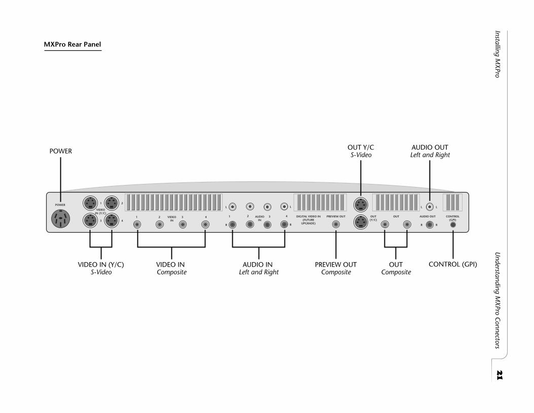
The MXPro package contains the required Transformer and Power Cord for the unit.
WARNING!
Use only the power cord and transformer provided in the package. Do not use this power cord and transformer with any other equipment. Failure to observe
these conditions can damage your equipment and void your warranty.
Procedure
To connect the power cord and transformer:
1
Connect the Female Plug on the Power Cord into the Male Socket on the Trans-former.
2
Connect the Male Plug on the Power Cord to a suitable power outlet.
3
Connect the Power Adapter Plug on the Transformer cord into the Power connec-tor on the MXPro rear panel.
4
Turn the MXPro Power Switch (located on the right side of the unit) to the ON position.
PowerAdapter
Plug
MalePlug
Male Socket Female Plug
Transformer Power Cord
23
Installing MXPro Cables and Adapters
C
ABLES
AND
A
DAPTERS
To connect video devices to MXPro you need specific types of cables. You might also need one or more adapters, depending on your equipment.
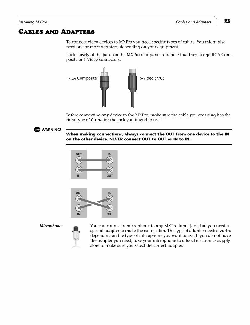
Look closely at the jacks on the MXPro rear panel and note that they accept RCA Com-posite or S-Video connectors.
Before connecting any device to the MXPro, make sure the cable you are using has the right type of fitting for the jack you intend to use.
WARNING!
When making connections, always connect the OUT from one device to the IN
on the other device. NEVER connect OUT to OUT or IN to IN.
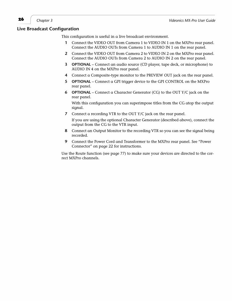
Microphones
You can connect a microphone to any MXPro input jack, but you need a special adapter to make the connection. The type of adapter needed varies depending on the type of microphone you want to use. If you do not have the adapter you need, take your microphone to a local electronics supply store to make sure you select the correct adapter.
RCA Composite S-Video (Y/C)
OUT
IN
IN
OUT
OUT
IN
IN
OUT
24
Chapter 3 Videonics MX-Pro User Guide
Audio Connectors
To connect a stereophonic audio device to MXPro, you need two separate audio cables — one for the Left channel and one for the Right.
To connect a monaural audio device you need a Y-Adapter cable. Connect the single end of the adapter to the line input or output on the device. Connect the two remaining ends to the Left and Right channel inputs or outputs on the MXPro rear panel.
The Y-Adapter cable does not provide stereophonic audio. It simply directs the mono signal to or from both MXPro channels.
You can also connect a mono audio device using a single cable. Con-nect one end to the line in or out on the audio device, then connect the other end to either the Left or Right MXPro channel connector using the IN 3 set of inputs (only IN 3 can be configured for mono). Once connected, use the MXPro ROUTE function to specify which con-nector (Left or Right) you used. See “Route” beginning on page 77.
I
NSTALLATION
E
XAMPLES
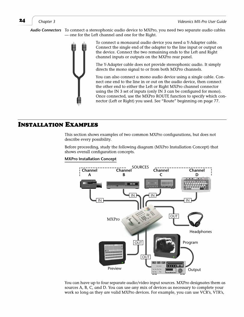
This section shows examples of two common MXPro configurations, but does not describe every possibility.
Before proceeding, study the following diagram (MXPro Installation Concept) that shows overall configuration concepts.
You can have up to four separate audio/video input sources. MXPro designates them as sources A, B, C, and D. You can use any mix of devices as necessary to complete your work so long as they are valid MXPro devices. For example, you can use VCR’s, VTR’s,
00:00
POWERDEMO
tab
newline OK
deleteundo
posn
pageup
pagedown
capslock
shift shift
cmd PLAY PLAYaccent
FONT &SIZE STYLE COLOR PATTERN COLOR PATTERN COLOR STYLE COLOR PATTERN IN OUT copy move mark
start
pageindex
newpage
markend
1 2 3 4 5 6 7 8 9 0 - =
Q W E R T Y U I O P [ ] \
A S D F G H J K L ; '
Z X C V B N M , . /12
!!
@ # $ % ^ & * ( ) _ +
{ }
:
< > ??
"
FONT LETTER OUTLINE BORDERS BACKGROUND EFFECTS
X
^~ " v 0
{ } |¢ £ ¥ ® • Œ « »©™
Æ ‘ ’ß
Ç “ ”
§ Ö� H u n©�
HEADPHONES
ININ IN
IN
OUT
OUT
OUT
MXPro Installation Concept
SOURCESChannel
AChannel
BChannel
CChannel
D
MXPro
Headphones
Preview Output
Program
25
Installing MXPro Correlating Input Sources to MXPro Jacks
camcorders, laserdisc players, satellite tuners, broadcast tuners/receivers, character generators (CG’s), video-equipped computers, and audio devices (such as a CD player or tape deck).
MXPro sends the output signal to a recording device (such as a VCR) and/or a Program monitor.
A second monitor, Preview, can be used to display preview images of all input sources. The Preview monitor also displays the on-screen controls you use to operate MXPro.
Correlating Input Sources to MXPro Jacks
As stated above, MXPro designates your input sources as A, B, C, and D. However, if you examine the jacks on the MXPro rear panel you’ll see they are labeled 1, 2, 3, and 4. Initially, there is a direct correlation between the letter and number designations: jack 1 corresponds to source A, jack 2 corresponds to source B, jack 3 to source C, and jack 4 to source D. You can re-route inputs to other channels. For more information, see “Route” beginning on page 77.
Using Headphones
To use headphones, connect them to the Headphone jack, which is located on the right end of the unit, near the power switch. The jack accepts standard stereo headphones with a miniature plug — however, output is monaural (a mix of right and left chan-nels), not stereo. If your headphones have a large plug, you need an adapter to switch it to a miniature plug.
VCR Selector Switches
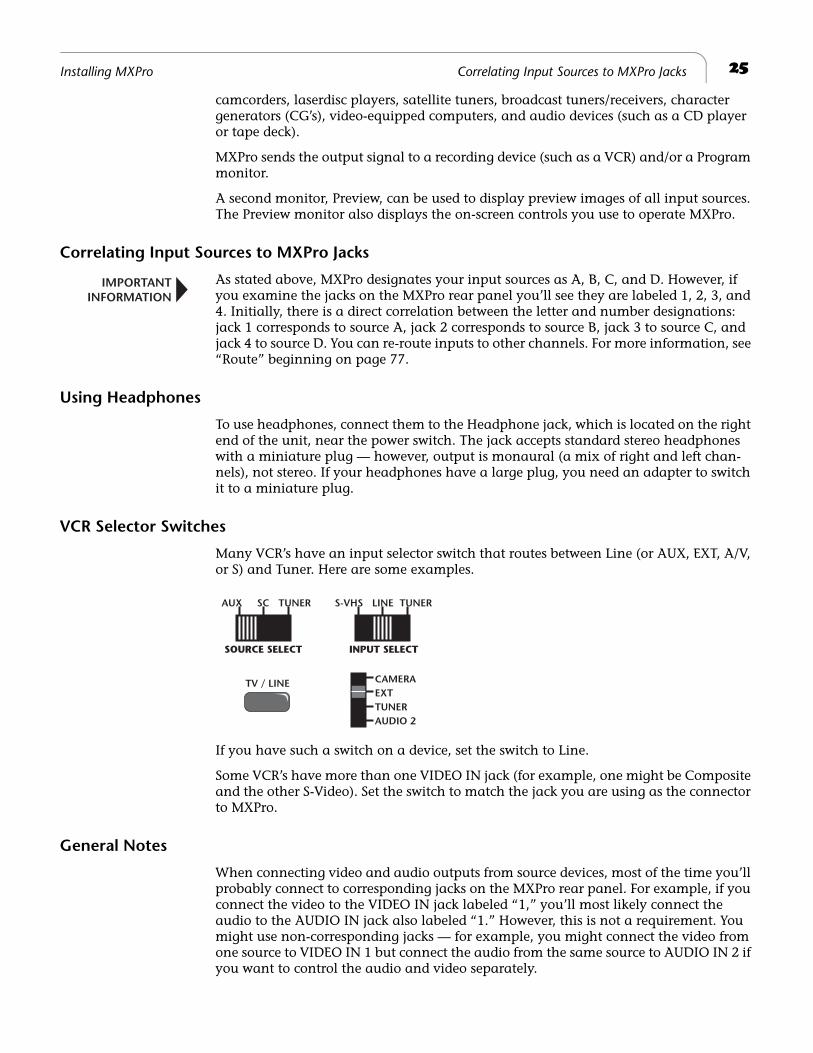
Many VCR’s have an input selector switch that routes between Line (or AUX, EXT, A/V, or S) and Tuner. Here are some examples.
If you have such a switch on a device, set the switch to Line.
Some VCR’s have more than one VIDEO IN jack (for example, one might be Composite and the other S-Video). Set the switch to match the jack you are using as the connector to MXPro.
General Notes
When connecting video and audio outputs from source devices, most of the time you’ll probably connect to corresponding jacks on the MXPro rear panel. For example, if you connect the video to the VIDEO IN jack labeled “1,” you’ll most likely connect the audio to the AUDIO IN jack also labeled “1.” However, this is not a requirement. You might use non-corresponding jacks — for example, you might connect the video from one source to VIDEO IN 1 but connect the audio from the same source to AUDIO IN 2 if you want to control the audio and video separately.
IMPORTANTINFORMATION
CAMERAEXTTUNERAUDIO 2
TV / LINE
S-VHS TUNER
INPUT SELECT
LINEAUX TUNERSC
SOURCE SELECT
26 Chapter 3 Videonics MX-Pro User Guide
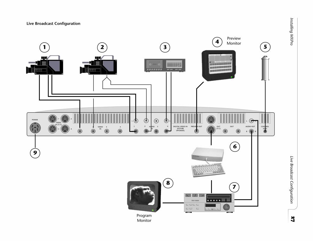
Live Broadcast Configuration
This configuration is useful in a live broadcast environment.
1 Connect the VIDEO OUT from Camera 1 to VIDEO IN 1 on the MXPro rear panel. Connect the AUDIO OUTs from Camera 1 to AUDIO IN 1 on the rear panel.
2 Connect the VIDEO OUT from Camera 2 to VIDEO IN 2 on the MXPro rear panel. Connect the AUDIO OUTs from Camera 2 to AUDIO IN 2 on the rear panel.
3 OPTIONAL – Connect an audio source (CD player, tape deck, or microphone) to AUDIO IN 4 on the MXPro rear panel.
4 Connect a Composite-type monitor to the PREVIEW OUT jack on the rear panel.
5 OPTIONAL – Connect a GPI trigger device to the GPI CONTROL on the MXPro rear panel.
6 OPTIONAL – Connect a Character Generator (CG) to the OUT Y/C jack on the rear panel.
With this configuration you can superimpose titles from the CG atop the output signal.
7 Connect a recording VTR to the OUT Y/C jack on the rear panel.
If you are using the optional Character Generator (described above), connect the output from the CG to the VTR input.
8 Connect an Output Monitor to the recording VTR so you can see the signal being recorded.
9 Connect the Power Cord and Transformer to the MXPro rear panel. See “Power Connector” on page 22 for instructions.
Use the Route function (see page 77) to make sure your devices are directed to the cor-rect MXPro channels.
27
Installing MX
ProLive Broadcast C
onfiguration
VIDEOIN (Y/C)
OUT(Y/C)
OUT AUDIO OUT CONTROL(GPI)
VIDEOIN
POWER
AUDIOIN
PREVIEW OUTDIGITAL VIDEO IN(FUTURE
UPGRADE)
1 2
1 23 4
1
L
R
L
R
L
R
L
R
2 3 43 4
Live Broadcast Configuration
1 2 34
78
5
9
ProgramMonitor
PreviewMonitor
6
28 Chapter 3 Videonics MX-Pro User Guide
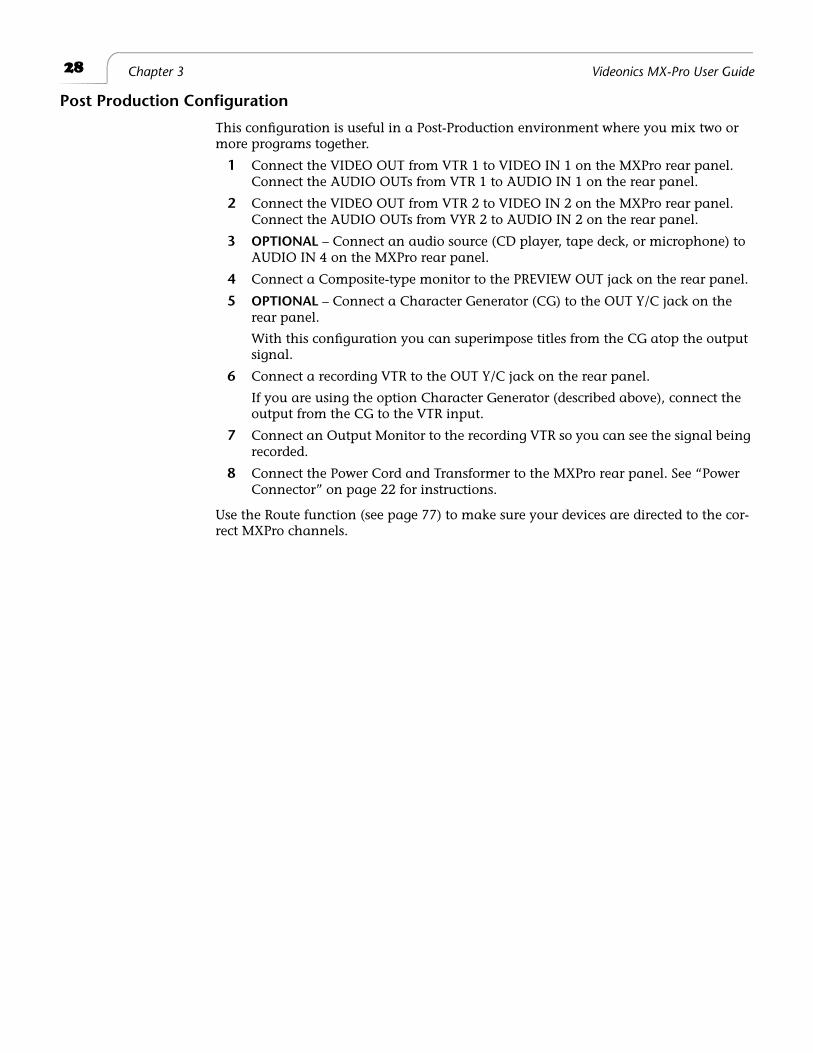
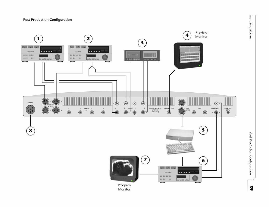
Post Production Configuration
This configuration is useful in a Post-Production environment where you mix two or more programs together.
1 Connect the VIDEO OUT from VTR 1 to VIDEO IN 1 on the MXPro rear panel. Connect the AUDIO OUTs from VTR 1 to AUDIO IN 1 on the rear panel.
2 Connect the VIDEO OUT from VTR 2 to VIDEO IN 2 on the MXPro rear panel. Connect the AUDIO OUTs from VYR 2 to AUDIO IN 2 on the rear panel.
3 OPTIONAL – Connect an audio source (CD player, tape deck, or microphone) to AUDIO IN 4 on the MXPro rear panel.
4 Connect a Composite-type monitor to the PREVIEW OUT jack on the rear panel.
5 OPTIONAL – Connect a Character Generator (CG) to the OUT Y/C jack on the rear panel.
With this configuration you can superimpose titles from the CG atop the output signal.
6 Connect a recording VTR to the OUT Y/C jack on the rear panel.
If you are using the option Character Generator (described above), connect the output from the CG to the VTR input.
7 Connect an Output Monitor to the recording VTR so you can see the signal being recorded.
8 Connect the Power Cord and Transformer to the MXPro rear panel. See “Power Connector” on page 22 for instructions.
Use the Route function (see page 77) to make sure your devices are directed to the cor-rect MXPro channels.
29
Installing MX
ProPost Production C
onfiguration
VIDEOIN (Y/C)
OUT(Y/C)
OUT AUDIO OUT CONTROL(GPI)
VIDEOIN
POWER
AUDIOIN
PREVIEW OUTDIGITAL VIDEO IN(FUTURE
UPGRADE)
1 2
1 23 4
1
L
R
L
R
L
R
L
R
2 3 43 4
Post Production Configuration
1 23
4
67
8
ProgramMonitor
PreviewMonitor
5
30 Chapter 3 Videonics MX-Pro User Guide
USING A MICROPHONE WITH MXPRO
This section explains how to connect a microphone to MXPro.
You need the following equipment:
• Professional quality microphone
• Microphone cable (male-XLR to female-XLR connectors)
• An audio Direct Box (which you can purchase from any professional audio equipment dealer)
• A 1/4 inch (Phone Jack) to RCA cable
• A female RCA to dual-male RCA “Y” Adapter
Procedure
To connect a microphone:
1 Using the microphone cable, connect it to the XLR (balanced) input on the Direct Box.
2 Plug the 1/4-inch-to-RCA cable into the 1/4-inch (unbalanced) output on the Direct Box.
3 Attach the RCA “Y” adapter to the 1/4-inch-to-RCA cable.
4 Plug the two male ends of the RCA “Y” Adapter into the Channel 4 R and L audio inputs on the MXPro rear panel.
To control the volume of the microphone, use the Background Music slider on the Audio Mixer screen (see “Using the Audio Mixer” beginning on page 118).
4
Basic Operations
T
his chapter describes several basic MXPro operations, including:
• Starting and stopping MXPro
• Using the MXPro keyboard
• Using the Preview screen
• Using CURRENT and NEXT sources
• Selecting Sources
• Using the VIDEO/AUDIO selector
• Cutting Between Sources
• Working with Color
• Using Backgrounds
• Using Borders
32
Chapter 4 Videonics MX-Pro User Guide
S
TARTING
AND
S
TOPPING
MXP
RO
Press the Power switch to start or stop MXPro. The switch, located on the right-end of the unit, is a rocker-type switch. Also power on or off all sources and output devices.
U
NDERSTANDING
THE
K
EYBOARD
Use the MXPro keyboard to control how the unit operates. The better you understand all of the functions available from the keyboard the better your results.
This section briefly describes the button groups and, in some cases, individual buttons and controls. Additional information appears throughout this User Guide. Some of the following descriptions provide a reference to the page where you can find details. Refer to the illustration on the next page while reading this material.
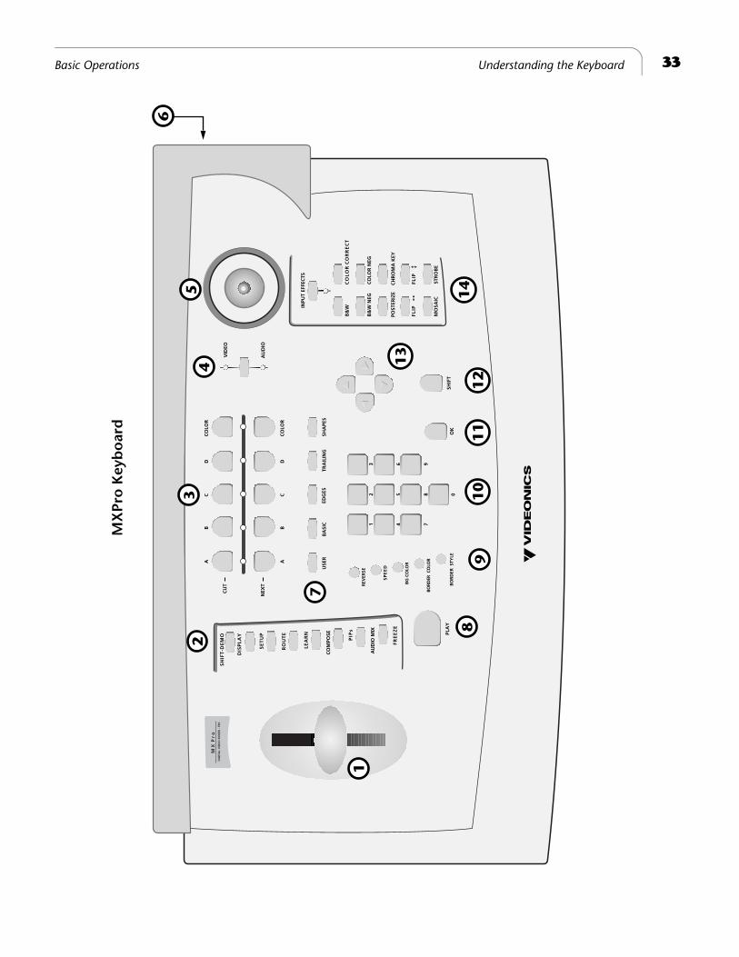
1
T-Bar (or, Take Bar)
— Use to manually control the way transitions run. See
Chapter 5,
Transitions
.
2
Function Buttons
— Provide immediate access to built-in functions, including
DISPLAY
,
SETUP
,
ROUTE
,
LEARN
,
COMPOSE
,
PIPS
,
AUDIO MIX
, and
FREEZE
. You can also access the built-in demo using these buttons. See Chapter 7,
Func-tions
, for details.
3
Source Selectors
— Use to select the CURRENT (CUT) and NEXT sources for a pro-duction. Normally, you select the CURRENT and NEXT sources, select a transition to use between the two, then run it. For example, you might select a camcorder as one input source (CURRENT) and a VCR as the other (NEXT). You then select a transition, such as a dissolve or wipe. When you reach the point in the CURRENT source where you want to change to the NEXT source, press
PLAY
or use the
T-BAR
to instruct MXPro to play the transition. The CURRENT source becomes the new NEXT source, and the old NEXT source becomes the new CURRENT source. (See “Using CURRENT and NEXT Sources” beginning on page 38.) Use the COLOR buttons to create solid colored backgrounds and other effects. (See “Working with Colors” beginning on page 42.)
4
Video/Audio Selector
— Determines whether VIDEO, AUDIO, or both VIDEO and AUDIO are affected when you run a transition. When set to
VIDEO
, the video changes but the audio does not. When set to
AUDIO
, the audio changes but the video does not. When set to both, the video and audio both change. See “Using the Video/Audio Selector” on page 40.
5
Joystick
— Provides an easy way to make fine adjustments to various compo-nents. For example, when using PIPs the joystick positions the various picture ele-ments on the screen — when using color correction, use the joystick to adjust the color. The joystick has other uses you’ll learn about in later chapters.
6
Power Switch and Headphone Jack
— These two components are located on the right-hand side of the unit, not on the top. The Power Switch is a rocker-type switch for turning the unit on and off. The Headphone Jack provides a means for connecting a set of headphones to the unit.
7
Transition Category Buttons
— Gives you immediate access to the five, major categories of transitions, including
USER
,
BASIC
,
EDGES
,
TRAILING
, and
SHAPES
. All MXPro transitions fall into one of these categories. After pressing a button, you can search through the transitions in that category to find the one you want to use. See “Transition Categories and Menus” beginning on page 52.
33
Basic Operations Understanding the Keyboard
AU
DIO
VID
EO
SHIF
TO
K
B&
W
CO
LOR
NEG
INPU
T EF
FEC
TS
MO
SAIC
FLIP
B&
W N
EG
FLIP
SP
EE
D
R
EVER
SE
BORD
ER C
OLO
R
PLA
Y
BG
CO
LOR
NEX
T
CU
T
EDG
ESU
SER
BA
SIC
TRA
ILIN
GSH
APE
S
CO
LOR
DC
BA
CO
LOR
DC
BA
0
12
3
45
6
78
9
MX
Pr
o D
IGIT
AL
VID
EO M
IXER
- T
BC
CO
MPO
SE
LE
AR
N
D
ISP
LAY
FR
EE
ZE
AU
DIO
MIX
PIP
s
S
ET
UP
RO
UT
E
S
HIF
T-D
EM
O
BO
RD
ER S
TYLE
CH
RO
MA
KEY
CO
LOR
CO
RR
EC
T
POST
ERIZ
E
STR
OB
E
1
23
45
6
8
7
910
11
14
12
13
MX
Pro
Key
bo
ard
34
Chapter 4 Videonics MX-Pro User Guide
8
Play Button
— Press to invoke the next command, complete with transition if specified. In other words, set up your CURRENT and NEXT sources, select a transi-tion, then press
PLAY
at the moment you want MXPro to perform the step.
9
Control Buttons
— Use these buttons to reverse transition direction, change tran-sition speed, specify background and border colors, and set border styles.
10
Numeric Keypad
— Use for various functions, such as entering the number of a transition you want to use, setting a precise speed for a transition, and so forth.
11
OK Button
— Generally used to indicate to MXPro that you have completed some operation and want the unit to prepare for or perform it accordingly.
12
SHIFT Button
— A modifier key that invokes special functions when used in con-junction with other keyboard keys.
13
Arrow Keys
— Primarily used for selecting effects and functions. For example, use the arrow keys to highlight a transition you want to use in the Transitions Menu.
14
INPUT EFFECTS Buttons
— Provides access to effects you can apply to input sources. The light below the
INPUT EFFECTS
button glows when MXPro is in Input Effects mode. See Chapter 6,
Input Effects
, for more information.
35
Basic Operations Using the Preview Screen
U
SING
THE
P
REVIEW
S
CREEN
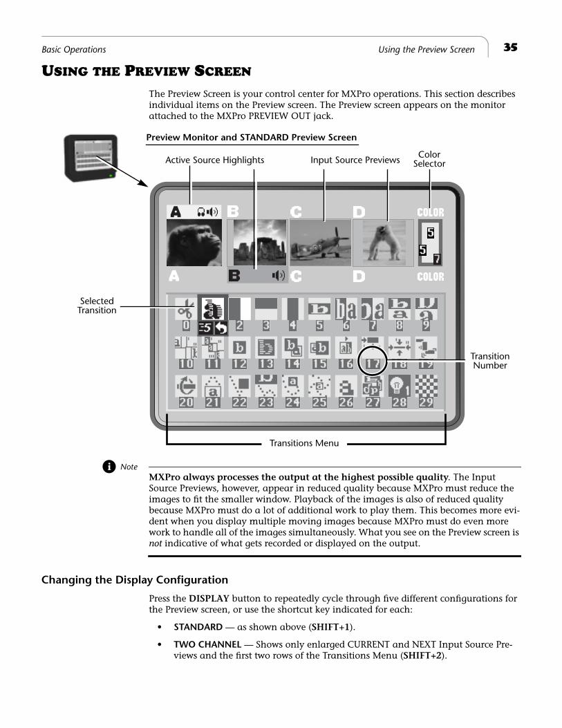
The Preview Screen is your control center for MXPro operations. This section describes individual items on the Preview screen. The Preview screen appears on the monitor attached to the MXPro PREVIEW OUT jack.
Note
MXPro always processes the output at the highest possible quality
. The Input Source Previews, however, appear in reduced quality because MXPro must reduce the images to fit the smaller window. Playback of the images is also of reduced quality because MXPro must do a lot of additional work to play them. This becomes more evi-dent when you display multiple moving images because MXPro must do even more work to handle all of the images simultaneously. What you see on the Preview screen is
not
indicative of what gets recorded or displayed on the output.
Changing the Display Configuration
Press the
DISPLAY
button to repeatedly cycle through five different configurations for the Preview screen, or use the shortcut key indicated for each:
•
STANDARD
— as shown above (
SHIFT+1
).
•
TWO CHANNEL
— Shows only enlarged CURRENT and NEXT Input Source Pre-views and the first two rows of the Transitions Menu (
SHIFT+2
).
Preview Monitor and STANDARD Preview Screen
Input Source PreviewsActive Source HighlightsColor
SelectedTransition
Transitions Menu
Selector
TransitionNumber
36
Chapter 4 Videonics MX-Pro User Guide
•
FULL
– Displays only the Input Source Preview windows, each in a larger size. Transitions Menu not displayed (
SHIFT+3
).
•
NEXT
— Displays full-screen image of the NEXT input source. Transitions Menu not displayed (
SHIFT+4
).
•
CURRENT
— Displays full-screen image of the CURRENT input source. Transitions Menu not displayed (
SHIFT+5
).
See “Display” beginning on page 73 for examples of these configurations. Unless stated otherwise, this guide assumes you are using the
STANDARD
preview.
Input Source Previews
A small, preview image from each input source appears in a separate window. Use the previews to direct the action, position cameras, find a particular sequence on a video tape, and so forth. The preview images do
not
show Input Effects (see Chapter 6,
Input Effects
).
Active Source Highlights
You can have up to four input sources. MXPro labels the sources A, B, C, and D. (There is also a fifth, built-in source — the mixer’s own background color generator.) All tran-sitions start with one source, called the CURRENT source, and end with another, called the NEXT source.
Colored highlights help identify one video source from another. Yellow highlights the CURRENT video source (above the preview image), and green highlights the NEXT video source (below it)
Some sources provide audio only, others provide both video and audio. The speaker icon (rather than a colored highlight) indicates the CURRENT and NEXT audio selections.
The headphones icon identifies the channel to which the headphone output is currently directed.
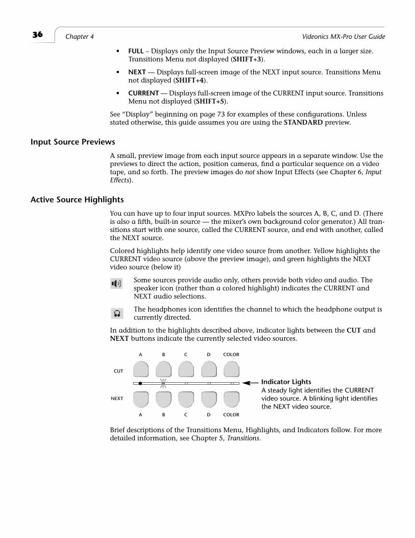
In addition to the highlights described above, indicator lights between the CUT and NEXT buttons indicate the currently selected video sources.
Brief descriptions of the Transitions Menu, Highlights, and Indicators follow. For more detailed information, see Chapter 5, Transitions.
CUT
NEXT
A B C D COLOR
A B C D COLOR
Indicator LightsA steady light identifies the CURRENT video source. A blinking light identifies the NEXT video source.
37Basic Operations Color Selector
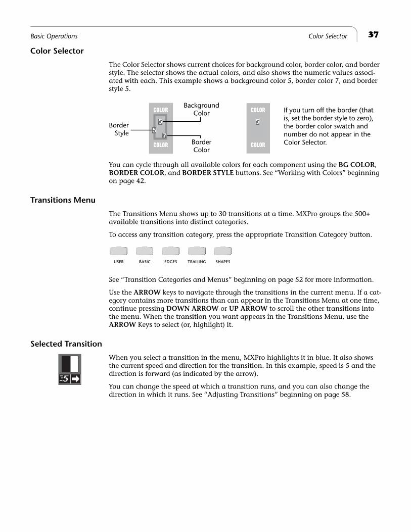
Color Selector
The Color Selector shows current choices for background color, border color, and border style. The selector shows the actual colors, and also shows the numeric values associ-ated with each. This example shows a background color 5, border color 7, and border style 5.
You can cycle through all available colors for each component using the BG COLOR, BORDER COLOR, and BORDER STYLE buttons. See “Working with Colors” beginning on page 42.
Transitions Menu
The Transitions Menu shows up to 30 transitions at a time. MXPro groups the 500+ available transitions into distinct categories.
To access any transition category, press the appropriate Transition Category button.
See “Transition Categories and Menus” beginning on page 52 for more information.
Use the ARROW keys to navigate through the transitions in the current menu. If a cat-egory contains more transitions than can appear in the Transitions Menu at one time, continue pressing DOWN ARROW or UP ARROW to scroll the other transitions into the menu. When the transition you want appears in the Transitions Menu, use the ARROW Keys to select (or, highlight) it.
Selected Transition
When you select a transition in the menu, MXPro highlights it in blue. It also shows the current speed and direction for the transition. In this example, speed is 5 and the direction is forward (as indicated by the arrow).
You can change the speed at which a transition runs, and you can also change the direction in which it runs. See “Adjusting Transitions” beginning on page 58.
BackgroundColor
BorderColor
BorderStyle
If you turn off the border (that is, set the border style to zero), the border color swatch and number do not appear in the Color Selector.
USER BASIC EDGES TRAILING SHAPES
38 Chapter 4 Videonics MX-Pro User Guide
USING CURRENT AND NEXT SOURCES
The concept of CURRENT and NEXT sources is fundamental to MXPro operations. As you go about creating productions, you always have a CURRENT and NEXT source.
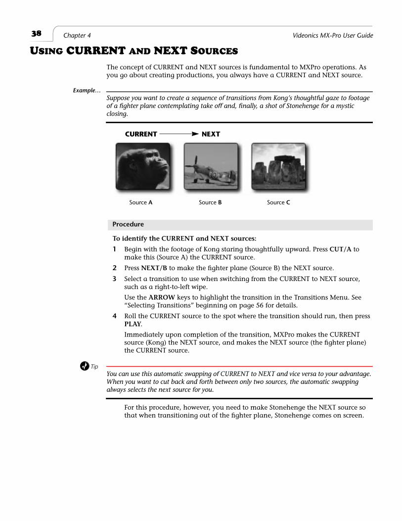
Example…Suppose you want to create a sequence of transitions from Kong’s thoughtful gaze to footage of a fighter plane contemplating take off and, finally, a shot of Stonehenge for a mystic closing.
Procedure
To identify the CURRENT and NEXT sources:
1 Begin with the footage of Kong staring thoughtfully upward. Press CUT/A to make this (Source A) the CURRENT source.
2 Press NEXT/B to make the fighter plane (Source B) the NEXT source.
3 Select a transition to use when switching from the CURRENT to NEXT source, such as a right-to-left wipe.
Use the ARROW keys to highlight the transition in the Transitions Menu. See “Selecting Transitions” beginning on page 56 for details.
4 Roll the CURRENT source to the spot where the transition should run, then press PLAY.
Immediately upon completion of the transition, MXPro makes the CURRENT source (Kong) the NEXT source, and makes the NEXT source (the fighter plane) the CURRENT source.
TipYou can use this automatic swapping of CURRENT to NEXT and vice versa to your advantage. When you want to cut back and forth between only two sources, the automatic swapping always selects the next source for you.
For this procedure, however, you need to make Stonehenge the NEXT source so that when transitioning out of the fighter plane, Stonehenge comes on screen.
CURRENT NEXT
Source A Source B Source C
39Basic Operations Selecting Sources
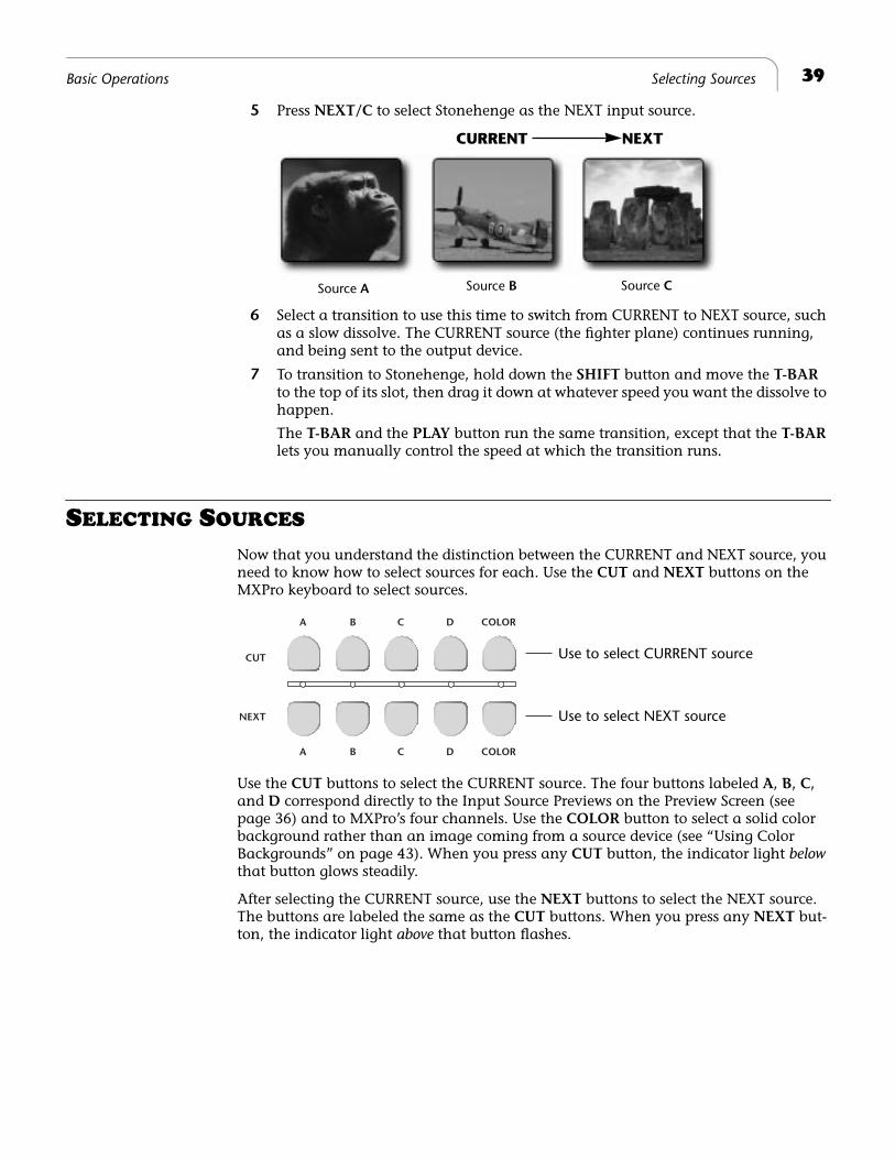
5 Press NEXT/C to select Stonehenge as the NEXT input source.
6 Select a transition to use this time to switch from CURRENT to NEXT source, such as a slow dissolve. The CURRENT source (the fighter plane) continues running, and being sent to the output device.
7 To transition to Stonehenge, hold down the SHIFT button and move the T-BAR to the top of its slot, then drag it down at whatever speed you want the dissolve to happen.
The T-BAR and the PLAY button run the same transition, except that the T-BAR lets you manually control the speed at which the transition runs.
SELECTING SOURCES
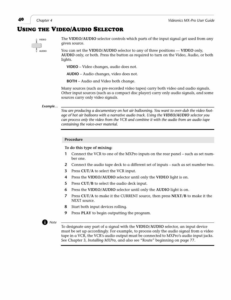
Now that you understand the distinction between the CURRENT and NEXT source, you need to know how to select sources for each. Use the CUT and NEXT buttons on the MXPro keyboard to select sources.
Use the CUT buttons to select the CURRENT source. The four buttons labeled A, B, C, and D correspond directly to the Input Source Previews on the Preview Screen (see page 36) and to MXPro’s four channels. Use the COLOR button to select a solid color background rather than an image coming from a source device (see “Using Color Backgrounds” on page 43). When you press any CUT button, the indicator light below that button glows steadily.
After selecting the CURRENT source, use the NEXT buttons to select the NEXT source. The buttons are labeled the same as the CUT buttons. When you press any NEXT but-ton, the indicator light above that button flashes.
CURRENT NEXT
Source B Source CSource A
CUT
NEXT
A B C D COLOR
A B C D COLOR
Use to select CURRENT source
Use to select NEXT source
40 Chapter 4 Videonics MX-Pro User Guide
USING THE VIDEO/AUDIO SELECTOR
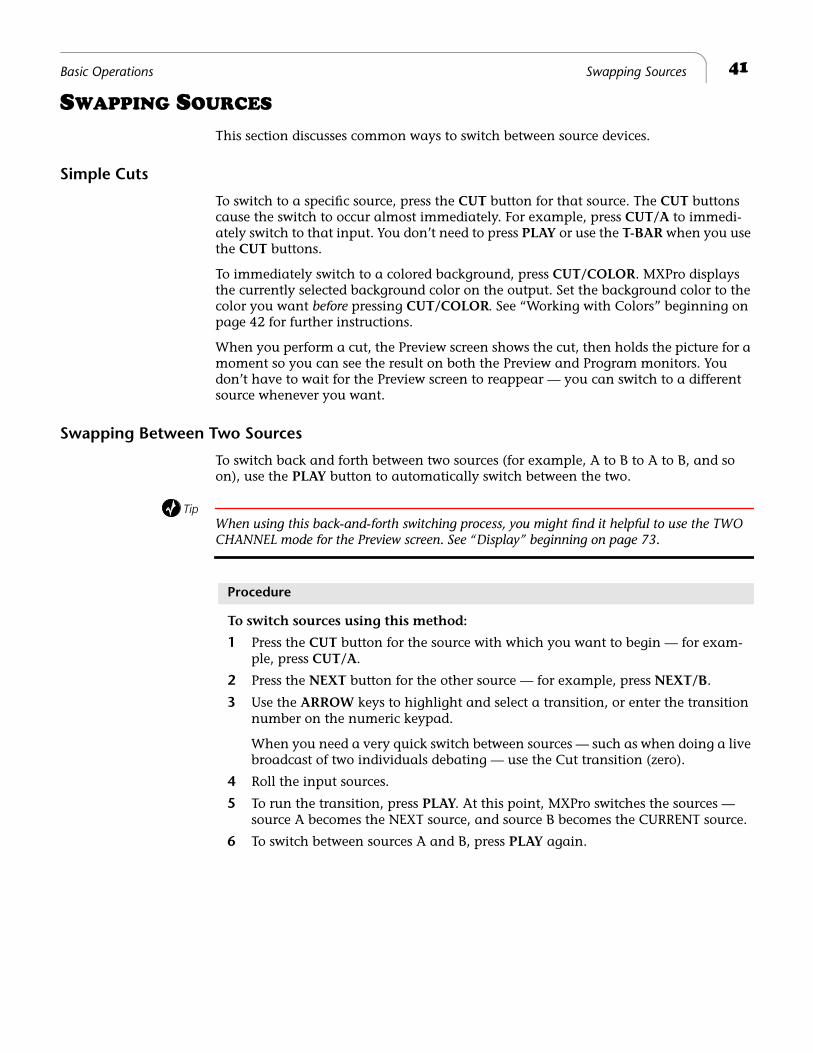
The VIDEO/AUDIO selector controls which parts of the input signal get used from any given source.
You can set the VIDEO/AUDIO selector to any of three positions — VIDEO only, AUDIO only, or both. Press the button as required to turn on the Video, Audio, or both lights.
VIDEO – Video changes, audio does not.
AUDIO – Audio changes, video does not.
BOTH – Audio and Video both change.
Many sources (such as pre-recorded video tapes) carry both video and audio signals. Other input sources (such as a compact disc player) carry only audio signals, and some sources carry only video signals.
Example…You are producing a documentary on hot air ballooning. You want to over-dub the video foot-age of hot air balloons with a narrative audio track. Using the VIDEO/AUDIO selector you can process only the video from the VCR and combine it with the audio from an audio tape containing the voice-over material.
Procedure
To do this type of mixing:
1 Connect the VCR to one of the MXPro inputs on the rear panel – such as set num-ber one.
2 Connect the audio tape deck to a different set of inputs – such as set number two.
3 Press CUT/A to select the VCR input.
4 Press the VIDEO/AUDIO selector until only the VIDEO light is on.
5 Press CUT/B to select the audio deck input.
6 Press the VIDEO/AUDIO selector until only the AUDIO light is on.
7 Press CUT/A to make it the CURRENT source, then press NEXT/B to make it the NEXT source.
8 Start both input devices rolling.
9 Press PLAY to begin outputting the program.
NoteTo designate any part of a signal with the VIDEO/AUDIO selector, an input device must be set up accordingly. For example, to process only the audio signal from a video tape in a VCR, the VCR’s audio output must be connected to MXPro’s audio input jacks. See Chapter 3, Installing MXPro, and also see “Route” beginning on page 77.
VIDEO
AUDIO
41Basic Operations Swapping Sources
SWAPPING SOURCES
This section discusses common ways to switch between source devices.
Simple Cuts
To switch to a specific source, press the CUT button for that source. The CUT buttons cause the switch to occur almost immediately. For example, press CUT/A to immedi-ately switch to that input. You don’t need to press PLAY or use the T-BAR when you use the CUT buttons.
To immediately switch to a colored background, press CUT/COLOR. MXPro displays the currently selected background color on the output. Set the background color to the color you want before pressing CUT/COLOR. See “Working with Colors” beginning on page 42 for further instructions.
When you perform a cut, the Preview screen shows the cut, then holds the picture for a moment so you can see the result on both the Preview and Program monitors. You don’t have to wait for the Preview screen to reappear — you can switch to a different source whenever you want.
Swapping Between Two Sources
To switch back and forth between two sources (for example, A to B to A to B, and so on), use the PLAY button to automatically switch between the two.
TipWhen using this back-and-forth switching process, you might find it helpful to use the TWO CHANNEL mode for the Preview screen. See “Display” beginning on page 73.
Procedure
To switch sources using this method:
1 Press the CUT button for the source with which you want to begin — for exam-ple, press CUT/A.
2 Press the NEXT button for the other source — for example, press NEXT/B.
3 Use the ARROW keys to highlight and select a transition, or enter the transition number on the numeric keypad.
When you need a very quick switch between sources — such as when doing a live broadcast of two individuals debating — use the Cut transition (zero).
4 Roll the input sources.
5 To run the transition, press PLAY. At this point, MXPro switches the sources — source A becomes the NEXT source, and source B becomes the CURRENT source.
6 To switch between sources A and B, press PLAY again.
42 Chapter 4 Videonics MX-Pro User Guide
WORKING WITH COLORS
Common uses for color include solid colored backgrounds and colored borders around objects. So, you need to know how to choose colors and identify those you’ve chosen.
MXPro gives each color a unique number ranging from 0 (zero) to 9. The following table defines these colors and their code numbers.
The maximum number of colors in the MXPro palette is ten. You can change nine of the ten colors. You cannot change Black.
a. You cannot modify Black (color code 0).
Identifying Colors
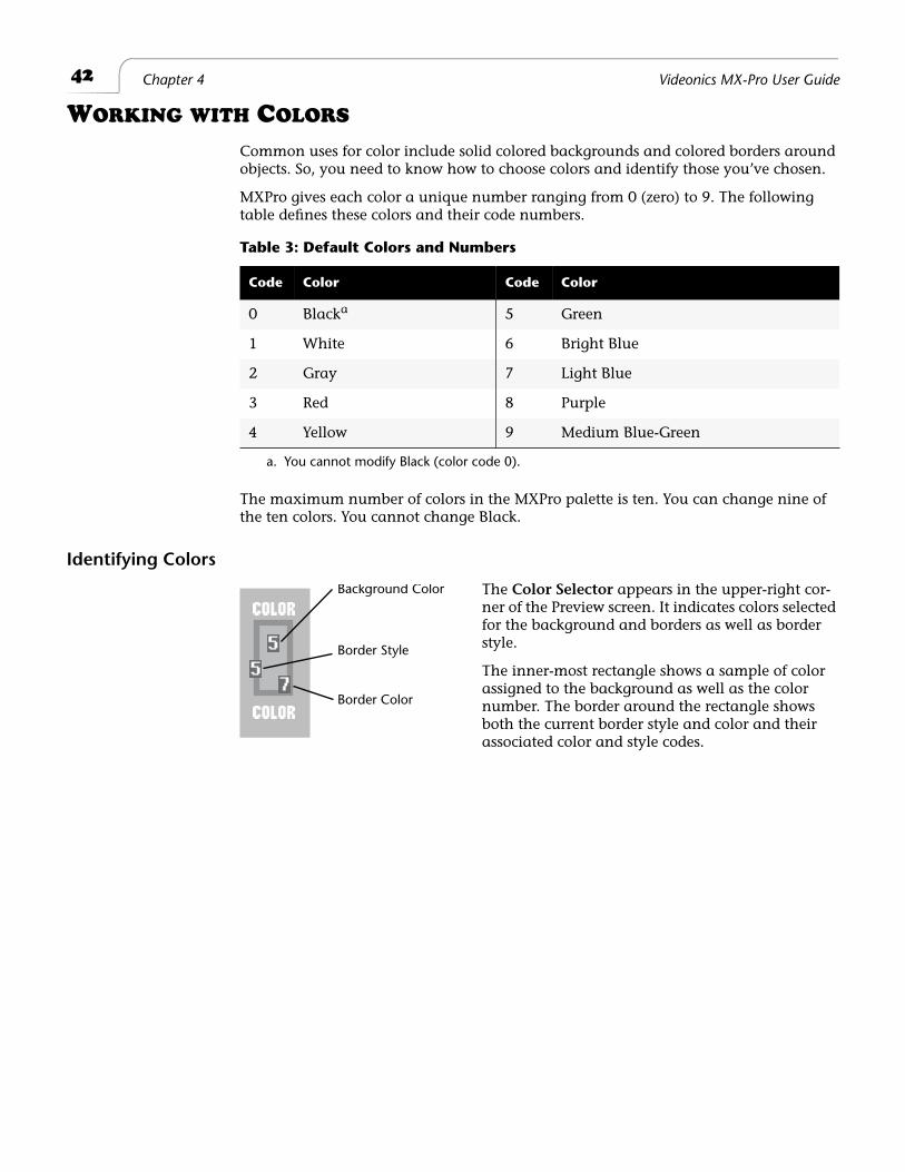
The Color Selector appears in the upper-right cor-ner of the Preview screen. It indicates colors selected for the background and borders as well as border style.
The inner-most rectangle shows a sample of color assigned to the background as well as the color number. The border around the rectangle shows both the current border style and color and their associated color and style codes.
Table 3: Default Colors and Numbers
Code Color Code Color
0 Blacka 5 Green
1 White 6 Bright Blue
2 Gray 7 Light Blue
3 Red 8 Purple
4 Yellow 9 Medium Blue-Green
Background Color
Border Style
Border Color
43Basic Operations Using Color Backgrounds
Using Color Backgrounds
Colored backgrounds have many uses. For example, to dissolve to a solid black back-ground when transitioning out of the CURRENT source, hold the black for a moment or two, then dissolve from the black background into the NEXT source.
TipUse the solid color background to lay down ten seconds of Black at the beginning of your video.
Transition into and out of solid colored backgrounds basically the same way as transi-tioning between sources. The difference is that you must select the background color you want to use before running the transition.
Procedure
To make the selection:
1 Press BG COLOR until the color you want appears in the Color Selector.
2 To immediately cut to the colored background, press CUT/COLOR.
To transition into the colored background, press NEXT/COLOR, then press PLAY or use the T-BAR to switch to the colored background.
Changing Colors and Styles
Use the BG COLOR, BORDER COLOR, and BORDER STYLE buttons to change colors and styles. In each case, press the button repeatedly to cycle through all of the avail-able options for that particular setting.
Procedure
If you already know the color number of the color you want to assign:
1 Press and hold either BG COLOR or BORDER COLOR, depending on which you want to change.
2 Enter the color number on the numeric keypad. For example, press and hold BG COLOR, then press 6 to specify bright blue.
BG COLOR
BORDER COLOR
BORDER STYLE
The following sections describe the BG COLOR, BORDER COLOR, and BORDER STYLE buttons.
44 Chapter 4 Videonics MX-Pro User Guide
Creating Custom Colors
You can change any color other than Black (see Table 3 on page 42) to create custom colors. You cannot add more colors, but you can change the existing ones. Once you create a custom color, it stays permanently in the MXPro unit until and unless you change it again.
BG COLOR and BORDER COLOR share the color palette. Therefore, changing any color affects both the background and border colors.
Procedure
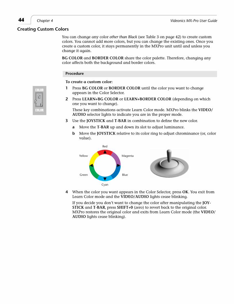
To create a custom color:
1 Press BG COLOR or BORDER COLOR until the color you want to change appears in the Color Selector.
2 Press LEARN+BG COLOR or LEARN+BORDER COLOR (depending on which one you want to change).
These key combinations activate Learn Color mode. MXPro blinks the VIDEO/AUDIO selector lights to indicate you are in the proper mode.
3 Use the JOYSTICK and T-BAR in combination to define the new color.
a Move the T-BAR up and down its slot to adjust luminance.
b Move the JOYSTICK relative to its color ring to adjust chrominance (or, color value).
4 When the color you want appears in the Color Selector, press OK. You exit from Learn Color mode and the VIDEO/AUDIO lights cease blinking.
If you decide you don’t want to change the color after manipulating the JOY-STICK and T-BAR, press SHIFT+0 (zero) to revert back to the original color. MXPro restores the original color and exits from Learn Color mode (the VIDEO/AUDIO lights cease blinking).
Red
Cyan
Yellow
Green
Magenta
Blue
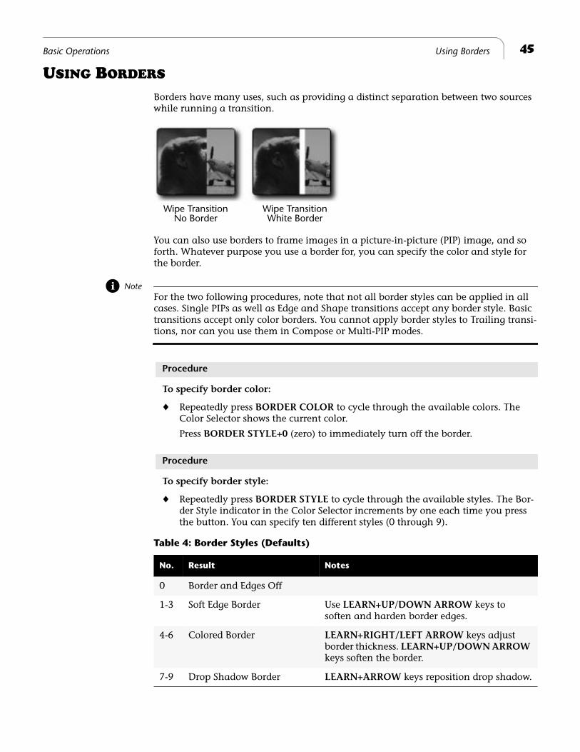
45Basic Operations Using Borders
USING BORDERS
Borders have many uses, such as providing a distinct separation between two sources while running a transition.
You can also use borders to frame images in a picture-in-picture (PIP) image, and so forth. Whatever purpose you use a border for, you can specify the color and style for the border.
NoteFor the two following procedures, note that not all border styles can be applied in all cases. Single PIPs as well as Edge and Shape transitions accept any border style. Basic transitions accept only color borders. You cannot apply border styles to Trailing transi-tions, nor can you use them in Compose or Multi-PIP modes.
Procedure
To specify border color:
¨ Repeatedly press BORDER COLOR to cycle through the available colors. The Color Selector shows the current color.
Press BORDER STYLE+0 (zero) to immediately turn off the border.
Procedure
To specify border style:
¨ Repeatedly press BORDER STYLE to cycle through the available styles. The Bor-der Style indicator in the Color Selector increments by one each time you press the button. You can specify ten different styles (0 through 9).
Wipe TransitionNo Border
Wipe TransitionWhite Border
Table 4: Border Styles (Defaults)
No. Result Notes
0 Border and Edges Off
1-3 Soft Edge Border Use LEARN+UP/DOWN ARROW keys to soften and harden border edges.
4-6 Colored Border LEARN+RIGHT/LEFT ARROW keys adjust border thickness. LEARN+UP/DOWN ARROW keys soften the border.
7-9 Drop Shadow Border LEARN+ARROW keys reposition drop shadow.
46 Chapter 4 Videonics MX-Pro User Guide
Changing Border Styles
This section explains how to specify different edges, color borders, and drop shadows to use in conjunction with border styles.
Procedure
To change a border style setting
1 While the Preview screen is displayed, enter BORDER STYLE+# — where # can range from 1 to 9 (inclusive) and is the number of the border style you want to change, as shown in Table 4, Border Styles (Defaults), above.
2 Select the shape or edge to which you want to add a border or shadow by select-ing an appropriate transition.
TipTry using transitions 300-305 for edges and 554-562 for shapes.
3 Move the T-BAR to its mid point.
4 Press LEARN+BORDER STYLE to select a soft edge, color border, or drop shadow
TipMake note of the border style number you are changing for future reference.You can also use PIP to select and modify border styles for shapes.
5 Use LEARN+ARROW KEYS (as indicated in Table 5, Keys for Changing Border Attributes, below) to specify what you want to change – thickness, softness, or position.
6 Return the T-BAR to its full up or full down position.
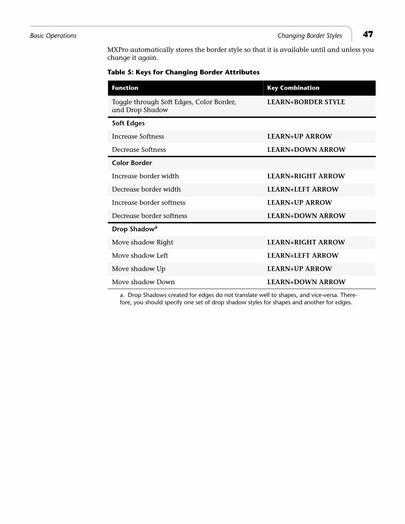
47Basic Operations Changing Border Styles
MXPro automatically stores the border style so that it is available until and unless you change it again.
a. Drop Shadows created for edges do not translate well to shapes, and vice-versa. There-fore, you should specify one set of drop shadow styles for shapes and another for edges.
Table 5: Keys for Changing Border Attributes
Function Key Combination
Toggle through Soft Edges, Color Border, and Drop Shadow
LEARN+BORDER STYLE
Soft Edges
Increase Softness LEARN+UP ARROW
Decrease Softness LEARN+DOWN ARROW
Color Border
Increase border width LEARN+RIGHT ARROW
Decrease border width LEARN+LEFT ARROW
Increase border softness LEARN+UP ARROW
Decrease border softness LEARN+DOWN ARROW
Drop Shadowa
Move shadow Right LEARN+RIGHT ARROW
Move shadow Left LEARN+LEFT ARROW
Move shadow Up LEARN+UP ARROW
Move shadow Down LEARN+DOWN ARROW

®
Notes
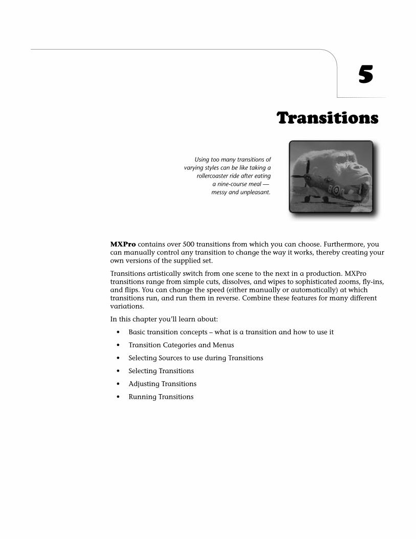
5
Transitions
MXPro
contains over 500 transitions from which you can choose. Furthermore, you can manually control any transition to change the way it works, thereby creating your own versions of the supplied set.
Transitions artistically switch from one scene to the next in a production. MXPro transitions range from simple cuts, dissolves, and wipes to sophisticated zooms, fly-ins, and flips. You can change the speed (either manually or automatically) at which transitions run, and run them in reverse. Combine these features for many different variations.
In this chapter you’ll learn about:
• Basic transition concepts – what is a transition and how to use it
• Transition Categories and Menus
• Selecting Sources to use during Transitions
• Selecting Transitions
• Adjusting Transitions
• Running Transitions
Using too many transitions ofvarying styles can be like taking a
rollercoaster ride after eatinga nine-course meal — messy and unpleasant.
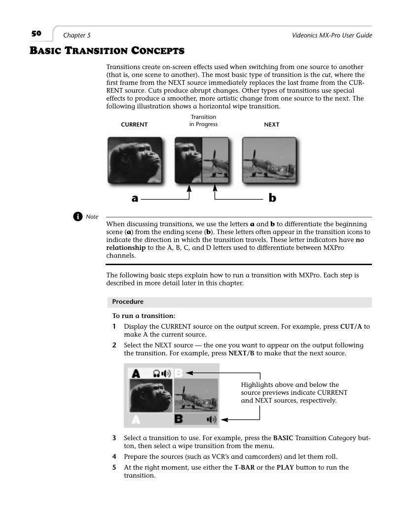
50
Chapter 5 Videonics MX-Pro User Guide
B
ASIC
T
RANSITION
C
ONCEPTS
Transitions create on-screen effects used when switching from one source to another (that is, one scene to another). The most basic type of transition is the
cut
, where the first frame from the NEXT source immediately replaces the last frame from the CUR-RENT source. Cuts produce abrupt changes. Other types of transitions use special effects to produce a smoother, more artistic change from one source to the next. The following illustration shows a horizontal wipe transition.
Note
When discussing transitions, we use the letters
a
and
b
to differentiate the beginning scene (
a
) from the ending scene (
b
). These letters often appear in the transition icons to indicate the direction in which the transition travels. These letter indicators have
no relationship
to the A, B, C, and D letters used to differentiate between MXPro
channels.
The following basic steps explain how to run a transition with MXPro. Each step is described in more detail later in this chapter.
Procedure
To run a transition:
1
Display the CURRENT source on the output screen. For example, press
CUT/A
to make A the current source.
2
Select the NEXT source — the one you want to appear on the output following the transition. For example, press
NEXT/B
to make that the next source.
3
Select a transition to use. For example, press the
BASIC
Transition Category but-ton, then select a wipe transition from the menu.
4
Prepare the sources (such as VCR’s and camcorders) and let them roll.
5
At the right moment, use either the
T-BAR
or the
PLAY
button to run the transition.
Transitionin ProgressCURRENT NEXT
a b
Highlights above and below the source previews indicate CURRENT and NEXT sources, respectively.
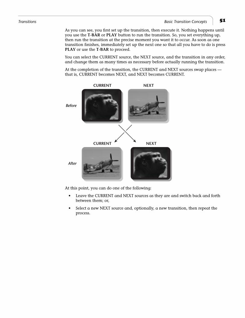
51
Transitions Basic Transition Concepts
As you can see, you first set up the transition, then execute it. Nothing happens until you use the
T-BAR
or
PLAY
button to run the transition. So, you set everything up, then run the transition at the precise moment you want it to occur. As soon as one transition finishes, immediately set up the next one so that all you have to do is press
PLAY
or use the
T-BAR
to proceed.
You can select the CURRENT source, the NEXT source, and the transition in any order, and change them as many times as necessary before actually running the transition.
At the completion of the transition, the CURRENT and NEXT sources swap places — that is, CURRENT becomes NEXT, and NEXT becomes CURRENT.
At this point, you can do one of the following:
• Leave the CURRENT and NEXT sources as they are and switch back and forth between them; or,
• Select a new NEXT source and, optionally, a new transition, then repeat the process.
CURRENT NEXT
NEXTCURRENT
Before
After
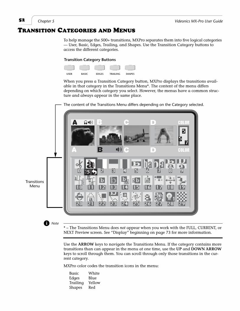
52
Chapter 5 Videonics MX-Pro User Guide
T
RANSITION
C
ATEGORIES
AND
M
ENUS
To help manage the 500+ transitions, MXPro separates them into five logical categories — User, Basic, Edges, Trailing, and Shapes. Use the Transition Category buttons to access the different categories.
When you press a Transition Category button, MXPro displays the transitions avail-able in that category in the Transitions Menu*. The content of the menu differs depending on which category you select. However, the menus have a common struc-ture and always appear in the same place.
Note
* – The Transitions Menu does
not
appear when you work with the FULL, CURRENT, or
NEXT Preview screen. See “Display” beginning on page 73 for more information.
Use the
ARROW
keys to navigate the Transitions Menu. If the category contains more transitions than can appear in the menu at one time, use the
UP
and
DOWN ARROW
keys to scroll through them. You can scroll through only those transitions in the cur-rent category.
MXPro color codes the transition icons in the menu:
Basic WhiteEdges BlueTrailing YellowShapes Red
USER BASIC EDGES TRAILING SHAPES
Transition Category Buttons
The content of the Transitions Menu differs depending on the Category selected.
TransitionsMenu
53
Transitions Basic Transitions Category
Basic Transitions Category
This category includes common transitions, such as wipes and dissolves. The transi-tions in this category are color coded White. See page 132 for samples of the icons in this category.
MX-1 Compatibility
If you are upgrading to MXPro from the Videonics MX-1 Video Mixer, the transitions in the Basic category are the same as the MX-1.
MXPro provides a set of hot keys that directly correspond to the MX-1 Effect buttons. Using the hot keys (in the following table) causes the MXPro Preview screen cursor to appear at the beginning of each section within the Basic (MX-1) category.
Edges Transitions Category
These transitions move a curved or jagged edge across the screen when transitioning to a different picture source. Transitions in this category are color coded Blue. See page 137 for samples.
Trailing Transitions Category
The transitions in this category leave a trail of images on the screen as a change occurs. The trailing images go away once the transition finishes. Transitions in this cat-egory are color coded Yellow. See page 138 for samples.
Shapes Transitions Category
These transitions occur as a wipe in the shape of a geometric object, such as a heart, a five-pointed star, a circle, and so forth. Transitions are color coded Red. See page 139 for samples.
User Transitions Category
It’s
unlikely
you’ll use all of the available transitions — but it is
likely
that you’ll have a limited set you use most of the time. With this in mind, MXPro makes it easy for you to access your favorite transitions by creating your own personal menu — the User menu. MXPro comes with a default set, but you can add and remove them to tailor the User menu to your preferences and needs.
Table 6: MX-1 Compatibility Hot Keys
MX-1 Function MXPro Hot Key
Fades and Dissolves(Positions cursor at transition 160)
SHIFT+BASIC
Wipes(Positions cursor at transition 30)
SHIFT+EDGES
Zooms(Positions cursor at transition 188)
SHIFT+TRAILING
Flips(Positions cursor at transition 210)
SHIFT+SHAPES
54
Chapter 5 Videonics MX-Pro User Guide
Tip
During production planning, determine which transitions you want to use, then set up the User category to contain those transitions. This gives you quick, immediate access to the tran-sitions you intend to use without having to search through the other categories. See the follow-ing section (“Changing User Transitions Menu”) to learn how to tailor the menu to your
preferences.
C
HANGING
U
SER
T
RANSITIONS
M
ENU
The first time you power up MXPro and press the
USER
Transitions Category button, the default transitions appear in the menu. The default set contains a variety of transi-tions from the other four categories, as defined by Videonics at the factory. If you are satisfied with the default set, there is no need to change them.
The
USER
category does not contain distinct transitions – that is, all transitions in the
USER
category actually exist in other categories (Basic, Edges, Trailing, and Shape). Think of the
USER
category as a collection of references to other transitions.
You can change as many transitions in the
USER
menu as you want.
Procedure
To change a transition in the User menu:
1
Decide which transition you want to add to the
USER
category. Refer to Appen-dix A,
Transitions List
, for a list of valid numbers and their associated transitions.
2
If necessary, press
DISPLAY
to set the Preview screen to STANDARD or TWO CHANNEL mode.
In the other Preview modes (FULL, CURRENT, or NEXT), MXPro does not display the Transitions Menu. See “Display” beginning on page 73.
3
Press the
USER
Transition Category button to display the menu on the Preview screen.
4
Use the
ARROW
keys to highlight the transition you want to replace in the
USER
category.
5
Enter the number of the transition you selected in step 1, above. You can enter the number of any transition from any category.
6
Press
OK
.
Restoring Default UserTransitions
You can easily restore the default set of transitions in the User category.
Procedure
To restore the default set of transition to the User menu:
1
If necessary, press the
USER
Transition Category button to display that menu on the Preview screen.
2
Enter
SHIFT+0 (zero). This restores the default set of transitions for this category.
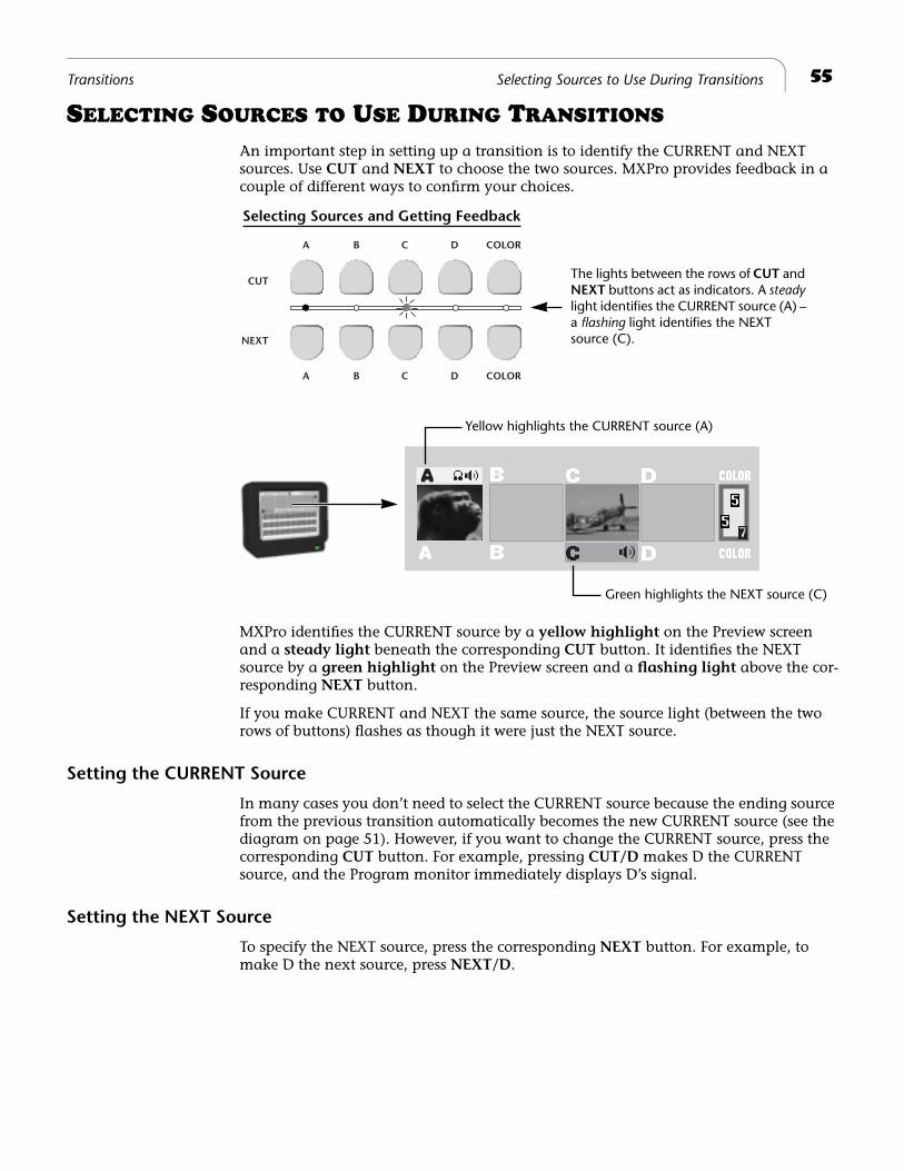
55Transitions Selecting Sources to Use During Transitions
SELECTING SOURCES TO USE DURING TRANSITIONS
An important step in setting up a transition is to identify the CURRENT and NEXT sources. Use CUT and NEXT to choose the two sources. MXPro provides feedback in a couple of different ways to confirm your choices.
MXPro identifies the CURRENT source by a yellow highlight on the Preview screen and a steady light beneath the corresponding CUT button. It identifies the NEXT source by a green highlight on the Preview screen and a flashing light above the cor-responding NEXT button.
If you make CURRENT and NEXT the same source, the source light (between the two rows of buttons) flashes as though it were just the NEXT source.
Setting the CURRENT Source
In many cases you don’t need to select the CURRENT source because the ending source from the previous transition automatically becomes the new CURRENT source (see the diagram on page 51). However, if you want to change the CURRENT source, press the corresponding CUT button. For example, pressing CUT/D makes D the CURRENT source, and the Program monitor immediately displays D’s signal.
Setting the NEXT Source
To specify the NEXT source, press the corresponding NEXT button. For example, to make D the next source, press NEXT/D.
CUT
NEXT
A B C D COLOR
A B C D COLOR
The lights between the rows of CUT and NEXT buttons act as indicators. A steady light identifies the CURRENT source (A) – a flashing light identifies the NEXT source (C).
Selecting Sources and Getting Feedback
Yellow highlights the CURRENT source (A)
Green highlights the NEXT source (C)
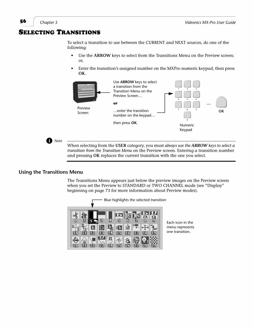
56 Chapter 5 Videonics MX-Pro User Guide
SELECTING TRANSITIONS
To select a transition to use between the CURRENT and NEXT sources, do one of the following:
• Use the ARROW keys to select from the Transitions Menu on the Preview screen; or,
• Enter the transition’s assigned number on the MXPro numeric keypad, then press OK.
NoteWhen selecting from the USER category, you must always use the ARROW keys to select a transition from the Transition Menu on the Preview screen. Entering a transition number and pressing OK replaces the current transition with the one you select.
Using the Transitions Menu
The Transitions Menu appears just below the preview images on the Preview screen when you set the Preview to STANDARD or TWO CHANNEL mode (see “Display” beginning on page 73 for more information about Preview modes).
1
4
7
2
5
8
0
3
6
9OK
PreviewScreen
NumericKeypad
Use ARROW keys to select a transition from the Transition Menu on the Preview Screen…
or
…enter the transition number on the keypad…
then press OK.
…
Blue highlights the selected transition
Each icon in the menu represents one transition.
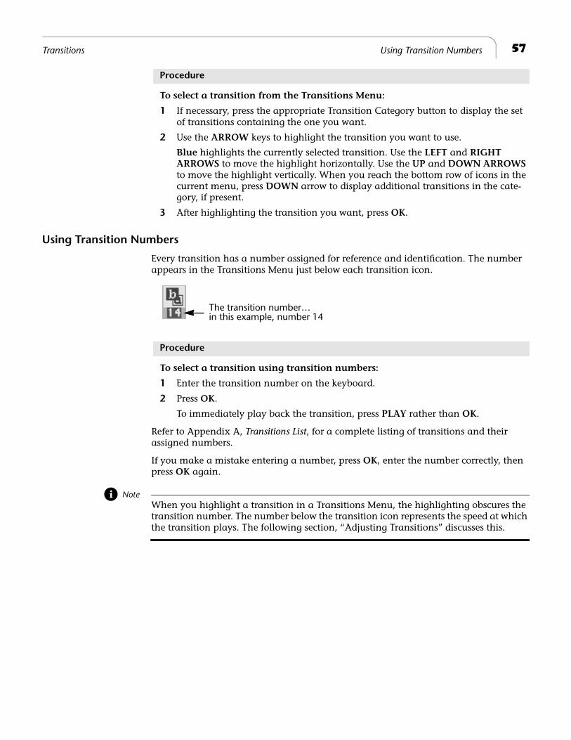
57Transitions Using Transition Numbers
Procedure
To select a transition from the Transitions Menu:
1 If necessary, press the appropriate Transition Category button to display the set of transitions containing the one you want.
2 Use the ARROW keys to highlight the transition you want to use.
Blue highlights the currently selected transition. Use the LEFT and RIGHT ARROWS to move the highlight horizontally. Use the UP and DOWN ARROWS to move the highlight vertically. When you reach the bottom row of icons in the current menu, press DOWN arrow to display additional transitions in the cate-gory, if present.
3 After highlighting the transition you want, press OK.
Using Transition Numbers
Every transition has a number assigned for reference and identification. The number appears in the Transitions Menu just below each transition icon.
Procedure
To select a transition using transition numbers:
1 Enter the transition number on the keyboard.
2 Press OK.
To immediately play back the transition, press PLAY rather than OK.
Refer to Appendix A, Transitions List, for a complete listing of transitions and their assigned numbers.
If you make a mistake entering a number, press OK, enter the number correctly, then press OK again.
NoteWhen you highlight a transition in a Transitions Menu, the highlighting obscures the transition number. The number below the transition icon represents the speed at which the transition plays. The following section, “Adjusting Transitions” discusses this.
The transition number…in this example, number 14
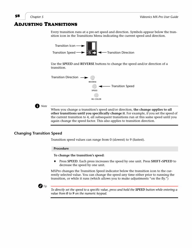
58 Chapter 5 Videonics MX-Pro User Guide
ADJUSTING TRANSITIONS
Every transition runs at a pre-set speed and direction. Symbols appear below the tran-sition icon in the Transitions Menu indicating the current speed and direction.
Use the SPEED and REVERSE buttons to change the speed and/or direction of a transition.
NoteWhen you change a transition’s speed and/or direction, the change applies to all other transitions until you specifically change it. For example, if you set the speed of the current transition to 4, all subsequent transitions run at this same speed until you again change the speed factor. This also applies to transition direction.
Changing Transition Speed
Transition speed values can range from 0 (slowest) to 9 (fastest).
Procedure
To change the transition’s speed:
¨ Press SPEED. Each press increases the speed by one unit. Press SHIFT+SPEED to decrease the speed by one unit.
MXPro changes the Transition Speed indicator below the transition icon to the cur-rently selected value. You can change the speed any time either prior to running the transition, or while it runs (which allows you to make adjustments “on the fly.”)
TipTo directly set the speed to a specific value, press and hold the SPEED button while entering a value from 0 to 9 on the numeric keypad.
Transition Speed Transition Direction
Transition Icon
REVERSE
SPEED
BG COLOR
Transition Direction
Transition Speed
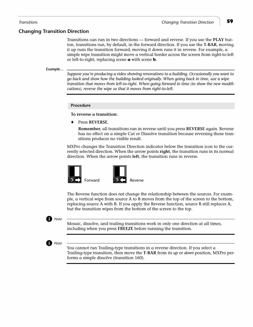
59Transitions Changing Transition Direction
Changing Transition Direction
Transitions can run in two directions — forward and reverse. If you use the PLAY but-ton, transitions run, by default, in the forward direction. If you use the T-BAR, moving it up runs the transition forward; moving it down runs it in reverse. For example, a simple wipe transition might move a vertical border across the screen from right-to-left or left-to-right, replacing scene a with scene b.
Example…Suppose you’re producing a video showing renovations to a building. Occasionally you want to go back and show how the building looked originally. When going back in time, use a wipe transition that moves from left-to-right. When going forward in time (to show the new modifi-cations), reverse the wipe so that it moves from right-to-left.
Procedure
To reverse a transition:
¨ Press REVERSE.
Remember, all transitions run in reverse until you press REVERSE again. Reverse has no effect on a simple Cut or Dissolve transition because reversing those tran-sitions produces no visible result.
MXPro changes the Transition Direction indicator below the transition icon to the cur-rently selected direction. When the arrow points right, the transition runs in its normal direction. When the arrow points left, the transition runs in reverse.
The Reverse function does not change the relationship between the sources. For exam-ple, a vertical wipe from source A to B moves from the top of the screen to the bottom, replacing source A with B. If you apply the Reverse function, source B still replaces A, but the transition wipes from the bottom of the screen to the top.
NoteMosaic, dissolve, and trailing transitions work in only one direction at all times, including when you press FREEZE before running the transition.
NoteYou cannot run Trailing-type transitions in a reverse direction. If you select a Trailing-type transition, then move the T-BAR from its up or down position, MXPro per-forms a simple dissolve (transition 160).
Forward Reverse
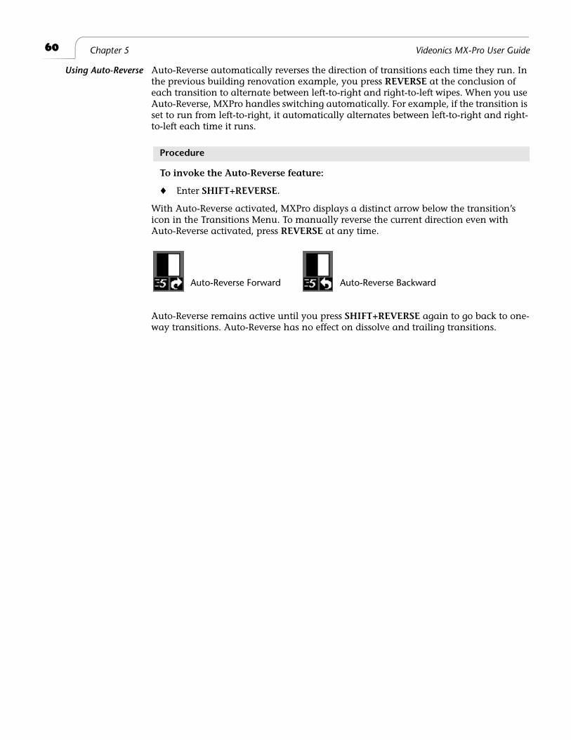
60 Chapter 5 Videonics MX-Pro User Guide
Using Auto-Reverse Auto-Reverse automatically reverses the direction of transitions each time they run. In the previous building renovation example, you press REVERSE at the conclusion of each transition to alternate between left-to-right and right-to-left wipes. When you use Auto-Reverse, MXPro handles switching automatically. For example, if the transition is set to run from left-to-right, it automatically alternates between left-to-right and right-to-left each time it runs.
Procedure
To invoke the Auto-Reverse feature:
¨ Enter SHIFT+REVERSE.
With Auto-Reverse activated, MXPro displays a distinct arrow below the transition’s icon in the Transitions Menu. To manually reverse the current direction even with Auto-Reverse activated, press REVERSE at any time.
Auto-Reverse remains active until you press SHIFT+REVERSE again to go back to one-way transitions. Auto-Reverse has no effect on dissolve and trailing transitions.
Auto-Reverse Forward Auto-Reverse Backward
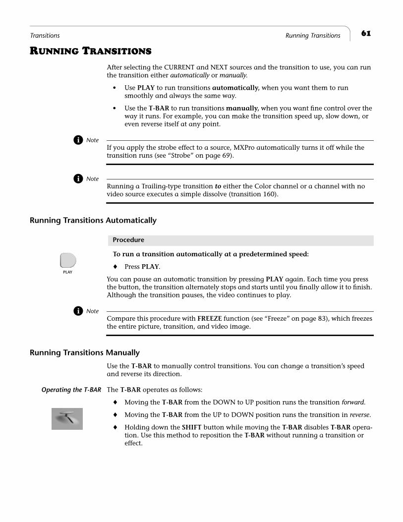
61Transitions Running Transitions
RUNNING TRANSITIONS
After selecting the CURRENT and NEXT sources and the transition to use, you can run the transition either automatically or manually.
• Use PLAY to run transitions automatically, when you want them to run smoothly and always the same way.
• Use the T-BAR to run transitions manually, when you want fine control over the way it runs. For example, you can make the transition speed up, slow down, or even reverse itself at any point.
NoteIf you apply the strobe effect to a source, MXPro automatically turns it off while the transition runs (see “Strobe” on page 69).
NoteRunning a Trailing-type transition to either the Color channel or a channel with no video source executes a simple dissolve (transition 160).
Running Transitions Automatically
Procedure
To run a transition automatically at a predetermined speed:
¨ Press PLAY.
You can pause an automatic transition by pressing PLAY again. Each time you press the button, the transition alternately stops and starts until you finally allow it to finish. Although the transition pauses, the video continues to play.
NoteCompare this procedure with FREEZE function (see “Freeze” on page 83), which freezes the entire picture, transition, and video image.
Running Transitions Manually
Use the T-BAR to manually control transitions. You can change a transition’s speed and reverse its direction.
Operating the T-BAR The T-BAR operates as follows:
¨ Moving the T-BAR from the DOWN to UP position runs the transition forward.
¨ Moving the T-BAR from the UP to DOWN position runs the transition in reverse.
¨ Holding down the SHIFT button while moving the T-BAR disables T-BAR opera-tion. Use this method to reposition the T-BAR without running a transition or effect.
PLAY

®
Notes
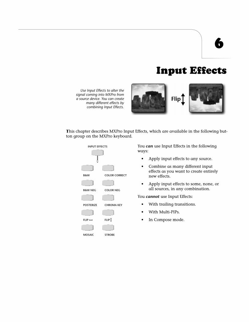
6
Input Effects
T
his chapter describes MXPro Input Effects, which are available in the following but-ton group on the MXPro keyboard.
Flip
Use Input Effects to alter thesignal coming into MXPro froma source device. You can create
many different effects bycombining Input Effects.
INPUT EFFECTS
B&W COLOR CORRECT
B&W NEG COLOR NEG
POSTERIZE CHROMA KEY
FLIP FLIP
MOSAIC STROBE
You can use Input Effects in the following ways:
• Apply input effects to any source.
• Combine as many different input effects as you want to create entirely new effects.
• Apply input effects to some, none, or all sources, in any combination.
You cannot use Input Effects:
• With trailing transitions.
• With Multi-PIPs.
• In Compose mode.
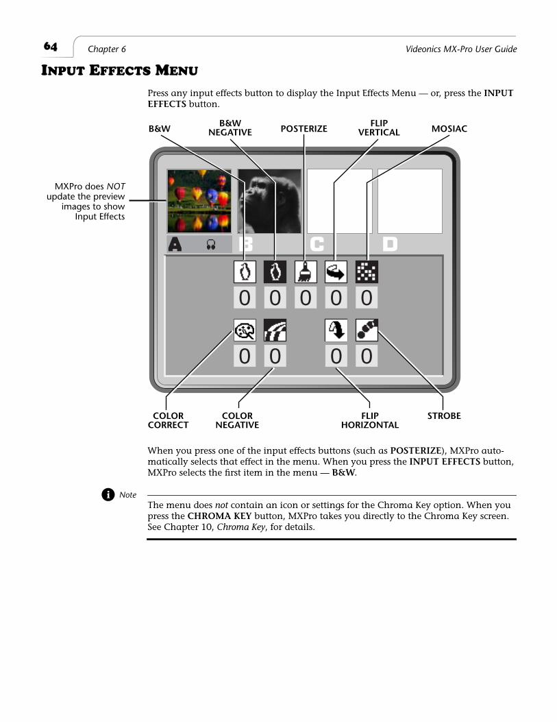
64
Chapter 6 Videonics MX-Pro User Guide
I
NPUT
E
FFECTS
M
ENU
Press any input effects button to display the Input Effects Menu — or, press the
INPUT EFFECTS
button.
When you press one of the input effects buttons (such as
POSTERIZE
), MXPro auto-matically selects that effect in the menu. When you press the
INPUT EFFECTS
button, MXPro selects the first item in the menu —
B&W
.
Note
The menu does
not
contain an icon or settings for the Chroma Key option. When you press the
CHROMA KEY
button, MXPro takes you directly to the Chroma Key screen.
See Chapter 10,
Chroma Key
, for details.
0 0
00
0
0
0
0
0
B&WB&W
POSTERIZEFLIP
MOSIAC
COLOR COLOR FLIP STROBE
NEGATIVE
CORRECT NEGATIVE
VERTICAL
HORIZONTAL
MXPro does NOTupdate the preview
images to showInput Effects
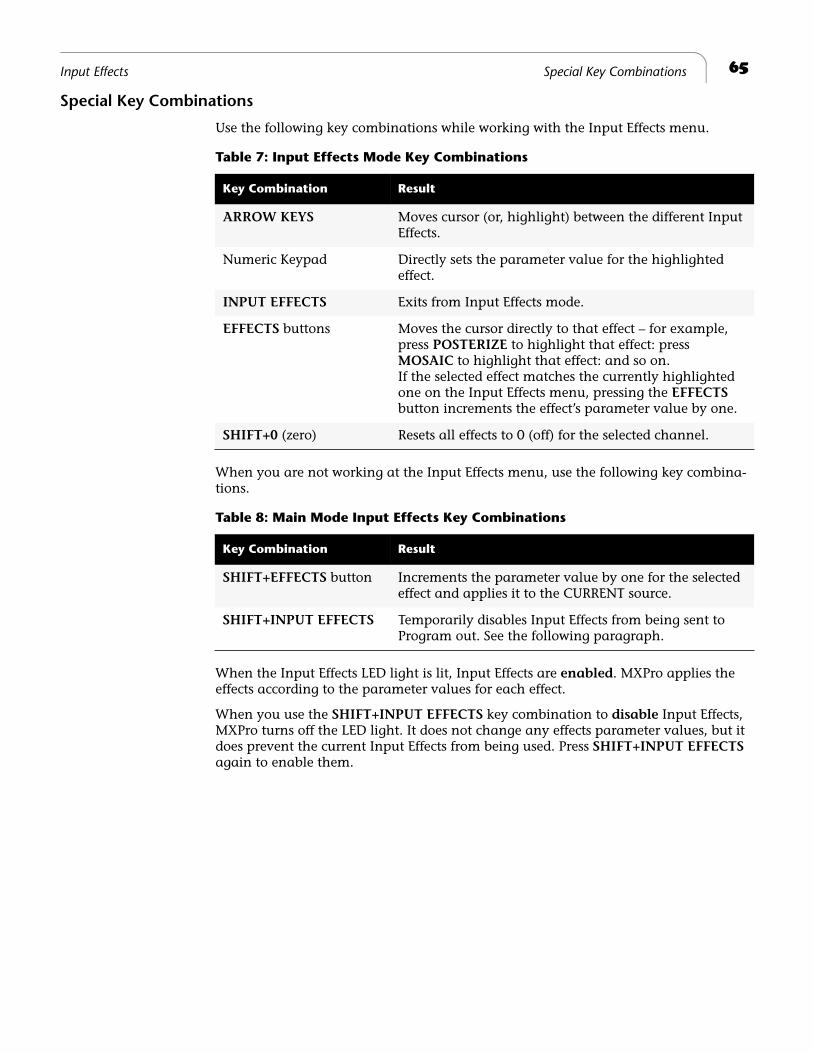
65
Input Effects Special Key Combinations
Special Key Combinations
Use the following key combinations while working with the Input Effects menu.
When you are not working at the Input Effects menu, use the following key combina-tions.
When the Input Effects LED light is lit, Input Effects are
enabled
. MXPro applies the effects according to the parameter values for each effect.
When you use the
SHIFT+INPUT EFFECTS
key combination to
disable
Input Effects, MXPro turns off the LED light. It does not change any effects parameter values, but it does prevent the current Input Effects from being used. Press
SHIFT+INPUT EFFECTS
again to enable them.
Table 7: Input Effects Mode Key Combinations
Key Combination Result
ARROW KEYS
Moves cursor (or, highlight) between the different Input Effects.
Numeric Keypad Directly sets the parameter value for the highlighted effect.
INPUT EFFECTS
Exits from Input Effects mode.
EFFECTS
buttons Moves the cursor directly to that effect – for example, press
POSTERIZE
to highlight that effect: press
MOSAIC
to highlight that effect: and so on.If the selected effect matches the currently highlighted one on the Input Effects menu, pressing the
EFFECTS
button increments the effect’s parameter value by one.
SHIFT+0
(zero) Resets all effects to 0 (off) for the selected channel.
Table 8: Main Mode Input Effects Key Combinations
Key Combination Result
SHIFT+EFFECTS
button Increments the parameter value by one for the selected effect and applies it to the CURRENT source.
SHIFT+INPUT EFFECTS
Temporarily disables Input Effects from being sent to Program out. See the following paragraph.
66
Chapter 6 Videonics MX-Pro User Guide
U
SING
I
NPUT
E
FFECTS
Input effects aren’t visible in the small Preview thumbnails. To make them visible:
1
Make the channel to which the input effects are applied the NEXT source. That is, press
NEXT/A
,
B
,
C
, or
D
.
2
Press the
DISPLAY
button to display the NEXT Preview option (see “Display” beginning on page 73); or use the shortcut
SHIFT+4.
Once you apply an input effect to a channel, it remains in effect at all times (even dur-ing transitions) until you specifically change it, with these exceptions:
• Some effects do not apply to the foreground image while using PIPs, Chroma Key, and Compose.
• MXPro Color Correction turns off during transitions if it is enabled on more than one channel. See “Color Correct” on page 68 for more information.
• MXPro turns off Strobe during transitions.
• MXPro turns off all Input Effects during Trailing transitions.
With the exception of Chroma Key, each input effect has associated with it a “parame-ter” value. In some cases, the value can be either 0 (zero) or 1. In others, it can range from 0 to 9. The Color Correction option also works a little differently: see “Color Cor-rect” on page 68.
Procedure
To apply a parameter value:
1
Press
INPUT EFFECTS
or one of the input effects buttons to display the Input Effects menu.
2
If you haven’t already done so, use the
ARROW
keys or
INPUT EFFECTS
button to select the Input Effect to which you want to apply parameter values.
3
Set the parameter value to
0
(zero) to turn it off, or to
1
to turn it on.
4
Use one of the
NEXT
buttons to select the source to which you want to apply the effect. For example, press
NEXT/B
to apply the effect to channel B.
5
Type the parameter value on the MXPro numeric keypad, or continue pressing the corresponding effects key until the parameter value you want appears in the menu.
6
Press
OK
to exit from Input Effects mode.
MXPro stores the most recent set of input effects. Therefore, when you turn the unit off, then turn it back on again, the most recent selection of input effects is still active.
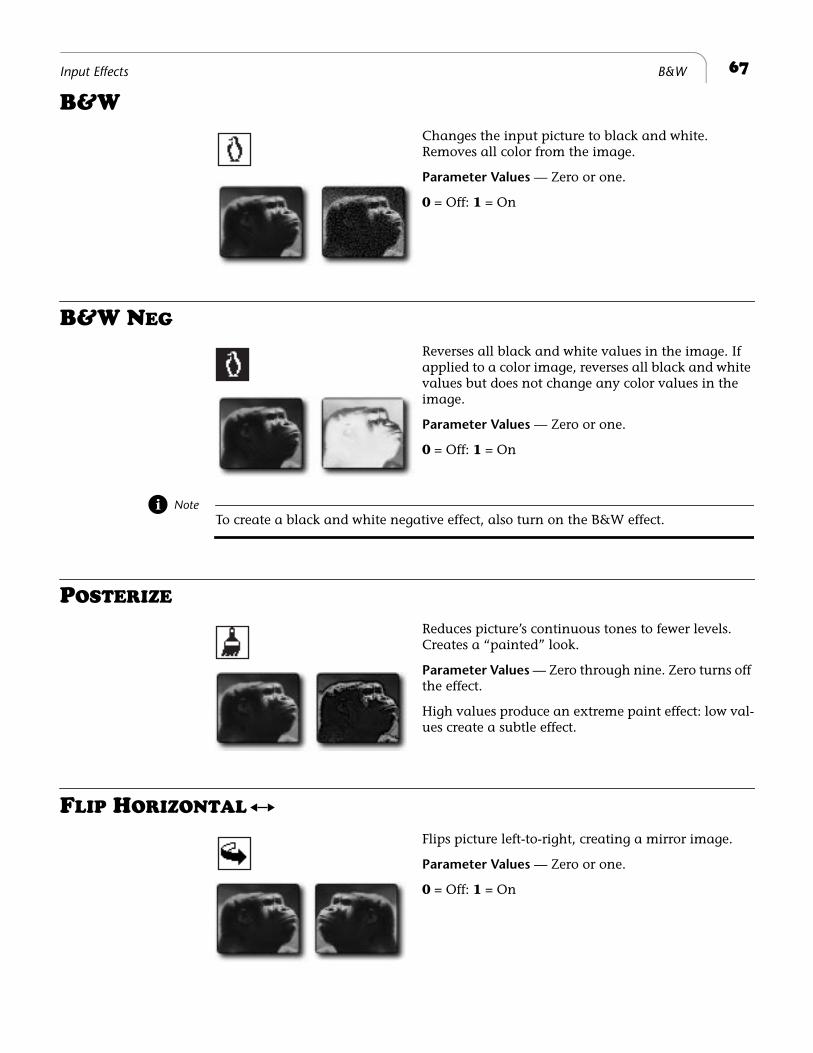
67
Input Effects B&W
B&W
Changes the input picture to black and white. Removes all color from the image.
Parameter Values
— Zero or one.
0
= Off:
1
= On
B&W N
EG
Reverses all black and white values in the image. If applied to a color image, reverses all black and white values but does not change any color values in the image.
Parameter Values
— Zero or one.
0
= Off:
1
= On
Note
To create a black and white negative effect, also turn on the B&W effect.
P
OSTERIZE
Reduces picture’s continuous tones to fewer levels. Creates a “painted” look.
Parameter Values
— Zero through nine. Zero turns off the effect.
High values produce an extreme paint effect: low val-ues create a subtle effect.
F
LIP
H
ORIZONTAL
Flips picture left-to-right, creating a mirror image.
Parameter Values
— Zero or one.
0
= Off:
1
= On
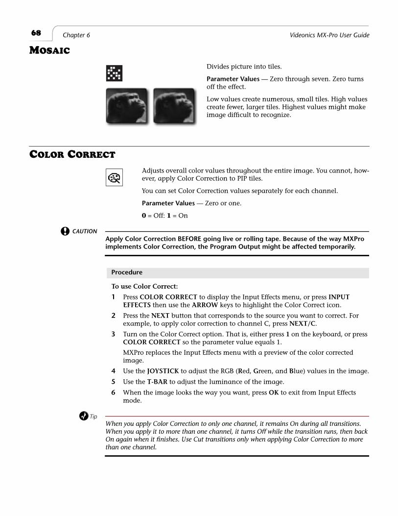
68
Chapter 6 Videonics MX-Pro User Guide
MOSAIC
Divides picture into tiles.
Parameter Values — Zero through seven. Zero turns off the effect.
Low values create numerous, small tiles. High values create fewer, larger tiles. Highest values might make image difficult to recognize.
COLOR CORRECT
Adjusts overall color values throughout the entire image. You cannot, how-ever, apply Color Correction to PIP tiles.
You can set Color Correction values separately for each channel.
Parameter Values — Zero or one.
0 = Off: 1 = On
CAUTIONApply Color Correction BEFORE going live or rolling tape. Because of the way MXPro implements Color Correction, the Program Output might be affected temporarily.
Procedure
To use Color Correct:
1 Press COLOR CORRECT to display the Input Effects menu, or press INPUT EFFECTS then use the ARROW keys to highlight the Color Correct icon.
2 Press the NEXT button that corresponds to the source you want to correct. For example, to apply color correction to channel C, press NEXT/C.
3 Turn on the Color Correct option. That is, either press 1 on the keyboard, or press COLOR CORRECT so the parameter value equals 1.
MXPro replaces the Input Effects menu with a preview of the color corrected image.
4 Use the JOYSTICK to adjust the RGB (Red, Green, and Blue) values in the image.
5 Use the T-BAR to adjust the luminance of the image.
6 When the image looks the way you want, press OK to exit from Input Effects mode.
TipWhen you apply Color Correction to only one channel, it remains On during all transitions. When you apply it to more than one channel, it turns Off while the transition runs, then back On again when it finishes. Use Cut transitions only when applying Color Correction to more than one channel.
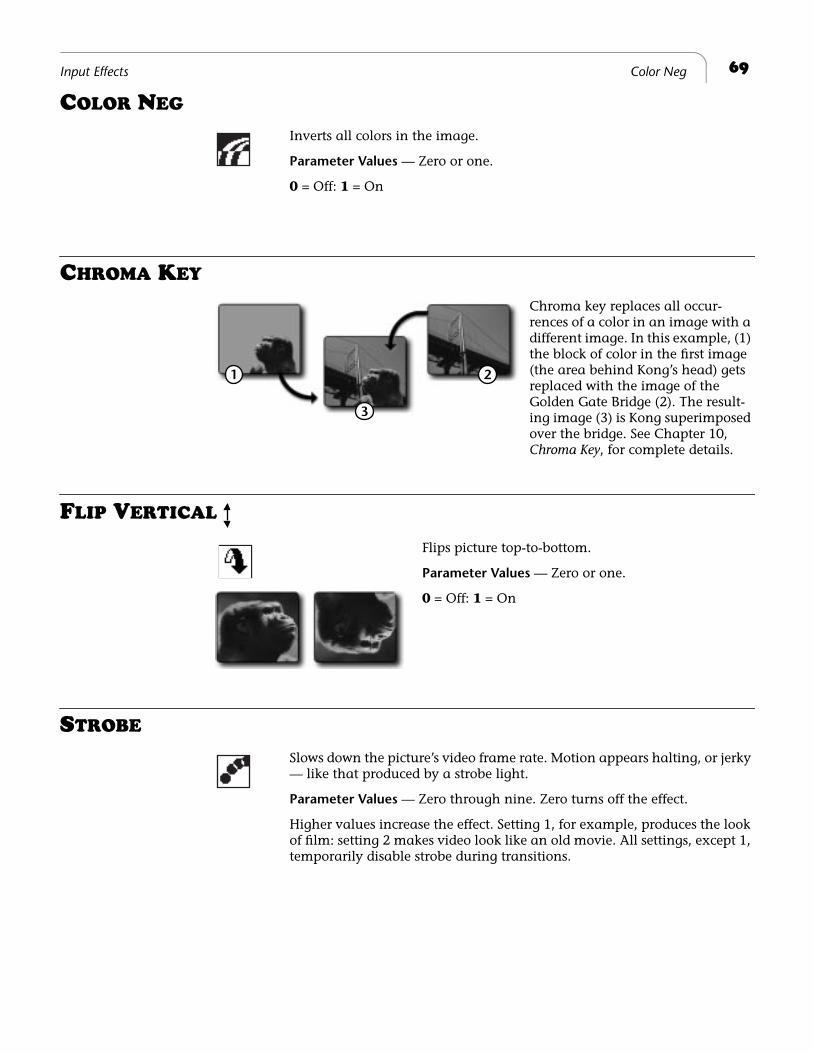
69Input Effects Color Neg
COLOR NEG
Inverts all colors in the image.
Parameter Values — Zero or one.
0 = Off: 1 = On
CHROMA KEY
Chroma key replaces all occur-rences of a color in an image with a different image. In this example, (1) the block of color in the first image (the area behind Kong’s head) gets replaced with the image of the Golden Gate Bridge (2). The result-ing image (3) is Kong superimposed over the bridge. See Chapter 10, Chroma Key, for complete details.
FLIP VERTICAL
Flips picture top-to-bottom.
Parameter Values — Zero or one.
0 = Off: 1 = On
STROBE
Slows down the picture’s video frame rate. Motion appears halting, or jerky — like that produced by a strobe light.
Parameter Values — Zero through nine. Zero turns off the effect.
Higher values increase the effect. Setting 1, for example, produces the look of film: setting 2 makes video look like an old movie. All settings, except 1, temporarily disable strobe during transitions.
1 2
3

®
Notes
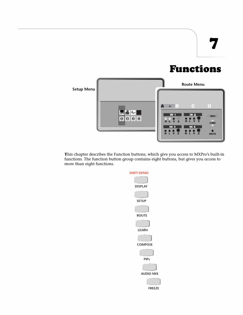
7
Functions
T
his chapter describes the Function buttons, which give you access to MXPro’s built-in functions. The function button group contains eight buttons, but gives you access to more than eight functions.
MUTE
Route MenuSetup Menu
DISPLAY
SHIFT-DEMO
SETUP
ROUTE
LEARN
COMPOSE
PIPs
AUDIO MIX
FREEZE
72
Chapter 7 Videonics MX-Pro User Guide
D
EMO
Press
SHIFT+DEMO
to run a demonstration of several MXPro transitions and other effects. Demo works in conjunction with the CURRENT and NEXT sources. (If you have one source selected as CURRENT and NEXT, the Demo works with that source only.) The Demo shows many of the effects you can produce with MXPro.
The demo runs automatically and, upon reaching the end, starts over from the beginning.
Procedure
To run the demo:
1
Select the CURRENT and NEXT sources to use for input to the demo.
To use a single source (such as channel A), press
CUT/A
and
NEXT/A
. To use two different sources (such as channels A and B), press
CUT/A
to make it the CUR-RENT source, then press
NEXT/B
to make it the NEXT source.
2
Press
SHIFT+DEMO
(or,
SHIFT+DISPLAY
) to start the demo running.
3
To exit from the demo, press any key.
Tip
If you see a transition you like while the demo runs, immediately press any key to stop the Demo. When the Preview screen returns, the last transition run is highlighted in the Transi-tions Menu. Make note of the transition number then add it to your custom User Transitions
Menu. See “Changing User Transitions Menu” beginning on page 54.
Running a Locked Demo
You can run the demo in
locked
mode, which prevents it being stopped by pressing any key on the keyboard. This might be useful for running the demo in a kiosk, a trade show, or anyplace where someone might interrupt it.
Procedure
To run the demo in Locked mode:
1
Complete step 1 described above.
2
Press
LEARN+DISPLAY
to start the demo.
3
To exit from the locked demo, press
LEARN+DISPLAY
again.
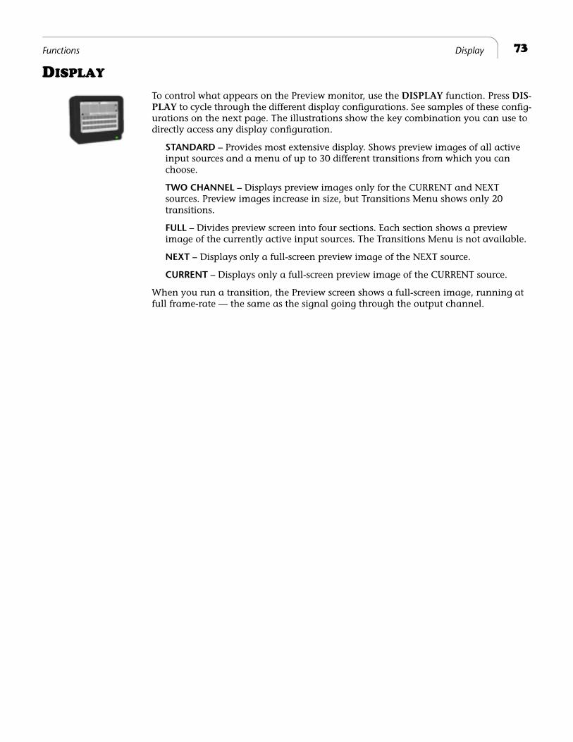
73
Functions Display
D
ISPLAY
To control what appears on the Preview monitor, use the
DISPLAY
function. Press
DIS-PLAY
to cycle through the different display configurations. See samples of these config-urations on the next page. The illustrations show the key combination you can use to directly access any display configuration.
STANDARD
–
Provides most extensive display. Shows preview images of all active input sources and a menu of up to 30 different transitions from which you can choose.
TWO CHANNEL
–
Displays preview images only for the CURRENT and NEXT sources. Preview images increase in size, but Transitions Menu shows only 20 transitions.
FULL
–
Divides preview screen into four sections. Each section shows a preview image of the currently active input sources. The Transitions Menu is not available.
NEXT
–
Displays only a full-screen preview image of the NEXT source.
CURRENT
–
Displays only a full-screen preview image of the CURRENT source.
When you run a transition, the Preview screen shows a full-screen image, running at full frame-rate — the same as the signal going through the output channel.

74
Chapter 7 Videonics MX-Pro User Guide
STANDARD – SHIFT+1
TWO CHANNEL – SHIFT+2 FULL – SHIFT+3
CURRENT – SHIFT+5NEXT – SHIFT+4
NoteFor all examples on this page, assume source A is CURRENT and source B is NEXT. Input sources C and D show up only when using STANDARD or FULL options.
Flashing white border indicates CURRENT source,unless that source is the COLOR channel.
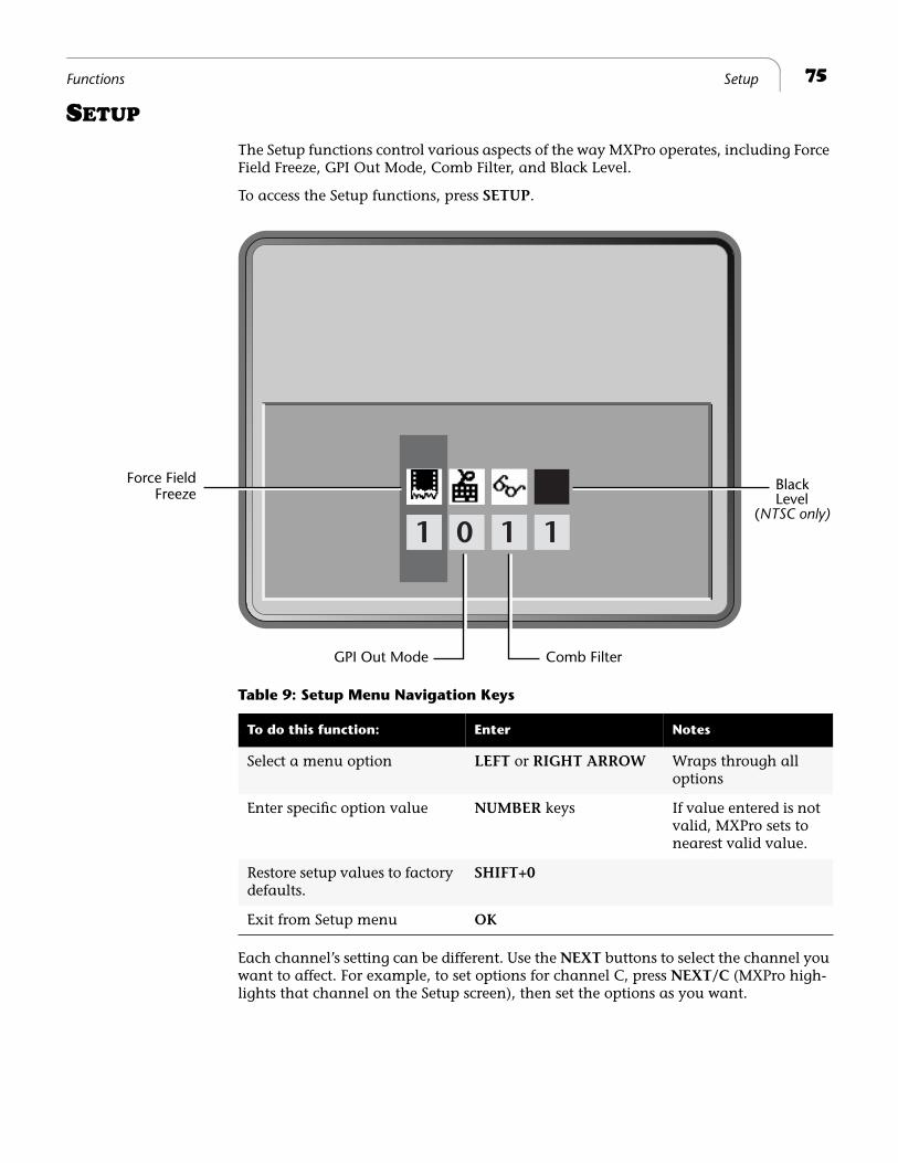
75
Functions Setup
S
ETUP
The Setup functions control various aspects of the way MXPro operates, including Force Field Freeze, GPI Out Mode, Comb Filter, and Black Level.
To access the Setup functions, press
SETUP
.
Each channel’s setting can be different. Use the
NEXT
buttons to select the channel you want to affect. For example, to set options for channel C, press
NEXT/C
(MXPro high-lights that channel on the Setup screen), then set the options as you want.
1 0 1 1
Force FieldFreeze
Black
GPI Out Mode Comb Filter
Level(NTSC only)
Table 9: Setup Menu Navigation Keys
To do this function: Enter Notes
Select a menu option
LEFT
or
RIGHT ARROW
Wraps through all options
Enter specific option value
NUMBER
keys If value entered is not valid, MXPro sets to nearest valid value.
Restore setup values to factory defaults.
SHIFT+0
Exit from Setup menu
OK
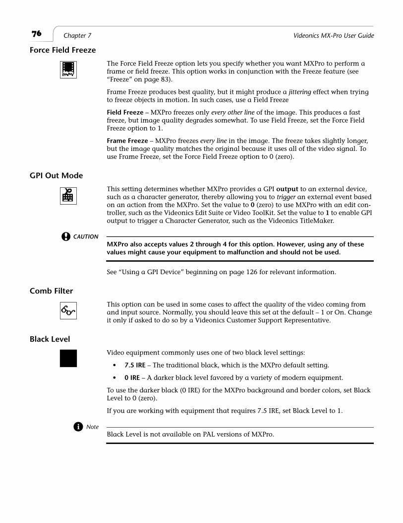
76
Chapter 7 Videonics MX-Pro User Guide
Force Field Freeze
The Force Field Freeze option lets you specify whether you want MXPro to perform a frame or field freeze. This option works in conjunction with the Freeze feature (see “Freeze” on page 83).
Frame Freeze produces best quality, but it might produce a
jittering
effect when trying to freeze objects in motion. In such cases, use a Field Freeze
Field Freeze
– MXPro freezes only
every other line
of the image. This produces a fast freeze, but image quality degrades somewhat. To use Field Freeze, set the Force Field Freeze option to 1.
Frame Freeze
– MXPro freezes
every line
in the image. The freeze takes slightly longer, but the image quality matches the original because it uses all of the video signal. To use Frame Freeze, set the Force Field Freeze option to 0 (zero).
GPI Out Mode
This setting determines whether MXPro provides a GPI
output
to an external device, such as a character generator, thereby allowing you to
trigger
an external event based on an action from the MXPro. Set the value to
0
(zero) to use MXPro with an edit con-troller, such as the Videonics Edit Suite or Video ToolKit. Set the value to
1
to enable GPI output to trigger a Character Generator, such as the Videonics TitleMaker.
CAUTION
MXPro also accepts values 2 through 4 for this option. However, using any of these
values might cause your equipment to malfunction and should not be used.
See “Using a GPI Device” beginning on page 126 for relevant information.
Comb Filter
This option can be used in some cases to affect the quality of the video coming from and input source. Normally, you should leave this set at the default – 1 or On. Change it only if asked to do so by a Videonics Customer Support Representative.
Black Level
Video equipment commonly uses one of two black level settings:
•
7.5 IRE
– The traditional black, which is the MXPro default setting.
•
0 IRE
– A darker black level favored by a variety of modern equipment.
To use the darker black (0 IRE) for the MXPro background and border colors, set Black Level to 0 (zero).
If you are working with equipment that requires 7.5 IRE, set Black Level to 1.
Note
Black Level is not available on PAL versions of MXPro.
77
Functions Route
R
OUTE
The Route function has the following, primary purposes:
• Configure MXPro to match your equipment.
• Re-direct signals coming from an input device to different or multiple MXPro channels.
• Split the audio input on IN 3.
Configuring MXPro
MXPro ships from the factory with the following default options:
• Source Input 1’s video and stereo audio are assigned to channel A, with the video signal routed through the S-Video connector.
• Source Input 2’s video and stereo audio are assigned to channel B, with the video signal routed through the S-Video connector.
• Source Input 3’s video and stereo audio are assigned to channel C, with the video signal routed through the S-Video connector.
The audio inputs for Input 3 have a special feature. You can split the audio to two different channels. Then use the Route function to indicate which connector (Left or Right) you used.
• Source Input 4’s video and stereo audio are assigned to channel D and the Back-ground Music channel, with the video signal routed through the S-Video connec-tor. The Background Music channel is permanently assigned to Audio Input 4 and cannot be changed. See Chapter 12,
Working with Audio
, for additional infor-mation.
Unless you tell MXPro otherwise, it assumes your sources are connected exactly as described above and shown in the following diagram.
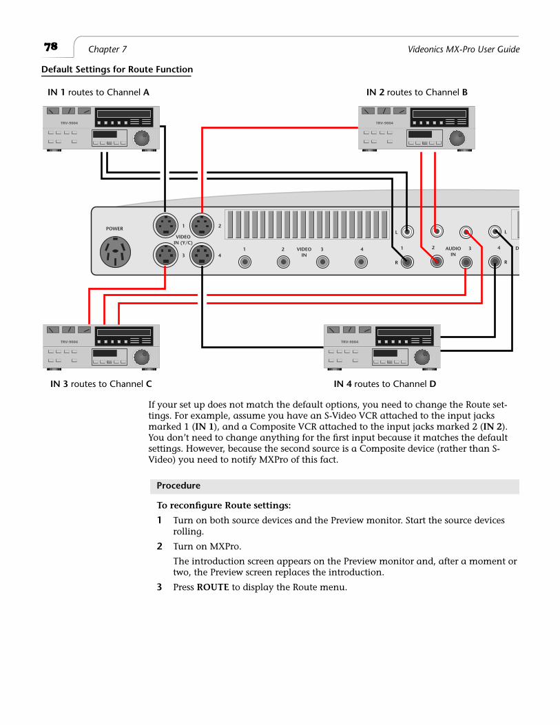
78
Chapter 7 Videonics MX-Pro User Guide
If your set up does not match the default options, you need to change the Route set-tings. For example, assume you have an S-Video VCR attached to the input jacks marked 1 (
IN 1
), and a Composite VCR attached to the input jacks marked 2 (
IN 2
). You don’t need to change anything for the first input because it matches the default settings. However, because the second source is a Composite device (rather than S-Video) you need to notify MXPro of this fact.
Procedure
To reconfigure Route settings:
1
Turn on both source devices and the Preview monitor. Start the source devices rolling.
2
Turn on MXPro.
The introduction screen appears on the Preview monitor and, after a moment or two, the Preview screen replaces the introduction.
3
Press
ROUTE
to display the Route menu.
IN 1 routes to Channel A
IN 3 routes to Channel C IN 4 routes to Channel D
IN 2 routes to Channel B
Default Settings for Route Function
VIDEOIN (Y/C)
VIDEOIN
POWER
AUDIOIN
DI
1 2
1 23 4
1
L
R
L
R
2 3 43 4
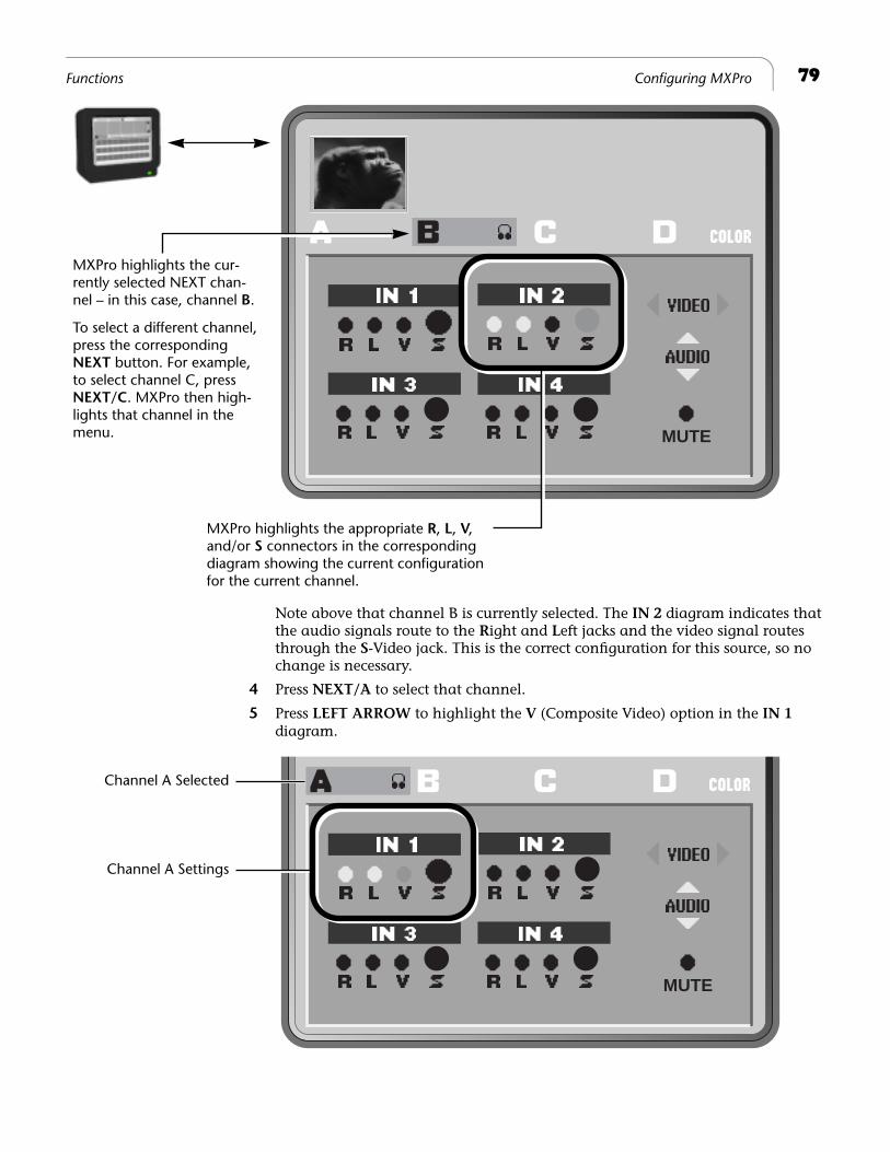
79
Functions Configuring MXPro
Note above that channel B is currently selected. The
IN 2
diagram indicates that the audio signals route to the
Right and Left jacks and the video signal routes through the S-Video jack. This is the correct configuration for this source, so no change is necessary.
4 Press NEXT/A to select that channel.
5 Press LEFT ARROW to highlight the V (Composite Video) option in the IN 1 diagram.
MUTE
MXPro highlights the cur-rently selected NEXT chan-nel – in this case, channel B.
To select a different channel, press the corresponding NEXT button. For example, to select channel C, press NEXT/C. MXPro then high-lights that channel in the menu.
MXPro highlights the appropriate R, L, V, and/or S connectors in the corresponding diagram showing the current configuration for the current channel.
MUTE
Channel A Selected
Channel A Settings
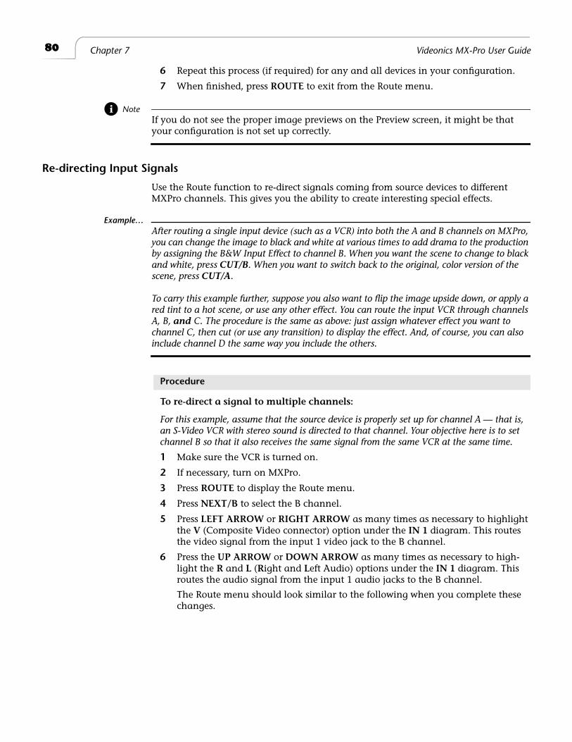
80 Chapter 7 Videonics MX-Pro User Guide
6 Repeat this process (if required) for any and all devices in your configuration.
7 When finished, press ROUTE to exit from the Route menu.
NoteIf you do not see the proper image previews on the Preview screen, it might be that your configuration is not set up correctly.
Re-directing Input Signals
Use the Route function to re-direct signals coming from source devices to different MXPro channels. This gives you the ability to create interesting special effects.
Example…After routing a single input device (such as a VCR) into both the A and B channels on MXPro, you can change the image to black and white at various times to add drama to the production by assigning the B&W Input Effect to channel B. When you want the scene to change to black and white, press CUT/B. When you want to switch back to the original, color version of the scene, press CUT/A.
To carry this example further, suppose you also want to flip the image upside down, or apply a red tint to a hot scene, or use any other effect. You can route the input VCR through channels A, B, and C. The procedure is the same as above: just assign whatever effect you want to channel C, then cut (or use any transition) to display the effect. And, of course, you can also include channel D the same way you include the others.
Procedure
To re-direct a signal to multiple channels:
For this example, assume that the source device is properly set up for channel A — that is, an S-Video VCR with stereo sound is directed to that channel. Your objective here is to set channel B so that it also receives the same signal from the same VCR at the same time.
1 Make sure the VCR is turned on.
2 If necessary, turn on MXPro.
3 Press ROUTE to display the Route menu.
4 Press NEXT/B to select the B channel.
5 Press LEFT ARROW or RIGHT ARROW as many times as necessary to highlight the V (Composite Video connector) option under the IN 1 diagram. This routes the video signal from the input 1 video jack to the B channel.
6 Press the UP ARROW or DOWN ARROW as many times as necessary to high-light the R and L (Right and Left Audio) options under the IN 1 diagram. This routes the audio signal from the input 1 audio jacks to the B channel.
The Route menu should look similar to the following when you complete these changes.
81Functions Routing Audio through Color Channel
You can now apply whatever effects you want to the B channel. For example, to flip the image horizontally, go to the Input Effects menu and activate the Flip effect for chan-nel B. During playback, alternately pressing CUT/A and CUT/B flips the image on the screen.
You can apply any of the other Input Effects to channel B, or to any channel for that matter.
Routing Audio through Color Channel
You can route an audio signal through the Color channel. This is useful, for example, if you want to fade to a solid color and would like to have a corresponding audio source.
Procedure
To route audio through the color channel:
1 Press NEXT/COLOR to select the color channel.
2 Make the proper settings for the appropriate IN options (1, 2, 3, or 4) for the audio source you want to use, the same way you select for the other channels.
Navigating the Route Menu
Use the LEFT and RIGHT ARROW keys to move the Video selector between the input diagrams – IN 1, IN 2, IN 3, and IN 4.
Use the UP and DOWN ARROW keys to move the Audio selector between the input diagrams. After cycling through all of the inputs, MXPro highlights the Mute option. With this option selected, MXPro mutes the audio for the selected channel.
MUTE
The Preview Image window for both the A and B channels should show the same source image.
The input signals (video and audio) connected to the MXPro inputs labeled 1 have now been directed through channel B.
82 Chapter 7 Videonics MX-Pro User Guide
LEARN
The Learn feature consists of one or more Learned Environments. Within each Learned Environment you can create a Learned Script.
In a Learned Script you teach MXPro about a series of transitions and edits you want to include in a production. This is similar to using an Edit Decision List (EDL), though not as flexible or powerful.
Once you activate the Learn feature, MXPro remembers each step you go through in preparing a production — including all transitions, input effects, and other operations. Thereafter, you can play back this Learned Script to automatically perform all of the steps and functions it contains.
See Chapter 11, Learn Mode, for further information.
COMPOSE
Use Compose to create screen images made up of several different graphic elements. For example, a composed screen might show two still images (polar bears in passion-ate embrace and Kong contemplating the meaning of the universe) placed atop solid colored rectangles and a solid colored background. With a character generator (or, titlemaker), you can also add text elements to composed screens and use the screen as subtitles or whatever need you might have. See Chapter 9, Compose.
PIPS
PIPs (Picture-In-Picture) let you combine images from separate sources and place them on the screen at the same time in separate windows (or, tiles). You have many options for arranging the PIP windows on the screen. See Chapter 8, PIPs.
AUDIO MIX
Use Audio Mix to adjust audio levels for any channel. See Chapter 12, Working with Audio.
MXPro
LearnedScript
MIXCOLOR+6
+3
0
-3
-6
-10
-20
-30
-°
83Functions Freeze
FREEZE
The Freeze effect immediately freezes the selected video source. You can freeze up to two video sources, then transition between them while retaining the freeze – that is, the freeze stays in MXPro’s memory until you specifically release it.
This section describes the types of freeze effects you can produce with MXPro and how to use Freeze with transitions.
You can also use the Freeze effect with the MXPro PIP and Compose features. Refer to Chapter 8, PIPs, and Chapter 9, Compose, for further information.
Field and Frame Freezes
You can freeze either a video Field, or a full Frame.
Field Freeze – Captures every other horizontal line of the video. This is ideal for cap-turing anything in motion.
Frame Freeze – Captures all horizontal lines, thereby producing a higher resolution (better quality) image. Use Frame Freeze when working with still images, such as photographs. Using Frame Freeze with images in motion normally produces jitter in the movie.
MXPro captures using Field Freeze, by default. See “Force Field Freeze” on page 76 to learn how to change the default setting.
Major Freeze Functions
MXPro provides three major freeze functions: Freeze Current, Freeze Next, and Freeze During (Transitions).
Freeze Current Freezes the image on the Program Output device.
¨ To freeze the video on the current source, press FREEZE.
¨ To unfreeze the video on the current source, press FREEZE again, or press the CUT button that corresponds to the current source.
Freeze Next Freezes the video on the Next source. This is useful for freezing an image, then transi-tioning to it.
Procedure
To use the Freeze Next function:
1 Enter SHIFT+4 to set your Preview monitor to Preview Next mode.
2 To freeze the video on the Next source, enter SHIFT+FREEZE.
3 To unfreeze the video on the Next source, do one of the following:
Enter SHIFT+FREEZE, again.
Press the NEXT button that corresponds to the Next source – that is, the one below the flashing LED indicator near the top of the keyboard.
4 To unfreeze the Next source in Preview modes other than Preview Next, press any of the NEXT buttons – A, B, C, D, or COLOR.
Freeze During(Transition)
Stops the current transition and freezes both the Current and Next video sources.
¨ To restart the transition and unfreeze the Current and Next sources, press FREEZE or PLAY.
84 Chapter 7 Videonics MX-Pro User Guide
Freeze Examples
This section discusses some common uses for the Freeze function. As you use MXPro over time, you’ll probably create many others ways to use this function.
Single Source (A/A)Editing
When working with a single source, use the Freeze function to transition to or from the second image.
Procedure
To use Freeze with Single Source Editing:
1 Route a video source to Channel A.
2 Use the CUT/A and NEXT/A buttons to specify source A as both the Current and Next source.
3 Press FREEZE to freeze the Current source.
MXPro freezes the Current source on the Program monitor, and the Next source (on the Preview monitor) continues moving even though there is only one source.
4 Enter 1+PLAY to run a simple dissolve transition. The frozen image dissolves to moving video.
5 Press NEXT/A to release the freeze on the Next source.
If you want, repeat steps 3 through 5 to freeze and dissolve back and forth.
The following steps explain how to transition from moving video to a still image.
6 Enter SHIFT+4 to select Preview Next mode on the Preview monitor.
7 Enter SHIFT+FREEZE to create a still frame on the Next source.
8 Enter 1+PLAY to dissolve from the Current moving video to the Next still image.
9 Press FREEZE to release the freeze on the Current source.
85Functions Freeze Examples
Creating Still Montages You can use the Freeze function to transition between a series of still images to create a “still montage.” You can use anywhere from one to four sources.
Procedure
To create a still montage:
1 Route at least one video source to Channel A. Remember, you can use up to as many as four sources for this procedure.
This example starts from a black screen, then transitions to a still image.
2 Enter BG COLOR+0 (zero) to set the background color to black.
3 Press CUT/COLOR to set the Color Channel as the Current source. You now have a black screen on the Program monitor.
4 Press NEXT/A to set Channel A as the Next source.
5 Enter SHIFT+4 to set the Preview monitor to Preview Next mode.
You’re now ready to create and transition to the first still image.
6 Enter SHIFT+FREEZE to create a frozen image on the Next channel.
7 Enter 1+PLAY to dissolve from black to the first frozen image.
The Next and Current sources swap positions. You’re now ready to select the sec-ond still image.
8 Press any NEXT button to release the freeze on the Next source and select a new source to freeze.
9 Enter SHIFT+FREEZE to freeze the Next image.
10 Enter 1+PLAY to dissolve to the Next image.
To transition to other still images, repeat steps 8 through 10.
86 Chapter 7 Videonics MX-Pro User Guide
Freeze and Transitions
The preceding examples used the dissolve transition to move between frozen images. You can use any MXPro transition to move between freezes, with the following excep-tions:
• MXPro cannot perform a Trailing-type transition TO a frozen image. It releases the Next source prior to running the transition.
• MXPro can perform a Trailing-type transition FROM a frozen source to a moving source. However, it loses the freeze once the transition finishes.
• MXPro cannot compress frozen images. If you select a compression effect, MXPro automatically runs the selected effect without compressing the video; resulting in a wipe transition.
• To hold frame freezes, press SHIFT+4 (to set the Preview monitor to Preview Next mode) or SHIFT+5 (to set to Preview Current mode). In any other Preview mode, a Frame freeze reverts to a Field freeze once the transition begins to run.
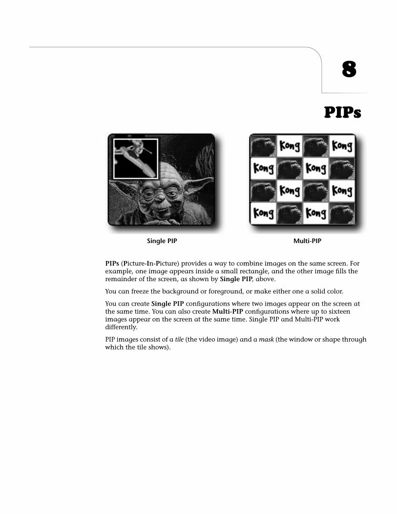
8
PIPs
PIPs
(
P
icture-
I
n-
P
icture) provides a way to combine images on the same screen. For example, one image appears inside a small rectangle, and the other image fills the remainder of the screen, as shown by
Single PIP
, above.
You can freeze the background or foreground, or make either one a solid color.
You can create
Single PIP
configurations where two images appear on the screen at the same time. You can also create
Multi-PIP
configurations where up to sixteen images appear on the screen at the same time. Single PIP and Multi-PIP work differently.
PIP images consist of a
tile
(the video image) and a
mask
(the window or shape through which the tile shows).
Multi-PIPSingle PIP
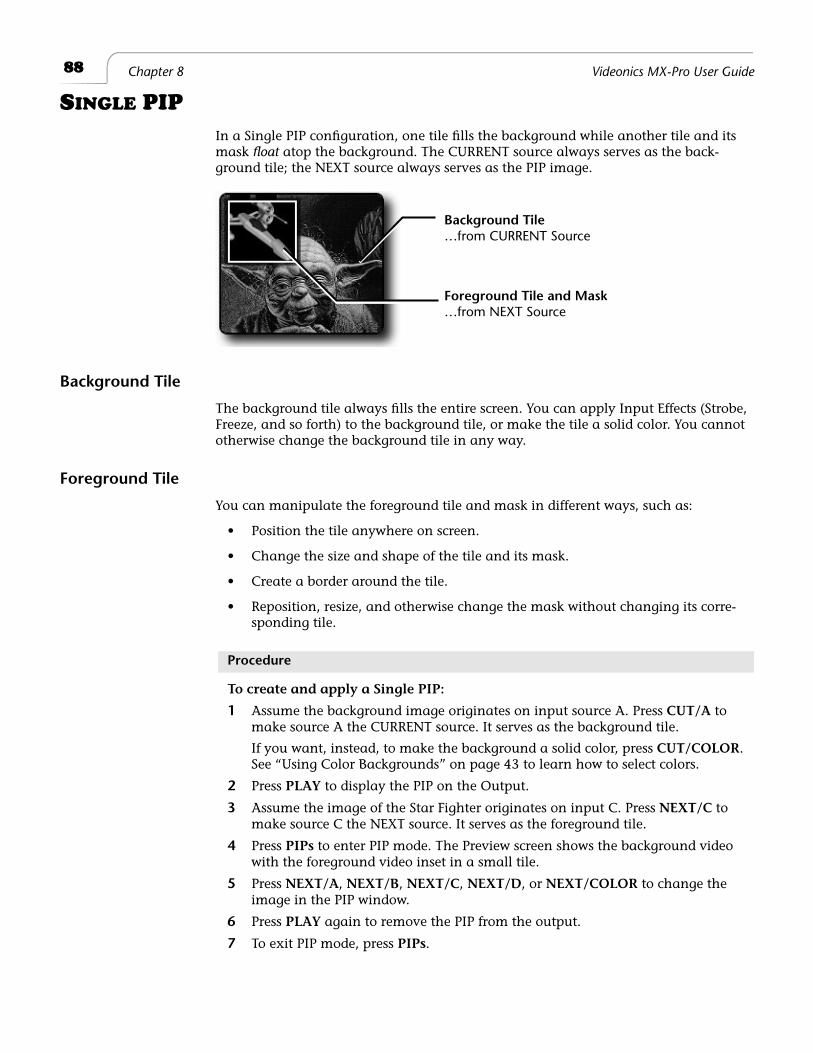
88
Chapter 8 Videonics MX-Pro User Guide
S
INGLE
PIP
In a Single PIP configuration, one tile fills the background while another tile and its mask
float
atop the background. The CURRENT source always serves as the back-ground tile; the NEXT source always serves as the PIP image.
Background Tile
The background tile always fills the entire screen. You can apply Input Effects (Strobe, Freeze, and so forth) to the background tile, or make the tile a solid color. You cannot otherwise change the background tile in any way.
Foreground Tile
You can manipulate the foreground tile and mask in different ways, such as:
• Position the tile anywhere on screen.
• Change the size and shape of the tile and its mask.
• Create a border around the tile.
• Reposition, resize, and otherwise change the mask without changing its corre-sponding tile.
Procedure
To create and apply a Single PIP:
1
Assume the background image originates on input source A. Press
CUT/A
to make source A the CURRENT source. It serves as the background tile.
If you want, instead, to make the background a solid color, press
CUT/COLOR
. See “Using Color Backgrounds” on page 43
to learn how to select colors.
2
Press
PLAY
to display the PIP on the Output.
3
Assume the image of the Star Fighter originates on input C. Press
NEXT/C
to make source C the NEXT source. It serves as the foreground tile.
4
Press
PIPs
to enter PIP mode. The Preview screen shows the background video with the foreground video inset in a small tile.
5
Press
NEXT/A
,
NEXT/B
,
NEXT/C
,
NEXT/D
, or
NEXT/COLOR
to change the image in the PIP window.
6
Press
PLAY
again to remove the PIP from the output.
7
To exit PIP mode, press
PIPs
.
Background Tile
Foreground Tile and Mask…from NEXT Source
…from CURRENT Source
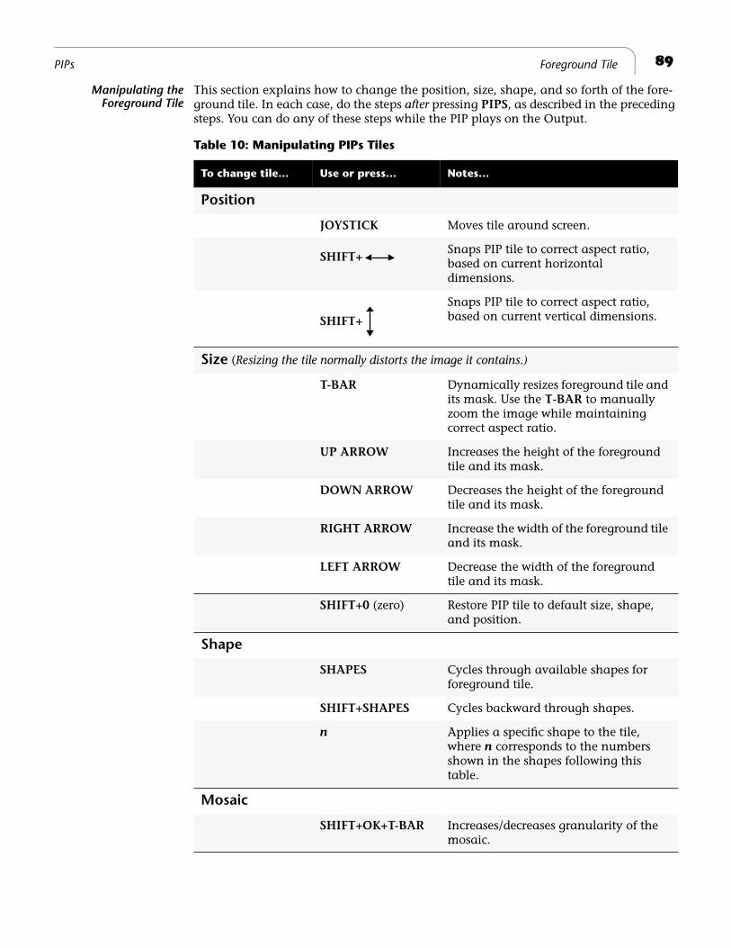
89
PIPs Foreground Tile
Manipulating theForeground Tile
This section explains how to change the position, size, shape, and so forth of the fore-ground tile. In each case, do the steps
after
pressing
PIPS
, as described in the preceding steps. You can do any of these steps while the PIP plays on the Output.
Table 10: Manipulating PIPs Tiles
To change tile… Use or press… Notes…
Position
JOYSTICK
Moves tile around screen.
SHIFT+
Snaps PIP tile to correct aspect ratio, based on current horizontal dimensions.
SHIFT+
Snaps PIP tile to correct aspect ratio, based on current vertical dimensions.
Size
(
Resizing the tile normally distorts the image it contains.)
T-BAR
Dynamically resizes foreground tile and its mask. Use the
T-BAR
to manually zoom the image while maintaining correct aspect ratio.
UP ARROW
Increases the height of the foreground tile and its mask.
DOWN ARROW
Decreases the height of the foreground tile and its mask.
RIGHT ARROW
Increase the width of the foreground tile and its mask.
LEFT ARROW
Decrease the width of the foreground tile and its mask.
SHIFT+0
(zero) Restore PIP tile to default size, shape, and position.
Shape
SHAPES
Cycles through available shapes for foreground tile.
SHIFT+SHAPES
Cycles backward through shapes.
n
Applies a specific shape to the tile, where
n
corresponds to the numbers shown in the shapes following this table.
Mosaic
SHIFT+OK+T-BAR
Increases/decreases granularity of the mosaic.
90
Chapter 8 Videonics MX-Pro User Guide
You can apply the following shapes to PIP tiles.
To select a shape, press the numeric key (0 through 9) that corresponds to the shape you want, as indicated below.
Manipulating the Mask
The mask changes shape, size, and position when you change the corresponding attribute of the foreground tile. You can, however, manipulate the mask indepen-dently, as described in this section.
Using Other Effects with Single PIPs
Input Effects
You can apply any of the input effects (see Chapter 6,
Input Effects
) to the background and/or foreground tile. Apply the input effect(s) you want prior to entering PIP mode.
The Freeze Effect
You can apply the Freeze effect (see “Freeze” on page 83) to the background and/or foreground tile.
Press
FREEZE
while in PIPs mode to freeze the background. Press
FREEZE
again to release the freeze effect.
Press
SHIFT+FREEZE
while in PIPs mode to freeze the foreground tile. Press
SHIFT+FREEZE
again to release the freeze effect.
When you exit PIPs mode, MXPro removes the freeze effect from the foreground source.
0 2 3 4
5 6 7 98
1
Table 11: Manipulating PIPs Mask
To change mask…
Use or press… Notes…
Position
SHIFT+JOYSTICK
Change mask position.
Style
(Press keys repeatedly to cycle through available colors and styles.)
BORDER COLOR
Change mask border color.
BORDER STYLE
Change mask border style.
Size
SHIFT+T-BAR
Change mask size.
SHIFT+UP ARROW
Increase vertical size of mask.
SHIFT+DOWN ARROW
Decrease vertical size of mask.
SHIFT+RIGHT ARROW
Increase horizontal size of mask.
SHIFT+LEFT ARROW
Decrease horizontal size of mask.
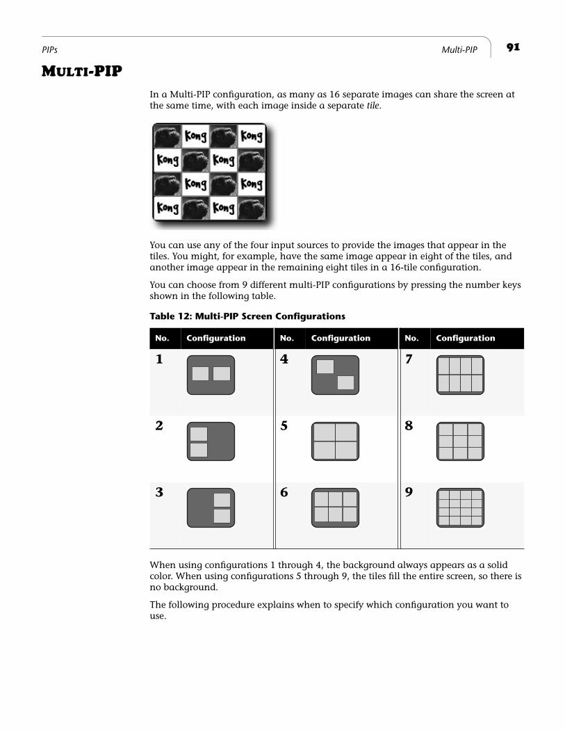
91
PIPs Multi-PIP
M
ULTI
-PIP
In a Multi-PIP configuration, as many as 16 separate images can share the screen at the same time, with each image inside a separate
tile
.
You can use any of the four input sources to provide the images that appear in the tiles. You might, for example, have the same image appear in eight of the tiles, and another image appear in the remaining eight tiles in a 16-tile configuration.
You can choose from 9 different multi-PIP configurations by pressing the number keys shown in the following table.
When using configurations 1 through 4, the background always appears as a solid color. When using configurations 5 through 9, the tiles fill the entire screen, so there is no background.
The following procedure explains when to specify which configuration you want to use.
Table 12: Multi-PIP Screen Configurations
No. Configuration No. Configuration No. Configuration
1 4 7
2 5 8
3 6 9
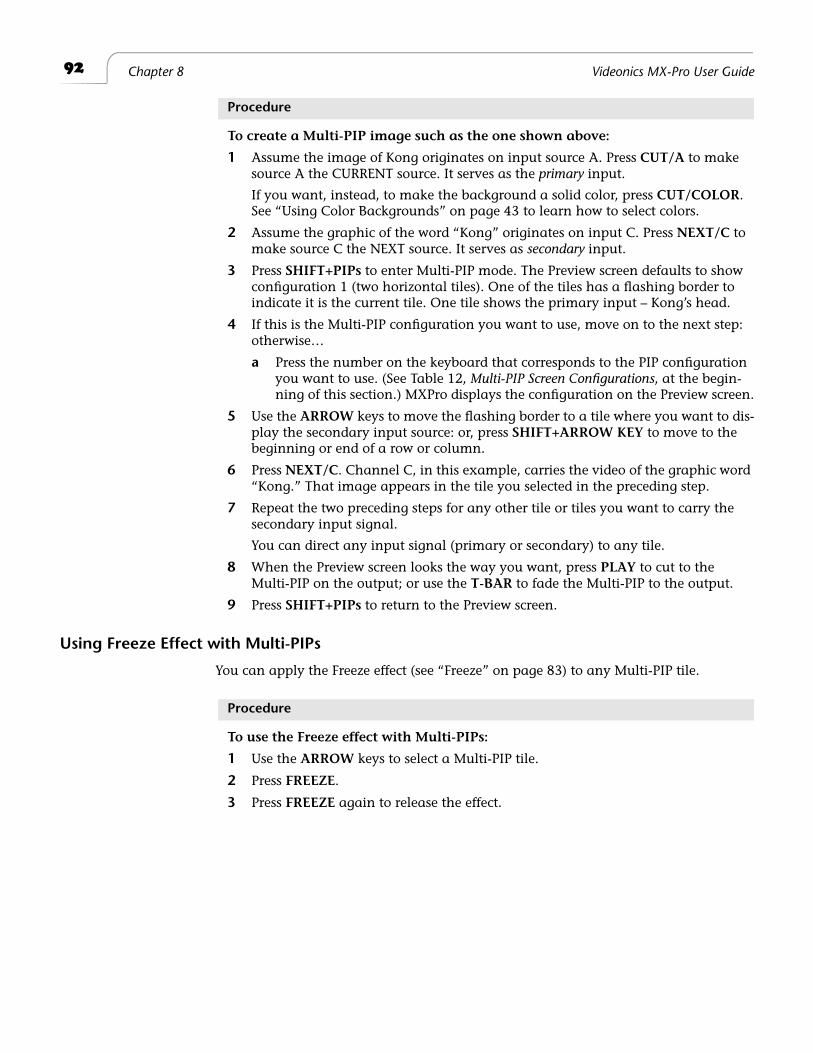
92
Chapter 8 Videonics MX-Pro User Guide
Procedure
To create a Multi-PIP image such as the one shown above:
1 Assume the image of Kong originates on input source A. Press CUT/A to make source A the CURRENT source. It serves as the primary input.
If you want, instead, to make the background a solid color, press CUT/COLOR. See “Using Color Backgrounds” on page 43 to learn how to select colors.
2 Assume the graphic of the word “Kong” originates on input C. Press NEXT/C to make source C the NEXT source. It serves as secondary input.
3 Press SHIFT+PIPs to enter Multi-PIP mode. The Preview screen defaults to show configuration 1 (two horizontal tiles). One of the tiles has a flashing border to indicate it is the current tile. One tile shows the primary input – Kong’s head.
4 If this is the Multi-PIP configuration you want to use, move on to the next step: otherwise…
a Press the number on the keyboard that corresponds to the PIP configuration you want to use. (See Table 12, Multi-PIP Screen Configurations, at the begin-ning of this section.) MXPro displays the configuration on the Preview screen.
5 Use the ARROW keys to move the flashing border to a tile where you want to dis-play the secondary input source: or, press SHIFT+ARROW KEY to move to the beginning or end of a row or column.
6 Press NEXT/C. Channel C, in this example, carries the video of the graphic word “Kong.” That image appears in the tile you selected in the preceding step.
7 Repeat the two preceding steps for any other tile or tiles you want to carry the secondary input signal.
You can direct any input signal (primary or secondary) to any tile.
8 When the Preview screen looks the way you want, press PLAY to cut to the Multi-PIP on the output; or use the T-BAR to fade the Multi-PIP to the output.
9 Press SHIFT+PIPs to return to the Preview screen.
Using Freeze Effect with Multi-PIPs
You can apply the Freeze effect (see “Freeze” on page 83) to any Multi-PIP tile.
Procedure
To use the Freeze effect with Multi-PIPs:
1 Use the ARROW keys to select a Multi-PIP tile.
2 Press FREEZE.
3 Press FREEZE again to release the effect.
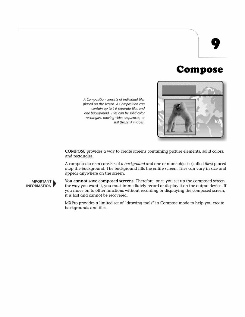
9
Compose
COMPOSE
provides a way to create screens containing picture elements, solid colors, and rectangles.
A composed screen consists of a
background
and one or more objects (called
tiles
) placed atop the background. The background fills the entire screen. Tiles can vary in size and appear anywhere on the screen.
You cannot save composed screens
. Therefore, once you set up the composed screen the way you want it, you must immediately record or display it on the output device. If you move on to other functions without recording or displaying the composed screen, it is lost and cannot be recovered.
MXPro provides a limited set of “drawing tools” in Compose mode to help you create backgrounds and tiles.
A Composition consists of individual tilesplaced on the screen. A Composition can
contain up to 16 separate tiles andone background. Tiles can be solid colorrectangles, moving video sequences, or
still (frozen) images.
IMPORTANTINFORMATION
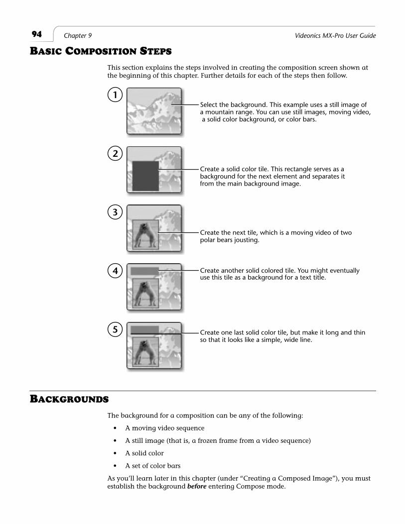
94
Chapter 9 Videonics MX-Pro User Guide
B
ASIC
C
OMPOSITION
S
TEPS
This section explains the steps involved in creating the composition screen shown at the beginning of this chapter. Further details for each of the steps then follow.
B
ACKGROUNDS
The background for a composition can be any of the following:
• A moving video sequence
• A still image (that is, a frozen frame from a video sequence)
• A solid color
• A set of color bars
As you’ll learn later in this chapter (under “Creating a Composed Image”), you must establish the background
before
entering Compose mode.
1
2
3
4
5
Select the background. This example uses a still image ofa mountain range. You can use still images, moving video, a solid color background, or color bars.
Create a solid color tile. This rectangle serves as a background for the next element and separates itfrom the main background image.
Create the next tile, which is a moving video of twopolar bears jousting.
Create another solid colored tile. You might eventually
Create one last solid color tile, but make it long and thinso that it looks like a simple, wide line.
use this tile as a background for a text title.
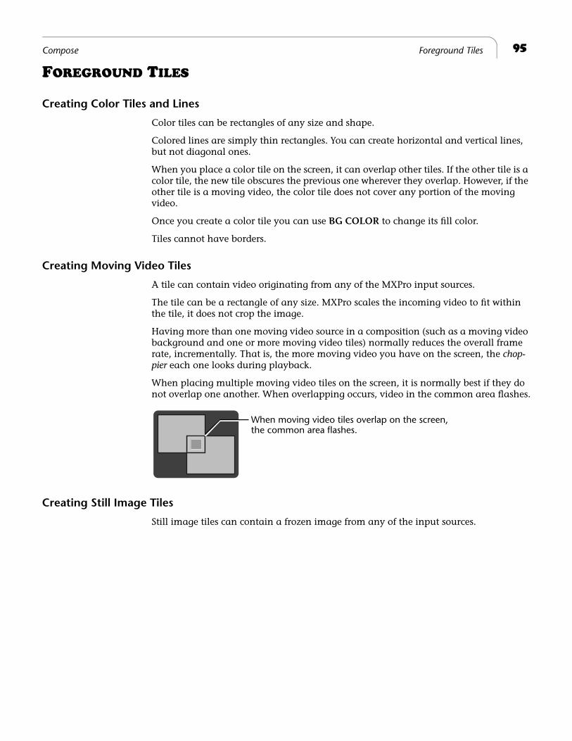
95
Compose Foreground Tiles
F
OREGROUND
T
ILES
Creating Color Tiles and Lines
Color tiles can be rectangles of any size and shape.
Colored lines are simply thin rectangles. You can create horizontal and vertical lines, but not diagonal ones.
When you place a color tile on the screen, it can overlap other tiles. If the other tile is a color tile, the new tile obscures the previous one wherever they overlap. However, if the other tile is a moving video, the color tile does not cover any portion of the moving video.
Once you create a color tile you can use
BG COLOR
to change its fill color.
Tiles cannot have borders.
Creating Moving Video Tiles
A tile can contain video originating from any of the MXPro input sources.
The tile can be a rectangle of any size. MXPro scales the incoming video to fit within the tile, it does not crop the image.
Having more than one moving video source in a composition (such as a moving video background and one or more moving video tiles) normally reduces the overall frame rate, incrementally. That is, the more moving video you have on the screen, the
chop-pier
each one looks during playback.
When placing multiple moving video tiles on the screen, it is normally best if they do not overlap one another. When overlapping occurs, video in the common area flashes.
Creating Still Image Tiles
Still image tiles can contain a frozen image from any of the input sources.
When moving video tiles overlap on the screen,the common area flashes.
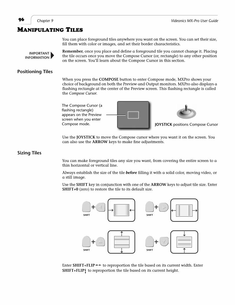
96
Chapter 9 Videonics MX-Pro User Guide
M
ANIPULATING
T
ILES
You can place foreground tiles anywhere you want on the screen. You can set their size, fill them with color or images, and set their border characteristics.
Remember
, once you place and define a foreground tile you cannot change it. Placing the tile occurs once you move the Compose Cursor (or, rectangle) to any other position on the screen. You’ll learn about the Compose Cursor in this section.
Positioning Tiles
When you press the
COMPOSE
button to enter Compose mode, MXPro shows your choice of background on both the Preview and Output monitors. MXPro also displays a flashing rectangle at the center of the Preview screen. This flashing rectangle is called the
Compose Cursor
.
Use the
JOYSTICK
to move the Compose cursor where you want it on the screen. You can also use the
ARROW
keys to make fine adjustments.
Sizing Tiles
You can make foreground tiles any size you want, from covering the entire screen to a thin horizontal or vertical line.
Always establish the size of the tile
before
filling it with a solid color, moving video, or a still image.
Use the
SHIFT
key in conjunction with one of the
ARROW
keys to adjust tile size. Enter
SHIFT+0
(zero) to restore the tile to its default size.
Enter
SHIFT+FLIP
to reproportion the tile based on its current width. Enter
SHIFT+FLIP
to reproportion the tile based on its current height.
IMPORTANTINFORMATION
JOYSTICK positions Compose Cursor
The Compose Cursor (a flashing rectangle) appears on the Preview screen when you enter Compose mode.
SHIFT SHIFT
SHIFT SHIFT
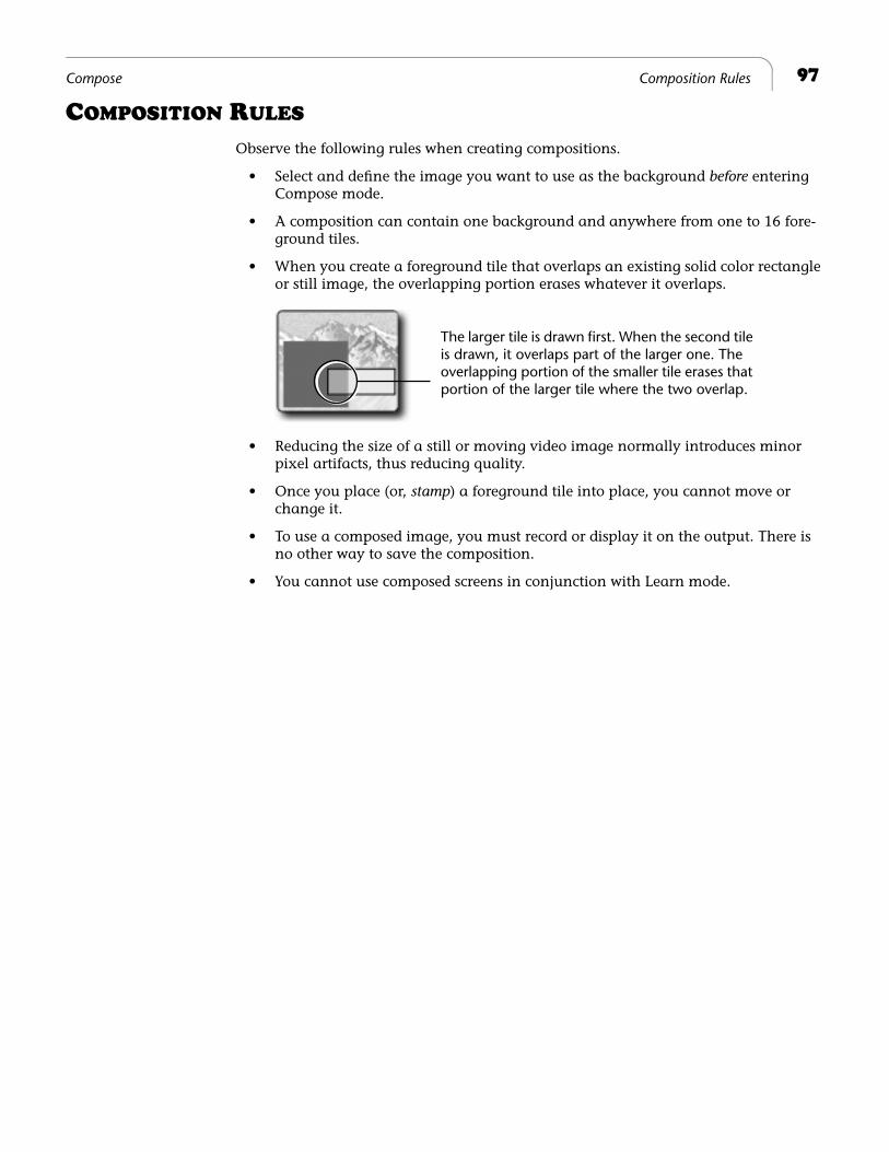
97
Compose Composition Rules
C
OMPOSITION
R
ULES
Observe the following rules when creating compositions.
• Select and define the image you want to use as the background
before
entering Compose mode.
• A composition can contain one background and anywhere from one to 16 fore-ground tiles.
• When you create a foreground tile that overlaps an existing solid color rectangle or still image, the overlapping portion erases whatever it overlaps.
• Reducing the size of a still or moving video image normally introduces minor pixel artifacts, thus reducing quality.
• Once you place (or,
stamp
) a foreground tile into place, you cannot move or change it.
• To use a composed image, you must record or display it on the output. There is no other way to save the composition.
• You cannot use composed screens in conjunction with Learn mode.
The larger tile is drawn first. When the second tile is drawn, it overlaps part of the larger one. The overlapping portion of the smaller tile erases that portion of the larger tile where the two overlap.
98
Chapter 9 Videonics MX-Pro User Guide
C
REATING
A
C
OMPOSED
I
MAGE
Procedure
To create a composition:
1
Create or choose the background on the Preview screen. Do this
before
entering Compose mode because the CURRENT source at the time you enter Compose mode automatically becomes the background for the composition.
a
Solid Color Background
– Use the
BG COLOR
button to select the color you want. Then press
CUT/COLOR
or use a transition to make COLOR the CUR-RENT source.
b
Moving Video Sequence
– Use the appropriate
CUT
button to make the desired input source the CURRENT one. For example, to use a moving video sequence from source C as the background, press
CUT/C
.
c
Still Image
– Use the appropriate
CUT
button to make the desired input source the CURRENT one. For example, to use a frame from source B as the background, press
CUT/B
. When the frame you want to use as the still image appears on the Preview screen, press
FREEZE
to create the still image.
d
Color Bars
– Press
SHIFT+NEXT COLOR
while in Compose mode to display color bars in the background.
e
Input Effects
– Apply any Input Effects you want to use before entering Com-pose mode.
2
Press
COMPOSE
to enter Compose mode.
A full screen image of the CURRENT source (the one on the Output) replaces the Preview screen. The Compose Cursor appears on the Preview screen.
Tip
To use color bars as the background, enter
SHIFT+NEXT COLOR
now
– before
creating fore-
ground tiles.
99
Compose Playing the Composition
3
Use the
JOYSTICK
or
ARROW KEYS
to position the Compose Cursor where you want it on the screen.
4
Size the Compose Cursor to the size you want for the foreground tile.
You can do the two preceding steps in either order.
5
Press one of the
NEXT
buttons to fill the tile with whatever color or image you want.
a Solid Color Background – Press NEXT/COLOR to fill the tile with the cur-rently selected color.
To specify a different color from the one currently selected, press BG COLOR until the color you want fills the tile.
To create a custom color for the tile, press LEARN+BG COLOR, then use the JOYSTICK and T-BAR to create a new color. Press OK when the tile color is the one you want.
b Moving Video Sequence – Press the appropriate NEXT button to select source A, B, C, or D. If the dimensions of the tile and video do not match, the video appears distorted.
c Frozen Image – Fill the moving video tile with the image you want, then press FREEZE.
6 Repeat steps 3 through 5 until your composition is complete.
7 Use the PLAY button or T-BAR to send your composition to the Program.
PLAYING THE COMPOSITION
Procedure
To play a composition on the output device:
¨ Press PLAY or use the T-BAR.
Moving the T-BAR from the top-to-bottom in its slot transitions the composition to Program. Moving it from bottom-to-top dissolves out.
Pressing PLAY produces a cut from the CURRENT source to the composed screen — using the T-BAR produces a dissolve. Pressing PLAY or using the T-BAR again lets you switch back and forth between the CURRENT source and the composed image.
NoteIf you cut to any source or exit from Compose mode, your composed screen will be lost and cannot be recovered.

100 Chapter 9 Videonics MX-Pro User Guide
EXITING FROM COMPOSE MODE
Remember, if you do not record your composed image to the output device before exit-ing Compose mode, your composed image will be lost and cannot be recovered.
To exit from Compose mode, press COMPOSE.
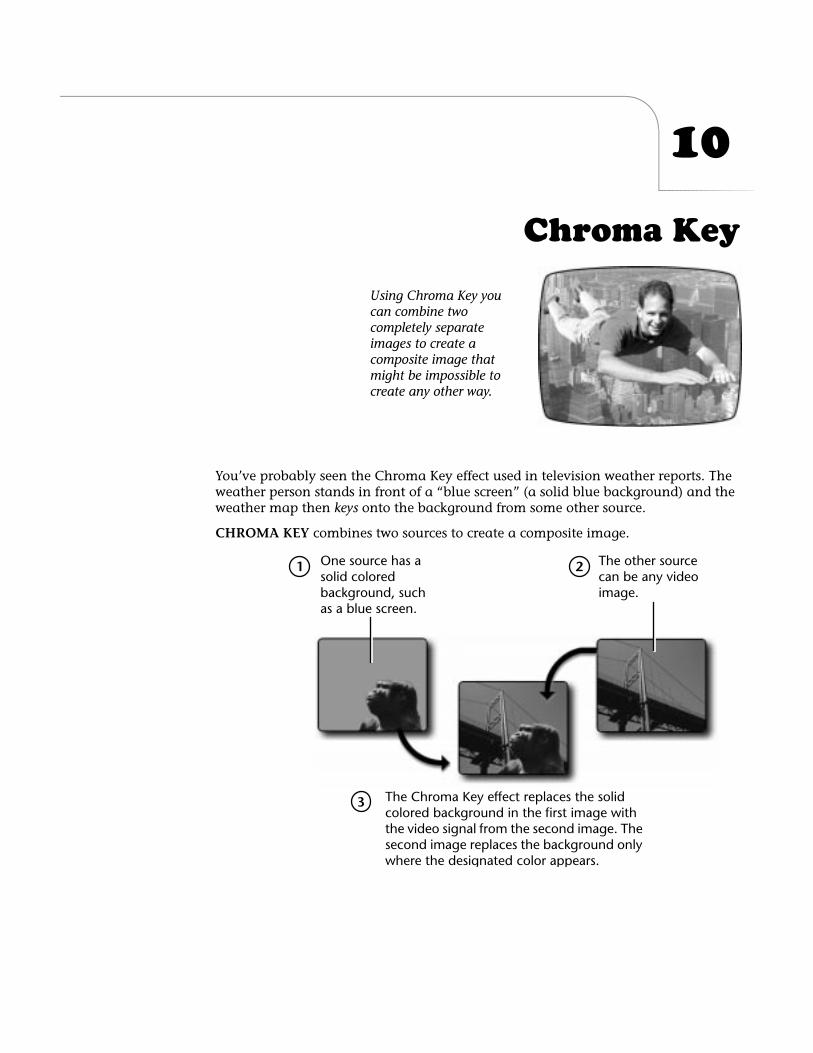
10
Chroma Key
You’ve probably seen the Chroma Key effect used in television weather reports. The weather person stands in front of a “blue screen” (a solid blue background) and the weather map then
keys
onto the background from some other source.
CHROMA KEY
combines two sources to create a composite image.
Using Chroma Key you can combine two completely separate images to create a composite image that might be impossible to create any other way.
One source has a solid colored background, such as a blue screen.
The other source can be any video image.
The Chroma Key effect replaces the solid colored background in the first image with the video signal from the second image. The second image replaces the background only where the designated color appears.
1 2
3
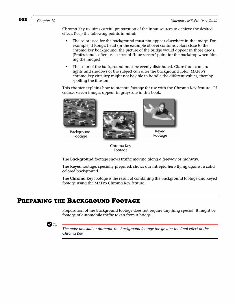
102
Chapter 10 Videonics MX-Pro User Guide
Chroma Key requires careful preparation of the input sources to achieve the desired effect. Keep the following points in mind:
• The color used for the background must not appear elsewhere in the image. For example, if Kong’s head (in the example above) contains colors close to the chroma key background, the picture of the bridge would appear in those areas. (Professionals often use a special “blue screen” paint for the backdrop when film-ing the image.)
• The color of the background must be evenly distributed. Glare from camera lights and shadows of the subject can alter the background color. MXPro’s chroma key circuitry might not be able to handle the different values, thereby spoiling the illusion.
This chapter explains how to prepare footage for use with the Chroma Key feature. Of course, screen images appear in grayscale in this book.
The
Background
footage shows traffic moving along a freeway or highway.
The
Keyed
footage, specially prepared, shows our intrepid hero flying against a solid colored background.
The
Chroma Key
footage is the result of combining the Background footage and Keyed footage using the MXPro Chroma Key feature.
P
REPARING
THE
B
ACKGROUND
F
OOTAGE
Preparation of the Background footage does not require anything special. It might be footage of automobile traffic taken from a bridge.
Tip
The more unusual or dramatic the Background footage the greater the final effect of the
Chroma Key.
BackgroundFootage
KeyedFootage
Chroma KeyFootage
103
Chroma Key Preparing the Keyed Footage
P
REPARING
THE
K
EYED
F
OOTAGE
Preparation of the Keyed footage presents a challenge. It is the most important and most difficult step, because the solid colored background is so crucial to the success of the illusion. To achieve the required background requires, in most cases, special props, lighting, and other materials.
In this example, we placed our flying hero atop a platform centered on the set.
Here’s how the footage used in this example was prepared:
• Uniquely colored fabric was draped over the back, sides, and bottom of the set. The same fabric was used to wrap completely around the platform on which we posed our flying hero.
When choosing the fabric color, it was important to try and select a fabric that did not contain any of the colors in our flying hero’s wardrobe. A professional studio would most likely use a blue screen in place of the colored fabric. Blue screen paint is a very unique color that minimizes (though might not eliminate) glaring and shadowing.
• Key lights and fill lights were positioned so as to minimize glare and shadows during filming.
Light bouncing off an area produces different shades of the background color. Likewise, shadows also produce varying shades. The key to successful Chroma Keys is to reduce as much as possible the colors in the background.
The use of lighting filters, umbrellas, lighting stands, and similar tools can make a tremendous difference in the quality of the Chroma Key as well as the amount of “post production” work you must do to produce the exact illusion you want.
• Several test shots were made, then lighting was adjusted, the actor was reposi-tioned, and so forth, until the optimum results were produced.
• Final footage was then shot.
P
REPARING
THE
C
HROMA
K
EY
F
OOTAGE
With the Background footage and Keyed footage recorded and available, you’re ready to combine them into the Chroma Key effect. The following steps assume that source A is the Background footage (the traffic sequence) and source C is the Keyed footage (the flying hero).
Procedure
To prepare the Chroma Key footage:
1
If necessary, turn on MXPro and all sources.
2
Start both sources (A and C) rolling.
3
Select the Background footage as the CURRENT source — that is, press
CUT/A
. The image appears on the Program monitor.
4
Select the Keyed footage as the NEXT source — that is, press
NEXT/C
.
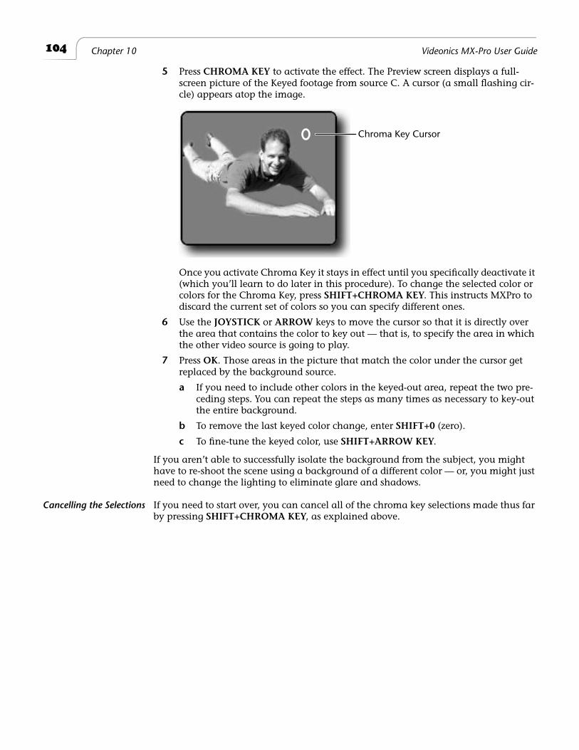
104
Chapter 10 Videonics MX-Pro User Guide
5
Press
CHROMA KEY
to activate the effect. The Preview screen displays a full-screen picture of the Keyed footage from source C. A cursor (a small flashing cir-cle) appears atop the image.
Once you activate Chroma Key it stays in effect until you specifically deactivate it (which you’ll learn to do later in this procedure). To change the selected color or colors for the Chroma Key, press
SHIFT+CHROMA KEY
. This instructs MXPro to discard the current set of colors so you can specify different ones.
6
Use the
JOYSTICK
or
ARROW
keys to move the cursor so that it is directly over the area that contains the color to key out — that is, to specify the area in which the other video source is going to play.
7
Press
OK
. Those areas in the picture that match the color under the cursor get replaced by the background source.
a
If you need to include other colors in the keyed-out area, repeat the two pre-ceding steps. You can repeat the steps as many times as necessary to key-out the entire background.
b
To remove the last keyed color change, enter
SHIFT+0
(zero).
c
To fine-tune the keyed color, use
SHIFT+ARROW KEY
.
If you aren’t able to successfully isolate the background from the subject, you might have to re-shoot the scene using a background of a different color — or, you might just need to change the lighting to eliminate glare and shadows.
Cancelling the Selections
If you need to start over, you can cancel all of the chroma key selections made thus far by pressing
SHIFT+CHROMA KEY
, as explained above.
Chroma Key Cursor
105
Chroma Key Performing the Chroma Key
P
ERFORMING
THE
C
HROMA
K
EY
When the Preview screen shows the desired chroma key results:
¨
Press
PLAY
. The Output monitor shows the Chroma Keyed image. Press
PLAY
again to cut back to the background source.
You can also dissolve between the Background footage and the Chroma Key foot-age using the
T-BAR
, rather than pressing
PLAY
.
Using Freeze and OtherInput Effects
You can apply Input Effects (including Freeze) to the Background footage, but
not
to the Keyed footage.
¨
To apply the freeze effect, press
FREEZE
either before or after pressing
CHROMA KEY
or
SHIFT+CHROMA KEY
.
¨
To apply any of the other Input Effects, apply them to the CURRENT source
before
pressing
CHROMA KEY
. MXPro ignores effects applied to the NEXT source during Chroma Key.
Fine-Tuning Key Colors
You can fine-tune the chroma key effect so that more or less of the keyed footage gets keyed. You can separately adjust the range of colors and video brightness that get keyed.
• To adjust the
brightness
range, enter
SHIFT+UP ARROW
to increase the range of brightness values that get keyed, replacing more of the keyed footage with the background footage. Use
SHIFT+DOWN ARROW
to decrease the brightness range, reducing the portion of the image that gets keyed.
• To adjust the
color range
, enter
SHIFT+RIGHT ARROW
to increase the range of colors that get keyed, replacing more of the keyed footage. Use
SHIFT+LEFT ARROW
to decrease the range of key-colors, reducing the portion of the image that gets keyed.
Ending Chroma Key
When you finish using chroma key, press
CHROMA KEY
.

®
Notes
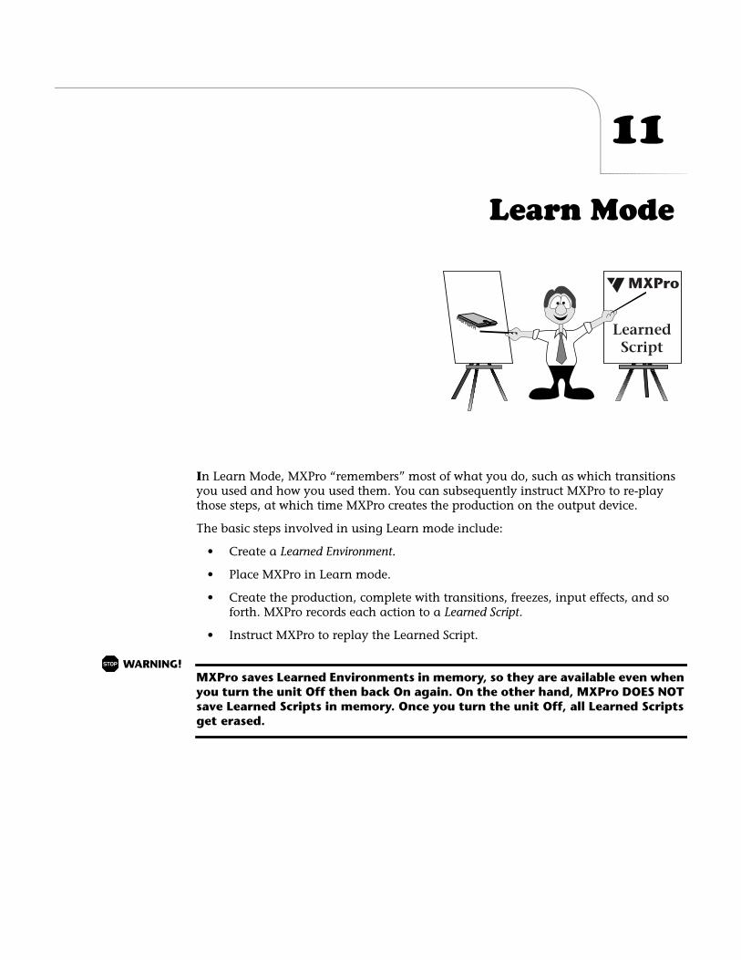
11
Learn Mode
I
n Learn Mode, MXPro “remembers” most of what you do, such as which transitions you used and how you used them. You can subsequently instruct MXPro to re-play those steps, at which time MXPro creates the production on the output device.
The basic steps involved in using Learn mode include:
• Create a
Learned Environment.
• Place MXPro in Learn mode.
• Create the production, complete with transitions, freezes, input effects, and so forth. MXPro records each action to a
Learned Script
.
• Instruct MXPro to replay the Learned Script.
WARNING!
MXPro saves Learned Environments in memory, so they are available even when you turn the unit Off then back On again. On the other hand, MXPro DOES NOT save Learned Scripts in memory. Once you turn the unit Off, all Learned Scripts
get erased.
MXPro
LearnedScript
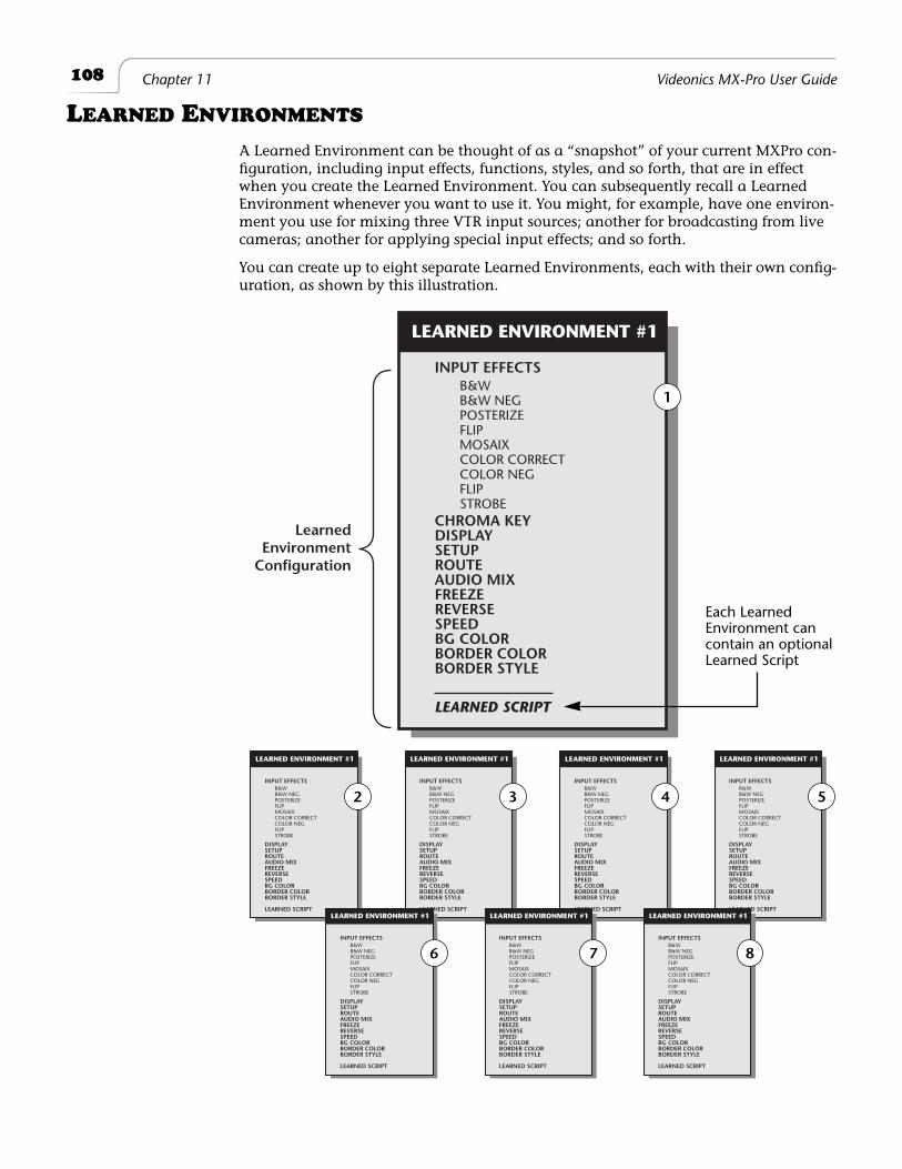
108
Chapter 11 Videonics MX-Pro User Guide
L
EARNED
E
NVIRONMENTS
A Learned Environment can be thought of as a “snapshot” of your current MXPro con-figuration, including input effects, functions, styles, and so forth, that are in effect when you create the Learned Environment. You can subsequently recall a Learned Environment whenever you want to use it. You might, for example, have one environ-ment you use for mixing three VTR input sources; another for broadcasting from live cameras; another for applying special input effects; and so forth.
You can create up to eight separate Learned Environments, each with their own config-uration, as shown by this illustration.
INPUT EFFECTS
CHROMA KEYDISPLAYSETUPROUTEAUDIO MIXFREEZEREVERSESPEEDBG COLORBORDER COLORBORDER STYLE
B&WB&W NEGPOSTERIZEFLIPMOSAIXCOLOR CORRECTCOLOR NEGFLIPSTROBE
LEARNED SCRIPT
LEARNED ENVIRONMENT #1
INPUT EFFECTS
DISPLAYSETUPROUTEAUDIO MIXFREEZEREVERSESPEEDBG COLORBORDER COLORBORDER STYLE
B&WB&W NEGPOSTERIZEFLIPMOSAIXCOLOR CORRECTCOLOR NEGFLIPSTROBE
LEARNED SCRIPT
LEARNED ENVIRONMENT #1
INPUT EFFECTS
DISPLAYSETUPROUTEAUDIO MIXFREEZEREVERSESPEEDBG COLORBORDER COLORBORDER STYLE
B&WB&W NEGPOSTERIZEFLIPMOSAIXCOLOR CORRECTCOLOR NEGFLIPSTROBE
LEARNED SCRIPT
LEARNED ENVIRONMENT #1
INPUT EFFECTS
DISPLAYSETUPROUTEAUDIO MIXFREEZEREVERSESPEEDBG COLORBORDER COLORBORDER STYLE
B&WB&W NEGPOSTERIZEFLIPMOSAIXCOLOR CORRECTCOLOR NEGFLIPSTROBE
LEARNED SCRIPT
LEARNED ENVIRONMENT #1
INPUT EFFECTS
DISPLAYSETUPROUTEAUDIO MIXFREEZEREVERSESPEEDBG COLORBORDER COLORBORDER STYLE
B&WB&W NEGPOSTERIZEFLIPMOSAIXCOLOR CORRECTCOLOR NEGFLIPSTROBE
LEARNED SCRIPT
LEARNED ENVIRONMENT #1
INPUT EFFECTS
DISPLAYSETUPROUTEAUDIO MIXFREEZEREVERSESPEEDBG COLORBORDER COLORBORDER STYLE
B&WB&W NEGPOSTERIZEFLIPMOSAIXCOLOR CORRECTCOLOR NEGFLIPSTROBE
LEARNED SCRIPT
LEARNED ENVIRONMENT #1
INPUT EFFECTS
DISPLAYSETUPROUTEAUDIO MIXFREEZEREVERSESPEEDBG COLORBORDER COLORBORDER STYLE
B&WB&W NEGPOSTERIZEFLIPMOSAIXCOLOR CORRECTCOLOR NEGFLIPSTROBE
LEARNED SCRIPT
LEARNED ENVIRONMENT #1
INPUT EFFECTS
DISPLAYSETUPROUTEAUDIO MIXFREEZEREVERSESPEEDBG COLORBORDER COLORBORDER STYLE
B&WB&W NEGPOSTERIZEFLIPMOSAIXCOLOR CORRECTCOLOR NEGFLIPSTROBE
LEARNED SCRIPT
LEARNED ENVIRONMENT #1
LearnedEnvironment
Configuration
2 3 4 5
6 7 8
1
Each LearnedEnvironment cancontain an optionalLearned Script
109
Learn Mode Learned Scripts
Procedure
To create a Learned Environment:
1
Set up MXPro the way you want for this particular environment. This includes setting any input effects you want, selecting the initial CURRENT and NEXT sources, defining color, defining borders, and so forth.
2
Enter
LEARN+
<number>
, where
<number>
can be any value from 1 to 8.
MXPro saves all current settings under the number you enter. Note that the
INPUT EFFECTS
LED (or, light) flashes to let you know MXPro is in Learn Mode.
At this point, you can create a Learned Script to save
with
the current Learned Environment. See the following section for further instructions.
You can also save the environment
without
a Learned Script. To do so, just press
LEARN
to disengage Learn Mode.
L
EARNED
S
CRIPTS
Learned Scripts exist only within Learned Environments. Although you can create a Learned Script without first specifically creating a Learned Environment, MXPro auto-matically creates a Learned Environment using the current settings.
You can record one Learned Script for each Learned Environment. So, because you can create 8 Learned Environments, you can also create 8 Learned Scripts.
The total number of actions (or,
steps
) in all of the combined Learned Scripts cannot exceed 250. If you attempt to exceed this number, MXPro simply stops recording steps when it reaches capacity. You can replay all steps learned up to that point.
MXPro does
not
retain Learned Scripts when you turn the unit off, but it does retain the Learned Environment. Therefore, if you create a Learned Script within a Learned Envi-ronment then turn off MXPro, the Learned Environment is retained, but the Learned Script is not.
MXPro does
not
record the following steps while in Learn mode:
• Create or transition to Compose screens
• Use Chroma Key
• Use PIPs
• Use the Demo
You cannot modify a Learned Script after creating it. If you need to modify a Learned Script, you must re-record it from the beginning.
If you’re familiar with the video-related term “Edit Decision List,” MXPro is
not
an EDL. MXPro simply records certain steps, then replays them at your direction.
About Steps
Most individual actions count as one step. For example, if you enter a two-digit transi-tion number on the keyboard, that counts as two steps: each time you press
PLAY
or use the
T-BAR
, that also counts as one step: and so forth.
110
Chapter 11 Videonics MX-Pro User Guide
Other buttons count as one step, including
SPEED
,
FREEZE
,
SETUP
,
INPUT EFFECTS
,
ARROW
keys,
CURRENT
and
NEXT
sources, and so forth.
Example…
The following Learned Script consists of 7 individual steps:
1
Press
NEXT/B
to select that device as the NEXT source (step one).
2
Press
SPEED
to increase the speed of the transition (step two).
3
Press
SPEED
again to increase the transition speed one more unit (step three).
4
Press
SPEED
once more to increase transition speed another unit (step four).
5
Enter
55
to designate that transition (steps five and six).
It requires two steps to enter the two digits.
6
Press
PLAY
(step seven).
Tip
Using
ARROW
keys to select a transition consumes one step for each key pressed. In most cases, to fit as many transitions as possible into a Learned Script, use the numeric keypad to
enter transition numbers rather than using the
ARROW
keys.
Tip
Select the CURRENT and NEXT sources before entering LEARN mode. LEARN mode interprets
pressing the CUT button as a transition.
111
Learn Mode Using Learn Mode
U
SING
L
EARN
M
ODE
Procedure
Learn mode involves the following steps:
1
Activate all devices.
Turn on MXPro and all devices you intend to use, if necessary.
2
Press
LEARN+
<number>
to engage Learn mode, where
<number>
can be any value from 1 to 8. The number designates the Learned Environment you want to use.
Note that the
INPUT EFFECTS
LED (or, light) flashes while MXPro is in Learn mode.
3
Enter production steps.
Create the production in the same way you would even if you weren’t using Learn mode.
4
Stop recording press
LEARN
again to disengage Learn Mode.
Learn mode disengages automatically if you exceed 250 total steps, the maxi-mum allowed in all combined Learned Scripts.
5
Play back the Learned Script.
a
Enter
SHIFT+LEARN+
<learned script #>
on the keyboard, where
<learned script #>
is the number of the Learned Environment and Learned Script you want to play back. Remember, the Learned Environment/Learned Script numbers can range from 1 through 8, inclusive.
b
Press
PLAY
or use the
T-BAR
to run each step in a Learned Script. When you use the
T-BAR
, you can manually control any transition in the Learned Script.
MXPro begins replaying the Learned Script and displays and/or records the results to the output device. (If the MXPro Preview screen is not currently visible on the Preview monitor, press
DISPLAY
until it appears.)
You can also use a GPI trigger device to play the steps in a Learned Script. A GPI trigger device works exactly the same as pressing
SHIFT+LEARN
. See “Using a GPI Device” beginning on page 126 for more information.
CAUTION
You cannot edit a Learned Script. The only way to change a Learned Script is to reen-ter it from the beginning. If you recall a Learned Script and begin entering commands,
MXPro OVERWRITES the previous script.
112
Chapter 11 Videonics MX-Pro User Guide
O
THER
USEFUL INFORMATION
When MXPro comes to the end of a Learned Script, it stops. You can re-initiate the same or any other Learned Script by entering the SHIFT+LEARN+<learned script #> for the script you want to run.
You can do the following in a Learned Script:
¨ Perform transitions, including use of Reverse and Speed settings.
¨ Choose CURRENT and NEXT sources.
¨ Use the Freeze function.
¨ Transition audio, video, or both.
You cannot do the following in a Learned Script:
¨ Create or transition to Compose screens.
¨ Use Chroma Key.
¨ Use the Demo.
¨ Use PIPs.
MXPro memorizes a manual transition (such as when using the T-BAR) as an auto-matic transition at the currently set speed — that is, it is remembered as if you had used the PLAY button rather than the T-BAR.
MXPro erases a Learned Script when:
¨ You turn off MXPro.
¨ MXPro loses power (such as a power failure).
¨ You overwrite an existing Learned Script.
ABORTING A PLAYBACK SESSION
Once MXPro begins playing back a Learned Script, you can abort the playback session, by pressing LEARN.
Once you end playback of a Learned Script, the PLAY button and the T-BAR act nor-mally, playing the effect indicated on the screen rather than the Learned Script.
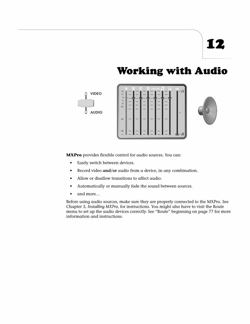
12
Working with Audio
MXPro
provides flexible control for audio sources. You can:
• Easily switch between devices.
• Record video
and/or
audio from a device, in any combination.
• Allow or disallow transitions to affect audio.
• Automatically or manually fade the sound between sources.
• and more…
Before using audio sources, make sure they are properly connected to the MXPro. See Chapter 3,
Installing MXPro
, for instructions. You might also have to visit the Route menu to set up the audio devices correctly. See “Route” beginning on page 77 for more information and instructions.
MIXCOLOR+6
+3
0
-3
-6
-10
-20
-30
-°
VIDEO
AUDIO
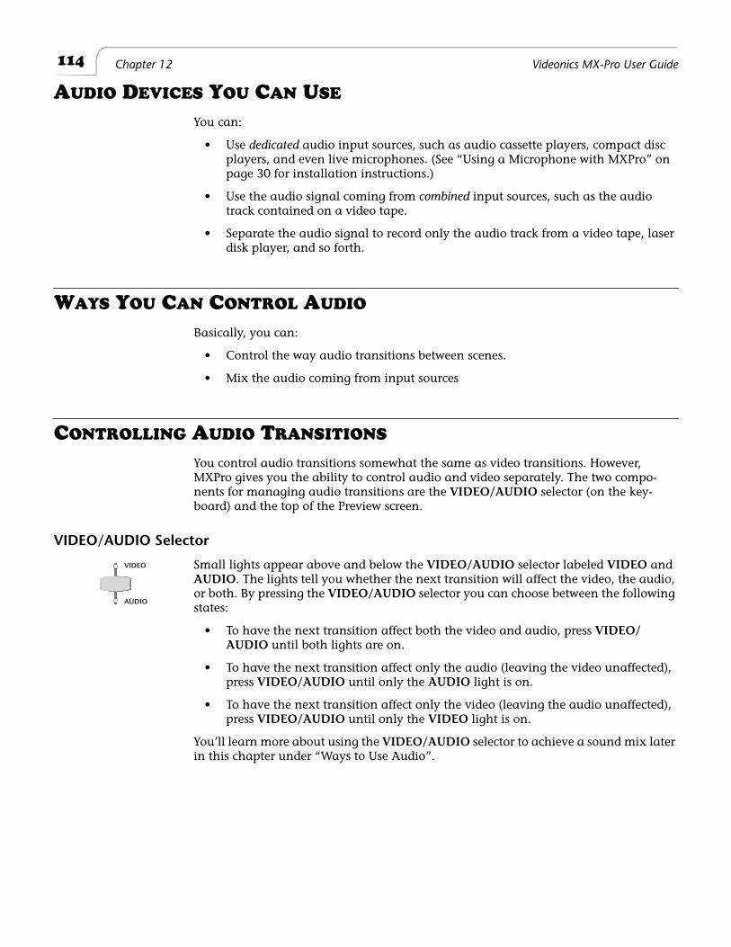
114
Chapter 12 Videonics MX-Pro User Guide
A
UDIO
D
EVICES
Y
OU
C
AN
U
SE
You can:
• Use
dedicated
audio input sources, such as audio cassette players, compact disc players, and even live microphones. (See “Using a Microphone with MXPro” on page 30 for installation instructions.)
• Use the audio signal coming from
combined
input sources, such as the audio track contained on a video tape.
• Separate the audio signal to record only the audio track from a video tape, laser disk player, and so forth.
W
AYS
Y
OU
C
AN
C
ONTROL
A
UDIO
Basically, you can:
• Control the way audio transitions between scenes.
• Mix the audio coming from input sources
C
ONTROLLING
A
UDIO
T
RANSITIONS
You control audio transitions somewhat the same as video transitions. However, MXPro gives you the ability to control audio and video separately. The two compo-nents for managing audio transitions are the
VIDEO/AUDIO
selector (on the key-board) and the top of the Preview screen.
VIDEO/AUDIO Selector
Small lights appear above and below the
VIDEO/AUDIO
selector labeled
VIDEO
and
AUDIO
. The lights tell you whether the next transition will affect the video, the audio, or both. By pressing the
VIDEO/AUDIO
selector you can choose between the following states:
• To have the next transition affect both the video and audio, press
VIDEO/AUDIO
until both lights are on.
• To have the next transition affect only the audio (leaving the video unaffected), press
VIDEO/AUDIO
until only the
AUDIO
light is on.
• To have the next transition affect only the video (leaving the audio unaffected), press
VIDEO/AUDIO
until only the
VIDEO
light is on.
You’ll learn more about using the
VIDEO/AUDIO
selector to achieve a sound mix later in this chapter under “Ways to Use Audio”.
VIDEO
AUDIO
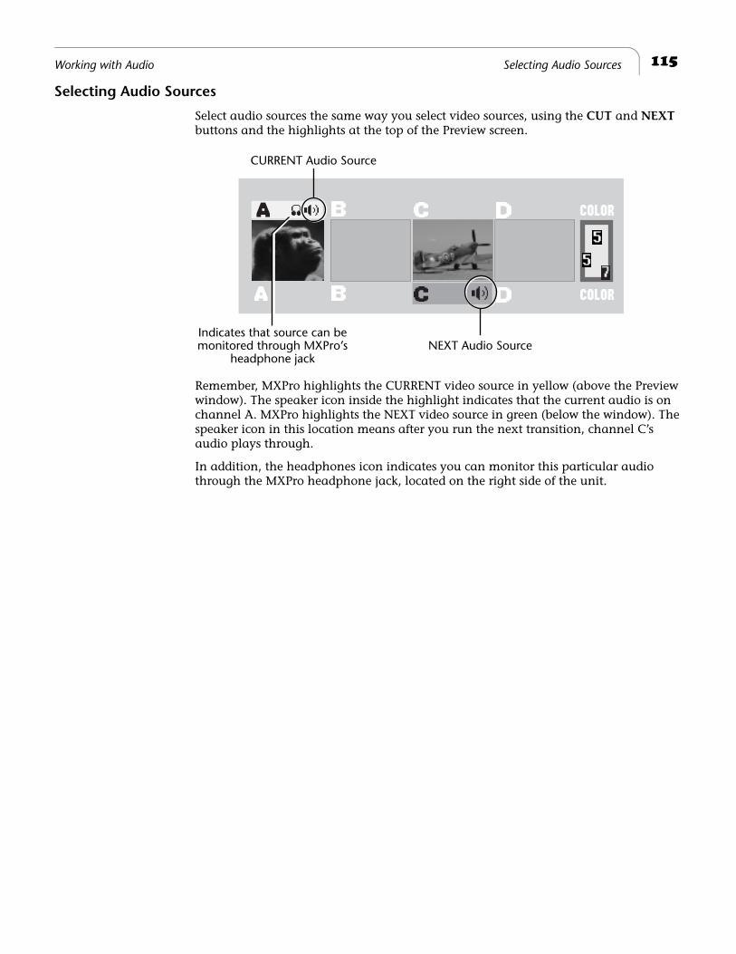
115
Working with Audio Selecting Audio Sources
Selecting Audio Sources
Select audio sources the same way you select video sources, using the
CUT
and
NEXT
buttons and the highlights at the top of the Preview screen.
Remember, MXPro highlights the CURRENT video source in yellow (above the Preview window). The speaker icon inside the highlight indicates that the current audio is on channel A. MXPro highlights the NEXT video source in green (below the window). The speaker icon in this location means after you run the next transition, channel C’s audio plays through.
In addition, the headphones icon indicates you can monitor this particular audio through the MXPro headphone jack, located on the right side of the unit.
CURRENT Audio Source
NEXT Audio SourceIndicates that source can bemonitored through MXPro’s
headphone jack
116
Chapter 12 Videonics MX-Pro User Guide
W
AYS
TO
U
SE
A
UDIO
You can manage audio in several different ways during video transitions. This section explains some of the more useful methods.
Audio Accompanies Video
When you transition from one source to another, you might want the
native
audio (that is, the sound recorded on the original media) to transition right along with the video.
Example…
Suppose you want to dissolve from a shot of a car arriving in front of a house, to a shot of the person entering the house through the front door. In this case, you might want to hear the car
drive up, then hear the door to the house open.
Procedure
To have audio accompany video and follow the same transition:
1
Set up the CURRENT and NEXT sources, and choose a transition.
2
Press
VIDEO/AUDIO
until both the
VIDEO
and
AUDIO
lights are on.
3
Press
PLAY
or use the
T-BAR
to run the transition.
Both the video and audio transition, together. The audio mixes together — that is, audio from the first video scene fades away gradually as the audio from the next scene fades in and mixes with the original audio.
You can control the duration of the fade by adjusting the speed of the transition. A slow transition fades the sound slowly, whereas a fast transition fades the sound quickly. (See “Changing Transition Speed” on page 58.) If you use a Cut transition, the sound switches abruptly.
VIDEO
AUDIO
117
Working with Audio Continuous Audio
Continuous Audio
Example…
Suppose you taped a musical concert using two cameras. The first camera focuses on the musicians and picks up the audio. The second camera focuses around the audience to get the reactions of different listeners. You want to mix together the footage from both cameras, but
have only the audio from the first camera play through all transitions.
Procedure
To use continuous audio:
1
Set up the CURRENT and NEXT sources, and choose a transition.
Assume the tape from the first camera is on channel A, and the tape from the second on channel B. Press
CUT/A
to make it the CURRENT source, press
NEXT/B
to make it the NEXT source.
2
Press
VIDEO/AUDIO
until only the
VIDEO
light is on.
This tells MXPro that when the transition runs, only the video changes. For example, press
CUT
to jump from the stage to the audience and the video on channel A continues to play during the transition and into the next scene.
3
Continue pressing
CUT
(or using other transitions) to switch back and forth between the stage and the audience.
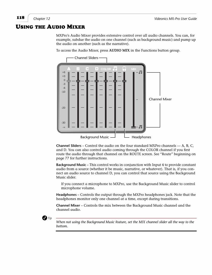
118
Chapter 12 Videonics MX-Pro User Guide
U
SING
THE
A
UDIO
M
IXER
MXPro’s Audio Mixer provides extensive control over all audio channels. You can, for example, subdue the audio on one channel (such as background music) and pump up the audio on another (such as the narrative).
To access the Audio Mixer, press
AUDIO MIX
in the Functions button group.
Channel Sliders
– Control the audio on the four standard MXPro channels — A, B, C, and D. You can also control audio coming through the COLOR channel if you first route the audio through that channel on the ROUTE screen. See “Route” beginning on page 77 for further instructions.
Background Music
– This control works in conjunction with Input 4 to provide constant audio from a source (whether it be music, narrative, or whatever). That is, if you con-nect an audio source to channel D, you can control that source using the Background Music slider.
If you connect a microphone to MXPro, use the Background Music slider to control microphone volume.
Headphones – Controls the output through the MXPro headphones jack. Note that the headphones monitor only one channel at a time, except during transitions.
Channel Mixer – Controls the mix between the Background Music channel and the channel audio.
TipWhen not using the Background Music feature, set the MIX channel slider all the way to the bottom.
MIXCOLOR+6
+3
0
-3
-6
-10
-20
-30
-°
HeadphonesBackground Music
Channel Sliders
Channel Mixer
119Working with Audio Audio Mixer Controls
Audio Mixer Controls
The default settings in the Audio Mixer have all channels at 0 (zero) db. The MIX channel, however, is set at its mid-way point. Channel A is selected, as indicated by its highlighting.
The following tables explain how to operate the Audio Mixer controls from the MXPro keyboard.
Using Background Audio
MXPro’s Input 4 has a special feature — you can use it for background music. To con-trol the level of the music, use the Background Music slider in the Audio Mixer. Use the keyboard controls shown in the preceding table to adjust the audio level.
Depending on how you set things up, the CURRENT source transitions to the NEXT source and the background music plays uninterrupted between them. The audio from the CURRENT and NEXT sources normally follows the video transitions — for example, if you set up a dissolve transition, audio from the CURRENT source fades away, then the audio from the NEXT source fades in.
Table 13: Selecting Mixer Channels
To… Use these keys…
Select consecutive channels LEFT ARROW and RIGHT ARROW
Select a specific channel NEXT/ANEXT/BNEXT/C NEXT/DNEXT/COLOR
Select left-most channel SHIFT+LEFT ARROW
Select right-most channel SHIFT+RIGHT ARROW
Table 14: Adjusting Audio Levels
To… Use these keys…
Raise level one tick UP ARROW
Lower level one tick DOWN ARROW
Raise level ten ticks SHIFT+UP ARROW
Lower level ten ticks SHIFT+DOWN ARROW
Raise/Lower level arbitrarily T-BAR
Control mix between Background Music and channel audio
SHIFT+T-BAR
Restore previous slider positions SHIFT+0 (zero)
120 Chapter 12 Videonics MX-Pro User Guide
USING HEADPHONES
You might find headphones helpful for monitoring audio input signals. You can plug a set of headphones directly into the MXPro by connecting them to the Headphone jack located on the right side of the unit, next to the Power switch.
NoteYou can use stereophonic headphones, but the audio is always monaural — that is, MXPro mixes the left and right channels together. However, stereo quality is retained when sending the audio to the output device.
Normally, headphones carry only the main sound — that is, the sound coming from the CURRENT input source. You can, however, monitor the sound from the NEXT source without disturbing the audio going to the output device.
Procedure
To monitor the audio on the NEXT source:
¨ Press SHIFT+AUDIO MIX.
Each time you press SHIFT+AUDIO MIX you toggle between the audio on the CURRENT source and that on the NEXT source.
ADVANCED AUDIO SETUPS
If you have an external audio mixer device available, we recommend you use that device to manually control all sound. You can:
• Bypass the MXPro completely and connect the external mixer’s output directly to the output’s audio input; or,
• Connect the external mixer’s output to any MXPro audio input, and perma-nently set that source as your sound input source. This lets you to use the exter-nal mixer when you need flexibility, or use MXPro when you want control of the audio. The latter gives you the ability to do more things, like fading audio auto-matically while video transitions run.
13
Advanced Operations
T
his chapter discusses operations you might not use very often, but are quite helpful when you need them. They include:
• Using Titles with MXPro
• Using Color Bars
• Performing Roll Edits
• Operating in Live Environments
• Security Monitoring
• Using a GPI Device
• Calibrating the
T-BAR
• Resetting MXPro to Factory Defaults
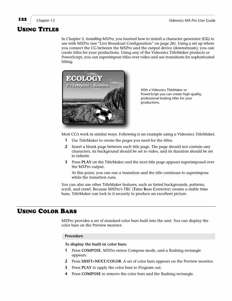
122
Chapter 13 Videonics MX-Pro User Guide
U
SING
T
ITLES
In Chapter 3,
Installing MXPro
, you learned how to install a character generator (
CG
) to use with MXPro (see “Live Broadcast Configuration” on page 26). Using a set up where you connect the CG between the MXPro and the output device (downstream), you can create titles for your productions. Using any of the Videonics TitleMaker products or PowerScript, you can superimpose titles over video and use transitions for sophisticated titling.
Most CG’s work in similar ways. Following is an example using a Videonics TitleMaker.
1
Use TitleMaker to create the pages you need for the titles.
2
Insert a blank page between each title page. The page should not contain any characters, its background should be set to video, and its duration should be set to infinite.
3
Press
PLAY
on the TitleMaker and the next title page appears superimposed over the MXPro output.
At this point, you can run a transition and the title continues to superimpose while the transition runs.
You can also use other TitleMaker features, such as tinted backgrounds, patterns, scroll, and crawl. Because MXPro’s TBC (
T
ime
B
ase
C
orrector) creates a stable time base, TitleMaker can lock to it securely to produce an excellent picture.
U
SING
C
OLOR
B
ARS
MXPro provides a set of standard color bars built into the unit. You can display the color bars on the Preview monitor.
Procedure
To display the built-in color bars:
1
Press
COMPOSE
. MXPro enters Compose mode, and a flashing rectangle appears.
2
Press
SHIFT+NEXT/COLOR
. A set of color bars appears on the Preview monitor.
3
Press
PLAY
to apply the color bars to Program out.
4
Press
COMPOSE
to remove the color bars and the flashing rectangle.
With a Videonics TitleMaker or PowerScript you can create high-quality, professional-looking titles for your productions.
123
Advanced Operations Performing Roll Edits
P
ERFORMING
R
OLL
E
DITS
Two types of roll edits are commonly used in video editing —
A/A
rolls, and
A/B
rolls. You can do both types of rolls with MXPro. A/A rolls can be accomplished with relative ease. As you’ll learn later in this section, you can also do A/B roll editing with MXPro, although it does require good preparation and manual control of the devices. If you intend to do a lot of A/B roll editing, we recommend you consider a dedicated device, such as a Videonics A/B Roll Editor.
Cutting Between Scenes
Simple cuts between scenes do not require special features. All you have to do is pause the recording VCR at the end of one scene, then release pause when the next scene begins.
A/A Roll Edits
A/A roll edits can be defined as Single-Source editing because all of the original materi-als come from a single videotape. MXPro offers special features designed specifically for these types of situations.
An easy way to add interest to a single-source transition is to use the A/A roll edit (sometimes called an A/X/A edit). In this situation, the video freezes at the end of one scene, then a dissolve or other effect transitions to the next scene.
Example…
You are producing a murder mystery. The door opens and the villain sneaks into the room. Slowly he moves toward the camera, then you press
FREEZE
to freeze the killer’s menacing glare!
Next, you pause the recorder and set up MXPro to perform a dissolve. Then you find the next scene and start it playing a bit before the scene starts. There’s the victim — it’s granny, sitting in a rocking chair with her back to the camera. You start the recorder. It’s still recording the frozen picture. At the correct moment you transition from the frozen closeup of the murderer to granny in her chair. As the killer’s face dissolves away, granny turns and we discover it’s the
constable, ready to arrest the scoundrel!
Procedure
To perform a roll edit such as this:
1
Roll the tape and press
FREEZE
at the appropriate moment to freeze the end of the scene.
2
Pause the recording device.
3
Set up the transition you want.
4
Position the source tape just before the next scene and let the scene play.
5
Release pause on the recording device to record more of the frozen picture.
6
At the appropriate moment, run the transition between the frozen picture and the rolling video from the next scene.
This type of A/A roll works best when the recording device has flying-erase heads — a feature that lets the VCR make a clean break when you pause the recording.
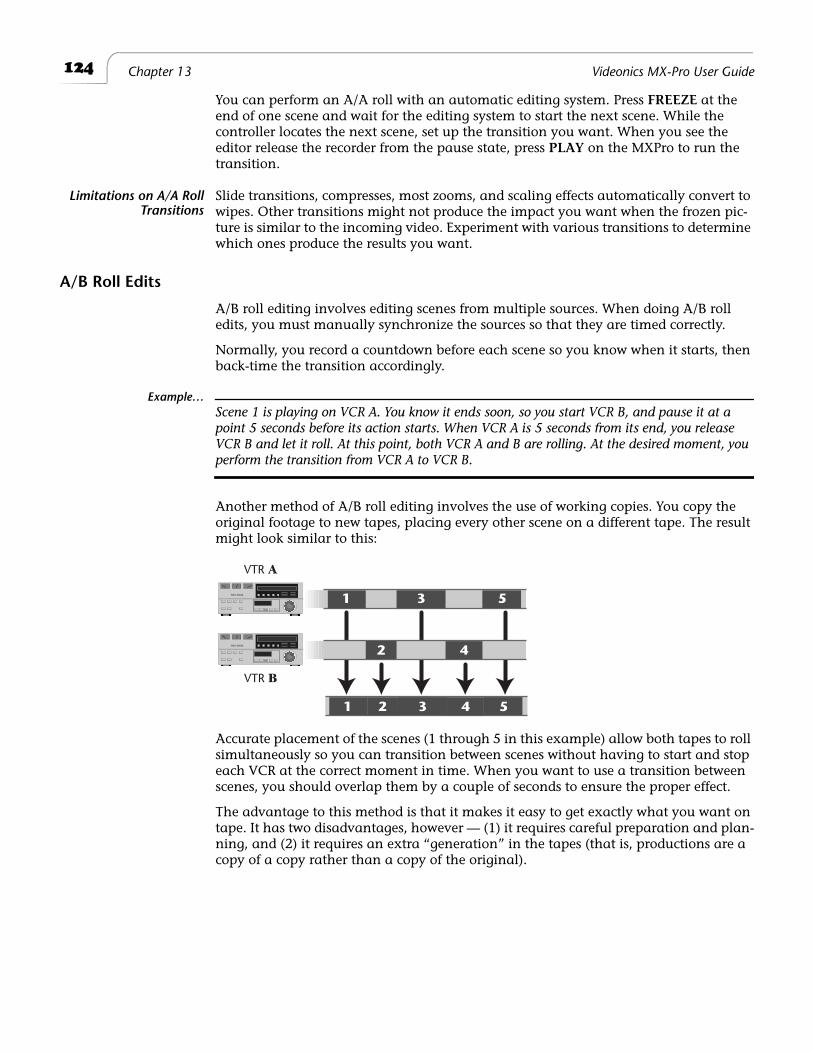
124
Chapter 13 Videonics MX-Pro User Guide
You can perform an A/A roll with an automatic editing system. Press
FREEZE
at the end of one scene and wait for the editing system to start the next scene. While the controller locates the next scene, set up the transition you want. When you see the editor release the recorder from the pause state, press
PLAY
on the MXPro to run the transition.
Limitations on A/A RollTransitions
Slide transitions, compresses, most zooms, and scaling effects automatically convert to wipes. Other transitions might not produce the impact you want when the frozen pic-ture is similar to the incoming video. Experiment with various transitions to determine which ones produce the results you want.
A/B Roll Edits
A/B roll editing involves editing scenes from multiple sources. When doing A/B roll edits, you must manually synchronize the sources so that they are timed correctly.
Normally, you record a countdown before each scene so you know when it starts, then back-time the transition accordingly.
Example…
Scene 1 is playing on VCR A. You know it ends soon, so you start VCR B, and pause it at a point 5 seconds before its action starts. When VCR A is 5 seconds from its end, you release VCR B and let it roll. At this point, both VCR A and B are rolling. At the desired moment, you
perform the transition from VCR A to VCR B.
Another method of A/B roll editing involves the use of working copies. You copy the original footage to new tapes, placing every other scene on a different tape. The result might look similar to this:
Accurate placement of the scenes (1 through 5 in this example) allow both tapes to roll simultaneously so you can transition between scenes without having to start and stop each VCR at the correct moment in time. When you want to use a transition between scenes, you should overlap them by a couple of seconds to ensure the proper effect.
The advantage to this method is that it makes it easy to get exactly what you want on tape. It has two disadvantages, however — (1) it requires careful preparation and plan-ning, and (2) it requires an extra “generation” in the tapes (that is, productions are a copy of a copy rather than a copy of the original).
1 3 5
1 2 43 5
2 4
VTR A
VTR B
125
Advanced Operations Transitions TO and FROM Solid Colors
Transitions TO and FROM Solid Colors
You can insert a solid color background between two scenes for impact. For example, scene one dissolves to solid black, holds briefly, then dissolves from black to the next scene.
Procedure
To run this type of transition:
1
Assume your CURRENT source is on Channel A — press
CUT/A
to ensure it is the current one.
2
Select the transition you want to use from the Transitions Menu — in this exam-ple, select a slow dissolve.
3
Press
NEXT/COLOR
to activate the Color Selector on the Preview screen.
4
Press
BG COLOR
as many times as necessary to make the background black.
5
Press
PLAY
to run the transition and fade to black.
6
Assume your NEXT source (the one you are transitioning into) is on Channel C — press
NEXT/C
to make that the next source.
7
Select the transition you want to use from the Transitions Menu — again, for this example select a slow dissolve.
8
Press
PLAY
to transition from solid black to Channel C.
Tip
Use a wipe or dissolve to and from a solid colored background to indicate passage in time, a change in mood, or a change in scenery. For example, a red background might indicate anger or frustration; light green might indicate an open forest (tranquility) and dark green a rain for-
est (somber and cool).
Transitions to Modified Sources
Use MXPro’s Input Effects to create a modified version of a source. This lets you transi-tion between the modified and unmodified versions. For the following procedure, assume you want to flip a source image to create a
mirror image
.
Procedure
To run this type of transition:
1
Use MXPro’s Route function to make the same source appear on two different channels. For example, route channels A and B to IN 1 on the ROUTE screen. (See “Route” on page 77.)
2
Enter
SHIFT+FLIP
(horizontal) to apply the effect.
3
Select a transition (such as number 6) to run between channels A and B.
4
Press
PLAY
or move the
T-BAR
to run the transition.
Prior to running the transition, the source appears normal. After running the transi-tion, the source appears as a mirror-image of itself.
126
Chapter 13 Videonics MX-Pro User Guide
O
PERATING
IN
L
IVE
E
NVIRONMENTS
In most live environments you need the ability to quickly and easily switch between the various live feeds. MXPro serves this need well because you can view the four input sources on the Preview screen and easily run transitions from the CURRENT to the NEXT feed simply by pressing
PLAY or moving the T-BAR.
SECURITY MONITORING
MXPro also serves well for monitoring security cameras. For example, you might set up four different cameras and train them on areas that require security coverage. The Pre-view screen shows small images from each camera. Switch to FULL Preview (SHIFT+3) to see larger previews from all cameras. When you want to see a full screen image of a specific area, simply press the CUT button for that camera.
USING A GPI DEVICE
You can connect a GPI (General Purpose Interface) device to MXPro. The GPI device can trigger an event from an external source, such as a push-button switch or an edit controller with GPI output. A GPI device is especially useful when you are positioned some distance away from MXPro but still want to be able to control its operation.
A GPI pulse causes MXPro to behave exactly as if the play button were pressed. Nor-mally, it starts a transition you previously set up. If you have created a Learned sequence (see Chapter 11, Learn Mode), it triggers the next event in the sequence.
An edit controller or computer that provides a contact closure can also serve as a GPI triggering device.
WARNING!Do not connect a power source of any kind to the Control GPI input connector on the MXPro. Doing so can damage the equipment and void your warranty.
You can use a remote push-button device to trigger events on MXPro. If you already have a GPI device you want to use, refer to “Live Broadcast Configuration” on page 26 to learn how to connect the device. If you do not have a GPI device but would like to build one, refer to the instructions in the next section.
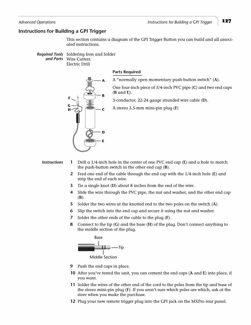
127Advanced Operations Instructions for Building a GPI Trigger
Instructions for Building a GPI Trigger
This section contains a diagram of the GPI Trigger Button you can build and all associ-ated instructions.
Required Toolsand Parts
Soldering Iron and SolderWire CuttersElectric Drill
Parts Required
A “normally open momentary push-button switch” (A).
One four-inch piece of 3/4-inch PVC pipe (C) and two end caps (B and E).
3-conductor, 22-24 gauge stranded wire cable (D).
A stereo 3.5-mm mini-pin plug (F)
Instructions 1 Drill a 1/4-inch hole in the center of one PVC end cap (E) and a hole to match the push-button switch in the other end cap (B).
2 Feed one end of the cable through the end cap with the 1/4-inch hole (E) and strip the end of each wire.
3 Tie a single knot (D) about 8 inches from the end of the wire.
4 Slide the wire through the PVC pipe, the nut and washer, and the other end cap (B).
5 Solder the two wires at the knotted end to the two poles on the switch (A).
6 Slip the switch into the end cap and secure it using the nut and washer.
7 Solder the other ends of the cable to the plug (F).
8 Connect to the tip (G) and the base (H) of the plug. Don’t connect anything to the middle section of the plug.
9 Push the end caps in place.
10 After you’ve tested the unit, you can cement the end caps (A and E) into place, if you want.
11 Solder the wires of the other end of the cord to the poles from the tip and base of the stereo mini-pin plug (F). If you aren’t sure which poles are which, ask at the store when you make the purchase.
12 Plug your new remote trigger plug into the GPI jack on the MXPro rear panel.
F
A
C
D
GH
B
E
Tip
Base
Middle Section
128 Chapter 13 Videonics MX-Pro User Guide
Using a GPI Trigger Device
If your edit controller is automatic and has GPI trigger, you can trigger each page in a project with the controller. You might need a special cable to connect the GPI jacks from the GPI device to MXPro.
WARNING!Always turn off power before plugging into any GPI jack.
The following instructions explain how to automatically trigger events using the device described above. Instructions for other devices should be similar, but you should check the device instructions beforehand.
Procedure
To use a GPI device as a trigger:
1 Connect the GPI device to MXPro using an appropriate cable.
2 Press the GPI trigger button when you want to trigger an event. You can trigger events between scenes or anywhere in the middle of a scene. You can also trigger each event in a Learned Script (see “Learned Scripts” beginning on page 109).
CALIBRATING THE T-BAR
If you suspect that the T-BAR is not functioning properly, it might need re-calibration. A symptom of an incorrectly calibrated T-BAR might be that transitions do not run correctly from start-to-finish in each direction.
Procedure
To re-calibrate the T-BAR:
1 Turn MXPro off.
2 Press and hold SHIFT+INPUT EFFECTS while turning the unit back on.
3 When the LED light above INPUT EFFECTS comes on, release SHIFT and INPUT EFFECTS.
4 Move the T-BAR near the top of its slot, then press the UP ARROW key. The Video LED (above the VIDEO/AUDIO selector) lights up.
5 Move the T-BAR near the bottom of its slot, then press the DOWN ARROW key. The Audio LED (below the VIDEO/AUDIO selector) lights up.
6 Press OK.
All LED’s on the unit go out and MXPro automatically re-initializes itself. The T-BAR is now properly calibrated.
VIDEO
AUDIO
Video/Audio Selector
LED’s
Do not push the T-BAR hard against the top or bottom of its slot during calibration. This over-calibrates the T-BAR and might prevent transitions from executing properly.
129Advanced Operations Resetting MXPro Factory Defaults
RESETTING MXPRO FACTORY DEFAULTS
When you first power up MXPro, it operates using settings defined by Videonics. As you go about using MXPro and changing its various settings, the unit stores your settings in its memory (called NVRAM). You can reset all settings to their factory defaults.
Procedure
To reset MXPro to its factory defaults:
1 Power down the unit (using the Power switch).
2 Press down and hold the SHIFT and SETUP buttons.
3 Turn on MXPro’s Power switch.
4 After the unit powers up and you see the Preview screen, release all buttons.

®
Notes
A
Transitions List
This appendix shows the icons assigned to each MXPro transition, and identifies them by number.
Some transition descriptions use special terms and abbreviations to describe how the transitions work.
(A)
— The CURRENT source: the one on the screen before the transition begins.
(B)
— The NEXT source: the one on the screen after the transition finishes.
Dissolve
— One image fades away as another fades in.
Wipe
— A simple window or boundary that reveals the underlying video. The video image neither moves nor changes size.
Slide
— Leaves the video full size but the picture moves with the transition.
Comp, Exp
— (Compress, Expand) The video resizes to fit the window. Normally, the entire picture scales to fill the window.
H, V
— (Horizontal, Vertical) These refer to the direction in which the transition moves. For example, a V wipe is a horizontal line that moves vertically up or down the screen. When the effect runs in the forward (non-reversed) direction, vertical transitions move down the screen and horizontal transitions move from left to right, unless otherwise indicated.
CW, CCW
— ClockWise and CounterClockWise movement.
L, R, Ctr, T, B
— Left, Right, Center, Top, and Bottom, respectively.
TLC, TRC
— Top Left Corner and Top Right Corner, respectively.
BLC, BRC
— Bottom Left Corner and Bottom Right Corner, respectively.
“
;
” — Divides multi-step transitions. “
/
” indicates two actions that occur simulta-neously.
*
— The transition always uses a fixed direction when performed from frozen picture. They are not affected by the
REVERSE
button.
#
— The transition operates differently when performed from a frozen picture. Simpler effects are substituted automatically.
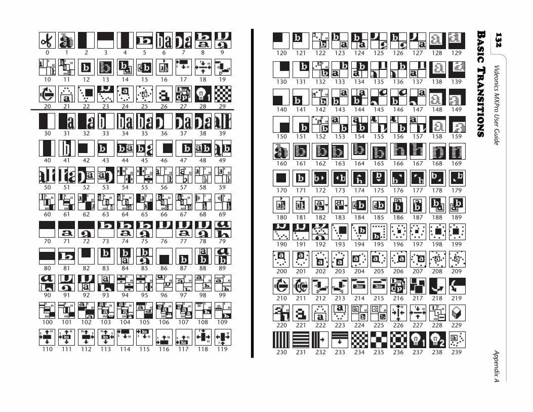
13
2
Videonics MX
Pro User G
uideAppendix A
B
AS
IC
T
RA
NS
ITIO
NS
30 31 32 33 34 35 36 37 38 39
40 41 42 43 44 45 46 47 48 49
50 51 52 53 54 55 56 57 58 59
0 1 2 3 4 5 6 7 8 9
10 11 12 13 14 15 16 17 18 19
20 21 22 23 24 25 26 27 28 29
60 61 62 63 64 65 66 67 68 69
70 71 72 73 74 75 76 77 78 79
80 81 82 83 84 85 86 87 88 89
90 91 92 93 94 95 96 97 98 99
100 101 102 103 104 105 106 107 108 109
110 111 112 113 114 115 116 117 118 119
130 131 132 133 134 135 136 137 138 139
120 121 122 123 124 125 126 127 128 129
140 141 142 143 144 145 146 147 148 149
150 151 152 153 154 155 156 157 158 159
160 161 162 163 164 165 166 167 168 169
170 171 172 173 174 175 176 177 178 179
180 181 182 183 184 185 186 187 188 189
190 191 192 193 194 195 196 197 198 199
200 201 202 203 204 205 206 207 208 209
210 211 212 213 214 215 216 217 218 219
220 221 222 223 224 225 226 227 228 229
230 231 232 233 234 235 236 237 238 239
133
Transitions List Basic Transitions
The Basic Transitions category contains transitions numbered from 0 through 239. The category contains a wide assortment of effects.
Transitions 0 through 29 serve as the default assortment in the Transitions Menu. When you turn the unit on for the first time, these transitions appear in the menu. They provide a unique assortment of transitions suitable for many purposes.
In the following table, transitions marked with * (asterisk) always use fixed direction when performed from a frozen picture. They are not affected by the
REVERSE
button.Transitions marked with # (pound sign) operate differently when performed from a fro-zen picture. Simpler effects are automatically substituted.
Table 15: Descriptions of Basic Transitions
# Description # Description
Default Transition Assortment
0 Cut 15# H Comp. (A) alongside (B) in motion; Exp. (B)
1 Dissolve 16 Comp. (A) to 1/2; roll R to (B); Exp2 H Wipe 17 Slide in slice (B) from L at T; Wipe slice to
full3 V Wipe 18 V Comp. (A) to Ctr slice; H collapse slice
to Ctr point4 H Curtain Wipe (B) from Ctr to full 19 Butterfly from T L/random proportion5 V Curtain Exp. (B) from Ctr to full 20 Ctr Exp. (B) with 2 flips6 H Slide (A)/Exp. (B) 21 Ctr Comp. (A); swing back; out B7 H Slide (A)/Slide (B) 22 Bounce off edges/Wipe8 V Comp. (A)/Exp. (B) 23 Bounce in from T9 V Slide (A)/Slide (B) 24* Comp. (A) to T; CW spiral out to T10# H Slide (A) out L; Slide (B) in from L 25* Comp. (A); CW spiral to Ctr11* H Comp. (A) R to 1/2 screen slice; Slide
to L; slide under Ctr line26# Mosaic Zoom
12 Ctr Exp. (B) 27 Random Sizes & Flips (B)13 Ctr Exp. & Dissolve (B) 28 Luminance Key 114# Comp. (A) to lower R of (B); Exp. (B) 29 Checkerboard w/middle dissolve
Other Basic Transitions
30 H Wipe 136 Diagonal Exp. (B) from TRC/Slide (A) to BLC
31* H Comp. (A)/Wipe (B) 137 Diag. Slide (B) from TRC/Comp. (A) to BLC
32* H Slide (A)/Wipe (B) 138* Diagonal Comp. & Dissolve (A) to TRC33 H Wipe (A)/Exp. (B) 139* Diagonal Slide & Dissolve (A) to TRC34 H Comp. (A)/Exp. (B) 140 Diagonal Wipe (B) from BLC35 H Slide (A)/Exp. (B) 141 Diagonal Exp. (B) from BLC36 H Wipe (A)/Slide (B) 142 Diagonal Comp. (B) to BLC; Exp.37 H Comp. (A)/Slide (B) 143 Diag. Exp. (B) from BLC/Comp. (A) to TRC38 H Slide (A)/Slide (B) 144 143, with overlap39 H Picture Roll 145 Diagonal Slide (B) from BLC/Slide (A) to
TRC40 H Curtain Wipe (B) from Ctr to full 146 Diagonal Exp. (B) from BLC/Slide (A) to
TRC41 H Curtain Exp. (B) from Ctr to full 147 Diag. Slide (B) from BLC/Comp. (A) to
TRC42 H Wipe (B) from L Ctr 148* Diagonal Comp. & Dissolve (A) to BLC43 H Exp. (B) from L Ctr 149* Diagonal Slide & Dissolve (A) to BLC
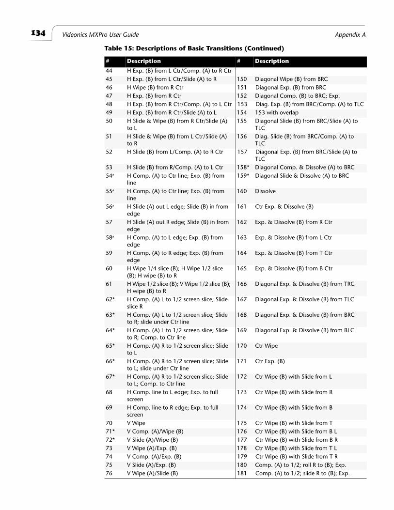
134
Videonics MXPro User Guide Appendix A
44 H Exp. (B) from L Ctr/Comp. (A) to R Ctr45 H Exp. (B) from L Ctr/Slide (A) to R 150 Diagonal Wipe (B) from BRC46 H Wipe (B) from R Ctr 151 Diagonal Exp. (B) from BRC47 H Exp. (B) from R Ctr 152 Diagonal Comp. (B) to BRC; Exp.48 H Exp. (B) from R Ctr/Comp. (A) to L Ctr 153 Diag. Exp. (B) from BRC/Comp. (A) to TLC49 H Exp. (B) from R Ctr/Slide (A) to L 154 153 with overlap50 H Slide & Wipe (B) from R Ctr/Slide (A)
to L155 Diagonal Slide (B) from BRC/Slide (A) to
TLC51 H Slide & Wipe (B) from L Ctr/Slide (A)
to R156 Diag. Slide (B) from BRC/Comp. (A) to
TLC52 H Slide (B) from L/Comp. (A) to R Ctr 157 Diagonal Exp. (B) from BRC/Slide (A) to
TLC53 H Slide (B) from R/Comp. (A) to L Ctr 158* Diagonal Comp. & Dissolve (A) to BRC54
#
H Comp. (A) to Ctr line; Exp. (B) from line
159* Diagonal Slide & Dissolve (A) to BRC
55
#
H Comp. (A) to Ctr line; Exp. (B) from line
160 Dissolve
56
#
H Slide (A) out L edge; Slide (B) in from edge
161 Ctr Exp. & Dissolve (B)
57 H Slide (A) out R edge; Slide (B) in from edge
162 Exp. & Dissolve (B) from R Ctr
58
#
H Comp. (A) to L edge; Exp. (B) from edge
163 Exp. & Dissolve (B) from L Ctr
59 H Comp. (A) to R edge; Exp. (B) from edge
164 Exp. & Dissolve (B) from T Ctr
60 H Wipe 1/4 slice (B); H Wipe 1/2 slice (B); H wipe (B) to R
165 Exp. & Dissolve (B) from B Ctr
61 H Wipe 1/2 slice (B); V Wipe 1/2 slice (B); H wipe (B) to R
166 Diagonal Exp. & Dissolve (B) from TRC
62* H Comp. (A) L to 1/2 screen slice; Slide slice R
167 Diagonal Exp. & Dissolve (B) from TLC
63* H Comp. (A) L to 1/2 screen slice; Slide to R; slide under Ctr line
168 Diagonal Exp. & Dissolve (B) from BRC
64* H Comp. (A) L to 1/2 screen slice; Slide to R; Comp. to Ctr line
169 Diagonal Exp. & Dissolve (B) from BLC
65* H Comp. (A) R to 1/2 screen slice; Slide to L
170 Ctr Wipe
66* H Comp. (A) R to 1/2 screen slice; Slide to L; slide under Ctr line
171 Ctr Exp. (B)
67* H Comp. (A) R to 1/2 screen slice; Slide to L; Comp. to Ctr line
172 Ctr Wipe (B) with Slide from L
68 H Comp. line to L edge; Exp. to full screen
173 Ctr Wipe (B) with Slide from R
69 H Comp. line to R edge; Exp. to full screen
174 Ctr Wipe (B) with Slide from B
70 V Wipe 175 Ctr Wipe (B) with Slide from T71* V Comp. (A)/Wipe (B) 176 Ctr Wipe (B) with Slide from B L72* V Slide (A)/Wipe (B) 177 Ctr Wipe (B) with Slide from B R73 V Wipe (A)/Exp. (B) 178 Ctr Wipe (B) with Slide from T L74 V Comp. (A)/Exp. (B) 179 Ctr Wipe (B) with Slide from T R75 V Slide (A)/Exp. (B) 180 Comp. (A) to 1/2; roll R to (B); Exp. 76 V Wipe (A)/Slide (B) 181 Comp. (A) to 1/2; slide R to (B); Exp.
Table 15: Descriptions of Basic Transitions (Continued)
# Description # Description
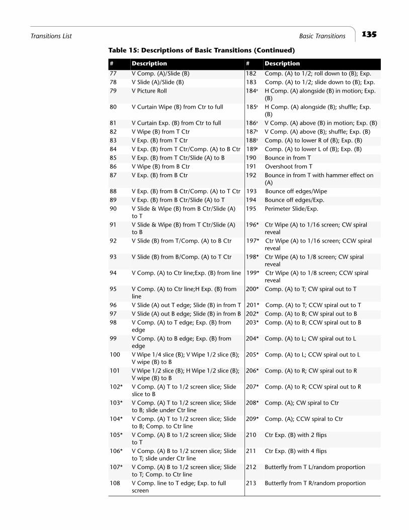
135
Transitions List Basic Transitions
77 V Comp. (A)/Slide (B) 182 Comp. (A) to 1/2; roll down to (B); Exp. 78 V Slide (A)/Slide (B) 183 Comp. (A) to 1/2; slide down to (B); Exp. 79 V Picture Roll 184
#
H Comp. (A) alongside (B) in motion; Exp. (B)
80 V Curtain Wipe (B) from Ctr to full 185
#
H Comp. (A) alongside (B); shuffle; Exp. (B)
81 V Curtain Exp. (B) from Ctr to full 186
#
V Comp. (A) above (B) in motion; Exp. (B)82 V Wipe (B) from T Ctr 187
#
V Comp. (A) above (B); shuffle; Exp. (B)83 V Exp. (B) from T Ctr 188
#
Comp. (A) to lower R of (B); Exp. (B)84 V Exp. (B) from T Ctr/Comp. (A) to B Ctr 189
#
Comp. (A) to lower L of (B); Exp. (B)85 V Exp. (B) from T Ctr/Slide (A) to B 190 Bounce in from T86 V Wipe (B) from B Ctr 191 Overshoot from T87 V Exp. (B) from B Ctr 192 Bounce in from T with hammer effect on
(A)88 V Exp. (B) from B Ctr/Comp. (A) to T Ctr 193 Bounce off edges/Wipe89 V Exp. (B) from B Ctr/Slide (A) to T 194 Bounce off edges/Exp.90 V Slide & Wipe (B) from B Ctr/Slide (A)
to T195 Perimeter Slide/Exp.
91 V Slide & Wipe (B) from T Ctr/Slide (A) to B
196* Ctr Wipe (A) to 1/16 screen; CW spiral reveal
92 V Slide (B) from T/Comp. (A) to B Ctr 197* Ctr Wipe (A) to 1/16 screen; CCW spiral reveal
93 V Slide (B) from B/Comp. (A) to T Ctr 198* Ctr Wipe (A) to 1/8 screen; CW spiral reveal
94 V Comp. (A) to Ctr line;Exp. (B) from line 199* Ctr Wipe (A) to 1/8 screen; CCW spiral reveal
95 V Comp. (A) to Ctr line;H Exp. (B) from line
200* Comp. (A) to T; CW spiral out to T
96 V Slide (A) out T edge; Slide (B) in from T 201* Comp. (A) to T; CCW spiral out to T97 V Slide (A) out B edge; Slide (B) in from B 202* Comp. (A) to B; CW spiral out to B98 V Comp. (A) to T edge; Exp. (B) from
edge203* Comp. (A) to B; CCW spiral out to B
99 V Comp. (A) to B edge; Exp. (B) from edge
204* Comp. (A) to L; CW spiral out to L
100 V Wipe 1/4 slice (B); V Wipe 1/2 slice (B); V wipe (B) to B
205* Comp. (A) to L; CCW spiral out to L
101 V Wipe 1/2 slice (B); H Wipe 1/2 slice (B); V wipe (B) to B
206* Comp. (A) to R; CW spiral out to R
102* V Comp. (A) T to 1/2 screen slice; Slide slice to B
207* Comp. (A) to R; CCW spiral out to R
103* V Comp. (A) T to 1/2 screen slice; Slide to B; slide under Ctr line
208* Comp. (A); CW spiral to Ctr
104* V Comp. (A) T to 1/2 screen slice; Slide to B; Comp. to Ctr line
209* Comp. (A); CCW spiral to Ctr
105* V Comp. (A) B to 1/2 screen slice; Slide to T
210 Ctr Exp. (B) with 2 flips
106* V Comp. (A) B to 1/2 screen slice; Slide to T; slide under Ctr line
211 Ctr Exp. (B) with 4 flips
107* V Comp. (A) B to 1/2 screen slice; Slide to T; Comp. to Ctr line
212 Butterfly from T L/random proportion
108 V Comp. line to T edge; Exp. to full screen
213 Butterfly from T R/random proportion
Table 15: Descriptions of Basic Transitions (Continued)
# Description # Description
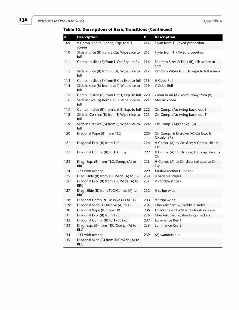
136
Videonics MXPro User Guide Appendix A
109 V Comp. line to B edge; Exp. to full screen
214 Fly-in from T L/fixed proportion
110 Slide in slice (B) from L Ctr; Wipe slice to full
215 Fly-in from T R/fixed proportion
111 Comp. in slice (B) from L Ctr; Exp. to full 216 Random Sizes & Flips (B); fills screen at end
112 Slide in slice (B) from R Ctr; Wipe slice to full
217 Random Wipes (B); Ctr wipe to full screen
113 Comp. in slice (B) from R Ctr; Exp. to full 218 H Cube Roll114 Slide in slice (B) from L at T; Wipe slice to
full219 V Cube Roll
115 Comp. in slice (B) from L at T; Exp. to full 220 Zoom in on (A); zoom away from (B)116 Slide in slice (B) from L at B; Wipe slice to
full221
#
Mosaic Zoom
117 Comp. in slice (B) from L at B; Exp. to full 222 Ctr Comp. (A); swing back; out B118 Slide in Ctr slice (B) from T; Wipe slice to
full223 Ctr Comp. (A); swing back; out T
119 Slide in Ctr slice (B) from B; Wipe slice to full
224
#
Ctr Comp. (A);Ctr Exp. (B)
120 Diagonal Wipe (B) from TLC 225
#
Ctr Comp. & Dissolve (A);Ctr Exp. & Dissolve (B)
121 Diagonal Exp. (B) from TLC 226 H Comp. (A) to Ctr slice; V Comp. slice to Ctr.
122 Diagonal Comp. (B) to TLC; Exp. 227 V Comp. (A) to Ctr slice; H Comp. slice to Ctr.
123 Diag. Exp. (B) from TLC/Comp. (A) to BRC
228 H Comp. (A) to Ctr slice; collapse to Ctr; Exp.
124 123 with overlap 229 Multi-direction Cube roll125 Diag. Slide (B) from TLC/Slide (A) to BRC 230 H variable stripes126 Diagonal Exp. (B) from TLC/Slide (A) to
BRC231 V variable stripes
127 Diag. Slide (B) from TLC/Comp. (A) to BRC
232 H stripe-wipe
128* Diagonal Comp. & Dissolve (A) to TLC 233 V stripe-wipe129* Diagonal Slide & Dissolve (A) to TLC 234 Checkerboard w/middle dissolve130 Diagonal Wipe (B) from TRC 235 Checkerboard w/start to finish dissolve131 Diagonal Exp. (B) from TRC 236 Checkerboard w/shrinking checkers132 Diagonal Comp. (B) to TRC; Exp. 237 Luminance Key 1133 Diag. Exp. (B) from TRC/Comp. (A) to
BLC238 Luminance Key 2
134 133 with overlap 239 (A) wanders out135 Diagonal Slide (B) from TRC/Slide (A) to
BLC
Table 15: Descriptions of Basic Transitions (Continued)
# Description # Description
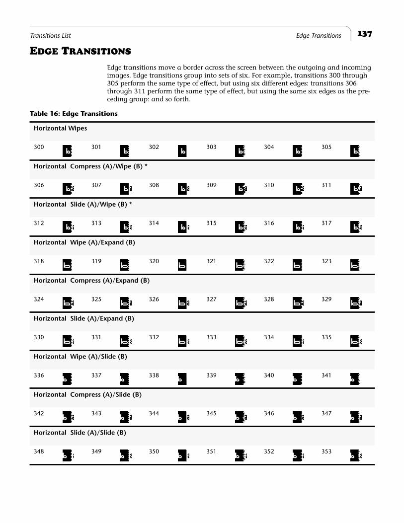
137
Transitions List Edge Transitions
E
DGE
T
RANSITIONS
Edge transitions move a border across the screen between the outgoing and incoming images. Edge transitions group into sets of six. For example, transitions 300 through 305 perform the same type of effect, but using six different edges: transitions 306 through 311 perform the same type of effect, but using the same six edges as the pre-ceding group: and so forth.
Table 16: Edge Transitions
Horizontal Wipes
300 301 302 303 304 305
Horizontal Compress (A)/Wipe (B) *
306 307 308 309 310 311
Horizontal Slide (A)/Wipe (B) *
312 313 314 315 316 317
Horizontal Wipe (A)/Expand (B)
318 319 320 321 322 323
Horizontal Compress (A)/Expand (B)
324 325 326 327 328 329
Horizontal Slide (A)/Expand (B)
330 331 332 333 334 335
Horizontal Wipe (A)/Slide (B)
336 337 338 339 340 341
Horizontal Compress (A)/Slide (B)
342 343 344 345 346 347
Horizontal Slide (A)/Slide (B)
348 349 350 351 352 353
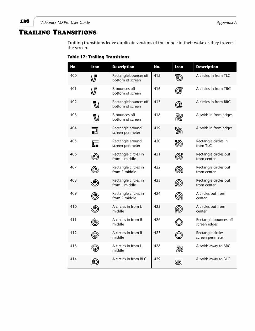
138
Videonics MXPro User Guide Appendix A
T
RAILING
T
RANSITIONS
Trailing transitions leave duplicate versions of the image in their wake as they traverse the screen.
Table 17: Trailing Transitions
No. Icon Description No. Icon Description
400 Rectangle bounces off bottom of screen
415 A circles in from TLC
401 B bounces off bottom of screen
416 A circles in from TRC
402 Rectangle bounces off bottom of screen
417 A circles in from BRC
403 B bounces off bottom of screen
418 A twirls in from edges
404 Rectangle around screen perimeter
419 A twirls in from edges
405 Rectangle around screen perimeter
420 Rectangle circles in from TLC
406 Rectangle circles in from L middle
421 Rectangle circles out from center
407 Rectangle circles in from R middle
422 Rectangle circles out from center
408 Rectangle circles in from L middle
423 Rectangle circles out from center
409 Rectangle circles in from R middle
424 A circles out from center
410 A circles in from L middle
425 A circles out from center
411 A circles in from R middle
426 Rectangle bounces off screen edges
412 A circles in from R middle
427 Rectangle circles screen perimeter
413 A circles in from L middle
428 A twirls away to BRC
414 A circles in from BLC 429 A twirls away to BLC
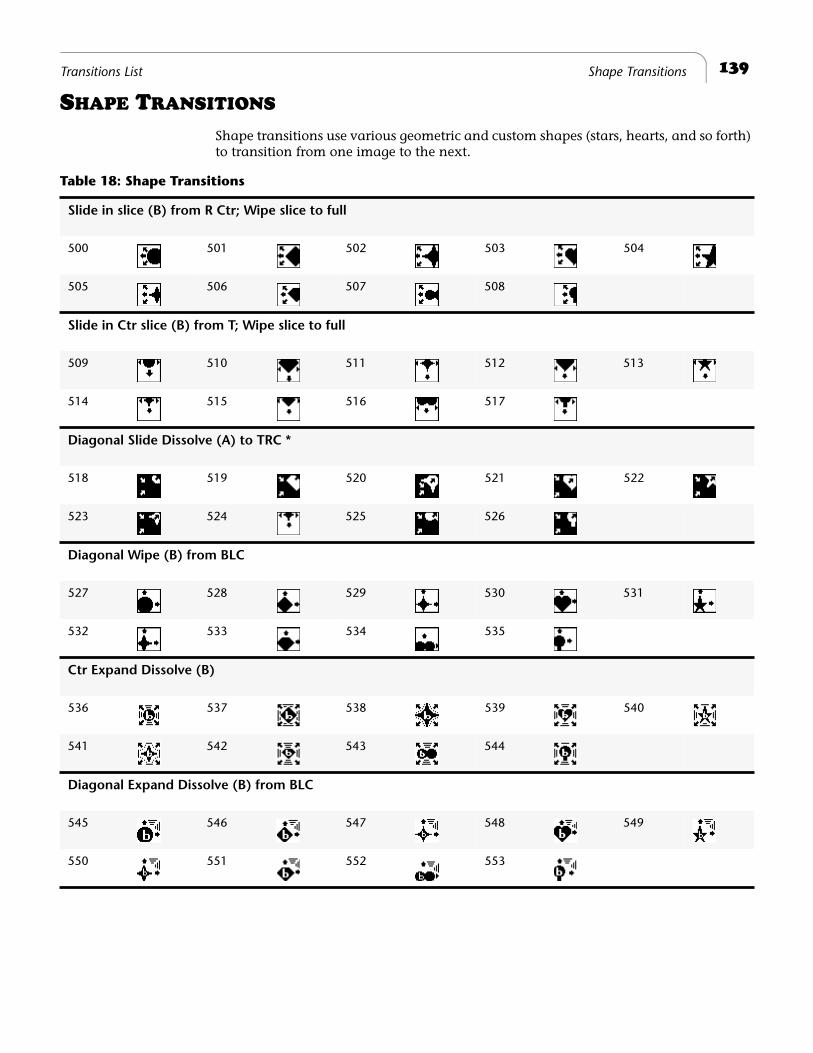
139
Transitions List Shape Transitions
S
HAPE
T
RANSITIONS
Shape transitions use various geometric and custom shapes (stars, hearts, and so forth) to transition from one image to the next.
Table 18: Shape Transitions
Slide in slice (B) from R Ctr; Wipe slice to full
500 501 502 503 504
505 506 507 508
Slide in Ctr slice (B) from T; Wipe slice to full
509 510 511 512 513
514 515 516 517
Diagonal Slide Dissolve (A) to TRC *
518 519 520 521 522
523 524 525 526
Diagonal Wipe (B) from BLC
527 528 529 530 531
532 533 534 535
Ctr Expand Dissolve (B)
536 537 538 539 540
541 542 543 544
Diagonal Expand Dissolve (B) from BLC
545 546 547 548 549
550 551 552 553
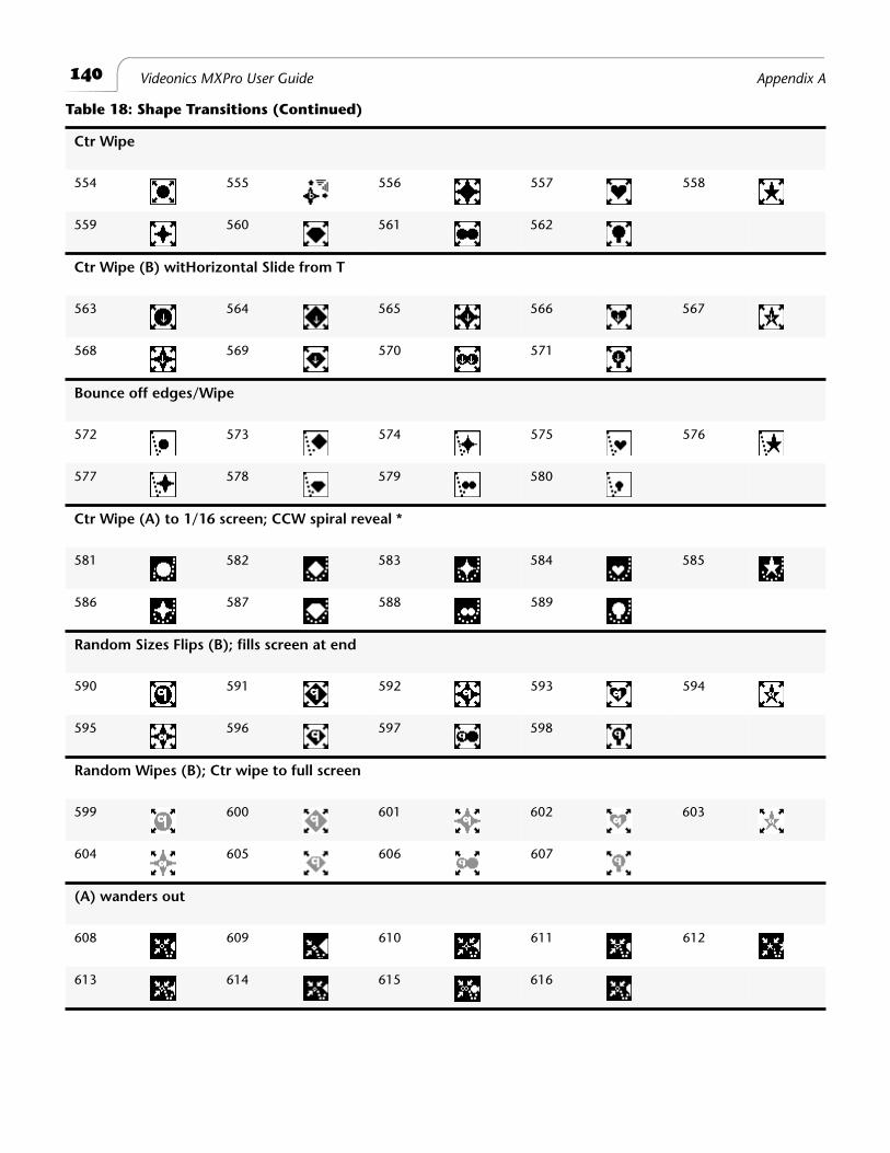
140
Videonics MXPro User Guide Appendix A
Ctr Wipe
554 555 556 557 558
559 560 561 562
Ctr Wipe (B) witHorizontal Slide from T
563 564 565 566 567
568 569 570 571
Bounce off edges/Wipe
572 573 574 575 576
577 578 579 580
Ctr Wipe (A) to 1/16 screen; CCW spiral reveal *
581 582 583 584 585
586 587 588 589
Random Sizes Flips (B); fills screen at end
590 591 592 593 594
595 596 597 598
Random Wipes (B); Ctr wipe to full screen
599 600 601 602 603
604 605 606 607
(A) wanders out
608 609 610 611 612
613 614 615 616
Table 18: Shape Transitions (Continued)
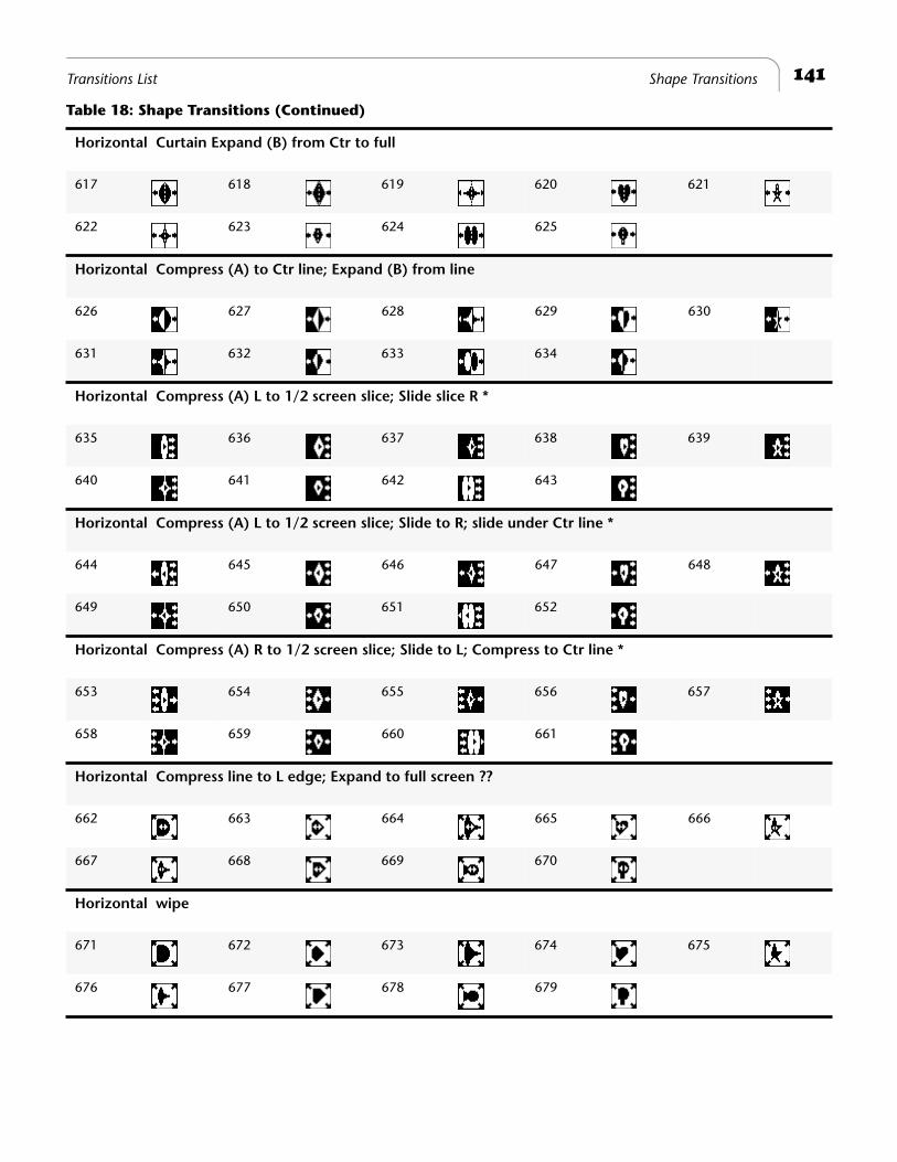
141
Transitions List Shape Transitions
Horizontal Curtain Expand (B) from Ctr to full
617 618 619 620 621
622 623 624 625
Horizontal Compress (A) to Ctr line; Expand (B) from line
626 627 628 629 630
631 632 633 634
Horizontal Compress (A) L to 1/2 screen slice; Slide slice R *
635 636 637 638 639
640 641 642 643
Horizontal Compress (A) L to 1/2 screen slice; Slide to R; slide under Ctr line *
644 645 646 647 648
649 650 651 652
Horizontal Compress (A) R to 1/2 screen slice; Slide to L; Compress to Ctr line *
653 654 655 656 657
658 659 660 661
Horizontal Compress line to L edge; Expand to full screen ??
662 663 664 665 666
667 668 669 670
Horizontal wipe
671 672 673 674 675
676 677 678 679
Table 18: Shape Transitions (Continued)
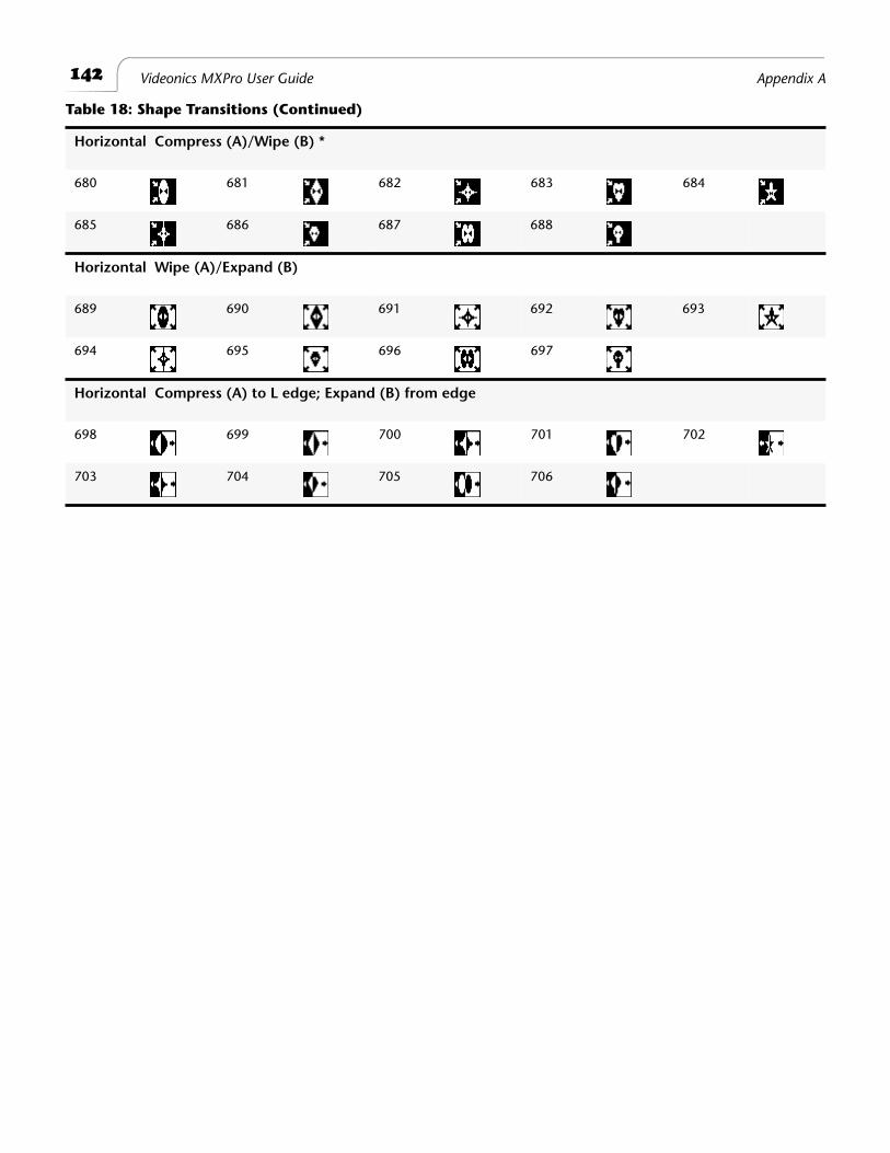
142 Videonics MXPro User Guide Appendix A
Horizontal Compress (A)/Wipe (B) *
680 681 682 683 684
685 686 687 688
Horizontal Wipe (A)/Expand (B)
689 690 691 692 693
694 695 696 697
Horizontal Compress (A) to L edge; Expand (B) from edge
698 699 700 701 702
703 704 705 706
Table 18: Shape Transitions (Continued)

143Transitions List Default User Transitions
DEFAULT USER TRANSITIONS
The User Transitions category contains a default set of transitions compiled from the other categories. You can tailor the User category to your particular needs — see “Changing User Transitions Menu” beginning on page 54.

®
Notes
B
Time Base Corrector
T
he MXPro contains a
T
ime
B
ase
C
orrector (TBC) that ensures top quality results in your productions. The TBC operates automatically at all times. You don’t have to do anything special to use the feature.
TBC compensates for image “shifting” and “wavering” that occurs with many VCR’s, camcorders, and other video devices. It modifies the video signal so that all elements in the picture — lines, fields, frames, and individual dots (or, pixels) — appear on the OUTPUT screen exactly where they should. This improves video signal quality significantly.
D
UAL
TBC M
ODE
You can use the MXPro TBC as a dedicated, two-channel device to induce time base correction on two separate channels. Set up your equipment as follows:
1
Set up the video devices normally — that is, make one the CURRENT source and make another the NEXT source.
2
Press
DISPLAY
so that the Preview screen shows the NEXT source. (See “Display” beginning on page 73 for instructions.)
The CURRENT source appears on the Output monitor. So the two sources each appear on separate monitors, and both have the benefit of time base correction.
While operating in Dual TBC Mode, MXPro can perform cut transitions as it normally does. Use the
CUT
buttons to change the CURRENT source — the one displayed on the Output screen. Use the
NEXT
buttons to choose the NEXT source — which appears on the Preview screen.
146
Videonics MXPro User Guide Appendix B
V
ERTICAL
I
NTERVAL
D
ATA
Time code, closed captioning, and other data in the vertical interval should be added after mixing (downstream from MXPro). This is necessary because dissolves and other transitions mix the data signals, making them unreadable. The MXPro might remove vertical interval data from the sources, depending on how data has been added and the accuracy of a source’s time base.
TBC T
ECHNICAL
I
NFORMATION
The following information might be useful to video technicians.
• MXPro’s TBC has no control options. MXPro always applies TBC to the entire sig-nal, including the horizontal and vertical intervals.
• MXPro provides a dual-field TBC to correct two sources at the same time. Because all transitions and effects use only two of the four sources at any given time, the dual field TBC can correct the time base of the entire output signal, transitions and all.
• The output sync of the TBC is independent of all inputs. There is no way to syn-chronize it with an external sync or with any of the inputs.
C
Video Quality
MXPro meets the highest video quality standards. However, video artifacts can appear in video productions, especially when you use sophisticated effects and transitions. This appendix describes some of the video artifacts that can occur.
Note
The situations and artifacts discussed in this appendix normally apply to advanced
video concepts. They might, therefore, be of interest only to a selected audience.
P
REVIEW
I
MAGE
Q
UALITY
Images appearing on the MXPro Preview screen do not represent MXPro’s true quality because they serve only as a representation of the images. Furthermore, the images do not show input effects or the results of advanced setup options. Depending on the type of devices attached, you might occasionally see lines along the sides of the preview images. This is especially noticeable when using cue or review (search) with a VCR or camcorder attached to an input jack, using poor quality video tapes, experiencing bad reception, and so forth. In such cases, you might be able to improve video quality using one or more of the following methods:
• Use only high-quality video sources.
• When using a camcorder or VCR with an Edit switch, turn the switch On to dis-able playback processing circuits.
• Turn Off any sharpness controls and enhancement circuits.
Preview image quality does not affect video output quality.
You can switch to a full-size, full frame-rate version of the NEXT or CURRENT source at any time using the
DISPLAY
button. See “Display” beginning on page 73 to learn about all of the display options.
148
Videonics MXPro User Guide Appendix C
V
IDEO
S
CALING
A
RTIFACTS
Reducing a video image’s size can create artifacts because some picture information must be discarded to reduce the number of pixels in the image. In some cases, picture information might disappear when eliminating pixels. For example, lines in the image might appear jagged when MXPro removes pixels and, therefore, parts of the line.
Some MXPro transitions scale an image down gradually. This might cause small fea-tures to appear and disappear as the image scales down.
The artifacts described here are normal when performing advanced effects. They are normally minor when running transitions at normal speeds.
F
REEZE
Q
UALITY
You can set MXPro to freeze either a frame or a field (see “Force Field Freeze” on page 76).
Freeze Field
captures one field (half a video frame) and duplicates it to make the two fields that comprise a frame. This eliminates flashing caused when an object occupies a different position in the two captured fields, or when an object is so small it appear in only one field. MXPro’s Field Freeze eliminates flashing artifacts but reduces vertical resolution because it shows only one field.
Freeze Frame
captures all fields in the image. This produces a higher quality image, but some flashing might occur.
U
PSIDE
-D
OWN
V
IDEO
When you flip video upside-down (as occurs automatically with some transitions and when using the Flip (vertical) option on the
INPUT EFFECTS
menu), the picture resolu-tion reduces slightly and the frame rate also reduces to make the video image more stable. The reduction is subtle with most video and most effects, especially those that move quickly.
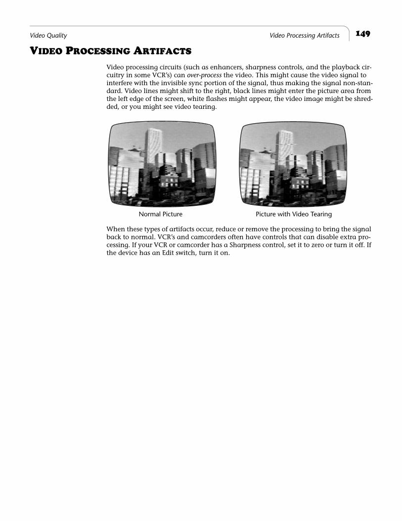
149
Video Quality Video Processing Artifacts
V
IDEO
P
ROCESSING
A
RTIFACTS
Video processing circuits (such as enhancers, sharpness controls, and the playback cir-cuitry in some VCR’s) can
over-process
the video. This might cause the video signal to interfere with the invisible sync portion of the signal, thus making the signal non-stan-dard. Video lines might shift to the right, black lines might enter the picture area from the left edge of the screen, white flashes might appear, the video image might be shred-ded, or you might see video tearing.
When these types of artifacts occur, reduce or remove the processing to bring the signal back to normal. VCR’s and camcorders often have controls that can disable extra pro-cessing. If your VCR or camcorder has a Sharpness control, set it to zero or turn it off. If the device has an Edit switch, turn it on.
Normal Picture Picture with Video Tearing

®
Notes
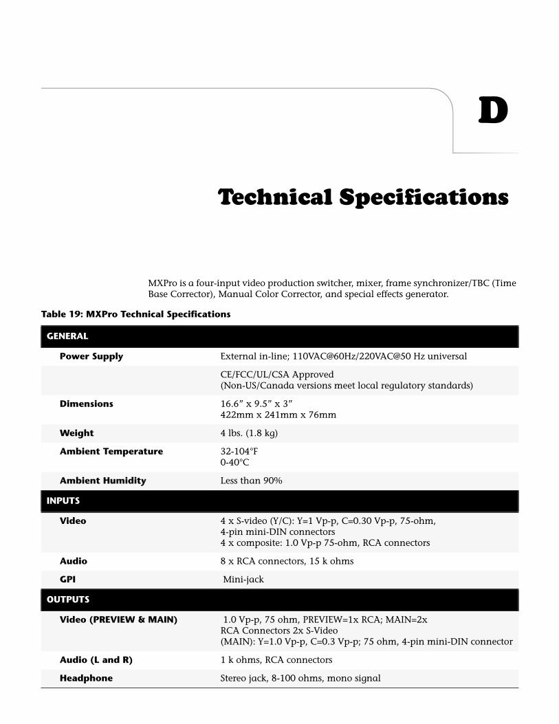
D
Technical Specifications
MXPro is a four-input video production switcher, mixer, frame synchronizer/TBC (Time Base Corrector), Manual Color Corrector, and special effects generator.
Table 19: MXPro Technical Specifications
GENERAL
Power Supply
External in-line; 110VAC@60Hz/220VAC@50 Hz universal
CE/FCC/UL/CSA Approved (Non-US/Canada versions meet local regulatory standards)
Dimensions
16.6” x 9.5” x 3” 422mm x 241mm x 76mm
Weight
4 lbs. (1.8 kg)
Ambient Temperature
32-104
°
F0-40
°
C
Ambient Humidity
Less than 90%
INPUTS
Video
4 x S-video (Y/C): Y=1 Vp-p, C=0.30 Vp-p, 75-ohm, 4-pin mini-DIN connectors 4 x composite: 1.0 Vp-p 75-ohm, RCA connectors
Audio
8 x RCA connectors, 15 k ohms
GPI
Mini-jack
OUTPUTS
Video (PREVIEW & MAIN)
1.0 Vp-p, 75 ohm, PREVIEW=1x RCA; MAIN=2x RCA Connectors 2x S-Video (MAIN): Y=1.0 Vp-p, C=0.3 Vp-p; 75 ohm, 4-pin mini-DIN connector
Audio (L and R)
1 k ohms, RCA connectors
Headphone
Stereo jack, 8-100 ohms, mono signal
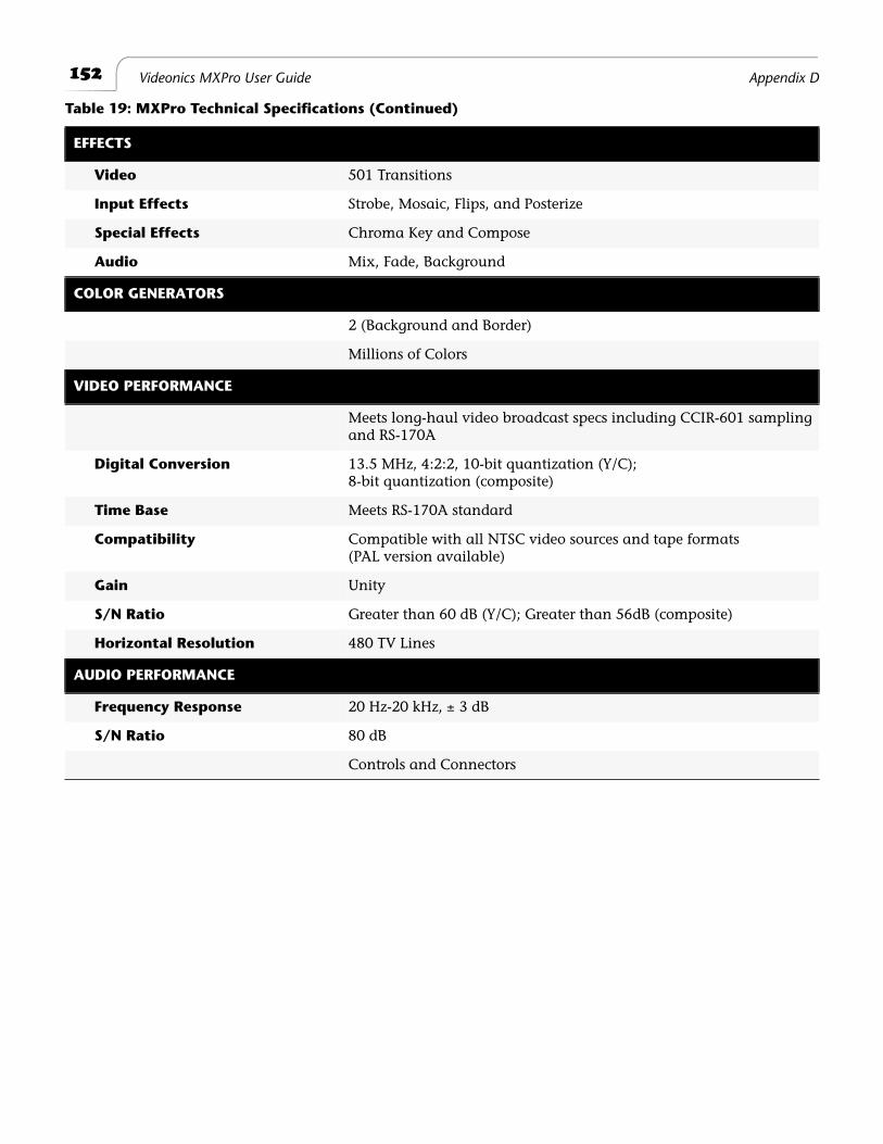
152
Videonics MXPro User Guide Appendix D
EFFECTS
Video
501 Transitions
Input Effects
Strobe, Mosaic, Flips, and Posterize
Special Effects
Chroma Key and Compose
Audio
Mix, Fade, Background
COLOR GENERATORS
2 (Background and Border)
Millions of Colors
VIDEO PERFORMANCE
Meets long-haul video broadcast specs including CCIR-601 sampling and RS-170A
Digital Conversion
13.5 MHz, 4:2:2, 10-bit quantization (Y/C); 8-bit quantization (composite)
Time Base
Meets RS-170A standard
Compatibility
Compatible with all NTSC video sources and tape formats(PAL version available)
Gain
Unity
S/N Ratio
Greater than 60 dB (Y/C); Greater than 56dB (composite)
Horizontal Resolution
480 TV Lines
AUDIO PERFORMANCE
Frequency Response
20 Hz-20 kHz,
±
3 dB
S/N Ratio
80 dB
Controls and Connectors
Table 19: MXPro Technical Specifications (Continued)
E
Information for MX-1 Users
This appendix helps Videonics MX-1 users make an easy transition to MXPro. It high-lights key operational commands from the MX-1 that have changed with MXPro.
MXPro offers many new features and expands the capability of some MX-1 operations. You won’t be able to enjoy the full benefits of the new features without reading the other chapters in this User Guide.
MXPro Defaults to S-Video on All 4 Channels
If you use one or more Composite-type devices as input, you need to change the settings for those devices on the ROUTE screen. See “Route” beginning on page 77 for instructions.
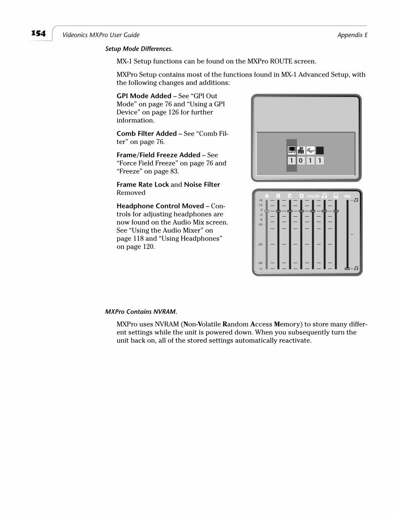
154
Videonics MXPro User Guide Appendix E
Setup Mode Differences.
MX-1 Setup functions can be found on the MXPro ROUTE screen.
MXPro Setup contains most of the functions found in MX-1 Advanced Setup, with the following changes and additions:
GPI Mode Added
– See “GPI Out Mode” on page 76 and “Using a GPI Device” on page 126 for further information.
Comb Filter Added
– See “Comb Fil-ter” on page 76.
Frame/Field Freeze Added
– See “Force Field Freeze” on page 76 and “Freeze” on page 83.
Frame Rate Lock
and
Noise Filter
Removed
Headphone Control Moved
– Con-trols for adjusting headphones are now found on the Audio Mix screen. See “Using the Audio Mixer” on page 118 and “Using Headphones” on page 120.
MXPro Contains NVRAM.
MXPro uses NVRAM (
N
on-
V
olatile
R
andom
A
ccess
M
emory) to store many differ-ent settings while the unit is powered down. When you subsequently turn the unit back on, all of the stored settings automatically reactivate.
1 0 1 1
MIXCOLOR+6
+3
0
-3
-6
-10
-20
-30
-∞
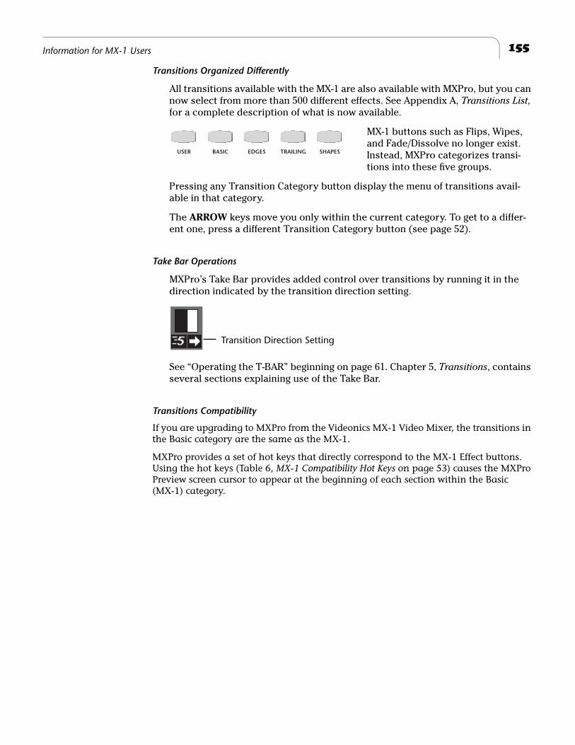
155
Information for MX-1 Users
Transitions Organized Differently
All transitions available with the MX-1 are also available with MXPro, but you can
now select from more than 500 different effects. See Appendix A,
Transitions List
, for a complete description of what is now available.
MX-1 buttons such as Flips, Wipes, and Fade/Dissolve no longer exist. Instead, MXPro categorizes transi-tions into these five groups.
Pressing any Transition Category button display the menu of transitions avail-able in that category.
The
ARROW
keys move you only within the current category. To get to a differ-ent one, press a different Transition Category button (see page 52).
Take Bar Operations
MXPro’s Take Bar provides added control over transitions by running it in the direction indicated by the transition direction setting.
See “Operating the T-BAR” beginning on page 61. Chapter 5,
Transitions
, contains several sections explaining use of the Take Bar.
Transitions Compatibility
If you are upgrading to MXPro from the Videonics MX-1 Video Mixer, the transitions in the Basic category are the same as the MX-1.
MXPro provides a set of hot keys that directly correspond to the MX-1 Effect buttons. Using the hot keys (Table 6,
MX-1 Compatibility Hot Keys
on page 53) causes the MXPro Preview screen cursor to appear at the beginning of each section within the Basic (MX-1) category.
USER BASIC EDGES TRAILING SHAPES
Transition Direction Setting

®
Notes
Glossary
Some terms defined in this glossary might not appear in the body of the User Guide.
A/A Roll
A term originating in the film world. Normally describes rolling a single source into an effects device, such as the Videonics MXPro, and creating transitions between the individual scenes.
A/B Roll
Variation of A/A Roll (described above). Normally describes rolling two or more sources into an effects device, such as the Videonics MXPro, and creating transitions between the various source images.
AV/Net™
A micro controller-based adapter offered by Vide-onics that can be daisy chained. It allows you to control multiple video devices using only one of your computer’s serial ports.
Betacam
An industry standard format that uses half-inch videotape running at high speed to produce high quality video. It is an evolving standard. There are currently three versions in common use: Betacam, Betacam SP, and Digital Betacam.
Camcorder
Combination camera and video recorder in one device. Normally contains video recording heads as well as a video playback unit (that is, a mini-VCR).
Composite Video
The format used by televisions, many VCR’s, and
laser disc players. Also see
S-Video
.
Counter
A relative indicator of tape position. On VCR’s that do not support time code, the tape counter stores scene locations. Because it is a relative indicator of tape position, it is subject to drift. The same tape logged on one VCR and viewed on another might report different counter locations for the same scene.
Deck
A video cassette/tape player or recorder, also called
a
VCR
or
VTR
.
Digital Still Camera
A recording device for taking photographs and storing the information in digital form. The device is similar to a 35mm reflex lens camera that uses traditional film except that it stores the image on a silicon chip. Images can then be
downloaded
to a computer system.
Drop Frame
A variation on the SMPTE time code format. It refers to a scheme designed to compensate for the fact that NTSC actually runs at 29.97 fps. Normal Time Code (or, Non-Drop Frame Time Code) is recorded and calculated based on 30 fps. Because the actual number of frames per second is really 29.97, a discrepancy occurs causing a loss of slightly more than three seconds each hour. Drop frame corrects for this error by skipping two frames every minute, except on the tenth minute.
FPS
F
rames
P
er
S
econd. The number of picture frames that are recorded or played during a one second period. Television nominally uses 29.97 fps (NTSC) or 25 fps (PAL).
Flying Erase Heads
Standard erase heads are mounted along the tape path in a VCR. A flying erase head is built into the video head drum just ahead of the video heads. It makes it possible to erase the video each helical scan at a time resulting in clean video edits with no
rainbow
effect. It is a requirement for high quality video editing.
IR
I
nfra
R
ed is one of several remote control protocols. It is a one way protocol that allows a device to send command to the VCR. Because this is a one-way communication, the VCR cannot send tape loca-tion information back. VCR’s that offer this limited method of control are suitable only as record decks.
LTC
L
ongitudinal
T
ime
C
ode is an SMPTE-defined stan-dard for time code, normally recorded onto a linear audio track of a VCR.
158
Glossary Videonics MXPro User Guide
NTSC
N
ational
T
elevision
S
tandards
C
ommittee. A body that defines television standards in the USA. NTSC is characterized by each frame being composed of 525 horizontal scanning lines per frame, occurring at 30 frames per second. The format is used in North America, Central America, Japan, and parts of South America. (Also see
PAL
and
SECAM
.)
NVRAM
N
on-
V
olatile
R
andom
A
ccess
M
emory. MXPro uses NVRAM to store unit settings so that they are avail-able whenever you power up the unit. Normal (that is, volatile) RAM cannot store information once the power supply is turned off.
OSD
O
n
S
creen
D
isplay. A feature available on some consumer-level VCR’s. When OSD is toggled ON, the VCR displays its status information on the con-nected video monitor.
PAL
P
hase
A
lternating
L
ines. The dominant color tele-vision format in Western Europe, Australia, most of Asia, and parts of South America and Africa. PAL is characterized by each frame being composed of 625 horizontal scanning lines occurring 25 times per second. (Also see
NTSC
and
SECAM
.)
RCTC
R
ewriteable
C
onsumer
T
ime
C
ode (also referred to as
RC
). Commonly available on 8mm and Hi-8 for-mat devices.
S-Video
A video standard used by camcorders and VCR’s relative to video signal formats. S-Video separates the Y (luminance) and C (chroma) signals to improve signal quality. Also see
Composite Video
.
SECAM
The standard video signal used in France, Eastern Europe, and parts of Asia and Africa. Also see
NTSC
and
PAL
.
SMPTE
S
ociety of
M
otion
P
icture and
T
elevision
E
ngi-neers. (Pronounced
simp-tee
.) This committee of engineers and manufacturers establishes the most widely accepted standard for time code. They cre-ated specifications for two version of time code: LTC and VITC.
Time Code
A method of putting a unique number or address on each frame of a videotape. There are several for-mats of time code. The Society of Motion Picture and Television Engineers set the most common time code standard, called SMPTE.
VCR
V
ideo
C
assette
R
ecorder. A video device normally used to record and play back video on cassettes. VCR is a consumer-level term: VCR’s in the profes-sional field are normally referred to as VTR’s (
V
ideo
T
ape
R
ecorders). VCR’s and VTR’s perform the same functions, although VTR’s usually provide many additional features and functions.
Video Editing
The process of applying special effects to video sequences and assembling those sequences into a video program.
VITC
V
ertical
I
nterval
T
ime
C
ode. (Pronounced
vit-see
.) An SMPTE-defined standard for time code, recorded into the video signal during the vertical blanking interval.
VTR
V
ideo
T
ape
R
ecorder. Similar to VCR (see above) except that VTR’s are normally used in the profes-sional video field and contain enhanced features. VCR is normally used in conjunction with con-sumer-level electronics.
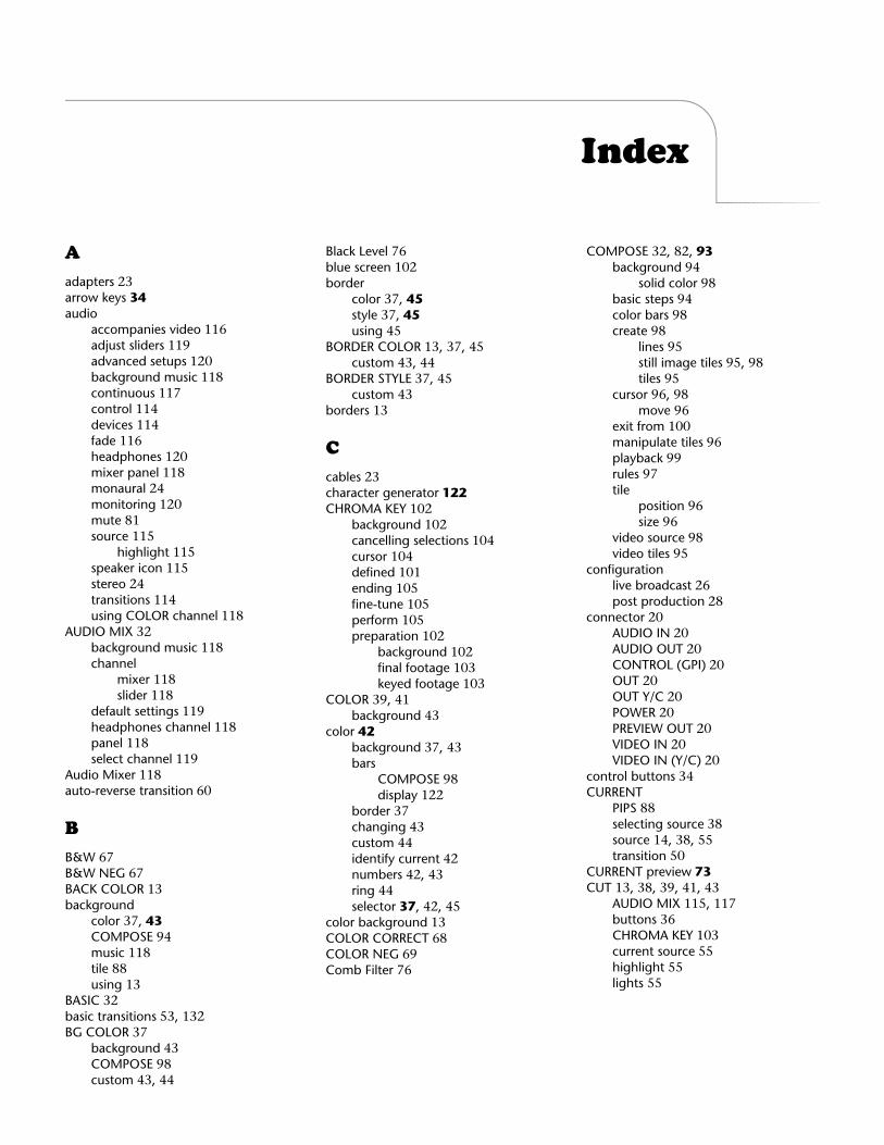
Index
A
adapters
23
arrow keys
34
audioaccompanies video
116
adjust sliders
119
advanced setups
120
background music
118
continuous
117
control
114
devices
114
fade
116
headphones
120
mixer panel
118
monaural
24
monitoring
120
mute
81
source
115
highlight
115
speaker icon
115
stereo
24
transitions
114
using COLOR channel
118
AUDIO MIX
32
background music
118
channelmixer
118
slider
118
default settings
119
headphones channel
118
panel
118
select channel
119
Audio Mixer
118
auto-reverse transition
60
B
B&W
67
B&W NEG
67
BACK COLOR
13
backgroundcolor
37
,
43
COMPOSE
94
music
118
tile
88
using
13
BASIC
32
basic transitions
53
,
132
BG COLOR
37
background
43
COMPOSE
98
custom
43
,
44
Black Level
76
blue screen
102
bordercolor
37
,
45
style
37
,
45
using
45
BORDER COLOR
13
,
37
,
45
custom
43
,
44
BORDER STYLE
37
,
45
custom
43
borders
13
C
cables
23
character generator
122
CHROMA KEY
102
background
102
cancelling selections
104
cursor
104
defined
101
ending
105
fine-tune
105
perform
105
preparation
102
background
102
final footage
103
keyed footage
103
COLOR
39
,
41
background
43
color
42
background
37
,
43
barsCOMPOSE
98
display
122
border
37
changing
43
custom
44
identify current
42
numbers
42
,
43
ring
44
selector
37
,
42
,
45
color background
13
COLOR CORRECT
68
COLOR NEG
69
Comb Filter
76
COMPOSE
32
,
82
,
93background 94
solid color 98basic steps 94color bars 98create 98
lines 95still image tiles 95, 98tiles 95
cursor 96, 98move 96
exit from 100manipulate tiles 96playback 99rules 97tile
position 96size 96
video source 98video tiles 95
configurationlive broadcast 26post production 28
connector 20AUDIO IN 20AUDIO OUT 20CONTROL (GPI) 20OUT 20OUT Y/C 20POWER 20PREVIEW OUT 20VIDEO IN 20VIDEO IN (Y/C) 20
control buttons 34CURRENT
PIPS 88selecting source 38source 14, 38, 55transition 50
CURRENT preview 73CUT 13, 38, 39, 41, 43
AUDIO MIX 115, 117buttons 36CHROMA KEY 103current source 55highlight 55lights 55
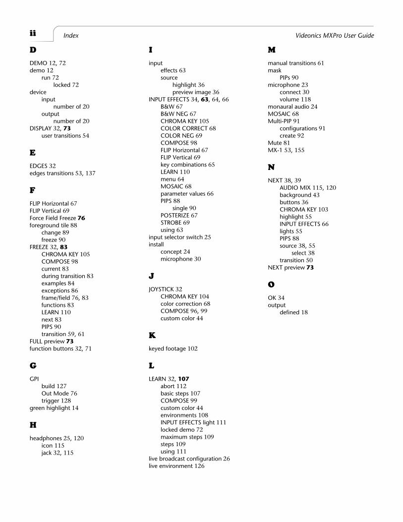
ii Index Videonics MXPro User Guide
D
DEMO 12, 72demo 12
run 72locked 72
deviceinput
number of 20output
number of 20DISPLAY 32, 73
user transitions 54
E
EDGES 32edges transitions 53, 137
F
FLIP Horizontal 67FLIP Vertical 69Force Field Freeze 76foreground tile 88
change 89freeze 90
FREEZE 32, 83CHROMA KEY 105COMPOSE 98current 83during transition 83examples 84exceptions 86frame/field 76, 83functions 83LEARN 110next 83PIPS 90transition 59, 61
FULL preview 73function buttons 32, 71
G
GPIbuild 127Out Mode 76trigger 128
green highlight 14
H
headphones 25, 120icon 115jack 32, 115
I
inputeffects 63source
highlight 36preview image 36
INPUT EFFECTS 34, 63, 64, 66B&W 67B&W NEG 67CHROMA KEY 105COLOR CORRECT 68COLOR NEG 69COMPOSE 98FLIP Horizontal 67FLIP Vertical 69key combinations 65LEARN 110menu 64MOSAIC 68parameter values 66PIPS 88
single 90POSTERIZE 67STROBE 69using 63
input selector switch 25install
concept 24microphone 30
J
JOYSTICK 32CHROMA KEY 104color correction 68COMPOSE 96, 99custom color 44
K
keyed footage 102
L
LEARN 32, 107abort 112basic steps 107COMPOSE 99custom color 44environments 108INPUT EFFECTS light 111locked demo 72maximum steps 109steps 109using 111
live broadcast configuration 26live environment 126
M
manual transitions 61mask
PIPs 90microphone 23
connect 30volume 118
monaural audio 24MOSAIC 68Multi-PIP 91
configurations 91create 92
Mute 81MX-1 53, 155
N
NEXT 38, 39AUDIO MIX 115, 120background 43buttons 36CHROMA KEY 103highlight 55INPUT EFFECTS 66lights 55PIPS 88source 38, 55
select 38transition 50
NEXT preview 73
O
OK 34output
defined 18
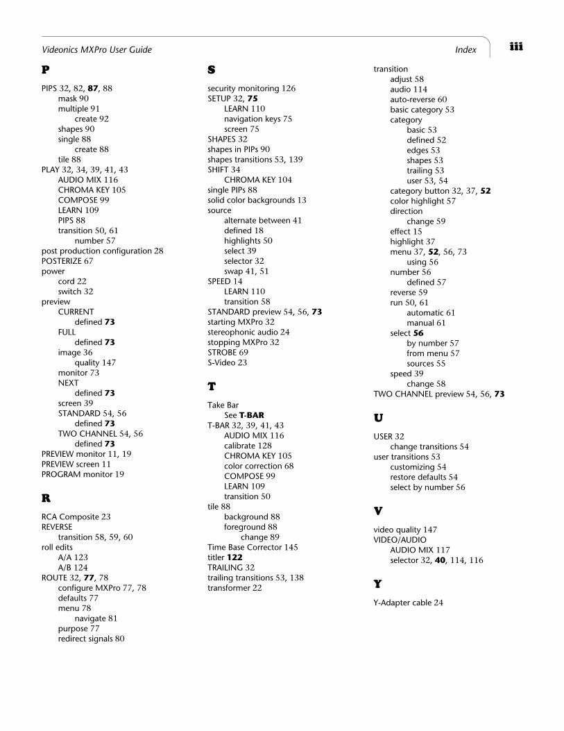
iiiVideonics MXPro User Guide Index
P
PIPS 32, 82, 87, 88mask 90multiple 91
create 92shapes 90single 88
create 88tile 88
PLAY 32, 34, 39, 41, 43AUDIO MIX 116CHROMA KEY 105COMPOSE 99LEARN 109PIPS 88transition 50, 61
number 57post production configuration 28POSTERIZE 67power
cord 22switch 32
previewCURRENT
defined 73FULL
defined 73image 36
quality 147monitor 73NEXT
defined 73screen 39STANDARD 54, 56
defined 73TWO CHANNEL 54, 56
defined 73PREVIEW monitor 11, 19PREVIEW screen 11PROGRAM monitor 19
R
RCA Composite 23REVERSE
transition 58, 59, 60roll edits
A/A 123A/B 124
ROUTE 32, 77, 78configure MXPro 77, 78defaults 77menu 78
navigate 81purpose 77redirect signals 80
S
security monitoring 126SETUP 32, 75
LEARN 110navigation keys 75screen 75
SHAPES 32shapes in PIPs 90shapes transitions 53, 139SHIFT 34
CHROMA KEY 104single PIPs 88solid color backgrounds 13source
alternate between 41defined 18highlights 50select 39selector 32swap 41, 51
SPEED 14LEARN 110transition 58
STANDARD preview 54, 56, 73starting MXPro 32stereophonic audio 24stopping MXPro 32STROBE 69S-Video 23
T
Take BarSee T-BAR
T-BAR 32, 39, 41, 43AUDIO MIX 116calibrate 128CHROMA KEY 105color correction 68COMPOSE 99LEARN 109transition 50
tile 88background 88foreground 88
change 89Time Base Corrector 145titler 122TRAILING 32trailing transitions 53, 138transformer 22
transitionadjust 58audio 114auto-reverse 60basic category 53category
basic 53defined 52edges 53shapes 53trailing 53user 53, 54
category button 32, 37, 52color highlight 57direction
change 59effect 15highlight 37menu 37, 52, 56, 73
using 56number 56
defined 57reverse 59run 50, 61
automatic 61manual 61
select 56by number 57from menu 57sources 55
speed 39change 58
TWO CHANNEL preview 54, 56, 73
U
USER 32change transitions 54
user transitions 53customizing 54restore defaults 54select by number 56
V
video quality 147VIDEO/AUDIO
AUDIO MIX 117selector 32, 40, 114, 116
Y
Y-Adapter cable 24

®
Notes