Embed Size (px)
Citation preview
PROJECT NEWS SPECIAL
Steve Kember continues the story of the build of his Mission 108, G-STPK at the company’s facility in Belgium
14 LIGHT AVIATION | MARCH 2014
M I S S I O N 1 0 8
Pr ject News Special
This chapter concentrates on the instrument panel and avionics that, with Filip Lambert’s expertise, is a quite
sophisticated package.I used to fly with a highly regarded, now
retired, flying instructor of the old school. You know the sort, thousands of hours in his log book with more aircraft types flown than I’ve had hot dinners. He used to tell stories of how he used to fly over central London in a Tiger Moth at 10,000ft and was able to look down into the grounds of Buckingham Palace. No fuss, just flying at its spiritual and tactile best. Certainly the idea of bimbling about, non-radio, minimum instruments, and just a map and a watch is very appealing, but in the crowded skies of South East England however, those days have long gone.
For me though, that free and relaxed approach to flying can be partly restored using a bit of modern technology. When I fly club aircraft (PA-28 or C172 in my case) I like to have a small, portable GPS gently glowing on the yoke mount to confirm that I am actually where I think I am. I can use the radio to check that the café at my intended destination is still open and to announce my arrival and the transponder gives me the option to fly in more controlled airspace. Le Touquet for lunch, perhaps. The fun and the freedom is still there
– it just has to be managed differently. The constraints of ever more regulated
airspace can, to some extent, be counter-balanced by some of the marvellous technology that is available. And it can be relatively inexpensive and easy to use; just how easy has recently become something of a revelation. I had no idea how integrated an up-to-date panel can be.
The choice of engine for my Lambert Mission M108, the Rotax 912iS, can only be operated with a compatible electronic display as the familiar ‘steam age’ instruments will not work, so it has to be a glass cockpit. The engine is fuel injected, therefore no carb icing problems and no need to lean the mixture – it is done automatically by the ECU. “Ah ha,” I hear some of you say, “ECUs can be trouble.” Well, having spent half of my 36-year/750,000 mile driving career using cars with ECUs and fuel injection, I can honestly say I have never had a problem with car engine management systems, not one. I’ve had a few issues with carburettors though.
So why should my aircraft be any different? Time will tell. Another benefit of fitting the injected Rotax, is that it comes with diagnostic software (BUDS), which is a convenient tool for maintenance and troubleshooting. It will allow me to connect my laptop to the ECU to download a log of any errors that have occurred or any limits that may have been exceeded. This practice has been standard for car maintenance for more than a decade.
The instruments on my panel will include the TL Elektronic Integra 6624 Primary Flight Display (PFD), Electronic Flight Instrument System (EFIS) and Engine Monitoring System (EMS). A Garmin 795 GPS, a Trig TT21 mode S transponder and a Trig TY91 8.33kHz radio. The stand-by instrument, the LX Navigation BU57, consists of three instruments in one; the altimeter, airspeed indicator and rate of climb indicator are all combined to save space and will be fitted, subject to LAA approval. This combination of instruments was chosen for maximum value for money and functionality. More on how they interact later.
The panel was originally conceived by Filip Lambert. It is well thought out, and contains features that will make maintenance and everyday life for the pilot/owner, easy and straightforward. A ‘power-in’ socket has been incorporated into the circuitry and may be
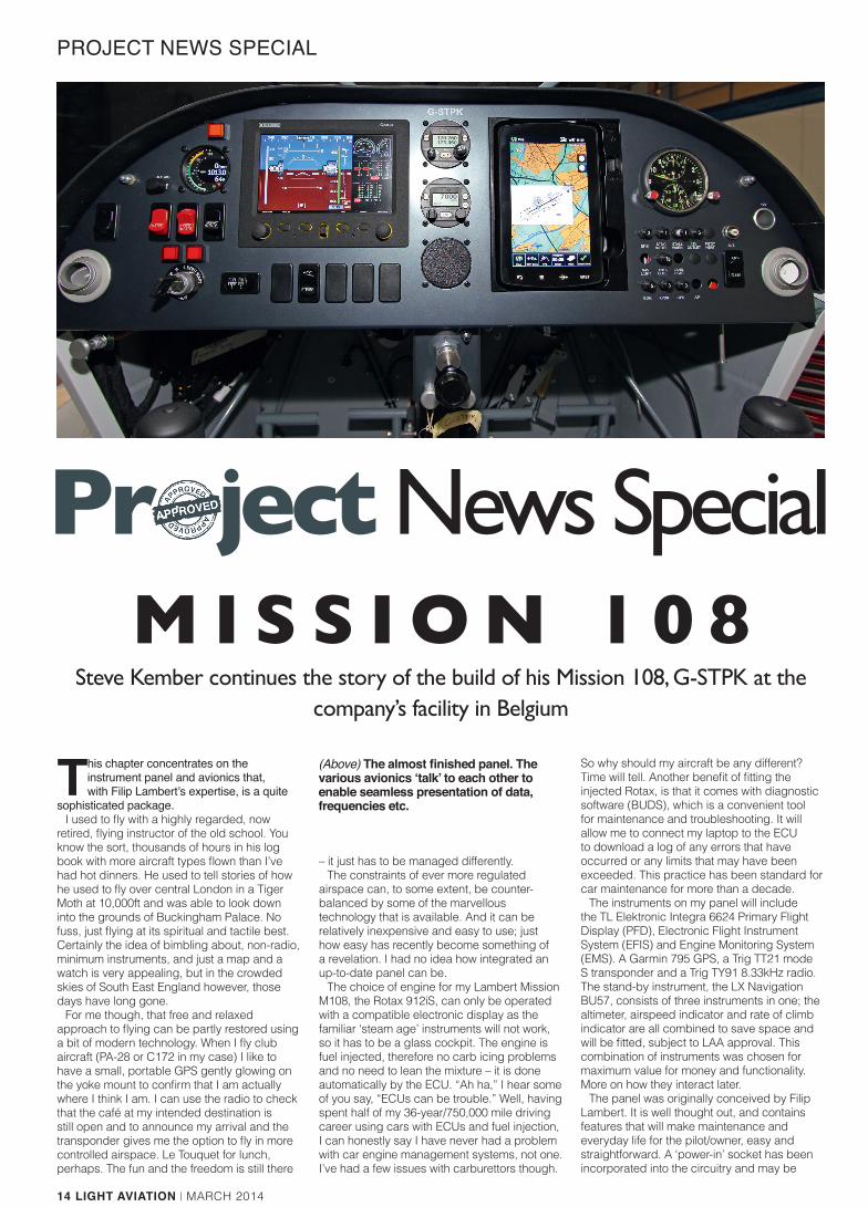
(Above) The almost finished panel. The various avionics ‘talk’ to each other to enable seamless presentation of data, frequencies etc.
LA3.projectnews special.v3.EE..indd 14 24/02/2014 15:57
MARCH 2013 | LIGHT AVIATION 15
PROJECT NEWS SPECIAL
Pr ject News Specialaccessed under the panel. Using this socket to connect an external power source will have several benefits; it will provide power to the aircraft’s electrical system without draining the battery: software can be upgraded; aircraft maintenance is made easier; and it can be used to trickle charge the aircraft battery. The use of the socket will eliminate the hazards involved using crocodile clips (short circuits). The circuitry protects against over voltage and reverse polarity. However, this socket cannot be used to ‘jump-start’ the engine should the main aircraft battery be flat.
Another useful feature is that the panel has what Filip calls a ‘clearance’ switch. This will enable radio calls to be made and allow GPS programming prior to engine start with minimal drain of the aircraft battery. For engine start, the clearance switch is moved to the ‘off’ position, the engine is started and away you go. The check lists may be stored in the document folder of the Garmin, all easily updated via a memory card that slots in the side, just like the one in a digital camera.
The panel may be removed quickly if required. The procedure is as follows: unplug the two cables from the engine to the TL-6624 (marked HICA and HICB), disconnect power and data plugs and then the pitot tubes. The pitot tubes have quick release and attach fittings (Cirrus uses similar connectors on the back of the Avidyne PFD), see photos. Undo the four bolts holding the panel via shock mounts to the fuselage – job done! It takes ten minutes, tops.
Each one of the instruments on my panel is capable of doing some pretty impressive things. Let us start with the TL Elektronic TL-6624, which has a variety of screen options. The one I expect to use most of the time is the split screen showing flight instruments to the left and engine instruments to the right.
As mentioned in a previous instalment of the build, my radio choice is the future proofed Trig TY91 with 8.33kHz channel spacing. This unit comes in two parts, the control head which you see on the panel, and the actual transceiver which sits on the avionics shelf (which sits between the panel facia and the engine firewall, see picture). I will be able to store nine different frequencies in this radio and monitor
GLOSSARYBUDS: This stands for BRP Utility and Diagnostic Software (BRP = Bombardier Recreational Products). A useful program to install on a laptop as an aid to maintenance CAN-BUS: CAN or Controller Area Network is the system or standard that allows high-speed data transfer between two or more electronic devices. The system was first developed by Bosch and was used to great effect to reduce the quantity of cable used in automotive electrical systems. The bus is the physical connection of all of the individual components, i.e. pieces of wire. RS-232: Another system (or language) used to allow electronic devices to communicate.Serial port: The physical connection through which information travels in and out of a system or device.
ECU: Engine Control UnitSquitter: The unsolicited broadcasting of data by a Mode S transponder. Mode S transponders squitter, on average once per second. In addition to squittering, a Mode S transponder will also reply to Mode A, C or S interrogations from ground radar or air traffic collision avoidance systems.Extended squitter: A squitter mode in which additional data is broadcast such as GPS position, track and ground speed. This information can be received by airborne traffic systems to display the position of nearby aircraft. As I understand from Filip, he is planning to offer a traffic receiver for the Mission M108 in the next few months. With this receiver, it will be possible to see the position of other suitably equipped aircraft on the display of the Garmin 795.
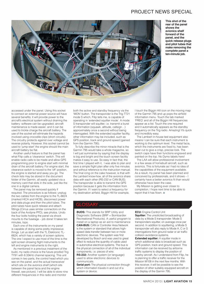
This shot of the rear of the panel shows the avionics shelf forward of the panel, and the quick release plugs and pitot tubes that make removing the complete panel a ten-minute job.
both the active and standby frequency via the ‘MON’ button. The transponder is the Trig TT21 mode S which, Filip tells me, is capable of operating in ‘extended squitter mode’. A mode S transponder will squitter, i.e. transmit a burst of information (squawk, altitude, callsign…) approximately once a second without being interrogated. With the extended squitter facility, other information may be included, such as GPS position, track and ground speed (gained from the Garmin 795).
To fully describe the minor miracle that is the Garmin 795 would take a whole magazine, so I will just summarise by saying that the display is big and bright and the touch screen facility makes it easy to use. So easy in fact that, the first time I played with it, I was able to plan and save a simple flight plan after only five minutes and without reference to the instruction manual. The final icing on the cake however, is that with the Lambert know-how, all of the avionics share data with each other (RS-232 or CAN BUS). The transponder is able to transmit the GPS position because it gets the information from the Garmin. If I want to select a frequency for my destination airfield, Biggin Hill for example,
I touch the Biggin Hill icon on the moving map of the Garmin 795 and up pops the airfield information menu. Touch the tab marked ‘FREQ’ and all of the Biggin Hill frequencies appear as a list. Touch the one required and it automatically appears as the standby frequency on the Trig radio. Amazing! It’s quick and incredibly easy.
The Lambert in-house test equipment also means I can be sure that each instrument is working to the optimum level. The metal facia, which the instruments are fixed to, has been laser cut to give a crisp, precise look. The switch caps have their functions engraved and painted on the top. No Dymo labels here!
The LAA will allow professional involvement in a few areas of homebuilt aircraft, such as avionics. This is fortunate as I had no idea of the capabilities of the equipment available. As a result, my panel has been planned and conceived by professionals, and it shows – I certainly have a better avionics fit than would otherwise have been the case.
My Mission is getting ever closer to completion, I hope next time to be able to report that it has flown. ■
LA3.projectnews special.v3.EE..indd 15 24/02/2014 15:57


![State v. ThomasApr 09, 2002 · Thomas, 97 Ohio St.3d 309, 2002-Ohio-6624.] THE STATE OF OHIO, APPELLEE, v. THOMAS, APPELLANT. [Cite as State v. Thomas, 97 Ohio St.3d 309, 2002-Ohio-6624.]](https://img.pdfslide.us/doc/110x75/5fd0c035a740ca294d5c1b7d/state-v-apr-09-2002-thomas-97-ohio-st3d-309-2002-ohio-6624-the-state-of.jpg)