Embed Size (px)
Citation preview

1
PPDF16000/PPDF18000 PPDF14520/PPDF14520W
You can find important information and FAQs about this and other products online at:
www.abus.com Version 1.1
English translation of the original German instruction manual. Retain for future reference.
2
English
Introduction Dear Customer, Thank you for purchasing this product. ABUS Security-Center hereby declares that the products PPDF16000 and PPDF14520 comply with RED Directive 2014/53/EU. Additionally, this device complies with the requirements of the following EU directives: EMC Directive 2014/30/EU and the RoHS Directive 2011/65/EU. The full EU Declaration of Conformity text can be found at:
www.abus.com/product/PPDF16000 www.abus.com/product/PPDF18000 www.abus.com/product/PPDF14520
www.abus.com/product/PPDF14520W To ensure this remains the case, and to guarantee safe operation, you the user must observe the instructions in this user guide. Read the entire user guide carefully before starting operation of the product, and pay attention to all operating instructions and safety information. All company names and product descriptions are trademarks of the corresponding owner. All rights reserved.
If you have any questions, please contact your specialist installation contractor or specialist dealer.
Data storage is subject to national data privacy guidelines.
Warning as required by Section 201 StGB (German Criminal Code): Whosoever unlawfully makes an audio recording of the privately spoken words of another, and uses or makes a recording thus produced accessible to a third party, shall be liable to imprisonment or a fine. Whosoever unlawfully overhears with an eavesdropping device the privately spoken words of another not intended for his attention, or publicly communicates, verbatim or the essential content of, the privately spoken words of another, recorded or overheard, shall incur the same penalty.
Disclaimer This user guide has been produced with the greatest of care. Should you discover any omissions or inaccuracies, please contact us in writing at the address provided above. ABUS Security-Center GmbH does not accept any liability for technical and typographical errors, and reserves the right to make changes to the product and user guides at any time and without prior warning. ABUS Security-Center GmbH is not liable or responsible for direct or indirect damage resulting from the equipment, performance and use of this product. No guarantee is made for the contents of this document.
3
English
Contents 1. Scope of delivery .............................................................................................................................. 4 2. Description of hardware ................................................................................................................... 5
2.1. PPDF16000 – Monitor ............................................................................................................. 5 2.2. PPDF18000 – Recorder .......................................................................................................... 6 2.3. PPDF16000 – Camera/PPDF18000 – Camera/PPDF14520/PPDF14520W .......................... 7
3. Description of hardware functions .................................................................................................... 8 3.1. LED behaviour ......................................................................................................................... 8 3.2. Audio transmission .................................................................................................................. 8 3.3. Factory settings/reset .............................................................................................................. 8
4. Mounting/installation ......................................................................................................................... 9 4.1. PPDF16000 – Monitor ............................................................................................................. 9 4.2. PPDF18000 – Recorder .......................................................................................................... 9 4.3. PPDF16000 – Camera/PPDF18000 – Camera/PPDF14520/PPDF14520W ........................ 10 4.4. Pair camera ........................................................................................................................... 11
5. Compatibility ................................................................................................................................... 11 6. Bandwidth – Recommended settings ............................................................................................. 11 7. Local user interface ........................................................................................................................ 12
7.1. Operation ............................................................................................................................... 12 7.2. Live display ............................................................................................................................ 12 7.3. Live indicators ........................................................................................................................ 13 7.4. Live menu list ......................................................................................................................... 15 7.5. Main menu ............................................................................................................................. 16 7.6. Camera settings..................................................................................................................... 17 7.7. Recording settings ................................................................................................................. 18 7.8. Event list ................................................................................................................................ 20 7.9. Playback ................................................................................................................................ 22 7.10. System settings ................................................................................................................. 23 7.11. Storage settings ................................................................................................................. 24
8. ABUS OneLook – External operation ............................................................................................. 26 8.1. General information ............................................................................................................... 26 8.2. Download app ........................................................................................................................ 26 8.3. Differences between Android/iOS versions ........................................................................... 26 8.4. Device list .............................................................................................................................. 27 8.5. Add device ............................................................................................................................. 27 8.6. Live view ................................................................................................................................ 28 8.7. Settings .................................................................................................................................. 29 8.8. Push notification settings ....................................................................................................... 30
4
English
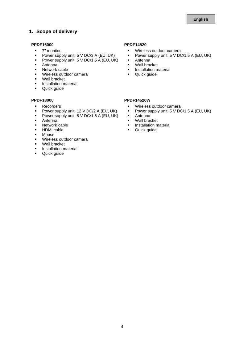
1. Scope of delivery PPDF16000 7" monitor Power supply unit, 5 V DC/3 A (EU, UK) Power supply unit, 5 V DC/1.5 A (EU, UK) Antenna Network cable Wireless outdoor camera Wall bracket Installation material Quick guide
PPDF14520 Wireless outdoor camera Power supply unit, 5 V DC/1.5 A (EU, UK) Antenna Wall bracket Installation material Quick guide
PPDF18000 Recorders Power supply unit, 12 V DC/2 A (EU, UK) Power supply unit, 5 V DC/1.5 A (EU, UK) Antenna Network cable HDMI cable Mouse Wireless outdoor camera Wall bracket Installation material Quick guide
PPDF14520W Wireless outdoor camera Power supply unit, 5 V DC/1.5 A (EU, UK) Antenna Wall bracket Installation material Quick guide
5
English
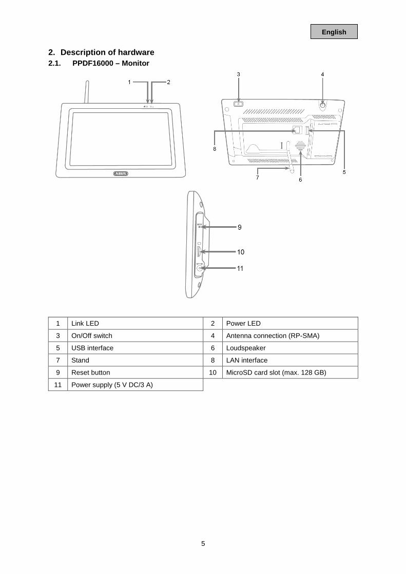
2. Description of hardware 2.1. PPDF16000 – Monitor
1 Link LED 2 Power LED
3 On/Off switch 4 Antenna connection (RP-SMA)
5 USB interface 6 Loudspeaker
7 Stand 8 LAN interface
9 Reset button 10 MicroSD card slot (max. 128 GB)
11 Power supply (5 V DC/3 A)
6
English
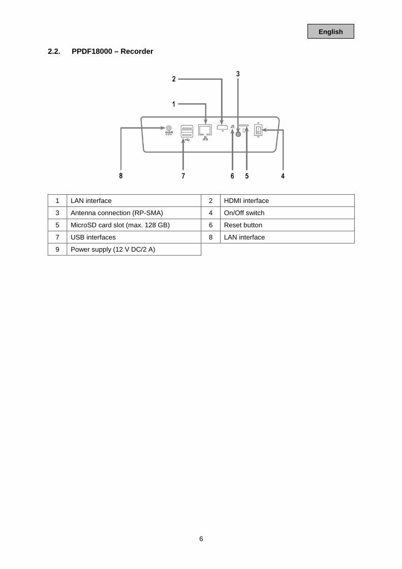
2.2. PPDF18000 – Recorder
1 LAN interface 2 HDMI interface
3 Antenna connection (RP-SMA) 4 On/Off switch
5 MicroSD card slot (max. 128 GB) 6 Reset button
7 USB interfaces 8 LAN interface
9 Power supply (12 V DC/2 A)
7
English
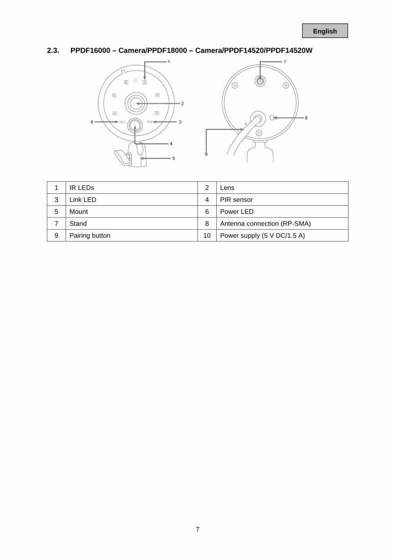
2.3. PPDF16000 – Camera/PPDF18000 – Camera/PPDF14520/PPDF14520W
1 IR LEDs 2 Lens
3 Link LED 4 PIR sensor
5 Mount 6 Power LED
7 Stand 8 Antenna connection (RP-SMA)
9 Pairing button 10 Power supply (5 V DC/1.5 A)
8
English
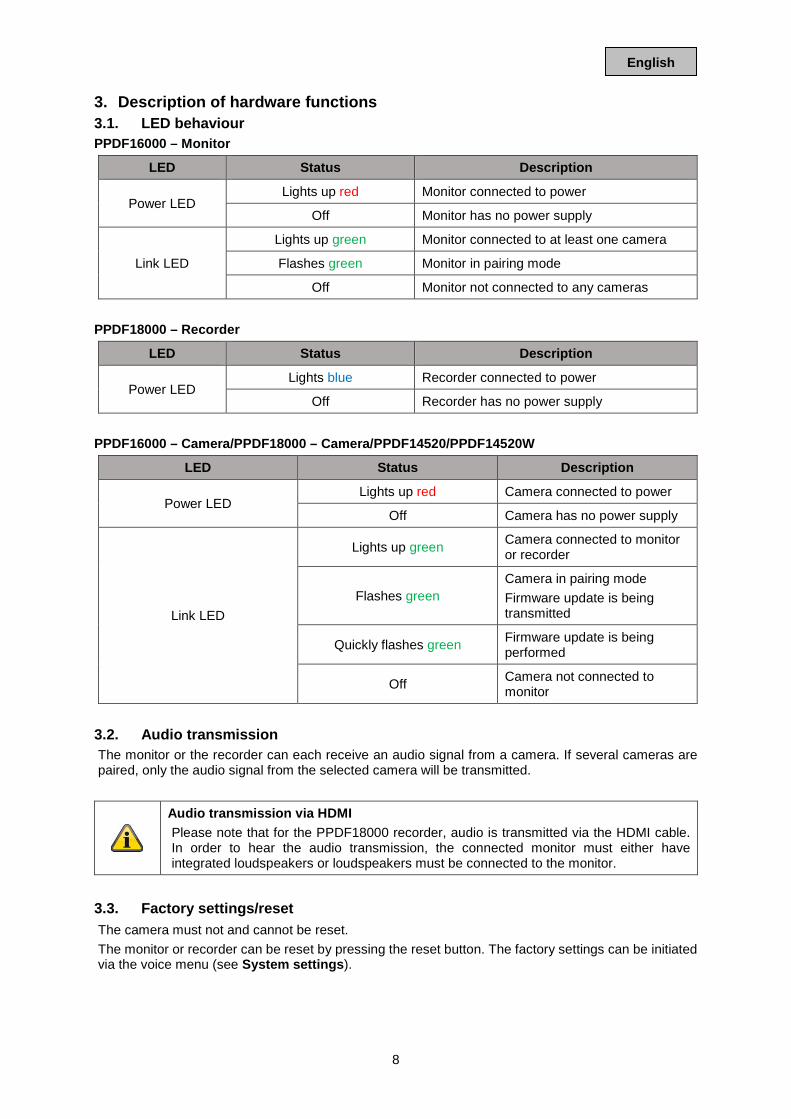
3. Description of hardware functions 3.1. LED behaviour PPDF16000 – Monitor
LED Status Description
Power LED Lights up red Monitor connected to power
Off Monitor has no power supply
Link LED
Lights up green Monitor connected to at least one camera
Flashes green Monitor in pairing mode
Off Monitor not connected to any cameras PPDF18000 – Recorder
LED Status Description
Power LED Lights blue Recorder connected to power
Off Recorder has no power supply PPDF16000 – Camera/PPDF18000 – Camera/PPDF14520/PPDF14520W
LED Status Description
Power LED Lights up red Camera connected to power
Off Camera has no power supply
Link LED
Lights up green Camera connected to monitor or recorder
Flashes green Camera in pairing mode Firmware update is being transmitted
Quickly flashes green Firmware update is being performed
Off Camera not connected to monitor
3.2. Audio transmission The monitor or the recorder can each receive an audio signal from a camera. If several cameras are paired, only the audio signal from the selected camera will be transmitted.
Audio transmission via HDMI Please note that for the PPDF18000 recorder, audio is transmitted via the HDMI cable. In order to hear the audio transmission, the connected monitor must either have integrated loudspeakers or loudspeakers must be connected to the monitor.
3.3. Factory settings/reset The camera must not and cannot be reset. The monitor or recorder can be reset by pressing the reset button. The factory settings can be initiated via the voice menu (see System settings).
9
English
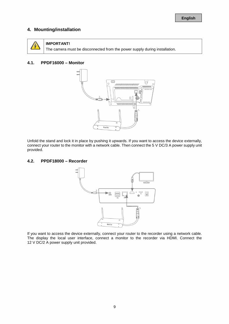
4. Mounting/installation
IMPORTANT! The camera must be disconnected from the power supply during installation.
4.1. PPDF16000 – Monitor
Unfold the stand and lock it in place by pushing it upwards. If you want to access the device externally, connect your router to the monitor with a network cable. Then connect the 5 V DC/3 A power supply unit provided. 4.2. PPDF18000 – Recorder
If you want to access the device externally, connect your router to the recorder using a network cable. The display the local user interface, connect a monitor to the recorder via HDMI. Connect the 12 V DC/2 A power supply unit provided.
10
English
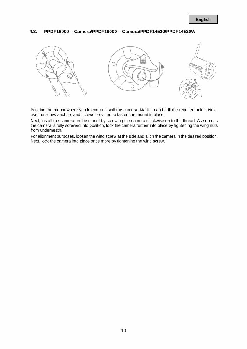
4.3. PPDF16000 – Camera/PPDF18000 – Camera/PPDF14520/PPDF14520W
Position the mount where you intend to install the camera. Mark up and drill the required holes. Next, use the screw anchors and screws provided to fasten the mount in place. Next, install the camera on the mount by screwing the camera clockwise on to the thread. As soon as the camera is fully screwed into position, lock the camera further into place by tightening the wing nuts from underneath. For alignment purposes, loosen the wing screw at the side and align the camera in the desired position. Next, lock the camera into place once more by tightening the wing screw.
11
English
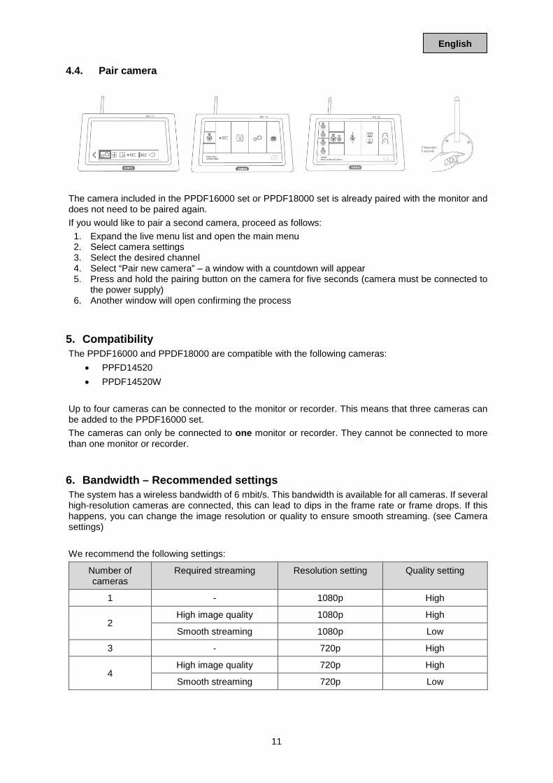
4.4. Pair camera
The camera included in the PPDF16000 set or PPDF18000 set is already paired with the monitor and does not need to be paired again. If you would like to pair a second camera, proceed as follows:
1. Expand the live menu list and open the main menu 2. Select camera settings 3. Select the desired channel 4. Select “Pair new camera” – a window with a countdown will appear 5. Press and hold the pairing button on the camera for five seconds (camera must be connected to
the power supply) 6. Another window will open confirming the process
5. Compatibility The PPDF16000 and PPDF18000 are compatible with the following cameras:
• PPFD14520 • PPDF14520W
Up to four cameras can be connected to the monitor or recorder. This means that three cameras can be added to the PPDF16000 set. The cameras can only be connected to one monitor or recorder. They cannot be connected to more than one monitor or recorder.
6. Bandwidth – Recommended settings The system has a wireless bandwidth of 6 mbit/s. This bandwidth is available for all cameras. If several high-resolution cameras are connected, this can lead to dips in the frame rate or frame drops. If this happens, you can change the image resolution or quality to ensure smooth streaming. (see Camera settings) We recommend the following settings:
Number of cameras
Required streaming Resolution setting Quality setting
1 - 1080p High
2 High image quality 1080p High
Smooth streaming 1080p Low
3 - 720p High
4 High image quality 720p High
Smooth streaming 720p Low
12
English
7. Local user interface 7.1. Operation PPDF16000 The monitor can be operated using touch input.
General operation Please note that when using the touch display, it can take the monitor up to approx. half a second to process inputs.
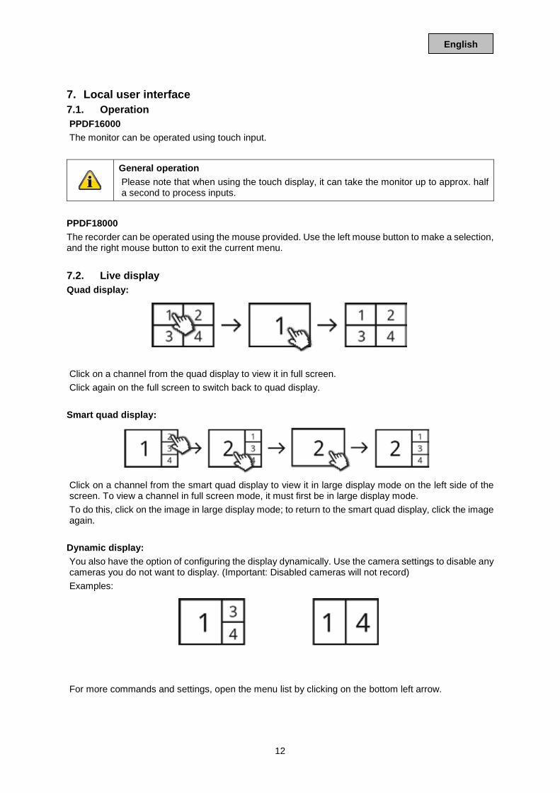
PPDF18000 The recorder can be operated using the mouse provided. Use the left mouse button to make a selection, and the right mouse button to exit the current menu. 7.2. Live display Quad display:
Click on a channel from the quad display to view it in full screen. Click again on the full screen to switch back to quad display.
Smart quad display:
Click on a channel from the smart quad display to view it in large display mode on the left side of the screen. To view a channel in full screen mode, it must first be in large display mode. To do this, click on the image in large display mode; to return to the smart quad display, click the image again.
Dynamic display: You also have the option of configuring the display dynamically. Use the camera settings to disable any cameras you do not want to display. (Important: Disabled cameras will not record) Examples:
For more commands and settings, open the menu list by clicking on the bottom left arrow.
13
English
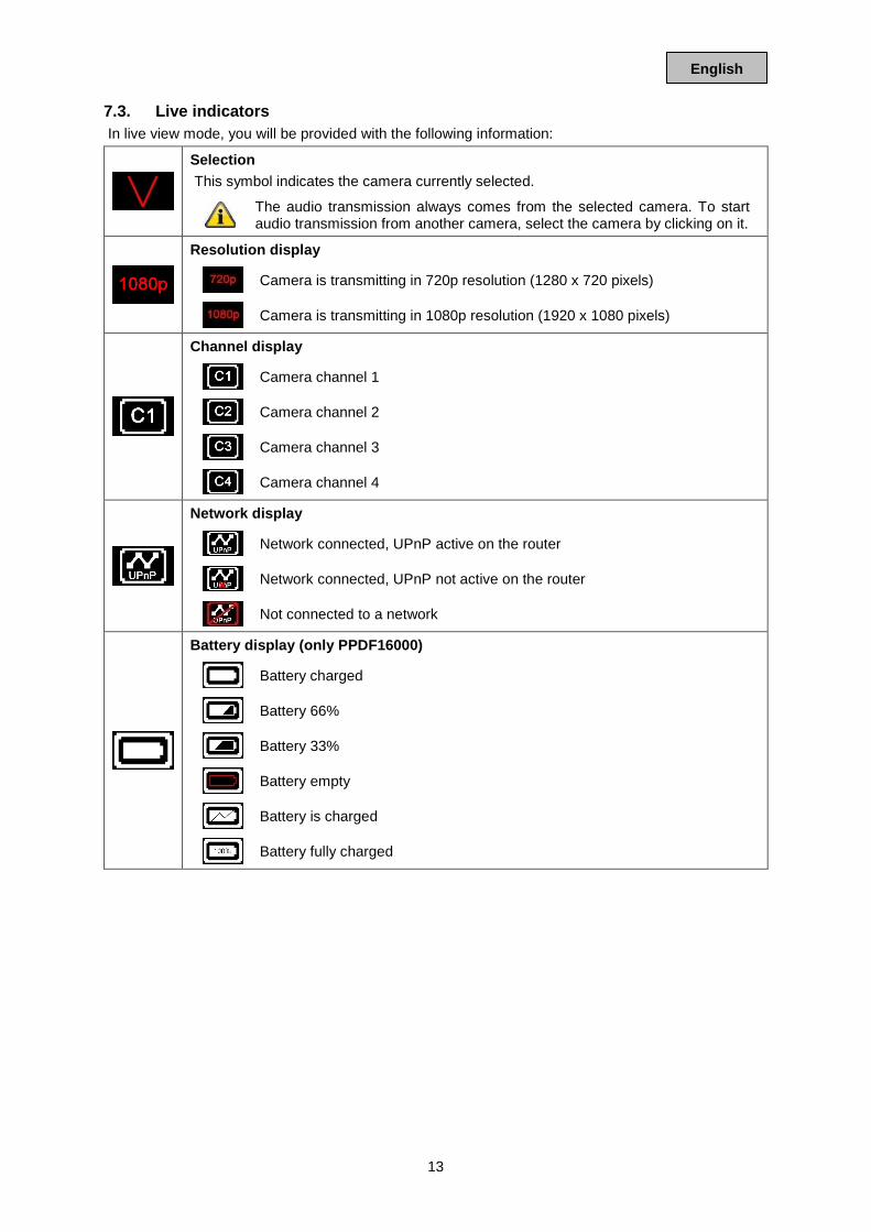
7.3. Live indicators In live view mode, you will be provided with the following information:
Selection This symbol indicates the camera currently selected.
The audio transmission always comes from the selected camera. To start audio transmission from another camera, select the camera by clicking on it.
Resolution display
Camera is transmitting in 720p resolution (1280 x 720 pixels)
Camera is transmitting in 1080p resolution (1920 x 1080 pixels)
Channel display
Camera channel 1
Camera channel 2
Camera channel 3
Camera channel 4
Network display
Network connected, UPnP active on the router
Network connected, UPnP not active on the router
Not connected to a network
Battery display (only PPDF16000)
Battery charged
Battery 66%
Battery 33%
Battery empty
Battery is charged
Battery fully charged
14
English
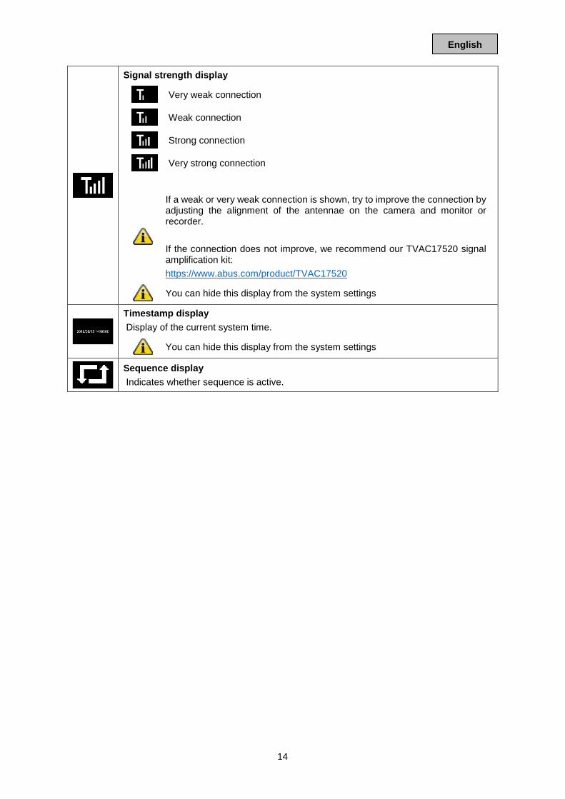
Signal strength display
Very weak connection
Weak connection
Strong connection
Very strong connection
If a weak or very weak connection is shown, try to improve the connection by adjusting the alignment of the antennae on the camera and monitor or recorder. If the connection does not improve, we recommend our TVAC17520 signal amplification kit: https://www.abus.com/product/TVAC17520
You can hide this display from the system settings
Timestamp display Display of the current system time.
You can hide this display from the system settings
Sequence display Indicates whether sequence is active.
15
English
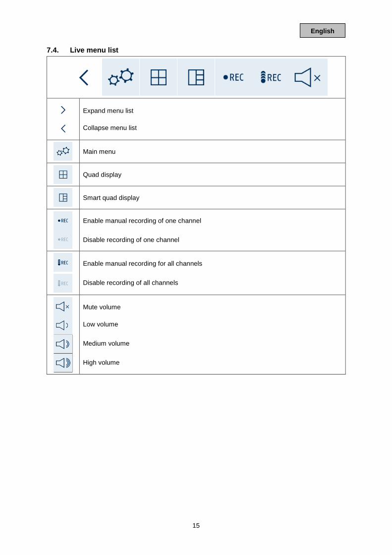
7.4. Live menu list
Expand menu list Collapse menu list
Main menu
Quad display
Smart quad display
Enable manual recording of one channel Disable recording of one channel
Enable manual recording for all channels Disable recording of all channels
Mute volume Low volume Medium volume High volume
16
English
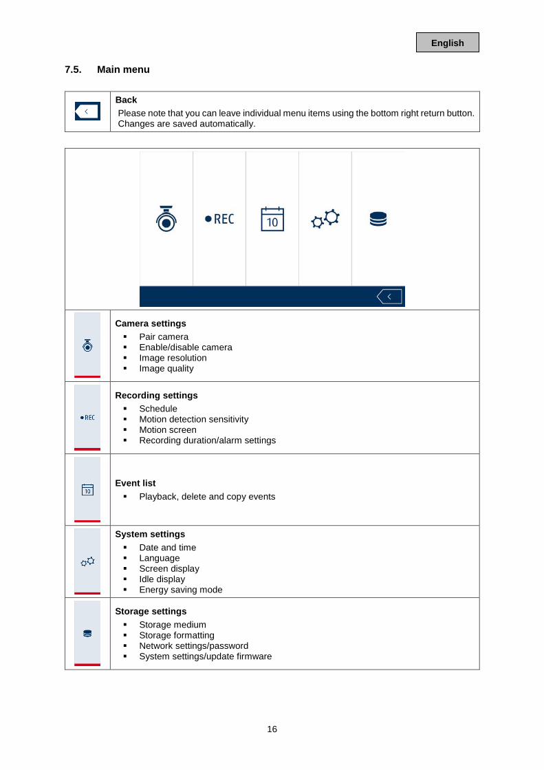
7.5. Main menu
Back Please note that you can leave individual menu items using the bottom right return button. Changes are saved automatically.
Camera settings Pair camera Enable/disable camera Image resolution Image quality
Recording settings Schedule Motion detection sensitivity Motion screen Recording duration/alarm settings
Event list Playback, delete and copy events
System settings Date and time Language Screen display Idle display Energy saving mode
Storage settings Storage medium Storage formatting Network settings/password System settings/update firmware
17
English
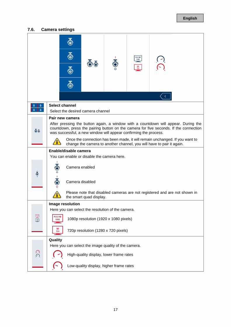
7.6. Camera settings
Select channel Select the desired camera channel
Pair new camera After pressing the button again, a window with a countdown will appear. During the countdown, press the pairing button on the camera for five seconds. If the connection was successful, a new window will appear confirming the process.
Once the connection has been made, it will remain unchanged. If you want to change the camera to another channel, you will have to pair it again.
Enable/disable camera You can enable or disable the camera here.
Camera enabled
Camera disabled
Please note that disabled cameras are not registered and are not shown in the smart quad display.
Image resolution Here you can select the resolution of the camera.
1080p resolution (1920 x 1080 pixels)
720p resolution (1280 x 720 pixels)
Quality Here you can select the image quality of the camera.
High-quality display, lower frame rates
Low-quality display, higher frame rates
18
English
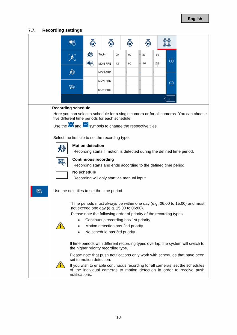
7.7. Recording settings
Recording schedule Here you can select a schedule for a single camera or for all cameras. You can choose five different time periods for each schedule.
Use the and symbols to change the respective tiles. Select the first tile to set the recording type.
Motion detection Recording starts if motion is detected during the defined time period.
Continuous recording Recording starts and ends according to the defined time period.
No schedule Recording will only start via manual input.
Use the next tiles to set the time period.
Time periods must always be within one day (e.g. 06:00 to 15:00) and must not exceed one day (e.g. 15:00 to 06:00). Please note the following order of priority of the recording types:
• Continuous recording has 1st priority • Motion detection has 2nd priority • No schedule has 3rd priority
If time periods with different recording types overlap, the system will switch to the higher priority recording type.
Please note that push notifications only work with schedules that have been set to motion detection. If you wish to enable continuous recording for all cameras, set the schedules of the individual cameras to motion detection in order to receive push notifications.
19
English
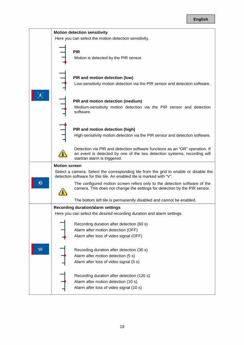
Motion detection sensitivity Here you can select the motion detection sensitivity.
PIR Motion is detected by the PIR sensor.
PIR and motion detection (low) Low-sensitivity motion detection via the PIR sensor and detection software.
PIR and motion detection (medium) Medium-sensitivity motion detection via the PIR sensor and detection software.
PIR and motion detection (high) High-sensitivity motion detection via the PIR sensor and detection software.
Detection via PIR and detection software functions as an “OR” operation. If an event is detected by one of the two detection systems, recording will start/an alarm is triggered.
Motion screen Select a camera. Select the corresponding tile from the grid to enable or disable the detection software for this tile. An enabled tile is marked with “V”.
The configured motion screen refers only to the detection software of the camera. This does not change the settings for detection by the PIR sensor. The bottom left tile is permanently disabled and cannot be enabled.
Recording duration/alarm settings Here you can select the desired recording duration and alarm settings.
Recording duration after detection (60 s) Alarm after motion detection (OFF) Alarm after loss of video signal (OFF)
Recording duration after detection (30 s) Alarm after motion detection (5 s) Alarm after loss of video signal (5 s)
Recording duration after detection (120 s) Alarm after motion detection (10 s) Alarm after loss of video signal (10 s)
20
English
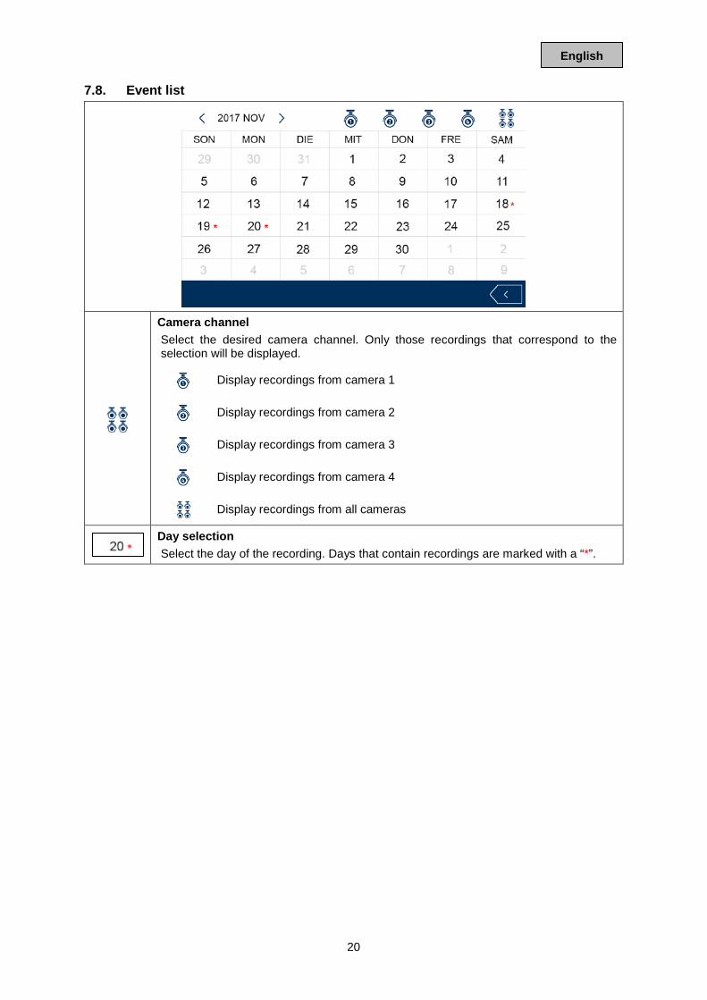
7.8. Event list
Camera channel Select the desired camera channel. Only those recordings that correspond to the selection will be displayed.
Display recordings from camera 1
Display recordings from camera 2
Display recordings from camera 3
Display recordings from camera 4
Display recordings from all cameras
Day selection Select the day of the recording. Days that contain recordings are marked with a “*”.
21
English
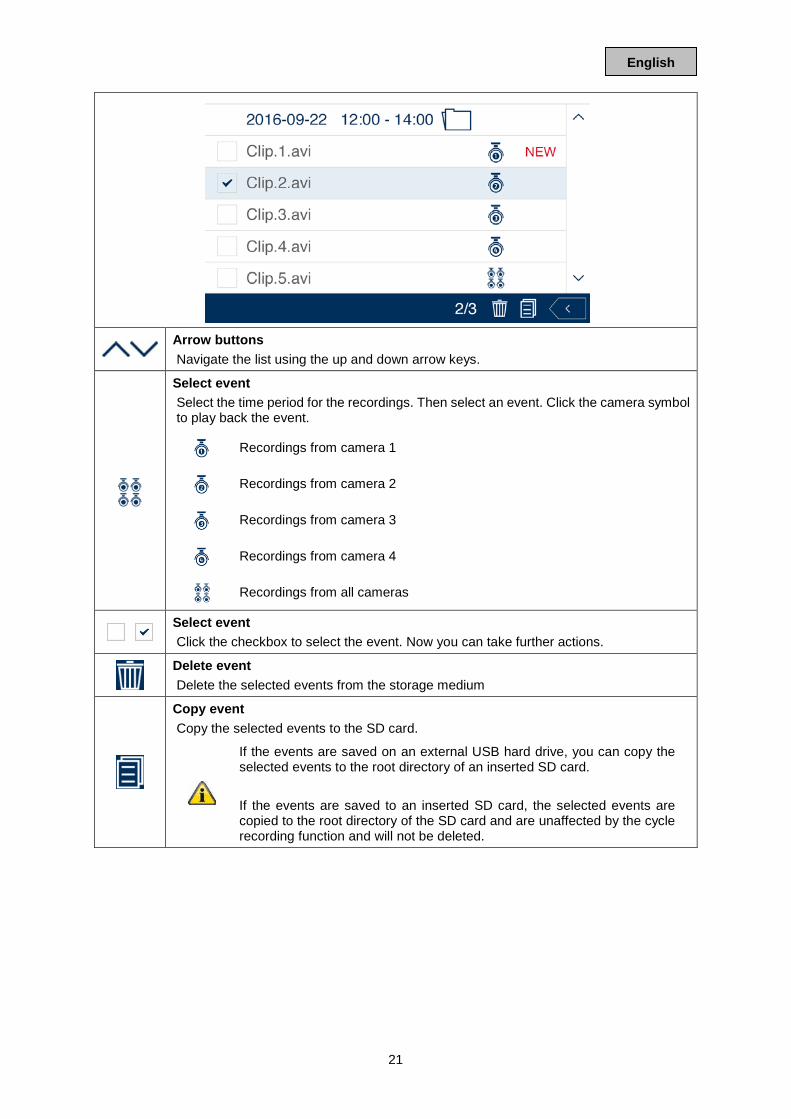
Arrow buttons Navigate the list using the up and down arrow keys.
Select event Select the time period for the recordings. Then select an event. Click the camera symbol to play back the event.
Recordings from camera 1
Recordings from camera 2
Recordings from camera 3
Recordings from camera 4
Recordings from all cameras
Select event Click the checkbox to select the event. Now you can take further actions.
Delete event Delete the selected events from the storage medium
Copy event Copy the selected events to the SD card.
If the events are saved on an external USB hard drive, you can copy the selected events to the root directory of an inserted SD card. If the events are saved to an inserted SD card, the selected events are copied to the root directory of the SD card and are unaffected by the cycle recording function and will not be deleted.
22
English
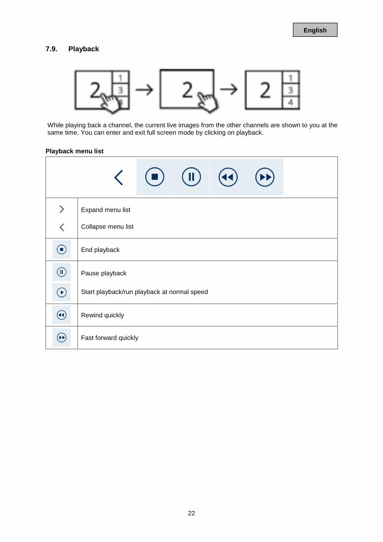
7.9. Playback
While playing back a channel, the current live images from the other channels are shown to you at the same time. You can enter and exit full screen mode by clicking on playback.
Playback menu list
Expand menu list Collapse menu list
End playback
Pause playback Start playback/run playback at normal speed
Rewind quickly
Fast forward quickly
23
English
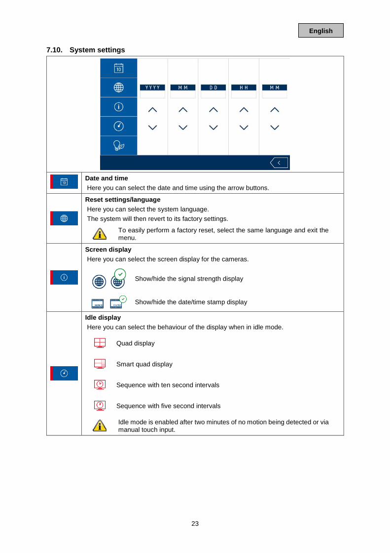
7.10. System settings
Date and time Here you can select the date and time using the arrow buttons.
Reset settings/language Here you can select the system language. The system will then revert to its factory settings.
To easily perform a factory reset, select the same language and exit the menu.
Screen display Here you can select the screen display for the cameras.
Show/hide the signal strength display
Show/hide the date/time stamp display
Idle display Here you can select the behaviour of the display when in idle mode.
Quad display
Smart quad display
Sequence with ten second intervals
Sequence with five second intervals
Idle mode is enabled after two minutes of no motion being detected or via manual touch input.
24
English
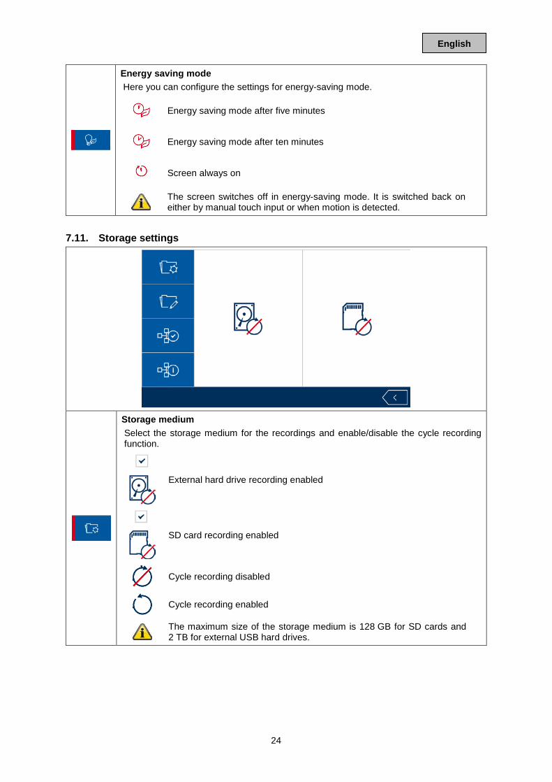
Energy saving mode Here you can configure the settings for energy-saving mode.
Energy saving mode after five minutes
Energy saving mode after ten minutes
Screen always on
The screen switches off in energy-saving mode. It is switched back on either by manual touch input or when motion is detected.
7.11. Storage settings
Storage medium Select the storage medium for the recordings and enable/disable the cycle recording function.
External hard drive recording enabled
SD card recording enabled
Cycle recording disabled
Cycle recording enabled
The maximum size of the storage medium is 128 GB for SD cards and 2 TB for external USB hard drives.
25
English
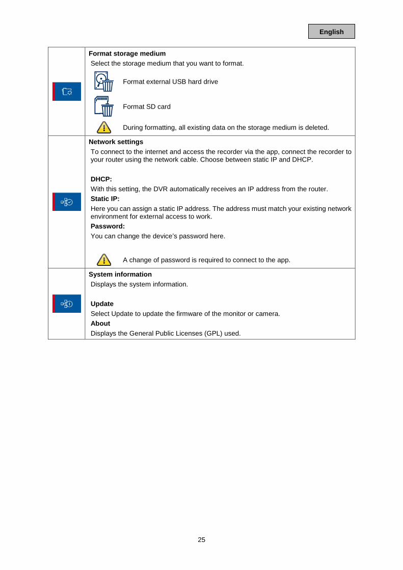
Format storage medium Select the storage medium that you want to format.
Format external USB hard drive
Format SD card
During formatting, all existing data on the storage medium is deleted.
Network settings To connect to the internet and access the recorder via the app, connect the recorder to your router using the network cable. Choose between static IP and DHCP. DHCP: With this setting, the DVR automatically receives an IP address from the router. Static IP: Here you can assign a static IP address. The address must match your existing network environment for external access to work. Password: You can change the device’s password here.
A change of password is required to connect to the app.
System information Displays the system information. Update Select Update to update the firmware of the monitor or camera. About Displays the General Public Licenses (GPL) used.
26
English
8. ABUS OneLook – External operation 8.1. General information By default, the system will select the widely-used UPnP (Universal Plug and Play) solution. If your router supports this function, you should enable it in order to improve connection quality. If your router does not support this function, the system will select another connection method by default. This can have a negative effect on connection quality. Make sure to check whether your router supports the UPnP function and enable it if it does. 8.2. Download app Download the “ABUS OneLook” app from the Google Play Store or Apple App Store before accessing for the first time. 8.3. Differences between Android/iOS versions The screenshots in the following points were taken from the iOS app. In terms of functionality, the Android and iOS versions of the app are identical but differ slightly in terms of their operation.
Live view menu In the iOS version, the live view menu is displayed in a bar with icons. In the Android version, the live view menu can be expanded from the top right or opened by pressing the “Menu button” on your Android smartphone/tablet. In Android, the menu is marked with text here.
Back In the iOS version, you can exit menus by pressing the back button on the screen. In the Android version you can achieve this by pressing the dedicated back button on your Android smartphone/tablet.
27
English
8.4. Device list
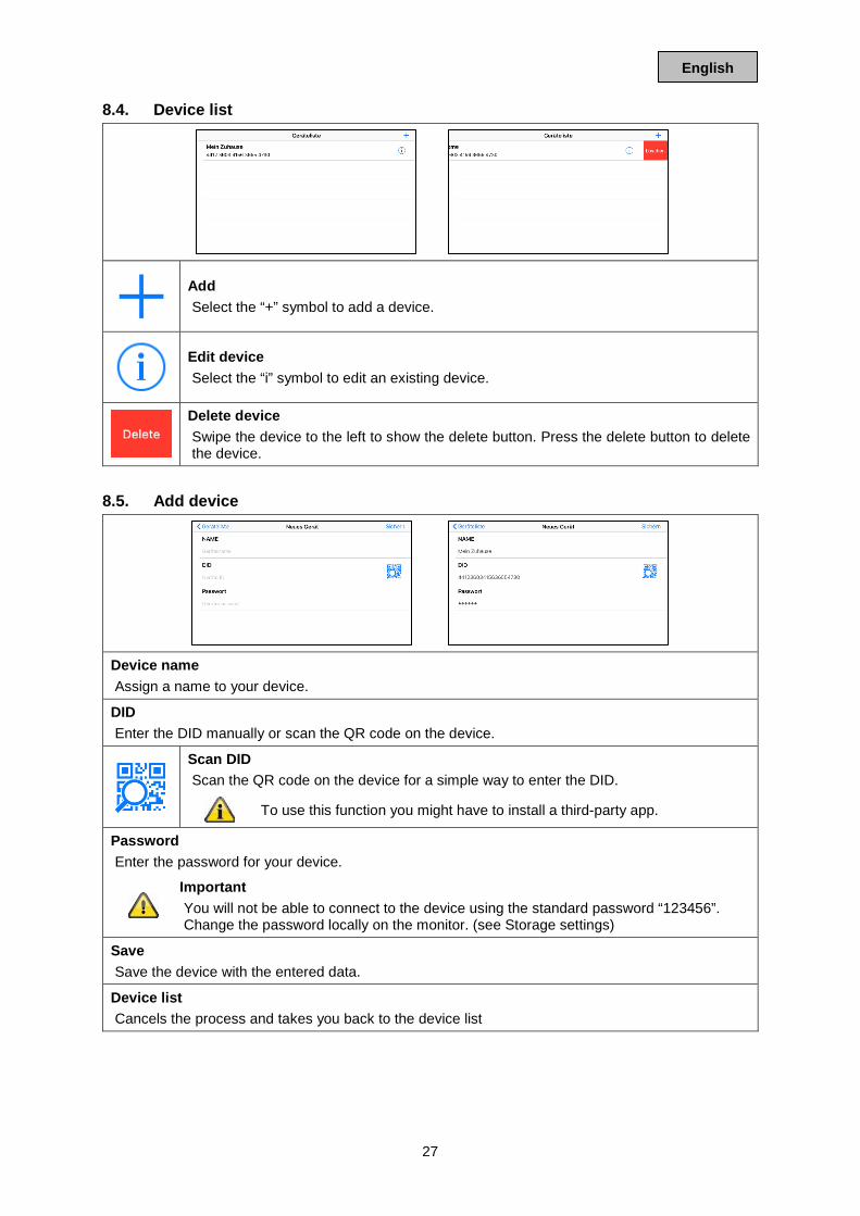
Add Select the “+” symbol to add a device.
Edit device Select the “i” symbol to edit an existing device.
Delete device Swipe the device to the left to show the delete button. Press the delete button to delete the device.
8.5. Add device
Device name Assign a name to your device.
DID Enter the DID manually or scan the QR code on the device.
Scan DID Scan the QR code on the device for a simple way to enter the DID.
To use this function you might have to install a third-party app.
Password Enter the password for your device.
Important You will not be able to connect to the device using the standard password “123456”. Change the password locally on the monitor. (see Storage settings)
Save Save the device with the entered data.
Device list Cancels the process and takes you back to the device list
28
English
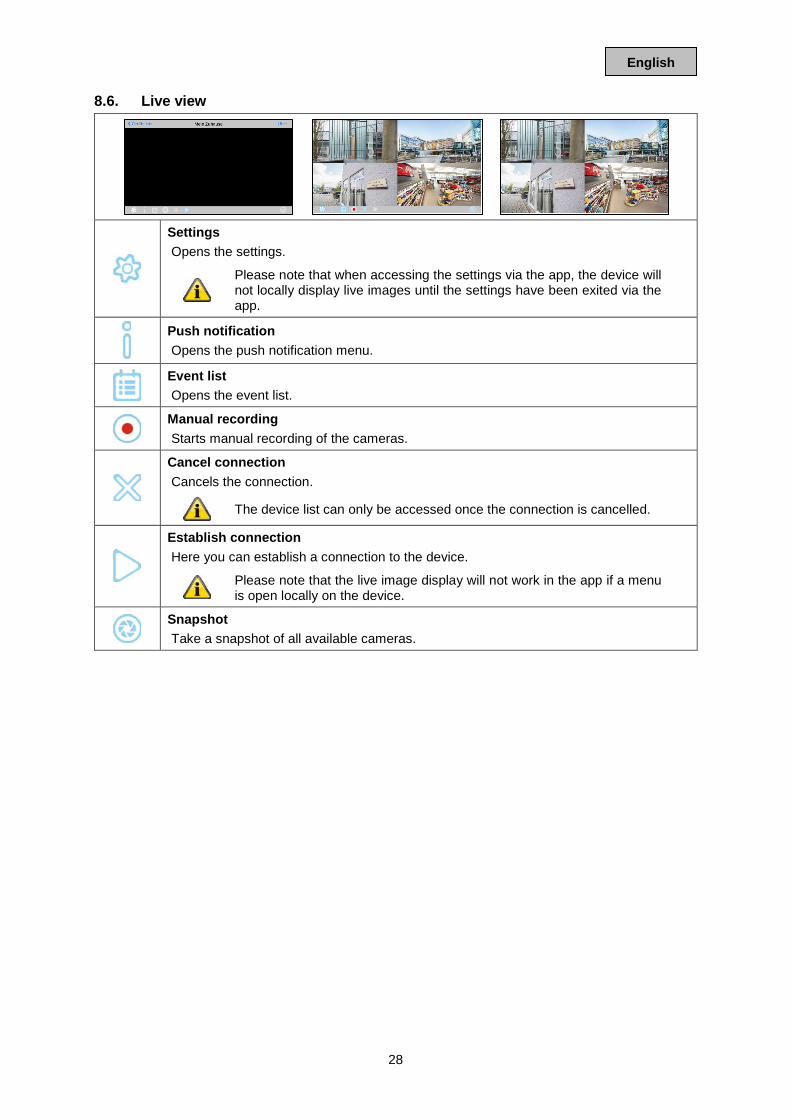
8.6. Live view
Settings Opens the settings.
Please note that when accessing the settings via the app, the device will not locally display live images until the settings have been exited via the app.
Push notification Opens the push notification menu.
Event list Opens the event list.
Manual recording Starts manual recording of the cameras.
Cancel connection Cancels the connection.
The device list can only be accessed once the connection is cancelled.
Establish connection Here you can establish a connection to the device.
Please note that the live image display will not work in the app if a menu is open locally on the device.
Snapshot Take a snapshot of all available cameras.
29
English
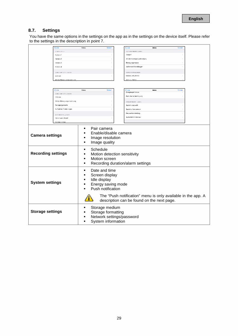
8.7. Settings You have the same options in the settings on the app as in the settings on the device itself. Please refer to the settings in the description in point 7.
Camera settings Pair camera Enable/disable camera Image resolution Image quality
Recording settings
Schedule Motion detection sensitivity Motion screen Recording duration/alarm settings
System settings
Date and time Screen display Idle display Energy saving mode Push notification
The “Push notification” menu is only available in the app. A description can be found on the next page.
Storage settings
Storage medium Storage formatting Network settings/password System information
30
English
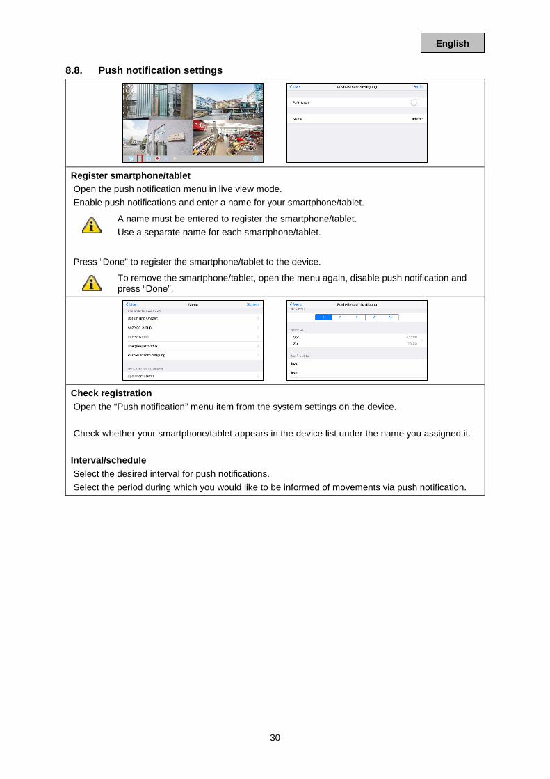
8.8. Push notification settings
Register smartphone/tablet Open the push notification menu in live view mode. Enable push notifications and enter a name for your smartphone/tablet.
A name must be entered to register the smartphone/tablet. Use a separate name for each smartphone/tablet.
Press “Done” to register the smartphone/tablet to the device.
To remove the smartphone/tablet, open the menu again, disable push notification and press “Done”.
Check registration Open the “Push notification” menu item from the system settings on the device. Check whether your smartphone/tablet appears in the device list under the name you assigned it.
Interval/schedule Select the desired interval for push notifications. Select the period during which you would like to be informed of movements via push notification.