Embed Size (px)
Citation preview
WinSystems, Inc.715 Stadium DriveArlington, TX 76011
http://www.winsystems.com
WinSystems ®
PPC3-1212.1” AM TFT Panel with Touchscreen
PRODUCT MANUAL
140226 PRODUCT MANUAL PPC3-12 2
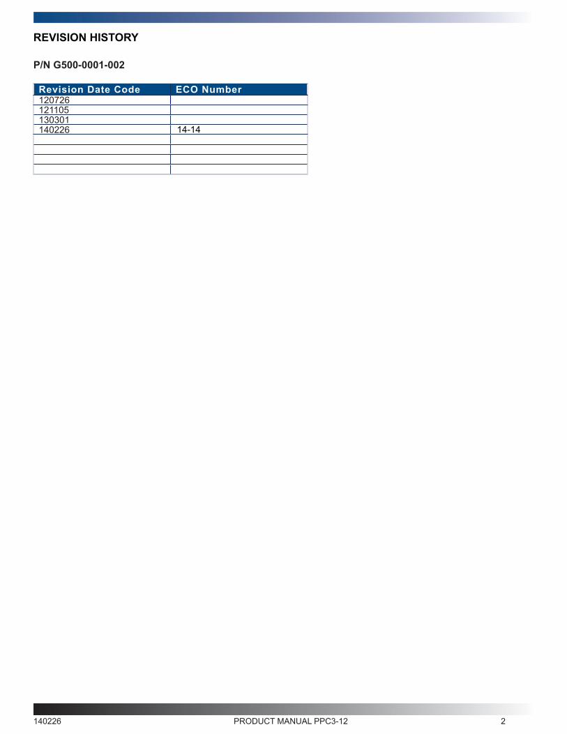
P/N G500-0001-002
Revision Date Code ECO Number120726121105130301140226
REVISION HISTORY
14-14
140226 PRODUCT MANUAL PPC3-12 3
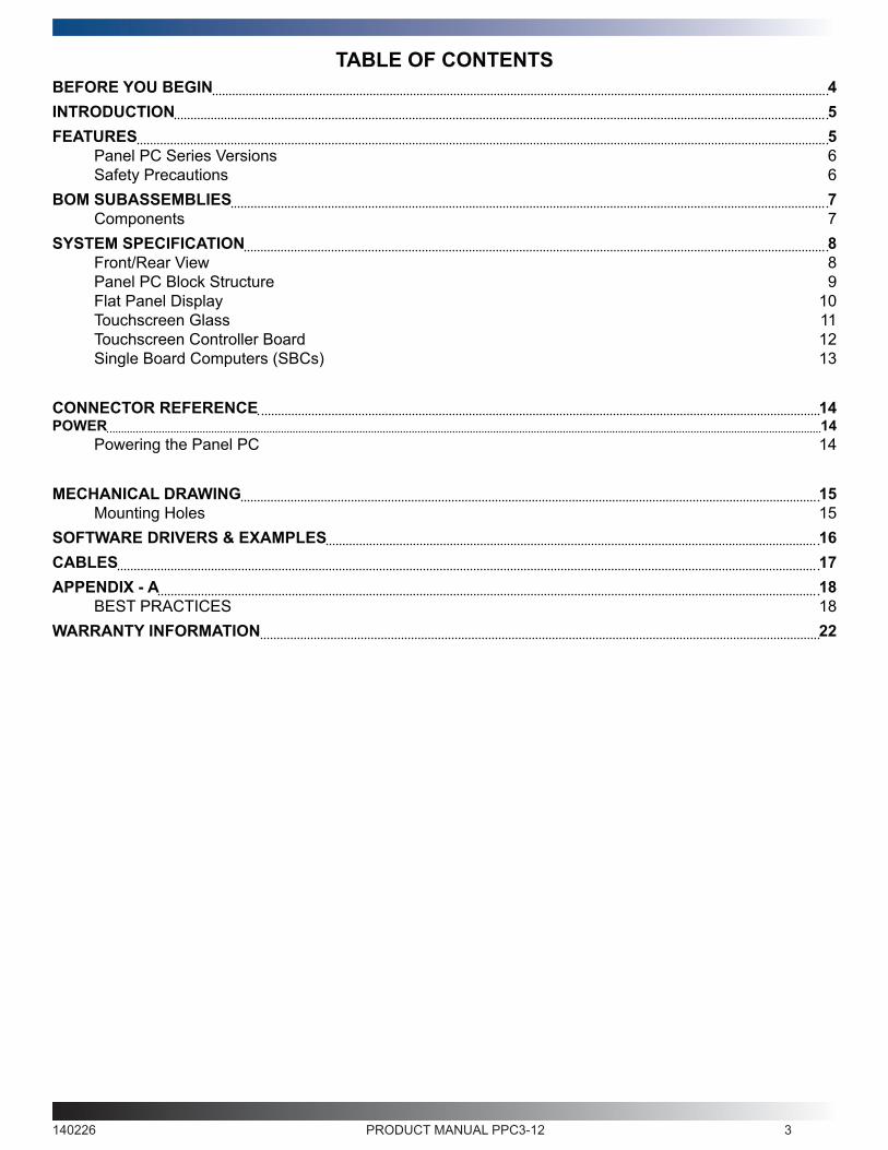
TABLE OF CONTENTSBEFORE YOU BEGIN 4INTRODUCTION 5FEATURES 5
Panel PC Series Versions 6Safety Precautions 6
BOM SUBASSEMBLIES 7Components 7
SYSTEM SPECIFICATION 8Front/Rear View 8Panel PC Block Structure 9Flat Panel Display 10Touchscreen Glass 11Touchscreen Controller Board 12Single Board Computers (SBCs) 13
CONNECTOR REFERENCE 14POWER 14
Powering the Panel PC 14
MECHANICAL DRAWING 15Mounting Holes 15
SOFTWARE DRIVERS & EXAMPLES 16CABLES 17APPENDIX - A 18
BEST PRACTICES 18WARRANTY INFORMATION 22
140226 PRODUCT MANUAL PPC3-12 4
BEFORE YOU BEGINWinSystems offers best practice recommendations for using and handling WinSystems products. These methods include
valuable advice to provide an optimal user experience and to prevent damage to yourself and/or the product.
YOU MAY VOID YOUR WARRANTY AND/OR DAMAGE THE PRODUCT BY FAILING TO COMPLY WITH THESE BEST
PRACTICES.
Reference Appendix - A for Best Practices.
For any questions you may have on WinSystems products, contact our Technical Support Group at (817) 274-7553, Monday
through Friday, between 8 AM and 5 PM Central Standard Time (CST).
Please review these guidelines carefully and follow them to ensure you are successfully using your product.
This product ships with a heat sink. Product warranty is void if the heat sink is removed from the product.
140226 PRODUCT MANUAL PPC3-12 5
INTRODUCTIONThis manual is intended to provide the necessary information regarding configuration and usage of the PPC3-12 12.1”
Touchscreen Panel PC. WinSystems maintains a Technical Support Group to help answer questions not adequately
addressed in this manual. Contact Technical Support at (817) 274-7553, Monday through Friday, between 8 AM and 5
PM Central Standard Time (CST).
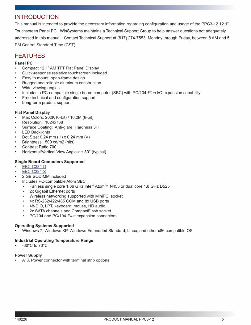
FEATURESPanel PC• Compact 12.1” AM TFT Flat Panel Display• Quick-response resistive touchscreen included• Easy to mount, open-frame design• Rugged and reliable aluminum construction• Wide viewing angles• Includes a PC-compatible single board computer (SBC) with PC/104-Plus I/O expansion capability• Free technical and configuration support• Long-term product support Flat Panel Display• Max Colors: 262K (6-bit) / 16.2M (8-bit) • Resolution: 1024x768• Surface Coating: Anti-glare, Hardness 3H• LED Backlights• Dot Size: 0.24 mm (H) x 0.24 mm (V)• Brightness: 500 cd/m2 (nits)• Contrast Ratio 700:1• Horizontal/Vertical View Angles: ± 80° (typical)
Single Board Computers Supported• EBC-C384-D• EBC-C384-S• 2 GB SODIMM included• Includes PC-compatible Atom SBC
• Fanless single core 1.66 GHz Intel® Atom™ N455 or dual core 1.8 GHz D525• 2x Gigabit Ethernet ports• Wireless networking supported with MiniPCI socket• 4x RS-232/422/485 COM and 8x USB ports• 48-DIO, LPT, keyboard, mouse, HD audio• 2x SATA channels and CompactFlash socket• PC/104 and PC/104-Plus expansion connectors
Operating Systems Supported• Windows 7, Windows XP, Windows Embedded Standard, Linux, and other x86 compatible OS
Industrial Operating Temperature Range• -30°C to 70°C
Power Supply• ATX Power connector with terminal strip options
140226 PRODUCT MANUAL PPC3-12 6
Panel PC Series VersionsThere are four models of the Panel PC available in the PPC3-12 product family. All versions are CompactFlash-ready.
The various models are shown below.
• PPC3-12-0-384-D2 (12.1” Panel PC with dual core 1.8 GHz D525 processor)
• PPC3-12-1-384-D2 (12.1” Panel PC with dual core 1.8 GHz D525 processor and hard disk)
• PPC3-12-0-384-S2 (12.1” Panel PC with single core 1.6 GHz N455 processor)
• PPC3-12-1-384-S2 (12.1” Panel PC with single core 1.6 GHz N455 processor and hard disk)
Safety PrecautionsPlease use the following safety precautions when handling the PPC3-12 Series Panel PC.
This product is static sensitive. Use care when handling to avoid electrostatic discharge.
Caution
Note: WinSystems offers Accessory kits, which include Memory, CompactFlash and CableSets, available to be
purchased separately.
Refer to the invoice detail that shipped with this product for specific information on your shipment.
If any items are damaged or missing from your shipment, contact your WinSystems sales representative.
140226 PRODUCT MANUAL PPC3-12 7
BOM SUBASSEMBLIESComponentsFollowing is a list of components that comprise the PPC3-12-Panel PC Series. Certain part numbers listed below are
applicable depending on the Panel PC series model purchased.
Part Number DescriptionEBC-C384-D (EBX Dual-core Single Board Computer)
EBC-C384-S (EBX Single-core Single Board Computer)
SODIMM204-3-85-2G (2 GB DDR3 RAM Memory)
G550-0001-003 (SATA Hard Drive) *for applicable versions
ADP-IO-USB-002 (USB Adapter Board)
BAT-LTC-E-36-16-1 (3.6V 1650 Battery)
140226 PRODUCT MANUAL PPC3-12 8
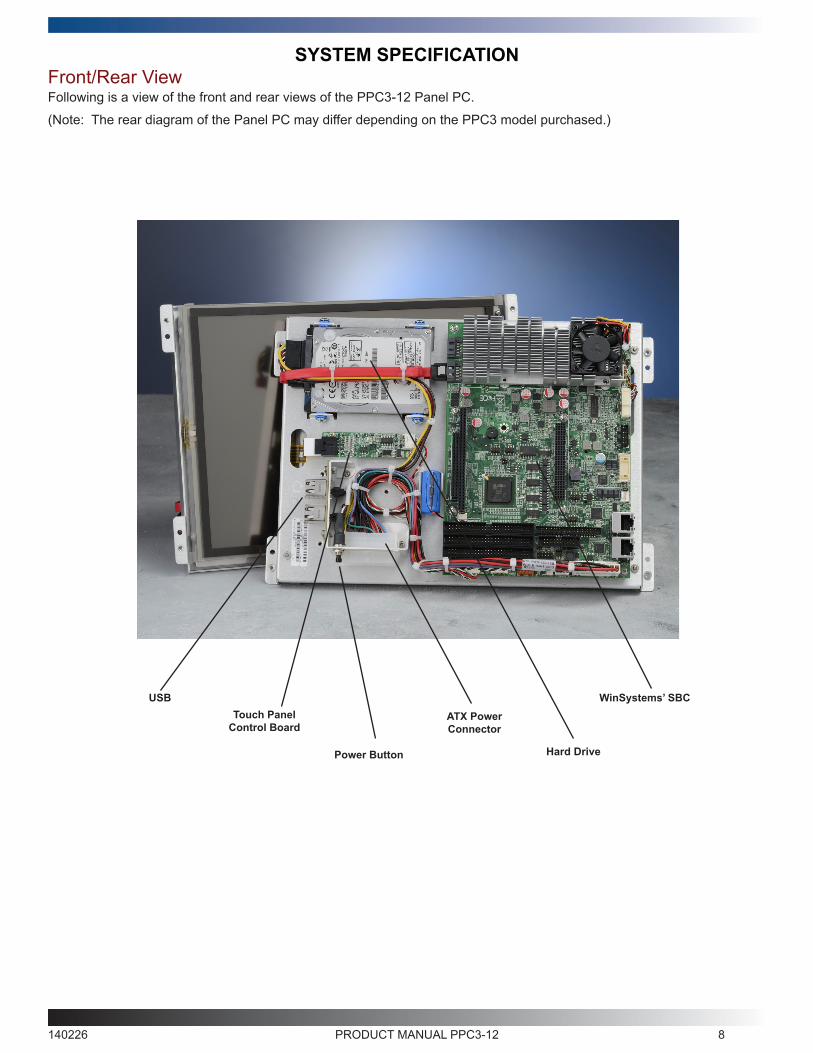
SYSTEM SPECIFICATIONFront/Rear ViewFollowing is a view of the front and rear views of the PPC3-12 Panel PC.
(Note: The rear diagram of the Panel PC may differ depending on the PPC3 model purchased.)
WinSystems’ SBCTouch Panel
Control Board
Hard DrivePower Button
ATX Power Connector
USB
140226 PRODUCT MANUAL PPC3-12 9
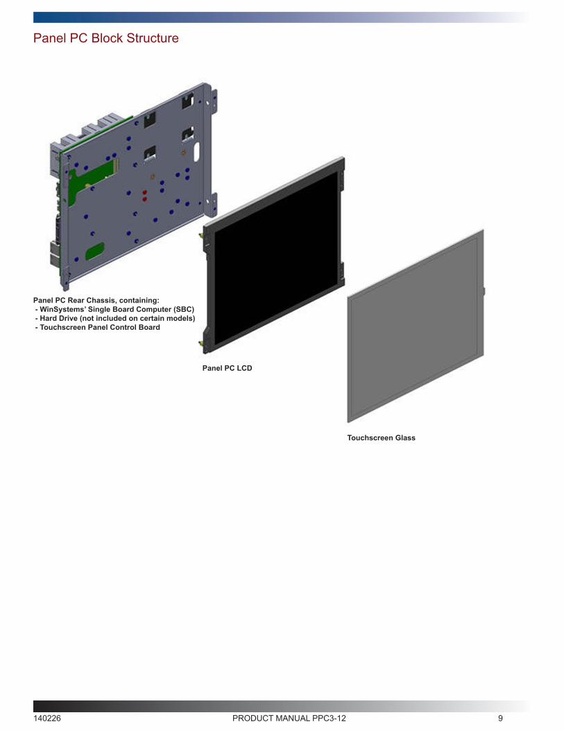
Panel PC Block Structure
Touchscreen Glass
Panel PC LCD
Panel PC Rear Chassis, containing: - WinSystems’ Single Board Computer (SBC) - Hard Drive (not included on certain models) - Touchscreen Panel Control Board
140226 PRODUCT MANUAL PPC3-12 10
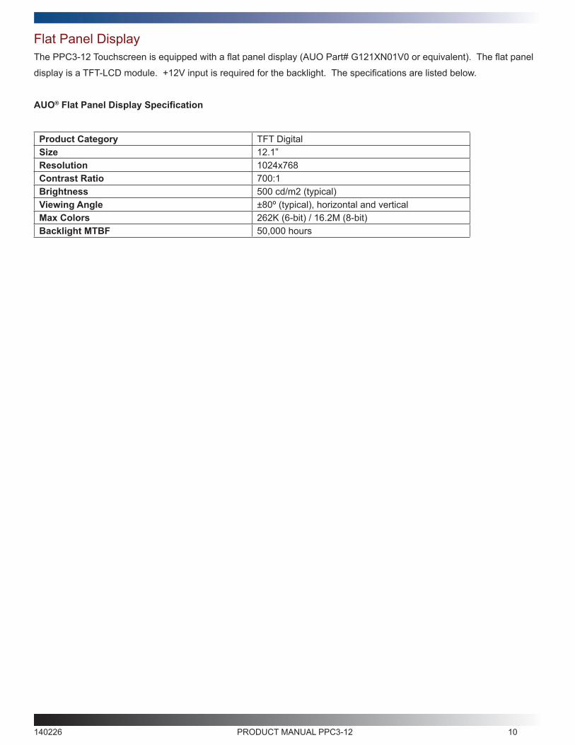
Flat Panel DisplayThe PPC3-12 Touchscreen is equipped with a flat panel display (AUO Part# G121XN01V0 or equivalent). The flat panel
display is a TFT-LCD module. +12V input is required for the backlight. The specifications are listed below.
AUO® Flat Panel Display Specification
Product Category TFT DigitalSize 12.1”Resolution 1024x768Contrast Ratio 700:1Brightness 500 cd/m2 (typical)Viewing Angle ±80º (typical), horizontal and verticalMax Colors 262K (6-bit) / 16.2M (8-bit)Backlight MTBF 50,000 hours
140226 PRODUCT MANUAL PPC3-12 11
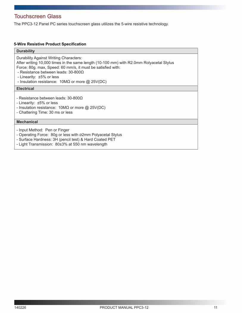
Durability
Durability Against Writing Characters:After writing 10,000 times in the same length (10-100 mm) with R2.0mm Rolyacetal Stylus Force: 80g. max, Speed: 60 mm/s, it must be satisfied with: - Resistance between leads: 30-800Ω - Linearity: ±5% or less - Insulation resistance: 10MΩ or more @ 25V(DC)
Electrical
- Resistance between leads: 30-800Ω- Linearity: ±5% or less - Insulation resistance: 10MΩ or more @ 25V(DC) - Chattering Time: 30 ms or less
Mechanical
- Input Method: Pen or Finger- Operating Force: 80g or less with Ø2mm Polyacetal Stylus - Surface Hardness: 3H (pencil test) & Hard Coated PET- Light Transmission: 80±3% at 550 nm wavelength
Touchscreen GlassThe PPC3-12 Panel PC series touchscreen glass utilizes the 5-wire resistive technology.
5-Wire Resistive Product Specification
140226 PRODUCT MANUAL PPC3-12 12
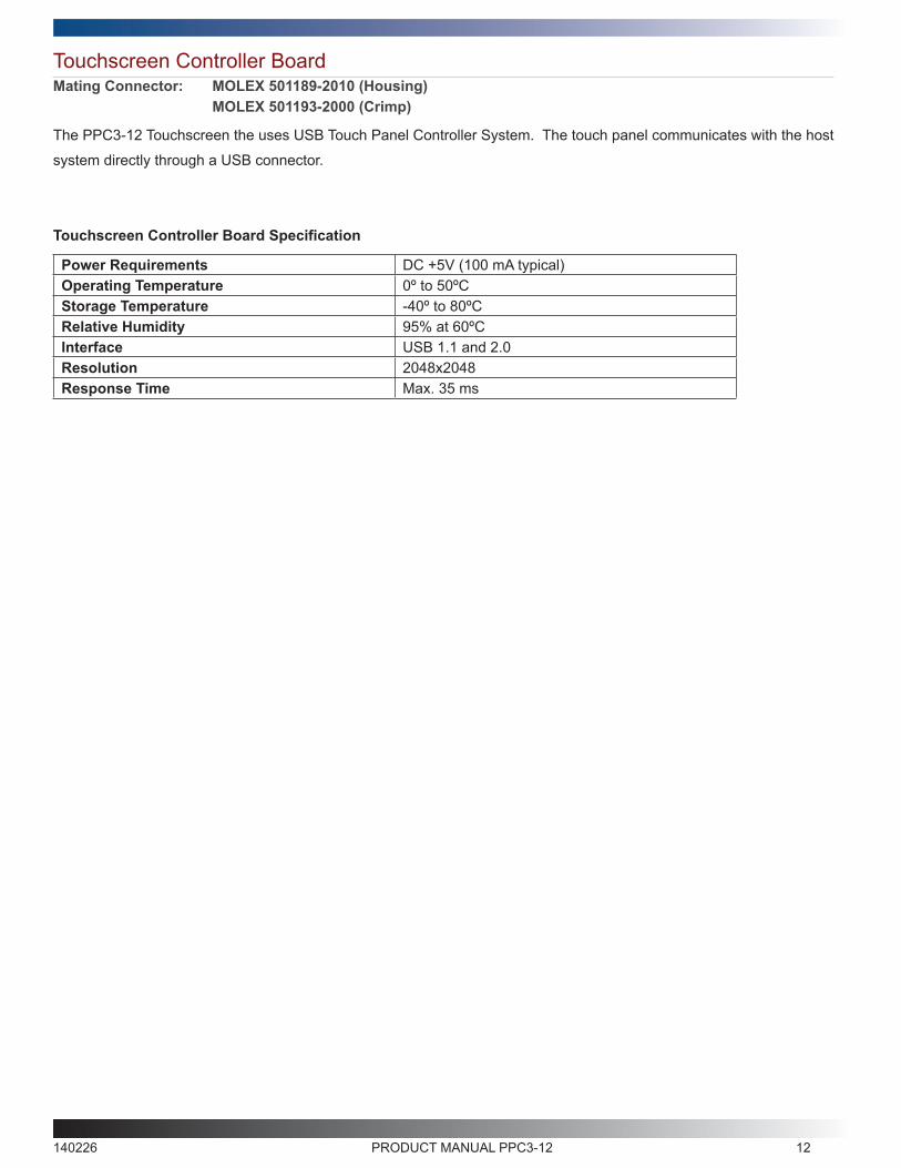
Touchscreen Controller Board
The PPC3-12 Touchscreen the uses USB Touch Panel Controller System. The touch panel communicates with the host
system directly through a USB connector.
Touchscreen Controller Board Specification
Power Requirements DC +5V (100 mA typical)Operating Temperature 0º to 50ºCStorage Temperature -40º to 80ºCRelative Humidity 95% at 60ºCInterface USB 1.1 and 2.0Resolution 2048x2048Response Time Max. 35 ms
Mating Connector: MOLEX 501189-2010 (Housing) MOLEX 501193-2000 (Crimp)
140226 PRODUCT MANUAL PPC3-12 13
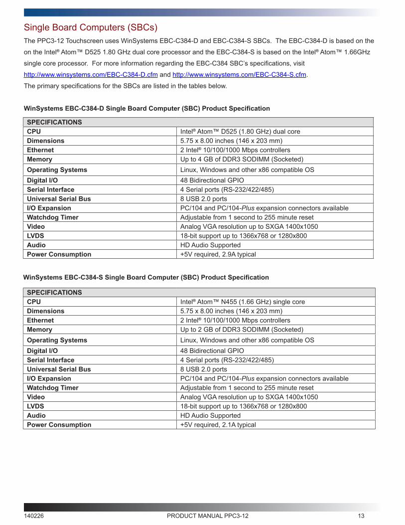
Single Board Computers (SBCs)The PPC3-12 Touchscreen uses WinSystems EBC-C384-D and EBC-C384-S SBCs. The EBC-C384-D is based on the
on the Intel® Atom™ D525 1.80 GHz dual core processor and the EBC-C384-S is based on the Intel® Atom™ 1.66GHz
single core processor. For more information regarding the EBC-C384 SBC’s specifications, visit
http://www.winsystems.com/EBC-C384-D.cfm and http://www.winsystems.com/EBC-C384-S.cfm.
The primary specifications for the SBCs are listed in the tables below.
WinSystems EBC-C384-D Single Board Computer (SBC) Product Specification
SPECIFICATIONSCPU Intel® Atom™ D525 (1.80 GHz) dual coreDimensions 5.75 x 8.00 inches (146 x 203 mm)Ethernet 2 Intel® 10/100/1000 Mbps controllersMemory Up to 4 GB of DDR3 SODIMM (Socketed)Operating Systems Linux, Windows and other x86 compatible OSDigital I/O 48 Bidirectional GPIOSerial Interface 4 Serial ports (RS-232/422/485)Universal Serial Bus 8 USB 2.0 portsI/O Expansion PC/104 and PC/104-Plus expansion connectors availableWatchdog Timer Adjustable from 1 second to 255 minute resetVideo Analog VGA resolution up to SXGA 1400x1050LVDS 18-bit support up to 1366x768 or 1280x800Audio HD Audio SupportedPower Consumption +5V required, 2.9A typical
WinSystems EBC-C384-S Single Board Computer (SBC) Product Specification
SPECIFICATIONSCPU Intel® Atom™ N455 (1.66 GHz) single coreDimensions 5.75 x 8.00 inches (146 x 203 mm)Ethernet 2 Intel® 10/100/1000 Mbps controllersMemory Up to 2 GB of DDR3 SODIMM (Socketed)Operating Systems Linux, Windows and other x86 compatible OSDigital I/O 48 Bidirectional GPIOSerial Interface 4 Serial ports (RS-232/422/485)Universal Serial Bus 8 USB 2.0 portsI/O Expansion PC/104 and PC/104-Plus expansion connectors availableWatchdog Timer Adjustable from 1 second to 255 minute resetVideo Analog VGA resolution up to SXGA 1400x1050LVDS 18-bit support up to 1366x768 or 1280x800Audio HD Audio SupportedPower Consumption +5V required, 2.1A typical
140226 PRODUCT MANUAL PPC3-12 14
CONNECTOR REFERENCE
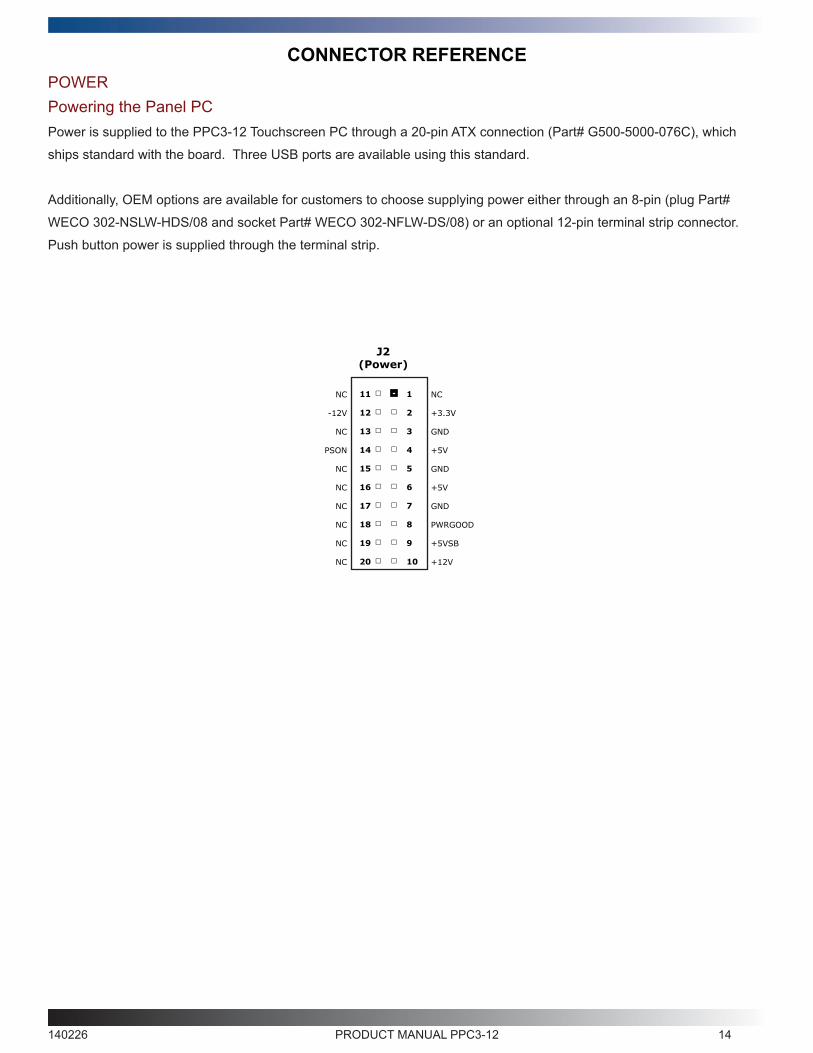
Powering the Panel PCPOWER
Power is supplied to the PPC3-12 Touchscreen PC through a 20-pin ATX connection (Part# G500-5000-076C), which
ships standard with the board. Three USB ports are available using this standard.
Additionally, OEM options are available for customers to choose supplying power either through an 8-pin (plug Part#
WECO 302-NSLW-HDS/08 and socket Part# WECO 302-NFLW-DS/08) or an optional 12-pin terminal strip connector.
Push button power is supplied through the terminal strip.
J2(Power)
11
12
13
14
15
16
17
18
19
20
1
2
3
4
5
6
7
8
9
10
NC
-12V
NC
PSON
NC
NC
NC
NC
NC
NC
NC
+3.3V
GND
+5V
GND
+5V
GND
PWRGOOD
+5VSB
+12V
140226 PRODUCT MANUAL PPC3-12 15
MECHANICAL DRAWING
MO
UN
TIN
G H
OLE
S
VIE
WIN
G A
REA
8.6
0 in
MA
X.
7.16
4 in
9.68 in VIEWING AREA (4X)#4-40
12.25 in MAX.
11.729 in MOUNTING HOLES
7.26
in
6.1
64 in
2.25 in
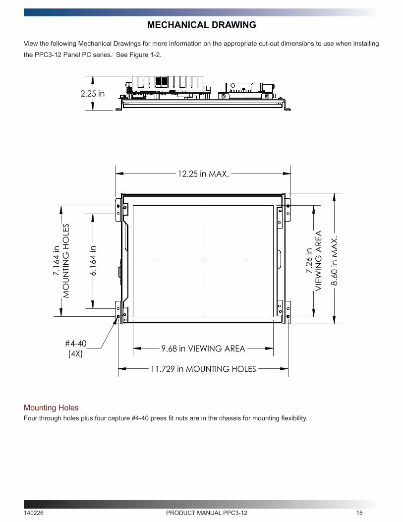
View the following Mechanical Drawings for more information on the appropriate cut-out dimensions to use when installing
the PPC3-12 Panel PC series. See Figure 1-2.
Four through holes plus four capture #4-40 press fit nuts are in the chassis for mounting flexibility.Mounting Holes
140226 PRODUCT MANUAL PPC3-12 16
SOFTWARE DRIVERS & EXAMPLES
See the WinSystems website.
140226 PRODUCT MANUAL PPC3-12 18
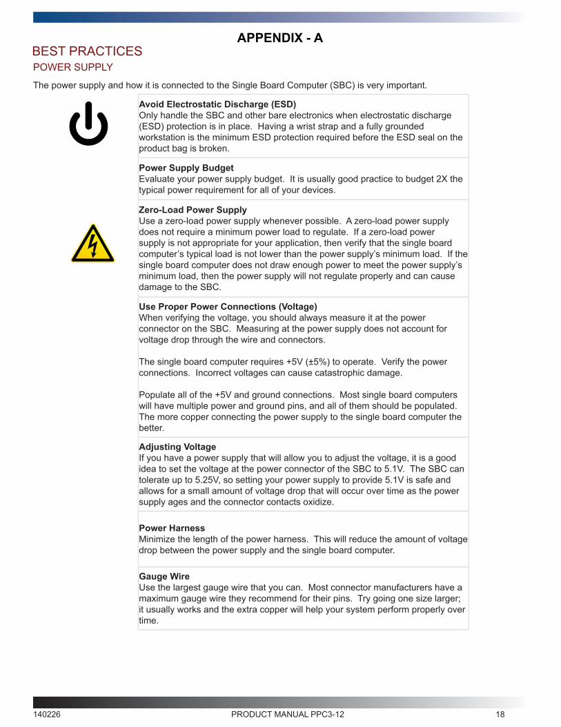
The power supply and how it is connected to the Single Board Computer (SBC) is very important.
Avoid Electrostatic Discharge (ESD)Only handle the SBC and other bare electronics when electrostatic discharge (ESD) protection is in place. Having a wrist strap and a fully grounded workstation is the minimum ESD protection required before the ESD seal on the product bag is broken.
Power Supply BudgetEvaluate your power supply budget. It is usually good practice to budget 2X the typical power requirement for all of your devices.
Zero-Load Power SupplyUse a zero-load power supply whenever possible. A zero-load power supply does not require a minimum power load to regulate. If a zero-load power supply is not appropriate for your application, then verify that the single board computer’s typical load is not lower than the power supply’s minimum load. If the single board computer does not draw enough power to meet the power supply’s minimum load, then the power supply will not regulate properly and can cause damage to the SBC.
Use Proper Power Connections (Voltage)When verifying the voltage, you should always measure it at the power connector on the SBC. Measuring at the power supply does not account for voltage drop through the wire and connectors.
The single board computer requires +5V (±5%) to operate. Verify the power connections. Incorrect voltages can cause catastrophic damage.
Populate all of the +5V and ground connections. Most single board computers will have multiple power and ground pins, and all of them should be populated. The more copper connecting the power supply to the single board computer the better.
Adjusting VoltageIf you have a power supply that will allow you to adjust the voltage, it is a good idea to set the voltage at the power connector of the SBC to 5.1V. The SBC can tolerate up to 5.25V, so setting your power supply to provide 5.1V is safe and allows for a small amount of voltage drop that will occur over time as the power supply ages and the connector contacts oxidize.
Power HarnessMinimize the length of the power harness. This will reduce the amount of voltage drop between the power supply and the single board computer.
Gauge WireUse the largest gauge wire that you can. Most connector manufacturers have a maximum gauge wire they recommend for their pins. Try going one size larger; it usually works and the extra copper will help your system perform properly over time.
APPENDIX - A
POWER SUPPLYBEST PRACTICES
140226 PRODUCT MANUAL PPC3-12 19
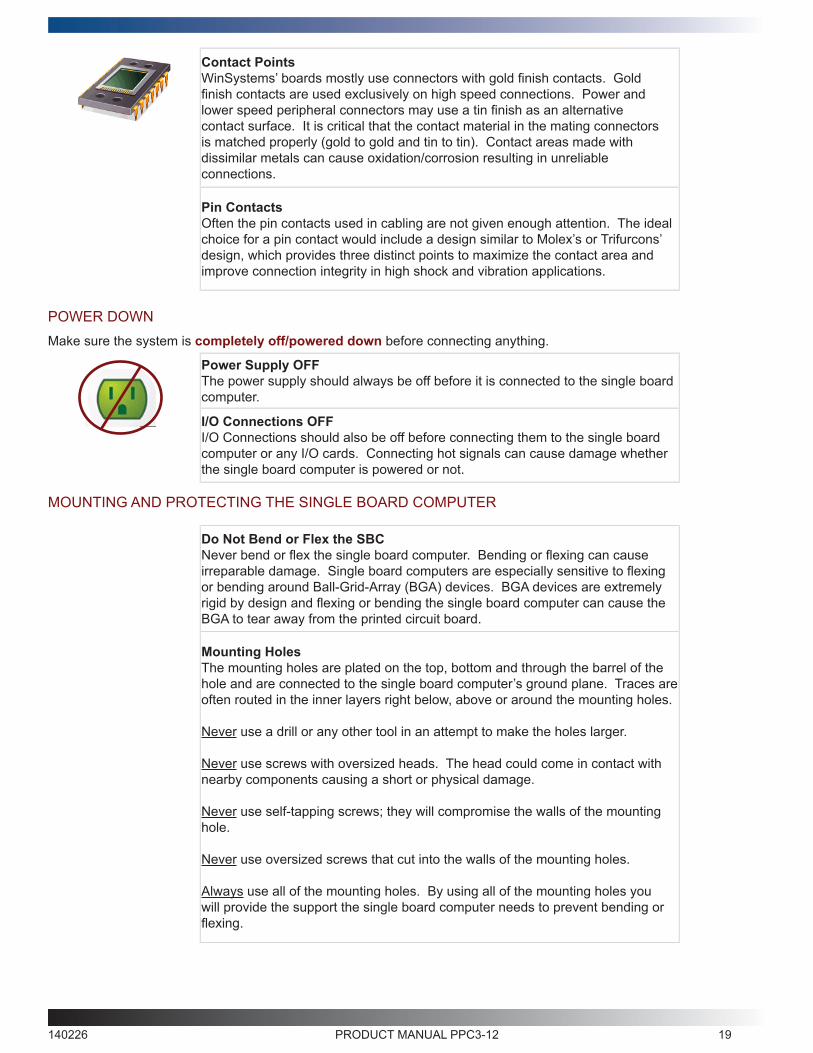
Contact PointsWinSystems’ boards mostly use connectors with gold finish contacts. Gold finish contacts are used exclusively on high speed connections. Power and lower speed peripheral connectors may use a tin finish as an alternative contact surface. It is critical that the contact material in the mating connectors is matched properly (gold to gold and tin to tin). Contact areas made with dissimilar metals can cause oxidation/corrosion resulting in unreliable connections.
Pin ContactsOften the pin contacts used in cabling are not given enough attention. The ideal choice for a pin contact would include a design similar to Molex’s or Trifurcons’ design, which provides three distinct points to maximize the contact area and improve connection integrity in high shock and vibration applications.
POWER DOWNMake sure the system is completely off/powered down before connecting anything.
Power Supply OFFThe power supply should always be off before it is connected to the single board computer.
I/O Connections OFFI/O Connections should also be off before connecting them to the single board computer or any I/O cards. Connecting hot signals can cause damage whether the single board computer is powered or not.
MOUNTING AND PROTECTING THE SINGLE BOARD COMPUTER
Do Not Bend or Flex the SBCNever bend or flex the single board computer. Bending or flexing can cause irreparable damage. Single board computers are especially sensitive to flexing or bending around Ball-Grid-Array (BGA) devices. BGA devices are extremely rigid by design and flexing or bending the single board computer can cause the BGA to tear away from the printed circuit board.
Mounting HolesThe mounting holes are plated on the top, bottom and through the barrel of the hole and are connected to the single board computer’s ground plane. Traces are often routed in the inner layers right below, above or around the mounting holes.
Never use a drill or any other tool in an attempt to make the holes larger.
Never use screws with oversized heads. The head could come in contact with nearby components causing a short or physical damage.
Never use self-tapping screws; they will compromise the walls of the mounting hole.
Never use oversized screws that cut into the walls of the mounting holes.
Always use all of the mounting holes. By using all of the mounting holes you will provide the support the single board computer needs to prevent bending or flexing.

140226 PRODUCT MANUAL PPC3-12 20
MOUNTING AND PROTECTING THE SINGLE BOARD COMPUTER (continued)
Plug or Unplug Connectors Only on Fully Mounted BoardsNever plug or unplug connectors on a board that is not fully mounted. Many of the connectors fit rather tightly and the force needed to plug or unplug them could cause the single board computer to be flexed.
Avoid cutting of the SBCNever use star washers or any fastening hardware that will cut into the single board computer.
Avoid Overtightening of Mounting HardwareCausing the area around the mounting holes to compress could damage interlayer traces around the mouting holes.
Use Appropriate ToolsAlways use tools that are appropriate for working with small hardware. Large tools can damage components around the mounting holes.
Placing the SBC on Mounting StandoffsBe careful when placing the single board computer on the mounting standoffs. Sliding the board around until the standoffs are visible from the top can cause component damage on the bottom of the single board computer.
Avoid Conductive SurfacesNever allow the single board computer to be placed on a conductive surface. Almost all single board computers use a battery to backup the clock-calendar and CMOS memory. A conductive surface such as a metal bench can short the battery causing premature failure.
ADDING PC/104 BOARDS TO YOUR STACKBe careful when adding PC/104 boards to your stack.
Never allow the power to be turned on when a PC/104 board has been improperly plugged onto the stack. It is possible to misalign the PC/104 card and leave a row of pins on the end or down the long side hanging out of the connector. If power is applied with these pins misaligned, it will cause the I/O board to be damaged beyond repair.

140226 PRODUCT MANUAL PPC3-12 21
OPERATIONS / PRODUCT MANUALSEvery single board computer has an operations manual or product manual.
Manual UpdatesOperations/Product Manuals are updated often. Periodicially check the WinSystems website (http://www.winsystems.com) for revisions.
Check PinoutsAlways check the pinout and connector locations in the manual before plugging in a cable. Many single board computers will have identical headers for different functions and plugging a cable into the wrong header can have disastrous results.
Contact an Applications Engineer with questionsIf a diagram or chart in a manual does not seem to match your board, or if you have additional questions, contact your Applications Engineer.
140226 PRODUCT MANUAL PPC3-12 22
WARRANTY INFORMATION
WinSystems warrants to Customer that for a period of two (2) years from the date of shipment any Products and Software
purchased or licensed hereunder which have been developed or manufactured by WinSystems shall be free of any
material defects and shall perform substantially in accordance with WinSystems’ specifications therefore. With respect
to any Products or Software purchased or licensed hereunder which have been developed or manufactured by others,
WinSystems shall transfer and assign to Customer any warranty of such manufacturer or developer held by WinSystems,
provided that the warranty, if any, may be assigned. Notwithstanding anything herein to the contrary, this warranty granted
by WinSystems to the Customer shall be for the sole benefit of the Customer, and may not be assigned, transferred or
conveyed to any third party. The sole obligation of WinSystems for any breach of warranty contained herein shall be, at its
option, either (i) to repair or replace at its expense any materially defective Products or Software, or (ii) to take back such
Products and Software and refund the Customer the purchase price and any license fees paid for the same. Customer
shall pay all freight, duty, broker’s fees, insurance charges for the return of any Products or Software to WinSystems
under this warranty. WinSystems shall pay freight and insurance charges for any repaired or replaced Products or
Software thereafter delivered to Customer within the United States. All fees and costs for shipment outside of the United
States shall be paid by Customer. The foregoing warranty shall not apply to any Products of Software which have been
subject to abuse, misuse, vandalism, accidents, alteration, neglect, unauthorized repair or improper installations.
THERE ARE NO WARRANTIES BY WINSYSTEMS EXCEPT AS STATED HEREIN, THERE ARE NO OTHER
WARRANTIES EXPRESS OR IMPLIED INCLUDING, BUT NOT LIMITED TO, THE IMPLIED WARRANTIES OF
MERCHANTABILITY AND FITNESS FOR A PARTICULAR PURPOSE, IN NO EVENT SHALL WINSYSTEMS BE LIABLE
FOR CONSEQUENTIAL, INCIDENTAL OR SPECIAL DAMAGES INCLUDING, BUT NOT LIMITED TO, DAMAGES
FOR LOSS OF DATA, PROFITS OR GOODWILL. WINSYSTEMS’ MAXIMUM LIABILITY FOR ANY BREACH OF
THIS AGREEMENT OR OTHER CLAIM RELATED TO ANY PRODUCTS, SOFTWARE, OR THE SUBJECT MATTER
HEREOF, SHALL NOT EXCEED THE PURCHASE PRICE OR LICENSE FEE PAID BY CUSTOMER TO WINSYSTEMS
FOR THE PRODUCTS OR SOFTWARE OR PORTION THEREOF TO WHICH SUCH BREACH OR CLAIM PERTAINS.
WARRANTY SERVICE1. To obtain service under this warranty, obtain a return authorization number. In the United States, contact the
WinSystems’ Service Center for a return authorization number. Outside the United States, contact your local sales agent
for a return authorization number.
2. You must send the product postage prepaid and insured. You must enclose the products in an anti-static bag
to protect from damage by static electricity. WinSystems is not responsible for damage to the product due to static
electricity.
(http://www.winsystems.com/warranty.cfm)


![PPC3™ Pressure Controller/Calibrator - Fluke Caldownload.flukecal.com/pub/literature/Manual_PPC3.pdf · PPC3™ Pressure Controller/Calibrator - Fluke Cal ... a [ ] ). < >](https://img.pdfslide.us/doc/110x75/5b9f235309d3f204248cc017/ppc3-pressure-controllercalibrator-fluke-ppc3-pressure-controllercalibrator.jpg)