Embed Size (px)
Citation preview

INGERSOLL RAND COMPANY LTD209 NORTH MAIN STREET - BRYAN, OHIO 43506 (800) 495-0276 FAX (800) 892-6276 © 2017 CCN 15235534
arozone.com
OPERATOR’S MANUAL PP30A-XXX-XXXINCLUDING: OPERATION, INSTALLATION AND MAINTENANCE RELEASED: 10-17-05
REVISED: 5-19-17(REV: F)
3" DRY POWDER DIAPHRAGM PUMP1:1 RATIO (METALLIC)
READ THIS MANUAL CAREFULLY BEFORE INSTALLING,OPERATING OR SERVICING THIS EQUIPMENT.
It is the responsibility of the employer to place this information in the hands of the operator. Keep for future reference.
SERVICE KITSRefer to Model Description Chart to match the pump mate-rial options.7102 Valve Kit for repair of H254PS control valve.104255 for repair of P39124-100 Filter / Regulator.118597-2 Spool Kit for repair of A212PD 4-way alpha valve.637303-XX for Fluid Section repair (see page 6). NOTE: This kit also contains several air motor seals which will need to be replaced.637421 for Air Section repair (see page 8).637374-7 Major Air Valve assembly (see page 9).
PUMP DATAModels . . . . . . . . . . . . . see Model Description Chart for “-XXX”Pump Type . . . . . . . . . Metallic, Dry Powder, Diaphragm PumpMaterial . . . . . . . . . . . . see Model Description ChartSpecific Application for pumping powders up to 50 lb. / ft3
Weight . . . PP30A-XAX-AAA . . . . . . . . . . 137.5 lbs (62.4 kgs) PP30A-XSX-AAA . . . . . . . . . . 236.8 lbs (107.4 kgs)Maximum Air Inlet Pressure . . . . . . . . 50 psig (3.4 bar)Maximum Fluidizing Pressure . . . . . . 100 psig (6.9 bar)Maximum Particle Size . . . . . . . . . . . . . 3/8” dia. (9.5 mm)Maximum Temperature Limits (diaphragm / ball / seat
materials)Nitrile . . . . . . . . . . . . . . . . . . . . 10° to 180° F (-12° to 82° C)Santoprene® . . . . . . . . . . . . . . -40° to 225° F (-40° to 107° C)PTFE. . . . . . . . . . . . . . . . . . . . . . 40° to 225° F (4° to 107° C)
Dimensional Data . . . . . . . . . . . . . . . . . . . see page 12Mounting Dimension . 10-5/32” x 12-1/16” (258.0 mm x
306.4 mm)Noise Level @ 70 psig, 50 cpm . . . . . . 83.0 dB(A)
Tested with 94085 muffler assembly installed. The pump sound pressure levels published here have been updated to
an Equivalent Continuous Sound Level (LAeq) to meet the intent of ANSI S1.13-1971, CAGI-PNEUROP S5.1 using four microphone locations.
NOTICE: All possible options are shown in the chart, however, certain combinations may not be recommended. Consult a representative or the factory if you have questions concerning availability.
Figure 1
MODEL DESCRIPTION CHART
PP30A - X X X - X X X
Fluid ConnectionA - 3 - 8 NPTF- 1B - 3 - 11 BSP
Ball MaterialA - Santoprene
Fluid Section Service Kit Selection
EXAMPLE: Model #PP30A-AAS-AAAFluid Section Service Kit # 637303-AA
PP30A - XXX - A A A
Ball Diaphragm637303 - X X
Fluid Cap & Manifold MaterialA - AluminumS - Stainless Steel
Diaphragm MaterialA - Santoprene
Seat MaterialA - Santoprene
Hardware MaterialP - Carbon SteelS - Stainless Steel
PP30A-XXX-XXX Powder Pump
PP30A-XAX-AAA PP30A-XSX-AAA
Page 2 of 12 PP30A-XXX-XXX (en)
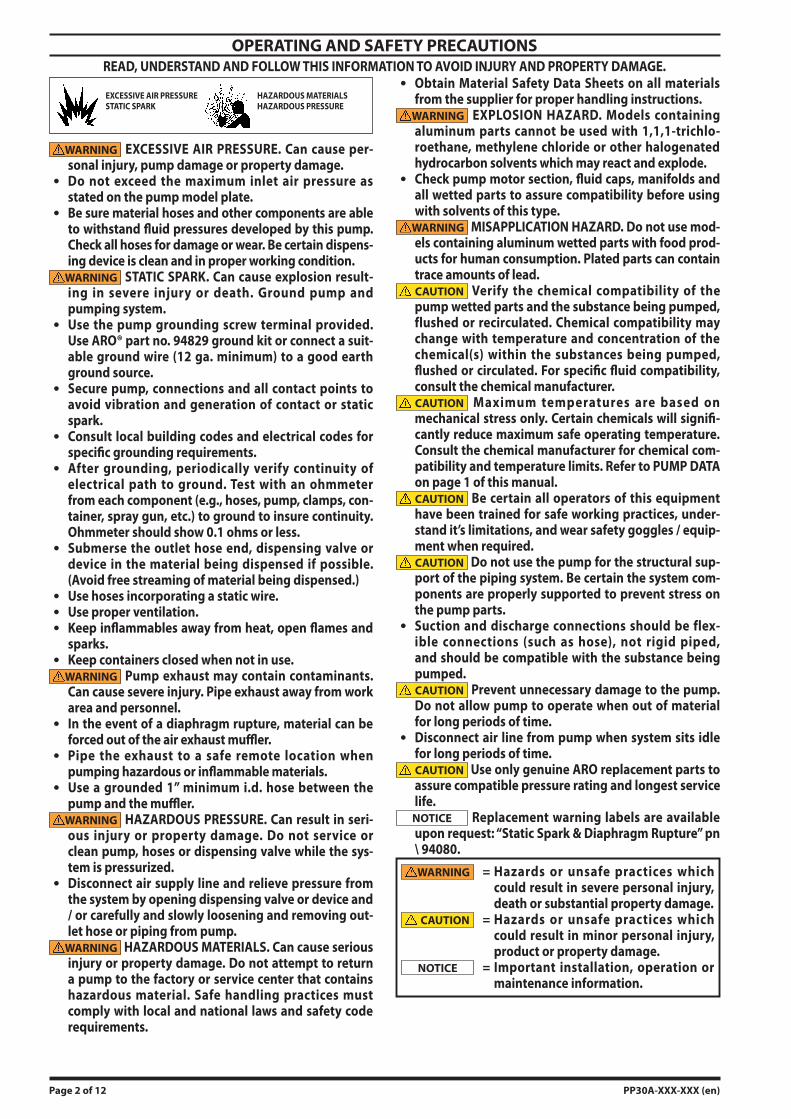
WARNING EXCESSIVE AIR PRESSURE. Can cause per-sonal injury, pump damage or property damage.Do not exceed the maximum inlet air pressure as stated on the pump model plate.Be sure material hoses and other components are able to withstand fluid pressures developed by this pump. Check all hoses for damage or wear. Be certain dispens-ing device is clean and in proper working condition.
WARNING STATIC SPARK. Can cause explosion result-ing in severe injury or death. Ground pump and pumping system.Use the pump grounding screw terminal provided. Use ARO® part no. 94829 ground kit or connect a suit-able ground wire (12 ga. minimum) to a good earth ground source.Secure pump, connections and all contact points to avoid vibration and generation of contact or static spark.Consult local building codes and electrical codes for specific grounding requirements.After grounding, periodically verify continuity of electrical path to ground. Test with an ohmmeter from each component (e.g., hoses, pump, clamps, con-tainer, spray gun, etc.) to ground to insure continuity. Ohmmeter should show 0.1 ohms or less.Submerse the outlet hose end, dispensing valve or device in the material being dispensed if possible. (Avoid free streaming of material being dispensed.)Use hoses incorporating a static wire.Use proper ventilation.Keep inflammables away from heat, open flames and sparks.Keep containers closed when not in use.
WARNING Pump exhaust may contain contaminants. Can cause severe injury. Pipe exhaust away from work area and personnel.In the event of a diaphragm rupture, material can be forced out of the air exhaust muffler.Pipe the exhaust to a safe remote location when pumping hazardous or inflammable materials.Use a grounded 1” minimum i.d. hose between the pump and the muffler.
WARNING HAZARDOUS PRESSURE. Can result in seri-ous injury or property damage. Do not service or clean pump, hoses or dispensing valve while the sys-tem is pressurized.Disconnect air supply line and relieve pressure from the system by opening dispensing valve or device and / or carefully and slowly loosening and removing out-let hose or piping from pump.
WARNING HAZARDOUS MATERIALS. Can cause serious injury or property damage. Do not attempt to return a pump to the factory or service center that contains hazardous material. Safe handling practices must comply with local and national laws and safety code requirements.
OPERATING AND SAFETY PRECAUTIONSREAD, UNDERSTAND AND FOLLOW THIS INFORMATION TO AVOID INJURY AND PROPERTY DAMAGE.
Obtain Material Safety Data Sheets on all materials from the supplier for proper handling instructions.
WARNING EXPLOSION HAZARD. Models containing aluminum parts cannot be used with 1,1,1-trichlo-roethane, methylene chloride or other halogenated hydrocarbon solvents which may react and explode.Check pump motor section, fluid caps, manifolds and all wetted parts to assure compatibility before using with solvents of this type.
WARNING MISAPPLICATION HAZARD. Do not use mod-els containing aluminum wetted parts with food prod-ucts for human consumption. Plated parts can contain trace amounts of lead.CAUTION Verify the chemical compatibility of the pump wetted parts and the substance being pumped, flushed or recirculated. Chemical compatibility may change with temperature and concentration of the chemical(s) within the substances being pumped, flushed or circulated. For specific fluid compatibility, consult the chemical manufacturer.CAUTION Maximum temperatures are based on mechanical stress only. Certain chemicals will signifi-cantly reduce maximum safe operating temperature. Consult the chemical manufacturer for chemical com-patibility and temperature limits. Refer to PUMP DATA on page 1 of this manual.CAUTION Be certain all operators of this equipment have been trained for safe working practices, under-stand it’s limitations, and wear safety goggles / equip-ment when required.CAUTION Do not use the pump for the structural sup-port of the piping system. Be certain the system com-ponents are properly supported to prevent stress on the pump parts.Suction and discharge connections should be flex-ible connections (such as hose), not rigid piped, and should be compatible with the substance being pumped.CAUTION Prevent unnecessary damage to the pump. Do not allow pump to operate when out of material for long periods of time.Disconnect air line from pump when system sits idle for long periods of time.CAUTION Use only genuine ARO replacement parts to assure compatible pressure rating and longest service life.
NOTICE Replacement warning labels are available upon request: “Static Spark & Diaphragm Rupture” pn \ 94080.WARNING = Hazards or unsafe practices which
could result in severe personal injury, death or substantial property damage.
CAUTION = Hazards or unsafe practices which could result in minor personal injury, product or property damage.
NOTICE = Important installation, operation or maintenance information.
EXCESSIVE AIR PRESSURESTATIC SPARK
HAZARDOUS MATERIALSHAZARDOUS PRESSURE
PP30A-XXX-XXX (en) Page 3 of 12
pump. The material inlet supply tubing should not be too small or restrictive, which will inhibit material flow. The outlet material volume is governed not only by the air supply, but also by the material volume available at the inlet.Air supply provided should be filtered to provide clean, dry air. A filter capable of filtering out particles larger than 40 microns should be used on the air supply. There is no lubrication required other than the “O” ring lubricant which is applied during assembly or repair.If lubricated air is present, make sure that it is compatible with the “O” rings and seals in the air motor section of the pump.
NOTE: When using air for powder fluidization, make sure it is filtered and very dry.
INSTALLATIONWARNING THE PUMPING SYSTEM MUST BE GROUND-ED TO PREVENT STATIC DISCHARGE. THIS INCLUDES THE PUMP AND ALL INPUT AND OUTPUT SUPPLY LINES AND RELATED SYSTEM DEVICES AND ACCESSO-RIES. FAILURE TO DO SO CAN RESULT IN EXPLOSION AND SERIOUS PERSONAL INJURY.
SYSTEM GROUNDINGConsult local building codes and electrical codes for specific requirements.Must comply with all applicable Local and National codes for such applications.Grounding is accomplished through the ground lug and strap provided on the pump. Keep the grounding strap as short as possible.Safe operating conditions are the responsibility of the installer and operator.Secure the diaphragm pump legs to a suitable surface to avoid damage by excessive vibration.
OPERATING INSTRUCTIONSSTART-UP
NOTE: PRIOR TO START-UP, MAKE SURE THE GROUNDING INSTRUCTIONS WERE FOLLOWED.
Connect air supply to (263) main air supply control valve (30 - 40 psig / 2.1 - 2.8 bar).Turn the air on.Attach air (or gas) to (248) filter / regulator. CAUTION Do not apply excessive Fluidization Gas*
Pressure (refer to note under “Theroy Of Opetration”).4. Verify that the (253) flow control is fully open.5. At (248), turn on air (or inert gas) supply. There will be a
3 to 8 second time delay, during which the pump will be fluidizing any powder left in the pump from an earlier dispense. This time delay will occur on all start-ups.
OPERATION AND ADJUSTMENTNOTE: Powder type materials can vary in flow-ability and the same settings may not work universally. Factors such as den-sity and humidity can require changing the mixture of flow rate and fluidization air and some experimenting should be expected.IMPORTANT: DO NOT TURN FILTER / REGULATOR (248) OFF.Positive air (or gas) pressure must be supplied to the filter / regulator to allow the pump to function. Powder will accu-mulate in the fluid caps if the pump is not allowed to expel
1.
2.3.
GENERAL DESCRIPTIONThe ARO diaphragm pump offers high volume delivery even at low air pressure and a broad range of material compat-ibility options available. Refer to the model and option chart. ARO pumps feature stall resistant design, modular air motor / fluid sections.Air operated double diaphragm pumps utilize a pressure dif-ferential in the air chambers to alternately create suction and positive fluid pressure in the fluid chambers, valve checks insure a positive flow of fluid.This diaphragm pump was developed to address the unique problems associated with pumping dry powders, which can “pack out” inside the pump fluid chambers, if not kept in a semi-fluid state.This system incorporates the use of special valves to intro-duce air or inert gas* into the fluid chambers simultaneously to a pumping cycle in a timed sequence which keeps the powder in a fluidized state during the transfer process.
THEORY OF OPERATIONThe main air distribution valve (252) is a double pilot actu-ated four-way valve. It is a slave to the pump major air valve.The distribution valve recognizes the signal from two pump major air valve (259) ports (air dumps). These signals are con-verted into alternating output pressure distributions, which are injected into the fluid chambers during the pumping cy-cle to fluidize the powder as the diaphragm moves through the discharge stroke.The flow of air supplied to the fluid chamber is controlled by the (248) filter / regulator. Under normal operating condi-tions, this is the primary control.When air is supplied to the filter / regulator (248), the dis-tribution valve directs the flow of air into the fluid chamber that will dispense first for 3 to 8 seconds. The time delay then supplies the start signal to open the main pump air supply valve. When the pump diaphragm reaches the end of the discharge stroke, it reverses direction. The distribution valve then shifts and shuts off the fluidizing air to the first fluid chamber as it applies a burst of air to the second fluid cham-ber and fluidizes the powder in the second chamber.The air induction orifice (76) increases the air velocity prior to injection point because of the orifice and it prevents clog-ging of the injector feed line.NOTE: The restart valve (258) is a bleed valve which will stop the pump and then restart the pump by re-initiating the time delay cycle.*NOTE: Use of other gases: Using only a gas to operate a 3” pump can be rather expensive because of the high volume needed. Separate air / gas inputs allow the fluidizing feature of this pump to utilize special inert gas, such as Nitrogen or Argon (air), if necessary and still allow use of standard com-pressed shop air for the pumping function.The ability to introduce special gas also means special ma-terials could be injected through the fluidization lines. Ap-plications may include such materials as colorants, foaming agents, additives, neutralizers, etc.
AIR AND LUBE REQUIREMENTSWARNING EXCESSIVE AIR PRESSURE. Can cause pump damage, personal injury or property damage. The pump air supply must be limited to 50 p.s.i.g. (3.4 bar) maximum inlet air pressure.The air supply line or hose to the pump should be ad-equately sized to carry a sufficient volume of air to the

Page 4 of 12 PP30A-XXX-XXX (en)
excess material before the pump shuts down. Restart can compress some powders to a solid that may cause the pump to fail. The pump should cycle until most of the powder has been purged before it is shut down.
Calibration procedure on initial start-up:NOTE: Once these parameters are established for your spe-cific application, they should not need to be changed.
Turn the flow and pressure on the (248) filter / regulator all the way up.Slowly decrease pressure and flow until pump begins to labor (work harder).Increase pressure and flow back to a point where the pump begins to run smoothly. This will optimize the air-to-powder mix and will help to establish the most effi-cient working parameters.
If the pump should begin to cycle slowly (bog down), the powder can be purged by depressing restart button. This will stop the pump and restart the aeration cycle and allow time to increase air flow to the aeration ports for proper material movement.
IMPORTANTSHUT DOWN PROCEDURE - TO HELP PREVENT PACK-OUTIt is good operating practice to dry cycle the pump 5 - 10 seconds at the end of each dispense cycle. This can be ac-complished by closing off the powder source at the suction of the pump or pull wand from material. This will help clear the pump chambers of any residual powder.
CAUTION Failure to insure proper fluidization can result in internal parts breakage and pump failure.
MAINTENANCERefer to the part views and descriptions as provided on page 6 through 11 for parts identification and Service Kit informa-tion.
Keep good records of service activity and include pump in preventive maintenance program.Certain ARO “Smart Parts” are indicated which should be available for fast repair and reduction of down time.Service kits are divided to service two separate dia-phragm pump functions: 1. AIR SECTION, 2. FLUID SEC-TION. The FLUID SECTION is divided further to match typical part MATERIAL OPTIONS.Provide a clean work surface to protect sensitive internal moving parts from contamination from dirt and foreign matter during service disassembly and reassembly.Before disassembling, empty captured material in the outlet manifold by turning the pump upside down to drain material from the pump.
1.
2.
3.
SCHEMATIC CIRCUIT
Figure 2
A212PD12 14
4 2
Left 2
95077
Air / Nitrogen
Right 44
1
2
Exh 241301
2
H254PS94977
3
CP10-BCP10-B
119309-103
TROUBLESHOOTINGProduct discharged from exhaust outlet.
Check for diaphragm rupture.Check tightness of (14) diaphragm screw.
Motor blows air or stalls.Check (176) check valve for damage or wear.Check for restrictions in valve / exhaust.
Low output volume, erratic flow, or no flow.Check air supply.Check for plugged outlet hose.Check for kinked (restrictive) outlet material hose.Check for kinked (restrictive) or collapsed inlet material hose.Suction hose must be a non-collapsing type, conductive and capable of pulling a high vacuum (up to 30” mer-cury).Check all joints on the inlet manifolds and suction con-nections. Connection must be air tight.Inspect the pump for solid objects lodged in the dia-phragm chamber or the seat area.
Loctite® and 242® are registered trademarks of Henkel Loctite Corporation ARO® is a registered trademark of Ingersoll-Rand Company Santoprene® is a registered trademark of Monsanto Company, licensed to Advanced Elastomer Systems, L.P. 271™ is a trademark of Henkel Loctite Corporation
Lubriplate® is a registered trademark of Lubriplate Division (Fiske Brothers Refining Company)
PP30A-XXX-XXX (en) Page 5 of 12
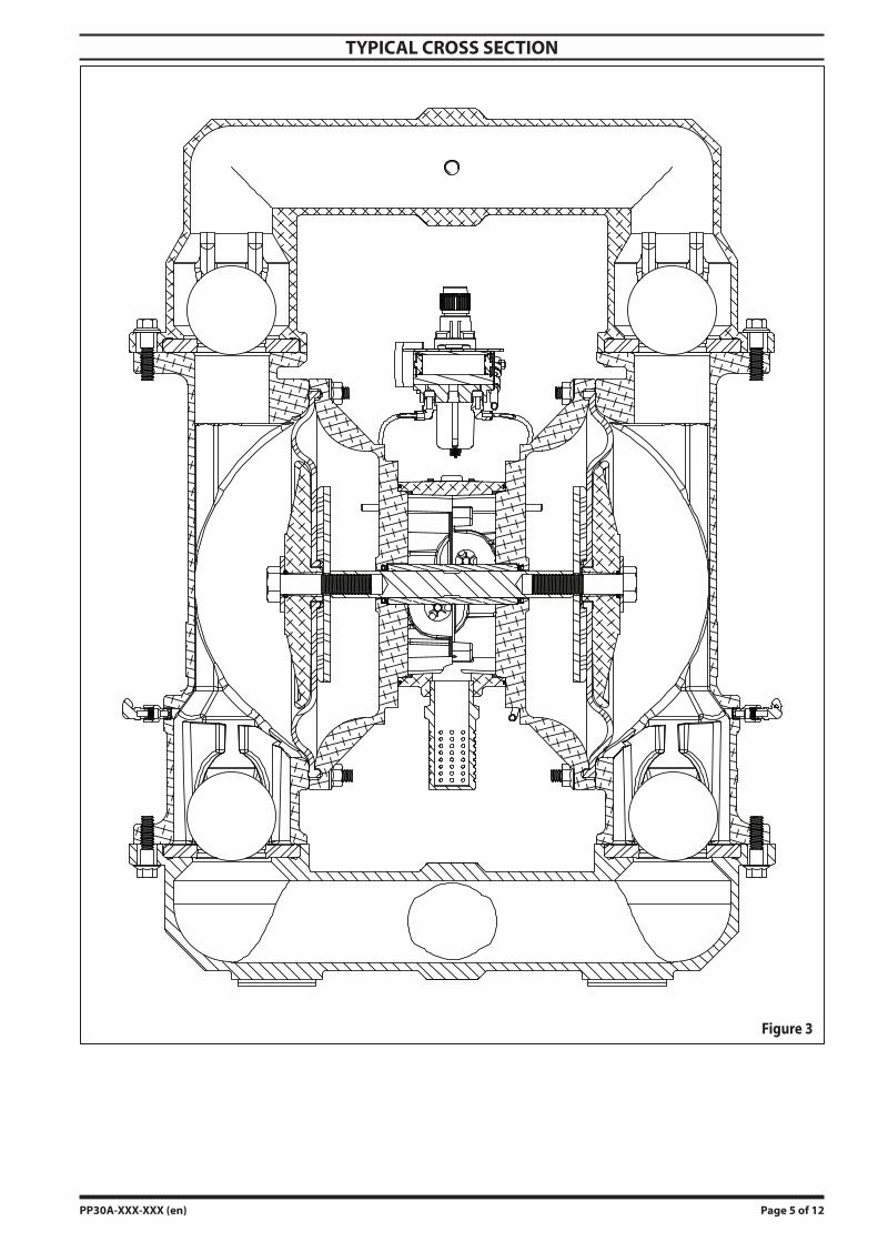
TYPICAL CROSS SECTION
Figure 3

Page 6 of 12 PP30A-XXX-XXX (en)
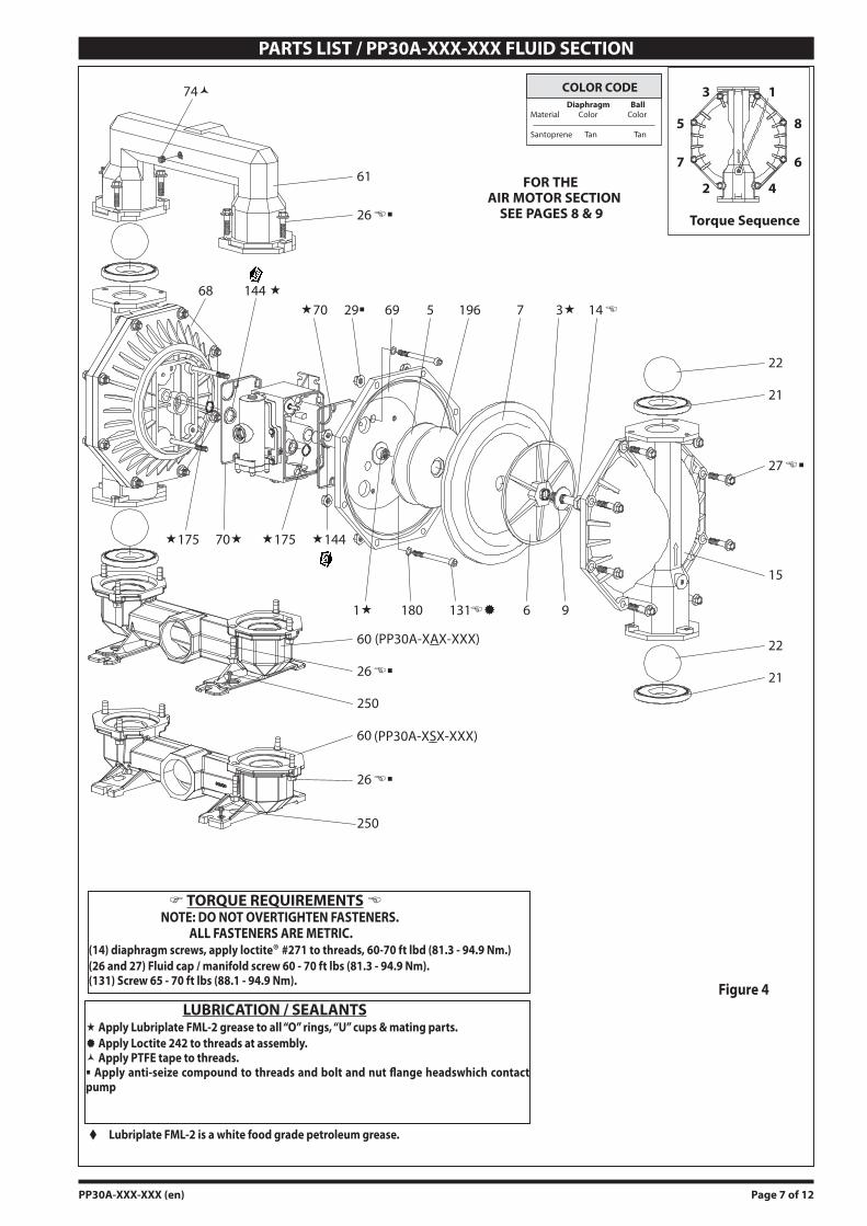
PARTS LIST / PP30A-XXX-XXX FLUID SECTION 637303-XX fluid section service kits include: Balls (item 22), diaphragms (item 7), and items 3, 70, 144, 175, 196 (listed below) plus
items 174 and 94276 Lubriplate® FML-2 grease (page 8).
MATERIAL CODE
[A] = Aluminum[B] = Nitrile[C] = Carbon Steel[Co] = Copper[Sp] = Santoprene[SS] = Stainless Steel[T] = PTFE
PARTS LISTItem Description (size) Qty Part No. [Mtl]
1 Rod (1) 94984 [C] 3 “O” Ring (1/8” x 1” o.d.) (2) Y328-210 [T]
5 Back-Up Washer (2) 94831-1 [C]9 Washer (3/16” i.d. x 2” o.d. x 5/32”) (2) Y13-12-T [SS]
14 Cap Screw (3/4” - 16 x 3-1/4”) (2) Y5-134-T [SS]68 Air Cap (1) 94030-4 [A]69 Air Cap (1) 94030-5 [A]
70 Gasket (2) 94100 [B]74 Pipe Plug (1/4 - 18 N.P.T. x 7/16”) (1) Y17-51-N [C]
Item Description (size) Qty Part No. [Mtl]79 Ground Kit Assembly (not
shown)(1) 94829 - - -
131 Screw (M10 x 1.5 - 6g x 120 mm) (4) 94531 [C] 144 “U” Cup (3/16” x 1-3/8” o.d.) (2) Y186-51 [B] 175 “O” Ring (3/32” x 1” o.d.) (2) Y325-117 [B] 180 Washer (0.406” i.d. x 0.031” thick) (4) 94098 [Co] 196 Cushion (2) 94631 [Sp]
250 Screw, Self-Tapping (1/4” - 14 x 1/2”)
(2) Y334-104-C [C]
SEAT OPTIONSPP30A-XXX-XXX
BALL OPTIONSPP30A-XXX-XXX
DIAPHRAGM OPTIONSPP30A-XXX-XXX
“21” “22” (3-1/4” diameter) “7”-XXX Seat Qty [Mtl] -XXX Ball Qty [Mtl] -XXX Diaphragm Qty [Mtl]-AXX 94104-A (4) [Sp] -XAX 94103-A (4) [Sp] -XXA 94091-A (2) [Sp]
MANIFOLD CONNECTION / FLUID CAP MATERIAL OPTIONS PP30A-XXX-XXXAluminum Stainless Steel
N.P.T. BSP N.P.T. BSPPP30A-AAX-XXX PP30A-BAX-XXX PP30A-ASX-XXX PP30A-BSX-XXX
Item Description (size) Qty Part No. [Mtl] Part No. [Mtl] Part No. [Mtl] Part No. [Mtl]6 Diaphragm Washer (2) 94802 [A] 94802 [A] 94803 [SS] 94803 [SS]
15 Fluid Cap (2) 94768 [A] 94768 [A] 94815 [SS] 94815 [SS]60 Inlet Manifold (1) 94913 [A] 94913-2 [A] 94212-1 [SS] 94212-2 [SS]61 Outlet Manifold (1) 94766 [A] 94766-2 [A] 94818 [SS] 94818-2 [SS]
EXTERNAL HARDWARE OPTIONS PP30A-XXX-XXX
PP30A-XXP-XXX PP30A-XXS-XXXItem Description (size) Qty Part No. [Mtl] Part No. [Mtl]
26 Screw (M12 x 1.75 - 6g x 45 mm) (12) 94412-1 [C] 94412-2 [SS]27 Screw (M12 x 1.75 - 6g x 60 mm) (16) 94991-1 [C] 94991 [SS]29 Nut (M12 x 1.75 - 6h) (16) 95053-1 [C] 95053 [SS]
FLUID SECTION DISASSEMBLYRemove (61) outlet manifold and (60) inlet manifold.Remove (22) balls and (21) seats.Remove (15) fluid caps. Remove (14) cap screw, (6) diaphragm washer, (7) dia-phragm and (5) back-up washer.
NOTE: Do not scratch or mar the surface of (1) diaphragm rod.
1.2.3.4.
FLUID SECTION REASSEMBLYReassemble in reverse order. Refer to the torque require-ments on page 7.Clean and inspect all parts. Replace worn or damaged parts with new parts as required.Lubricate (1) diaphragm rod and (144) “U” cups with Lu-briplate FML-2 grease (94276 grease packet is included in service kit).Examine torque settings after pump has been re-started and run a while.
Air motor Kit parts, see pages 8 and 9.
PP30A-XXX-XXX (en) Page 7 of 12
LUBRICATION / SEALANTS Apply Lubriplate FML-2 grease to all “O” rings, “U” cups & mating parts. Apply Loctite 242 to threads at assembly. Apply PTFE tape to threads. Apply anti-seize compound to threads and bolt and nut flange headswhich contact pump
TORQUE REQUIREMENTS NOTE: DO NOT OVERTIGHTEN FASTENERS. ALL FASTENERS ARE METRIC.(14) diaphragm screws, apply loctite® #271 to threads, 60-70 ft lbd (81.3 - 94.9 Nm.)(26 and 27) Fluid cap / manifold screw 60 - 70 ft lbs (81.3 - 94.9 Nm).(131) Screw 65 - 70 ft lbs (88.1 - 94.9 Nm).
PARTS LIST / PP30A-XXX-XXX FLUID SECTION
Figure 4
Lubriplate FML-2 is a white food grade petroleum grease.
COLOR CODE
15
FOR THEAIR MOTOR SECTION
SEE PAGES 8 & 9
6875
21
180 131��
�17570�
69
27��
�70
22
�144
3� 14�
9
144 �
Diaphragm BallMaterial Color Color
Santoprene Tan Tan8
6
4
1
2
3
5
7
Torque Sequence
22
21
61
26��
26��
250
1�
29�
�175
74�
60 (PP30A-XAX-XXX)
26��
60 (PP30A-XSX-XXX)
250
196
6
Page 8 of 12 PP30A-XXX-XXX (en)
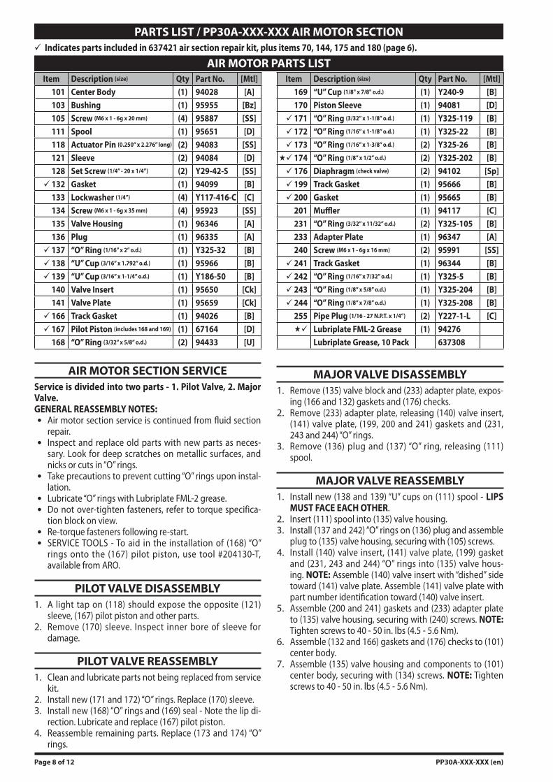
PARTS LIST / PP30A-XXX-XXX AIR MOTOR SECTION Indicates parts included in 637421 air section repair kit, plus items 70, 144, 175 and 180 (page 6).
AIR MOTOR SECTION SERVICEService is divided into two parts - 1. Pilot Valve, 2. Major Valve.GENERAL REASSEMBLY NOTES:
Air motor section service is continued from fluid section repair.Inspect and replace old parts with new parts as neces-sary. Look for deep scratches on metallic surfaces, and nicks or cuts in “O” rings.Take precautions to prevent cutting “O” rings upon instal-lation.Lubricate “O” rings with Lubriplate FML-2 grease.Do not over-tighten fasteners, refer to torque specifica-tion block on view.Re-torque fasteners following re-start.SERVICE TOOLS - To aid in the installation of (168) “O” rings onto the (167) pilot piston, use tool #204130-T, available from ARO.
PILOT VALVE DISASSEMBLYA light tap on (118) should expose the opposite (121) sleeve, (167) pilot piston and other parts.Remove (170) sleeve. Inspect inner bore of sleeve for damage.
PILOT VALVE REASSEMBLYClean and lubricate parts not being replaced from service kit.Install new (171 and 172) “O” rings. Replace (170) sleeve.Install new (168) “O” rings and (169) seal - Note the lip di-rection. Lubricate and replace (167) pilot piston.Reassemble remaining parts. Replace (173 and 174) “O” rings.
1.
2.
1.
2.3.
4.
MAJOR VALVE DISASSEMBLYRemove (135) valve block and (233) adapter plate, expos-ing (166 and 132) gaskets and (176) checks.Remove (233) adapter plate, releasing (140) valve insert, (141) valve plate, (199, 200 and 241) gaskets and (231, 243 and 244) “O” rings.Remove (136) plug and (137) “O” ring, releasing (111) spool.
MAJOR VALVE REASSEMBLYInstall new (138 and 139) “U” cups on (111) spool - LIPS MUST FACE EACH OTHER.Insert (111) spool into (135) valve housing.Install (137 and 242) “O” rings on (136) plug and assemble plug to (135) valve housing, securing with (105) screws.Install (140) valve insert, (141) valve plate, (199) gasket and (231, 243 and 244) “O” rings into (135) valve hous-ing. NOTE: Assemble (140) valve insert with “dished” side toward (141) valve plate. Assemble (141) valve plate with part number identification toward (140) valve insert.Assemble (200 and 241) gaskets and (233) adapter plate to (135) valve housing, securing with (240) screws. NOTE: Tighten screws to 40 - 50 in. lbs (4.5 - 5.6 Nm).Assemble (132 and 166) gaskets and (176) checks to (101) center body.Assemble (135) valve housing and components to (101) center body, securing with (134) screws. NOTE: Tighten screws to 40 - 50 in. lbs (4.5 - 5.6 Nm).
1.
2.
3.
1.
2.3.
4.
5.
6.
7.
AIR MOTOR PARTS LISTItem Description (size) Qty Part No. [Mtl]
101 Center Body (1) 94028 [A]103 Bushing (1) 95955 [Bz]105 Screw (M6 x 1 - 6g x 20 mm) (4) 95887 [SS]111 Spool (1) 95651 [D]118 Actuator Pin (0.250” x 2.276” long) (2) 94083 [SS]121 Sleeve (2) 94084 [D]128 Set Screw (1/4” - 20 x 1/4”) (2) Y29-42-S [SS] 132 Gasket (1) 94099 [B]
133 Lockwasher (1/4”) (4) Y117-416-C [C]134 Screw (M6 x 1 - 6g x 35 mm) (4) 95923 [SS]135 Valve Housing (1) 96346 [A]136 Plug (1) 96335 [A] 137 “O” Ring (1/16” x 2” o.d.) (1) Y325-32 [B] 138 “U” Cup (3/16” x 1.792” o.d.) (1) 95966 [B] 139 “U” Cup (3/16” x 1-1/4” o.d.) (1) Y186-50 [B]
140 Valve Insert (1) 95650 [Ck]141 Valve Plate (1) 95659 [Ck] 166 Track Gasket (1) 94026 [B] 167 Pilot Piston (includes 168 and 169) (1) 67164 [D]
168 “O” Ring (3/32” x 5/8” o.d.) (2) 94433 [U]
Item Description (size) Qty Part No. [Mtl]169 “U” Cup (1/8" x 7/8" o.d.) (1) Y240-9 [B]170 Piston Sleeve (1) 94081 [D] 171 “O” Ring (3/32” x 1-1/8” o.d.) (1) Y325-119 [B] 172 “O” Ring (1/16” x 1-1/8” o.d.) (1) Y325-22 [B] 173 “O” Ring (1/16” x 1-3/8” o.d.) (2) Y325-26 [B] 174 “O” Ring (1/8” x 1/2” o.d.) (2) Y325-202 [B] 176 Diaphragm (check valve) (2) 94102 [Sp] 199 Track Gasket (1) 95666 [B] 200 Gasket (1) 95665 [B]
201 Muffler (1) 94117 [C]231 “O” Ring (3/32” x 11/32” o.d.) (2) Y325-105 [B]233 Adapter Plate (1) 96347 [A]240 Screw (M6 x 1 - 6g x 16 mm) (2) 95991 [SS] 241 Track Gasket (1) 96344 [B] 242 “O” Ring (1/16” x 7/32” o.d.) (1) Y325-5 [B] 243 “O” Ring (1/8” x 5/8” o.d.) (1) Y325-204 [B] 244 “O” Ring (1/8” x 7/8” o.d.) (1) Y325-208 [B]
255 Pipe Plug (1/16 - 27 N.P.T. x 1/4”) (2) Y227-1-L [C] Lubriplate FML-2 Grease (1) 94276
Lubriplate Grease, 10 Pack 637308
PP30A-XXX-XXX (en) Page 9 of 12
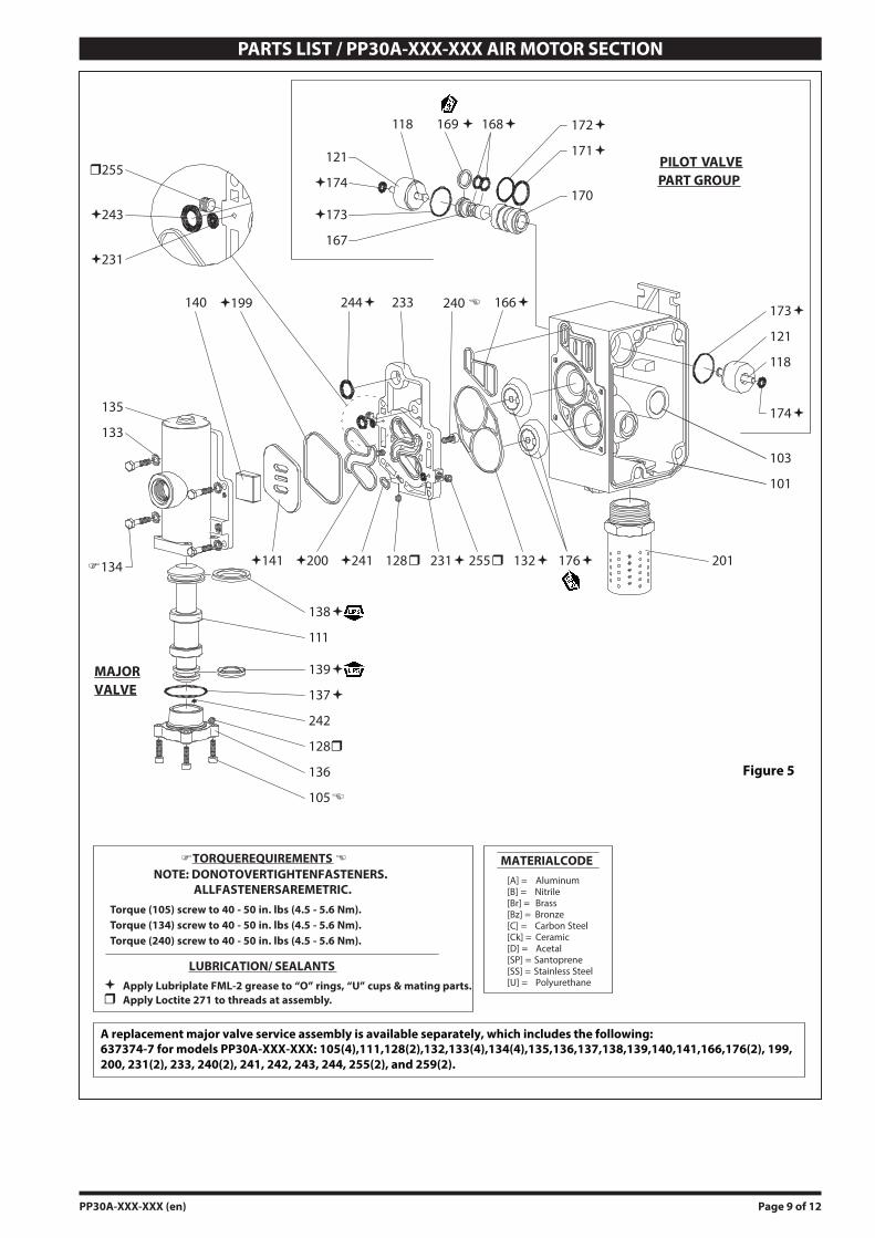
PARTS LIST / PP30A-XXX-XXX AIR MOTOR SECTION
168�
105�
�TORQUEREQUIREMENTS �NOTE: DONOTOVERTIGHTENFASTENERS.
ALLFASTENERSAREMETRIC.
LUBRICATION/ SEALANTS
136
137�
139�
111
138�
135
133
�134
101
103
174�
121
118
173�
169 � 172�
171�
170
167
�173
121
�174
118
166�
132�
244��199140 240 �
128� 176�
PILOT VALVEPART GROUP
MAJORVALVE
Figure 5
128�
233
242
MATERIALCODE[A] = Aluminum[B] = Nitrile[Br] = Brass[Bz] = Bronze[C] = Carbon Steel[Ck] = Ceramic[D] = Acetal[SP] = Santoprene[SS] = Stainless Steel[U] = Polyurethane
201255�231��241�200�141
�255
�231
�243
Torque (105) screw to 40 - 50 in. lbs (4.5 - 5.6 Nm).Torque (134) screw to 40 - 50 in. lbs (4.5 - 5.6 Nm).Torque (240) screw to 40 - 50 in. lbs (4.5 - 5.6 Nm).
� Apply Lubriplate FML-2 grease to “O” rings, “U” cups & mating parts.� Apply Loctite 271 to threads at assembly.
637374-7 for models PP30A-XXX-XXX: 105(4),111,128(2),132,133(4),134(4),135,136,137,138,139,140,141,166,176(2), 199, 200, 231(2), 233, 240(2), 241, 242, 243, 244, 255(2), and 259(2).
A replacement major valve service assembly is available separately, which includes the following:
PP30A-XXX-XXX (en) Page 10 of 12
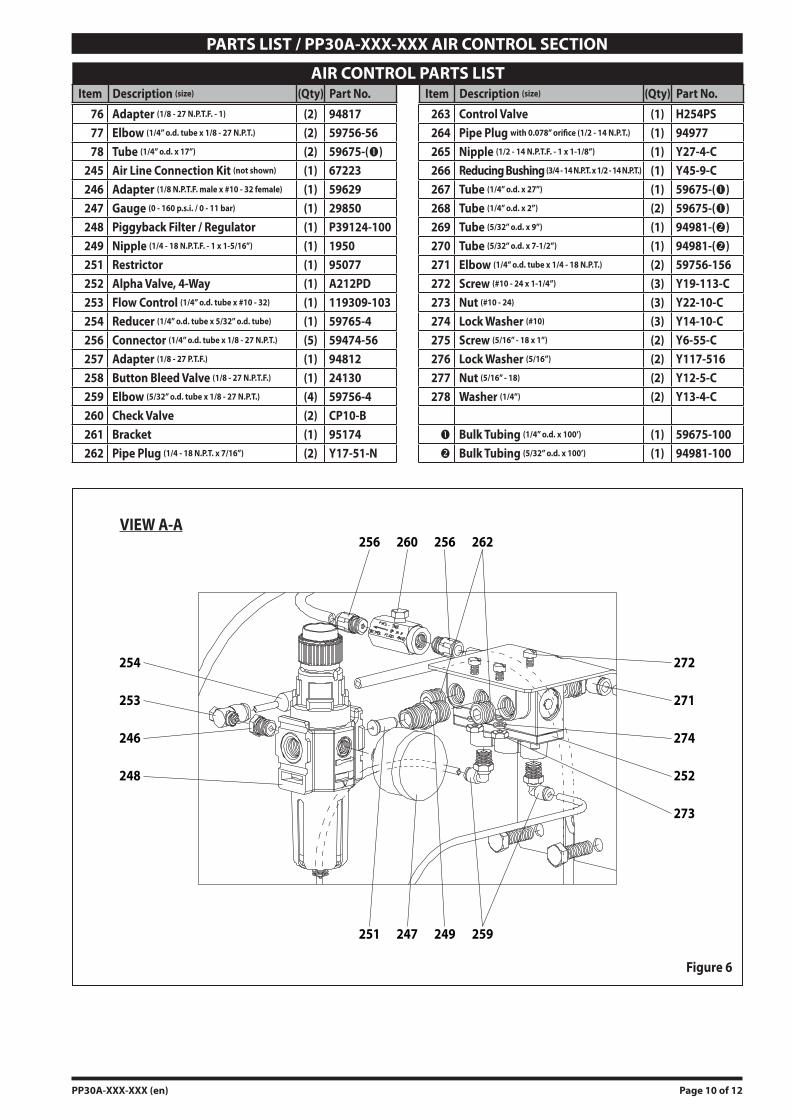
PARTS LIST / PP30A-XXX-XXX AIR CONTROL SECTION
AIR CONTROL PARTS LISTItem Description (size) (Qty) Part No. Item Description (size) (Qty) Part No.
76 Adapter (1/8 - 27 N.P.T.F. - 1) (2) 9481777 Elbow (1/4” o.d. tube x 1/8 - 27 N.P.T.) (2) 59756-5678 Tube (1/4” o.d. x 17”) (2) 59675-()
245 Air Line Connection Kit (not shown) (1) 67223246 Adapter (1/8 N.P.T.F. male x #10 - 32 female) (1) 59629247 Gauge (0 - 160 p.s.i. / 0 - 11 bar) (1) 29850248 Piggyback Filter / Regulator (1) P39124-100249 Nipple (1/4 - 18 N.P.T.F. - 1 x 1-5/16”) (1) 1950251 Restrictor (1) 95077252 Alpha Valve, 4-Way (1) A212PD253 Flow Control (1/4” o.d. tube x #10 - 32) (1) 119309-103254 Reducer (1/4” o.d. tube x 5/32” o.d. tube) (1) 59765-4256 Connector (1/4” o.d. tube x 1/8 - 27 N.P.T.) (5) 59474-56257 Adapter (1/8 - 27 P.T.F.) (1) 94812258 Button Bleed Valve (1/8 - 27 N.P.T.F.) (1) 24130259 Elbow (5/32” o.d. tube x 1/8 - 27 N.P.T.) (4) 59756-4260 Check Valve (2) CP10-B261 Bracket (1) 95174262 Pipe Plug (1/4 - 18 N.P.T. x 7/16”) (2) Y17-51-N
263 Control Valve (1) H254PS264 Pipe Plug with 0.078” orifice (1/2 - 14 N.P.T.) (1) 94977265 Nipple (1/2 - 14 N.P.T.F. - 1 x 1-1/8”) (1) Y27-4-C266 Reducing Bushing (3/4 - 14 N.P.T. x 1/2 - 14 N.P.T.) (1) Y45-9-C267 Tube (1/4” o.d. x 27”) (1) 59675-()268 Tube (1/4” o.d. x 2”) (2) 59675-()269 Tube (5/32” o.d. x 9”) (1) 94981-()270 Tube (5/32” o.d. x 7-1/2”) (1) 94981-()271 Elbow (1/4” o.d. tube x 1/4 - 18 N.P.T.) (2) 59756-156272 Screw (#10 - 24 x 1-1/4”) (3) Y19-113-C273 Nut (#10 - 24) (3) Y22-10-C274 Lock Washer (#10) (3) Y14-10-C275 Screw (5/16” - 18 x 1”) (2) Y6-55-C276 Lock Washer (5/16”) (2) Y117-516277 Nut (5/16” - 18) (2) Y12-5-C278 Washer (1/4”) (2) Y13-4-C
Bulk Tubing (1/4” o.d. x 100’) (1) 59675-100 Bulk Tubing (5/32” o.d. x 100’) (1) 94981-100
VIEW A-A
274
252
271
272
273
246
253
248
254
260256 262256
247 249251 259
Figure 6
Page 11 of 12 PP30A-XXX-XXX (en)
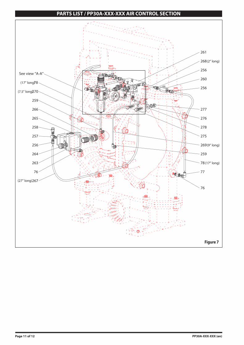
PARTS LIST / PP30A-XXX-XXX AIR CONTROL SECTION
77
76
78 (17” long)
259
269(9” long)
275
278
276
277
256
260
256
268(2” long)
261
257
258
265
266
259
(7.5” long)270
(17” long)78
256
264
263
76
(27” long)267
See view “A-A”
Figure 7

Page 12 of 12 PP30A-XXX-XXX (en)
PN 97999-1137
(Dimensions shown are for reference only, they are displayed in inches and millimeters (mm).
Figure 8
3 - 8 NPTF - 1 (PP30A-AXX-AAA)
Rp 3 (3 - 11 BSP parallel) (PP30A-BXX-AAA)
Inlet
Outlet
AC
K
M
EF
G
HJ
Exhaust Port 1-1/2 - 11-1/2 NPT
L
D
B
PP30A-XSX-AAADimension Aluminum Stainless Steel
A - 24-5/32” (613.4 mm) 23-29/32” (607.0 mm)B - 29-15/16” (760.5 mm) 30” (761.7 mm)C - 12-1/16” (306.4 mm) 12-1/32” (305.3 mm)D - 2-3/8” (60.3 mm) 2-3/4” (69.9 mm)E - 17-19/32” (446.6 mm) 17-19/32” (446.6 mm)F - 15” (381.0 mm) 15” (381.0 mm)G - 32-3/32” (815.0 mm) 32” (812.5 mm)H - 10-5/32” (258.0 mm) 10-5/32” (258.0 mm)J - 11” (279.4 mm) 11-21/32” (296.1 mm)K - 9/16” (14.3 mm) 9/16” (14.3 mm)L - 2-3/4” (69.9 mm) 2-3/4” (69.9 mm)M - 17-3/16” (436.5 mm) 17-21/32” (448.0 mm)N - 22-3/4” (577.3 mm) 23-3/16” (588.7 mm)
N
Air Inlet 1/2 - 14 NPTF
PP30A-XAX-AAA
DIMENSIONAL DATA