Embed Size (px)
Citation preview
A micromechanics-based damage model for the strength prediction of composite laminates
PP Camanho*, JA Mayugo§, P Maimí§, CG Dávila**
*DEMEGI, Faculdade de Engenharia, Universidade do Porto, Portugal §AMADE, University of Girona, Spain
**NASA Langley Research Center, Hampton, VA, U.S.A.
ABSTRACT
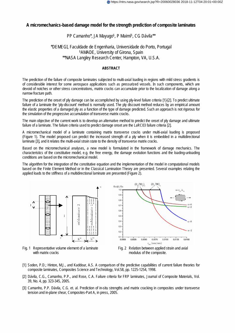
The prediction of the failure of composite laminates subjected to multi-axial loading in regions with mild stress gradients is of considerable interest for some aerospace applications such as pressurized vessels. In such components, which are devoid of notches or other stress concentrations, matrix cracks can accumulate prior to the localization of damage along a narrow fracture path.
The prediction of the onset of ply damage can be accomplished by using ply-level failure criteria [1]-[2]. To predict ultimate failure of a laminate the ‘ply-discount’ method is normally used. The ply discount method reduces by an empirical amount the elastic properties of a damaged ply as a function of the type of damage predicted. Such an approach is not rigorous for the simulation of the progressive accumulation of transverse matrix cracks.
The main objective of the current work is to develop an alternative method to predict the onset of ply damage and ultimate failure of a laminate. The failure criteria used to predict damage onset are the LaRC03 failure criteria [2].
A micromechanical model of a laminate containing matrix transverse cracks under multi-axial loading is proposed (Figure 1). The model proposed can predict the increased strength of a ply when it is embedded in a multidirectional laminate [3], and it relates the multi-axial strain state to the density of transverse matrix cracks.
Based on the micromechanical analyses, a new model is formulated in the framework of damage mechanics. The characteristics of the constitutive model, e.g. the free energy, the damage evolution functions and the loading-unloading conditions are based on the micromechanical model.
The algorithm for the integration of the constitutive equation and the implementation of the model in computational models based on the Finite Element Method or in the Classical Lamination Theory are presented. Several examples relating the applied loads to the stiffness of a multidirectional laminate are presented (Figure 2).
Fig. 1 Representative volume element of a laminate
with matrix cracks Fig. 2 Relation between applied strain and axial
modulus of the composite.
[1] Soden, P.D.; Hinton, M.J., and Kaddour, A.S. A comparison of the predictive capabilities of current failure theories for composite laminates, Composites Science and Technology, Vol.58, pp. 1225-1254, 1998.
[2] Dávila, C.G., Camanho, P.P., and Rose, C.A. Failure criteria for FRP laminates, Journal of Composite Materials, Vol. 39, No. 4, pp. 323-345, 2005.
[3] Camanho, P.P. Dávila, C.G. et. al. Prediction of in-situ strengths and matrix cracking in composites under transverse tension and in-plane shear, Composites-Part A, in press, 2005.
https://ntrs.nasa.gov/search.jsp?R=20060028036 2018-11-12T04:20:01+00:00Z
III European Conference on Computational MechanicsSolids, Structures and Coupled Problems in Engineering
C.A. Mota Soares et.al. (eds.)Lisbon, Portugal, 5–8 June 2006
A MICROMECHANICS-BASED DAMAGE MODEL FOR THESTRENGTH PREDICTION OF COMPOSITE LAMINATES
Pedro P. Camanho1, Joan A. Mayugo2, Pere Maimı2 and Carlos G. Davila3
1DEMEGI, Faculdade de Engenharia, Universidade do PortoRua Dr. Roberto Frias, 4200-465, Porto, Portugal
e-mail: [email protected]
2 AMADE, Escola Politecnica Superior, Universitat de GironaCampus Montilivi, 17071 Girona, Spaine-mail:{pere.maimi,ja.mayugo}@udg.es
3NASA Langley Research CenterHampton, VA, U.S.A.
e-mail: [email protected]
Keywords: Continuum Damage Mechanics, Fracture, Composite Materials.
Abstract. A new damage model based on a micromechanical analysis of cracked[±θ◦/90◦n]slaminates subjected to multiaxial loads is proposed. The model predicts the onset and accumu-lation of transverse matrix cracks in uniformly stressed laminates, the effect of matrix crackson the stiffness of the laminate, as well as the ultimate failure of the laminate. The model alsoaccounts for the effect of the ply thickness on the ply strength. Predictions relating the elasticproperties of several laminates and multiaxial loads are presented.
1
Pedro P. Camanho, Joan A. Mayugo, Pere Maimı and Carlos G. Davila
1 INTRODUCTION
The aerospace industry is committed to improve the performance of aircraft whilst reducingemissions and weight. Such a goal can be achieved by the use of advanced polymer-based com-posite materials, that have excellent properties for aerospace applications, such as low density,and fatigue and corrosion resistance.
The design procedure used for advanced composite structures relies on a ’building-block’approach [1], where a large number of experimental tests are performed throughout the productdevelopment process. The use of improved analytical or numerical models in the predictionof the mechanical behavior of composite structures can significantly reduce the cost of suchstructures. Such models should predict the onset of material degradation, the effect of the non-critical damage mechanisms on the stiffness of the laminate, and ultimate structural failure.
Strength-based failure criteria are commonly used to predict failure in composite materi-als [2]-[7]. Failure criteria predict the onset of the several damage mechanisms occurring incomposites and, depending on the laminate, geometry and loading conditions, may also predictstructural collapse.
In multidirectional composite laminates, damage accumulates during the loading process.Final failure occurs as a result of damage accumulation and stress re-distribution. The ulti-mate failure load is higher than the initial damage predicted by strength-based failure criteria.Furthermore, stress- or strain-based failure criteria cannot represent size effects that occur inquasi-brittle materials [8].
Simplified models, such as the ply discount method where some scalar components of thestiffness tensor are reduced to approximately zero when damage is predicted, are often used bythe industry to predict ultimate laminate failure. However, these methods cannot represent withsatisfactory accuracy the progressive reduction of the stiffness of a laminate as a result of theaccumulation of matrix cracks.
Constitutive laws based on Continuum Damage Mechanics (CDM) have been proposed topredict the material response, from the onset of damage up to final collapse [9]-[14]. Althoughthe existing CDM models can predict accurately the evolution of damage, they usually relyon fitting parameters that need to be measured at laminate level, such as the critical values ofthermodynamic forces [14].
Three-dimensional models based on CDM use material properties measured at the ply level.Damage mechanisms such as transverse matrix cracks are represented by strain-softening con-stitutive models and bands of localized deformation. The implementation of strain-softeningmodels in finite element models causes convergence difficulties during the iterative solutionprocedure. Furthermore, strain-softening models require regularization techniques to providemesh-independent solutions [15, 16].
Alternative methods based on the combination of elastic analysis of cracked plies and finiteFracture Mechanics provide the basis for an accurate representation of the response of compos-ite materials [17]-[28]. Micromechanical models have been developed to predict the initiationand evolution of transverse matrix cracks under either in-plane shear or transverse tension. Gen-eralizations of these models are required for the more usual case of multiaxial loading.
In order to predict ultimate failure, a micromechanical model needs to be used in combinationwith a fiber failure criterion. Furthermore, a general methodology to predict laminate strengthshould be able to predict matrix cracking under high values of transverse compression. Thesedamage mechanisms usually correspond to the final failure of laminates under uniform states ofstress [6].
2
Pedro P. Camanho, Joan A. Mayugo, Pere Maimı and Carlos G. Davila
The objective of this work is to define a new damage model based on micromechanicalmodels of transverse matrix cracks to predict the onset and evolution of transverse matrix cracksunder multiaxial loading. A new constitutive model is derived based on the thermodynamicsof irreversible processes. The model proposed herein represents transverse matrix cracks asdistributed damage. The model is able to predict the onset and propagation of matrix transversecracks under multiaxial loading as well as the final failure of uniformly stressed laminates wherea periodic distribution of transverse matrix cracks can be assumed.
2 MICROMECHANICAL MODEL
The proposed continuum damage model is based on two major components: a set of stressbased failure criteria and a micromechanical model of transverse matrix cracking in multidirec-tional laminates.
The failure criteria define the onset of transverse matrix cracking, i.e. the activation of thedamage variables. A micromechanical model of transverse matrix cracks is required to definethe evolution of the damage variables.
Several micromechanical models of transverse matrix cracks that have been proposed in theliterature [19, 28] can be used within the framework developed here. The micromechanicalmodel proposed by Tan and Nuismer [17, 18] accounts for the effects of the adjoining plies onthe homogenized elastic properties of a cracked ply. This micromechanical model is the basisof the developments presented in this work.
Using the assumption of generalized plane strain, Tan and Nuismer [17, 18] developed amodel able to relate the density of transverse matrix cracks in a central90o ply to the homoge-nized elastic properties of that ply. The model developed by Tan and Nuismer was used for theprediction of the evolution of transverse matrix cracks under either in-plane shear or transversetensile stresses.
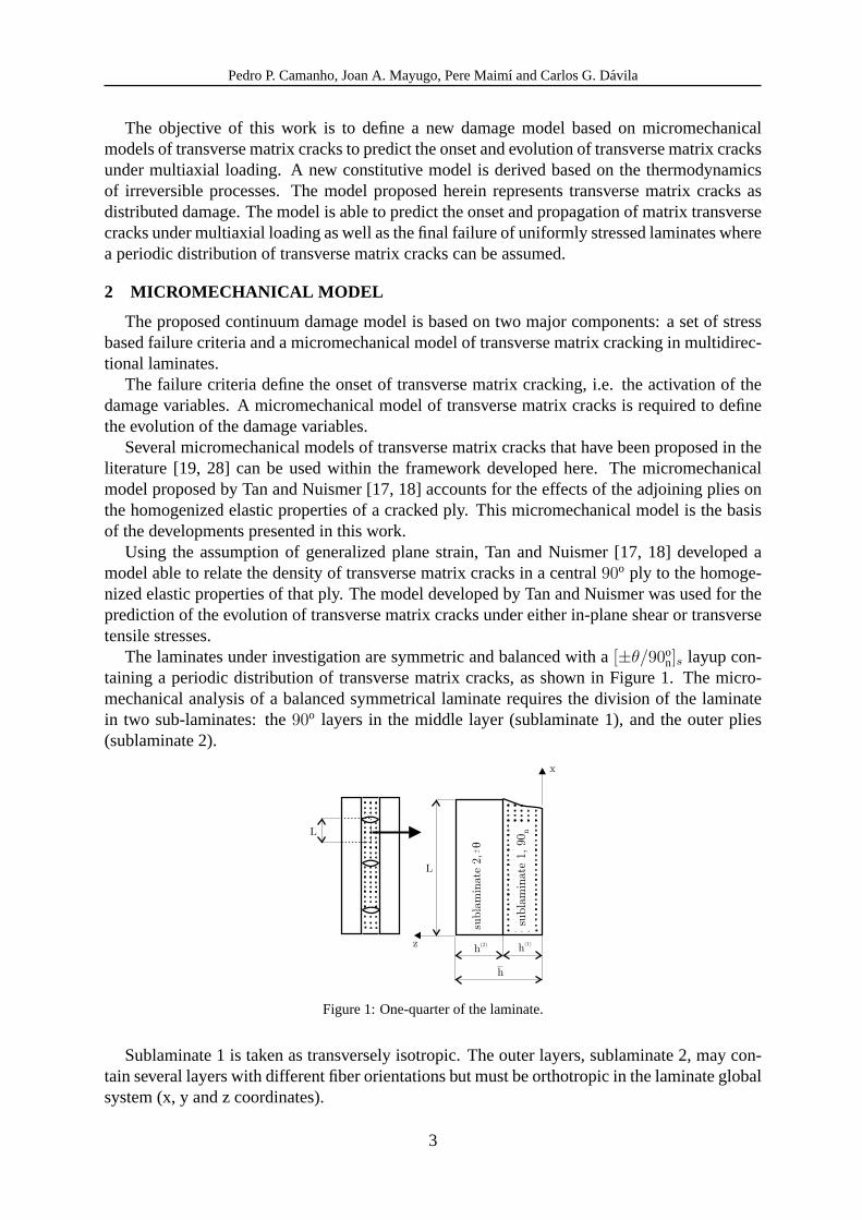
The laminates under investigation are symmetric and balanced with a[±θ/90on]s layup con-
taining a periodic distribution of transverse matrix cracks, as shown in Figure1. The micro-mechanical analysis of a balanced symmetrical laminate requires the division of the laminatein two sub-laminates: the90o layers in the middle layer (sublaminate 1), and the outer plies(sublaminate 2).
subla
min
ate
2,q
h(2) h
(1)
L
z
x
L
subla
min
ate
1, 9
0 n
h
Figure 1:One-quarter of the laminate.
Sublaminate 1 is taken as transversely isotropic. The outer layers, sublaminate 2, may con-tain several layers with different fiber orientations but must be orthotropic in the laminate globalsystem (x, y and z coordinates).
3

Pedro P. Camanho, Joan A. Mayugo, Pere Maimı and Carlos G. Davila
2.1 CONSTITUTIVE TENSOR
The stiffness tensor of the balanced and symmetric laminate shown in Figure1 can be writtenas a function of the density of transverse matrix cracks (1/L) in the sublaminate 1:
A(L) =
A(L)11 A(L)12 0A(L)21 A(L)22 0
0 0 A(L)66
(1)
where the termsAij(L), i, j = 1, 2, 6 are obtained from the Tan and Nuismer model [18].The undamaged stiffness matrixQ of the laminate is obtained from lamination theory using
the undamaged stiffness matrix of sublaminate 1,Q(1), and the stiffness matrix of sublaminate2, Q(2):
Q(1)ij =
1
h(1)
(hQij − h(2)Q
(2)ij
)(2)
with h = h(1) + h(2).Assuming that the degradation due to the transverse matrix cracks only occur in sublaminate
1, the damaged stiffness tensor of laminate 1 is given as:
A(1)ij (L) =
1
h(1)
(hAij(L)− h(2)Q
(2)ij
)(3)
whereA(1)ij (L) (i, j = 1, 2, 6) are the scalar components of the stiffness tensor of sublaminate 1.
These components are a function of the distance between transverse matrix cracks (L, definedin Figure1).
Having definedA(1)ij (L), it is possible to calculate the effective transverse modulus, Poisson
ratio, and shear modulus of the 90◦ ply:
E(1)2 (L) = E(1)
x (L) = A(1)11 (L)−
[A
(1)12 (L)
]2
A(1)22 (L)
(4)
υ(1)21 (L) = υ(1)
xy (L) =A
(1)12 (L)
A(1)22 (L)
(5)
G(1)12 (L) = G(1)
xy (L) = A(1)66 (L) (6)
The quotientυ21
E2is not a function of damage. This observation is in agreement with several
other models, such as the ones proposed by Laws et al. [23, 24], and Nguyen [25].The plane stress compliance tensor of the damaged sublaminate 1,H(1), only contains two
components that depend on the density of transverse matrix cracks:H(1)22 (L) andH
(1)66 (L). The
tensorH(1), is established as a function of the density of transverse matrix cracks,L, as:
H(1)=
1E1
−υ21
E20
−υ12
E1H
(1)22 (L) 0
0 0 H(1)66 (L)
(7)
4
Pedro P. Camanho, Joan A. Mayugo, Pere Maimı and Carlos G. Davila
with:
H(1)22 (L) =
1
E(1)2 (L)
=A
(1)22 (L)
A(1)11 (L)A
(1)22 (L)−
[A
(1)12 (L)
]2 (8)
H(1)66 (L) =
1
G(1)12 (L)
=1
A(1)66 (L)
(9)
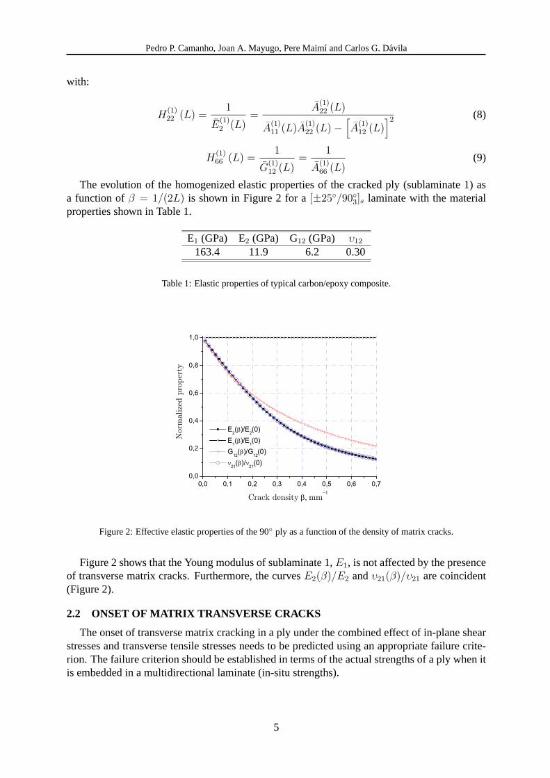
The evolution of the homogenized elastic properties of the cracked ply (sublaminate 1) asa function ofβ = 1/(2L) is shown in Figure2 for a [±25◦/90◦3]s laminate with the materialproperties shown in Table1.
E1 (GPa) E2 (GPa) G12 (GPa) υ12
163.4 11.9 6.2 0.30
Table 1:Elastic properties of typical carbon/epoxy composite.
Figure 2:Effective elastic properties of the 90◦ ply as a function of the density of matrix cracks.
Figure2 shows that the Young modulus of sublaminate 1,E1, is not affected by the presenceof transverse matrix cracks. Furthermore, the curvesE2(β)/E2 andυ21(β)/υ21 are coincident(Figure2).
2.2 ONSET OF MATRIX TRANSVERSE CRACKS
The onset of transverse matrix cracking in a ply under the combined effect of in-plane shearstresses and transverse tensile stresses needs to be predicted using an appropriate failure crite-rion. The failure criterion should be established in terms of the actual strengths of a ply when itis embedded in a multidirectional laminate (in-situ strengths).
5
Pedro P. Camanho, Joan A. Mayugo, Pere Maimı and Carlos G. Davila
2.2.1 In-situ strengths
A methodology to predict the onset of matrix transverse cracking must be able to predictthe in-situ strengths of a ply. Both the transverse tensile and in-plane shear strengths of a plyembedded in a multidirectional laminate are higher than the corresponding values measured inunidirectional laminates [29].
The thick models described in [30] are used. The tensile transverse in-situ strengths ofsublaminate (1) is [30]:
For a thin embedded ply:YT =
√8GIc
πtΛo22
(10)
For a thick ply:YT = 1.12√
2Y udT (11)
whereY udT is the tensile transverse strength measured in a unidirectional test specimen,t is the
thickness of sublaminate 1,GIc is the mode I intralaminar fracture toughness andΛ◦22 is definedas:
Λ◦22 = 2
(1
E2
− υ221
E1
)(12)
The in-situ shear strengths are obtained as [29]:
SL =
√(1 + χφG2
12)1/2 − 1
3χG12
(13)
whereχ is the shear response factor defined in [29], and the parameterφ is calculated accordingto the configuration of the ply:
For a thick ply: φ =12
(Sud
L
)2
G12
+ 18χ(Sud
L
)4
For a thin ply: φ =48GIIc
πt(14)
whereSudL is the shear strength measured using an unidirectional test specimen andGIIc is the
mode II fracture toughness.
2.2.2 Failure criterion for the prediction of transverse cracking under multiaxial loading
In general, a ply represented by sublaminate 1 in Figure1 is subjected to transverse tensilestresses and in-plane shear stresses. Under pure in-plane shear or pure transverse tension, theonset of transverse matrix cracking is predicted by comparing the components of the stresstensor with the respective in-situ strengths (defined in the previous section).
Under multiaxial loading, it is necessary to use a failure criterion to predict the onset ofmatrix cracking. The LaRC04 [4, 5] failure criteria are a function of the components of thestress tensor and in-situ strengths. For transverse tension, the criterion used is:
(1− g)σ22
YT+ g(
σ22
YT)2 + (
σ12
SL)2 − 1 ≤ 0 with σ22 ≥ 0 (15)
6
Pedro P. Camanho, Joan A. Mayugo, Pere Maimı and Carlos G. Davila
whereg = GIcGIIc
. GIIc is the mode II component of the fracture toughness associated with matrixtransverse cracking.
Under moderate values of transverse compression, the cracks propagate along the laminatethickness direction, and the LaRC04 failure criterion is:
1
SL
⟨|σ12|+ ηLσ22
⟩− 1 ≤ 0 with σ22 < 0 (16)
whereηL is the coefficient of longitudinal influence defined in [4, 5].
2.3 Evolution of matrix transverse cracks under multiaxial loading
2.3.1 Transverse tension
Tan and Nuismer [18] obtained a closed-form expression that defines the evolution of trans-verse matrix cracks under uniaxial stress states (either transverse tension or in-plane shear).
To predict failure under multiaxial loading, i.e. when the lamina is simultaneously undertensile and in-plane shear strains,εxx andγxy respectively, it is necessary to derive a relationbetween the density of transverse matrix cracks and the applied multiaxial strain state. It isassumed that the relation between the tensile and shear strains is constant throughout the loadinghistory:
κ =γxy
εxx
with εxx > 0 (17)
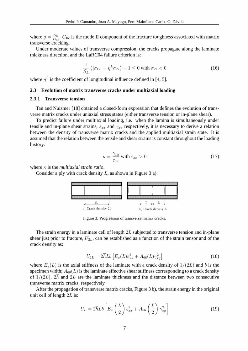
whereκ is themultiaxial strain ratio.Consider a ply with crack densityL, as shown in Figure3 a).
2L
a) Crack density 2L
L
b) Crack density L
L
Figure 3:Progression of transverse matrix cracks.
The strain energy in a laminate cell of length2L subjected to transverse tension and in-planeshear just prior to fracture,U2L, can be established as a function of the strain tensor and of thecrack density as:
U2L = 2hLb[Ex(L)ε2
xx + A66(L)γ2xy
](18)
whereEx(L) is the axial stiffness of the laminate with a crack density of1/(2L) andb is thespecimen width;A66(L) is the laminate effective shear stiffness corresponding to a crack densityof 1/(2L), 2h and 2L are the laminate thickness and the distance between two consecutivetransverse matrix cracks, respectively.
After the propagation of transverse matrix cracks, Figure3b), the strain energy in the originalunit cell of length2L is:
UL = 2hLb
[Ex
(L
2
)ε2
xx + A66
(L
2
)γ2
xy
](19)
7
Pedro P. Camanho, Joan A. Mayugo, Pere Maimı and Carlos G. Davila
whereEx(L/2) and A66(L/2) are respectively the axial stiffness and the laminate effectiveshear stiffness corresponding to a crack density defined byL.
The energy required to generate a new matrix crack in a ply equals the loss of strain energyof the laminate [18]. Therefore, the difference between equation (18) and equation (19) is equalto the energy released by the sublaminate 1:
∆U = U2L − UL =
= 2hLb
{[Ex(L)− Ex
(L
2
)]ε2
xx +
[A66(L)− A66
(L
2
)]γ2
xy
}(20)
∆U = 2h(1)bGc = 2h(1)bGI + 2h(1)bGII (21)
whereGc is the mixed-mode fracture toughness of sublaminate 1 under tensile (mode I) andshear (mode II) loading. From (20) and (21):
[Ex(L)− Ex
(L
2
)]ε2
xx +
[A66(L)− A66
(L
2
)]γ2
xy =h(1)Gc
hL(22)
Using the definition ofκ given in (17), equation (22) can be re-written as a function of thestrains:
{(Ex(L)− Ex
(L
2
))+ κ2
[A66(L)− A66
(L
2
)]}ε2
xx =h(1)Gc
hL(23)
or:
{1
κ2
[Ex(L)− Ex
(L
2
)]+
[A66(L)− A66
(L
2
)]}γ2
xy =h(1)Gc
hL(24)
The relations between the normal and shear strains and the crack density are obtained as:
εxx =
√h(1)Gc
hL
1[Ex(L)− Ex
(L2
)]+ κ2
[A66(L)− A66
(L2
)] (25)
γxy =
√h(1)Gc
hL
κ2
[Ex(L)− Ex
(L2
)]+ κ2
[A66(L)− A66
(L2
)] = κεxx (26)
Equations (25) and (26), are established as a function of the mixed-mode fracture toughnessGc that needs to be defined.
The mixed-mode fracture toughness is defined in terms of the mode I and mode II compo-nents as:
Gc = GI + GII (27)
From (27) and (22):h(1)GI
hL=
[Ex(L)− Ex
(L
2
)]ε2
xx (28)
h(1)GII
hL=
[A66(L)− A66
(L
2
)]γ2
xy (29)
8
Pedro P. Camanho, Joan A. Mayugo, Pere Maimı and Carlos G. Davila
Dividing equations (28) and (29) by (23) and (24), respectively:
AI =GI
Gc
=
[Ex(L)− Ex
(L2
)][Ex(L)− Ex
(L2
)]+ κ2
[A66(L)− A66
(L2
)] (30)
AII =GII
Gc
=κ2
[A66(L)− A66
(L2
)][Ex(L)− Ex
(L2
)]+ κ2
[A66(L)− A66
(L2
)] (31)
AI andAII are the ratios between the mode I and mode II components of the energy releaserate and the mixed-mode fracture toughness.
The criterion proposed by Hahn [31] for the prediction of transverse matrix cracking undertransverse tensile and in-plane shear loads is used:
(1− g)
√GIIc
GIc+ g
GI
GIc+
GII
GIIc= 1 (32)
Substituting equations (30) and (31) into (32) gives:
(1− g)
√AIGc
GIc+ g
AIGc
GIc+
(1− AI) Gc
GIIc= 1 (33)
The positive real solution of (33) is:
Gc = GIIc +AI
2
(GIc −GIIc)2
GIc
(1−
√1 +
4
AI
GIcGIIc
(GIc −GIIc)2
)(34)
whereAI depends on the density of transverse matrix cracks,β, and on the multiaxial strainratio,κ (equation (30)).
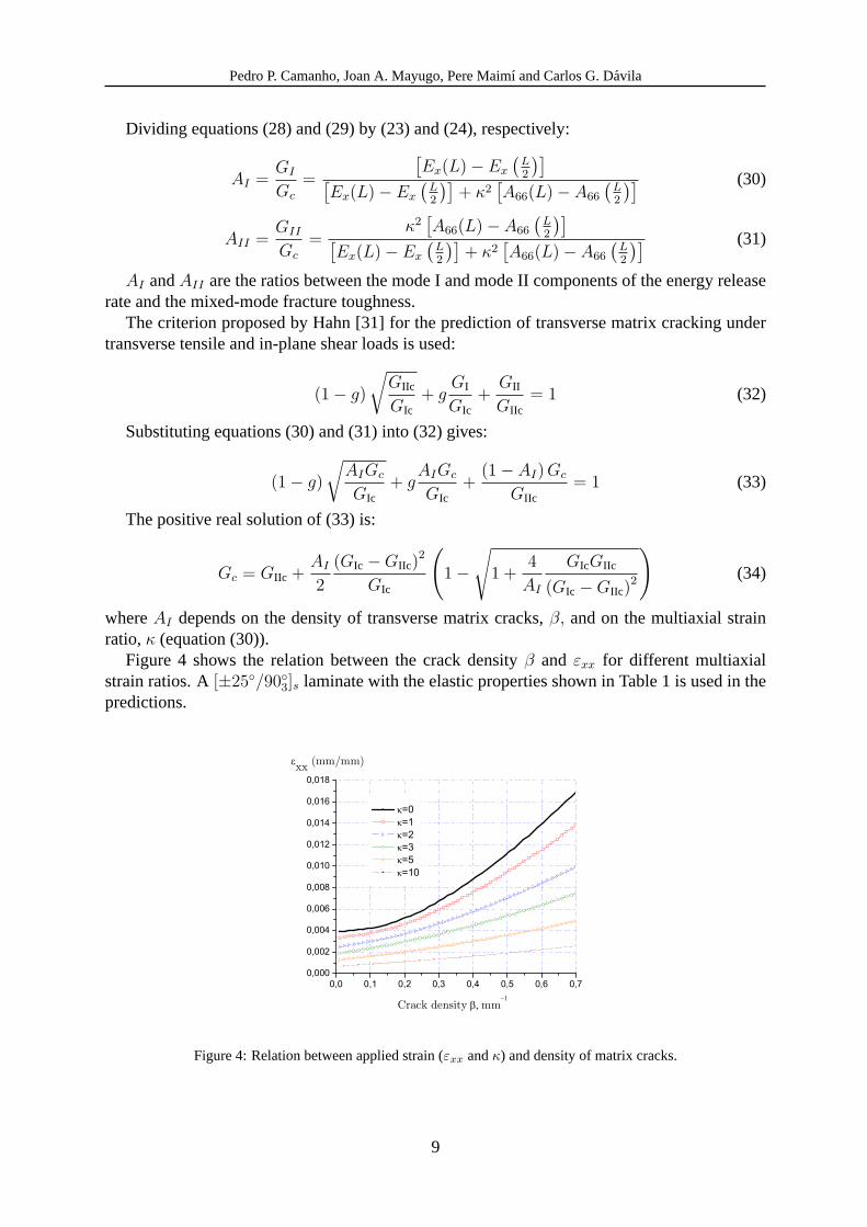
Figure 4 shows the relation between the crack densityβ and εxx for different multiaxialstrain ratios. A[±25◦/90◦3]s laminate with the elastic properties shown in Table1 is used in thepredictions.
Figure 4:Relation between applied strain (εxx andκ) and density of matrix cracks.
9
Pedro P. Camanho, Joan A. Mayugo, Pere Maimı and Carlos G. Davila
The effects of multiaxial strain states on the crack density are clearly shown in Figure4.It can be observed in Figure4 that the density of transverse matrix cracks increases with themultiaxial strain ratio for a fixed value ofεxx.
2.3.2 Transverse compression
Transverse matrix cracks created by a combination of transverse compression and in-planeshear close under the effect of the compressive transverse stress. When a crack closes, its facescan transmit normal tractions but shear tractions may cause slippage between the crack faces.Therefore, it can be assumed that transverse matrix cracks only affect the shear stiffness of alaminate.
Following the procedure described in the previous section, the energy released by the sub-laminate 1 is:
∆U = 2hLbγ2xy
[A66(L)− A66
(L
2
)]= 2h(1)bGIIc (35)
The relation between the shear strain and the crack density is obtained as:
γxy =
√h(1)GIIc
hL[A66(L)− A66
(L2
)] (36)
3 MICROMECHANICS-BASED DAMAGE MODEL
3.1 Constitutive model
A damage model able to represent the onset and accumulation of a periodic distribution oftransverse matrix cracks should yield a compliance tensor similar to the one obtained fromthe micromechanical model, equation (7). An appropriate damage model can be developed bydefining the Gibbs free energy per unit volume,ΨG, as:
ΨG =1
2
[σ2
11
E1
+σ2
22
(1− d2) E2
+σ2
12
(1− d6) G12
−(
υ21
E2
+υ12
E1
)σ11σ22
]+
+ (α11σ11 + α22σ22) ∆T + (β11σ11 + β22σ22)∆M (37)
whereE1, E2, υ12, υ21 andG12 are the in-plane elastic orthotropic properties of a unidirectionallamina. The subscript 1 denotes the longitudinal (fiber) direction and 2 denotes the transverse(matrix) direction. d2 andd6 are damage variables associated with transverse matrix crack-ing. α11 andα22 are the coefficients of thermal expansion in the longitudinal and transversedirections, respectively.β11 andβ22 are the coefficients of hygroscopic expansion in the lon-gitudinal and transverse directions, respectively.∆T and∆M are respectively the changes intemperature and moisture content from the stress-free state.
The proposed model distinguishes between active(d2+) and passive damage(d2−) variables,corresponding to the opening or closure of transverse matrix cracks under load reversal respec-tively. To account for the active damage under either opening or closure, the following equationis proposed:
d2 = d2+〈σ22〉|σ22| + d2−
〈−σ22〉|σ22| (38)
10
Pedro P. Camanho, Joan A. Mayugo, Pere Maimı and Carlos G. Davila
where the McCauley operator〈x〉 is defined as〈x〉 := 12(x + |x|).
The damage variablesd2 andd6 can be related to the density of transverse matrix cracksusing the micromechanical model previously described.
The constitutive model is obtained as:
ε =∂ΨG
∂σ= H : σ+∆Tα + ∆Mβ (39)
where the compliance tensorH is:
H =∂2ΨG
∂σ2=
1E1
−υ21
E20
−υ12
E1
1(1−d2)E2
0
0 0 1(1−d6)G12
(40)
The compliance tensor is established in terms of the damage variables and is similar to thecompliance tensor derived in the micromechanical model.
Using (7) and (40) the damage variablesd2 andd6 can be expressed in terms of the crackdensityβ as:
d2+ = 1− 1
E2H22 (β)(41)
d6 = 1− 1
G12H66 (β)(42)
The functionsH22 (β) andH66 (β) are obtained from equations (8) and (9) with β = 1/(2L).The condition of positive energy dissipation is established as a function of the thermody-
namic forces,Y, and as a function of the time derivative of the damage variables,d, and it isgiven by:
Ξ = Y · d =∂ΨG
∂d· d ≥ 0
Ξ =σ2
22
2 (1− d2+)2 E2
d2+ +σ2
12
2 (1− d6)2 G12
d6≥0 (43)
whereΞ is the rate of energy dissipation per unit volume.The condition of positive dissipation, when interpreted from a micromechanical point of
view, establishes that the density of transverse matrix cracks can only increase or remain con-stant.
3.1.1 Damage activation functions
Transverse matrix cracks are predicted using two scalar functions,Fk (k = 2+, 2−), estab-lished in terms of the effective stress tensorσt, and of the damage threshold value,rt:
Fk := φk
(σt
)− rt ≤ 0 (44)
wheret is the current time. The initial threshold value,r◦, is equal to 1, and the followingcondition must be satisfied in order to fulfill the Second Principle of Thermodynamics:
r ≥ 0 (45)
11
Pedro P. Camanho, Joan A. Mayugo, Pere Maimı and Carlos G. Davila
Damage onset occurs when any of the functionsφk (σt) reaches the initial damage thresholdvalue of 1. The functionsφk (σt) used to predict transverse matrix cracking are based on theLaRC04 failure criteria previously proposed by the authors [4, 5]. The damage activation func-tions are used to predict the onset of transverse matrix cracks lying in ply thickness direction,as shown in Figure1.
Transverse matrix cracks lying in the direction of the ply thickness occur under transversetension(σ22 ≥ 0), or under moderate values of transverse compression and in-plane shear(σ22 < 0).
For high values of transverse compression, the matrix fractures lie along a plane that isinclined at an angleα to the direction of the ply thickness. Inclined fracture planes causedby transverse compression induce delamination between the plies. This damage mechanism isusually catastrophic in uniformly stressed composites where local redistribution to more lightlyloaded regions of the structure cannot occur [6]. Therefore, laminate failure can be assumed tooccur when matrix cracking under high values of transverse compression is predicted.
The damage activation function used to predict matrix cracking under transverse tension(σt
22 ≥ 0) and in-plane shear is defined as:
F2+ := φ2+
(σt
)− rt ≤ 0 (46)
with:
φ2+
(σt
)=
√(1− g)
σt22
YT+ g
(σt
22
YT
)2
+
(σt
12
SL
)2
(47)
The damage activation function used to predict matrix cracking withα = 0◦ under moderatevalues of transverse compression (σt
22 < 0) and in-plane shear is defined as:
F2- := φ2-
(σt
)− rt ≤ 0 (48)
with:
φ2-
(σt
)=
α=0o
1
SL
⟨∣∣σt12
∣∣ + ηLσt22
⟩(49)
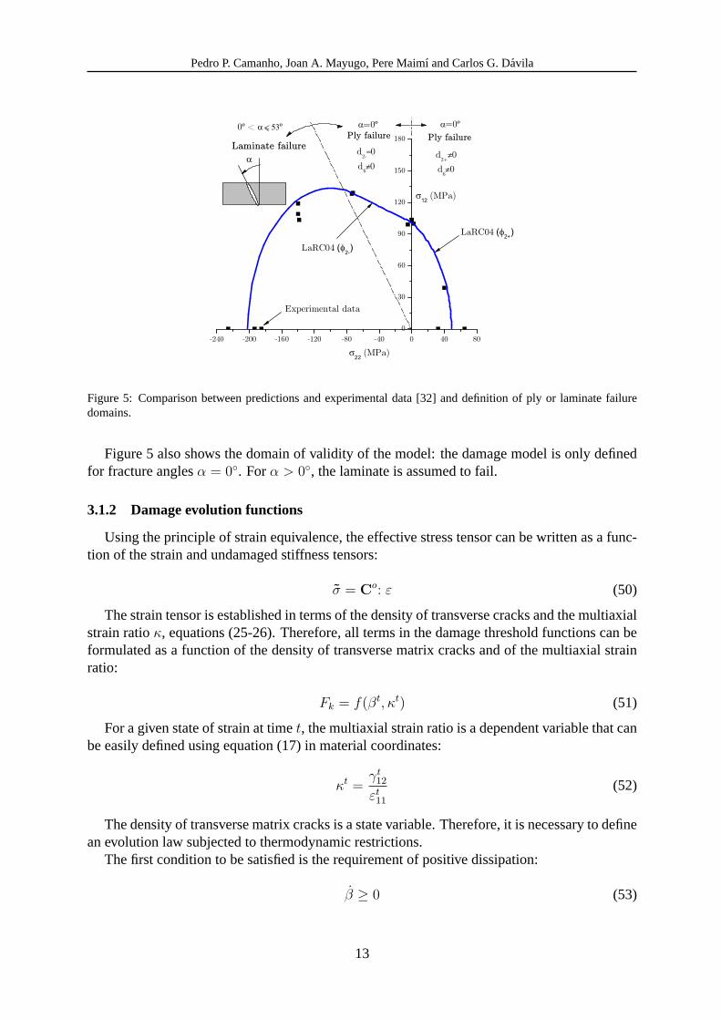
The equations proposed can predict accurately transverse matrix transverse cracking. Thefailure envelope, or initial elastic limit, predicted using equations (46) and (48), and the corre-sponding experimental data are shown in Figure5.
12
Pedro P. Camanho, Joan A. Mayugo, Pere Maimı and Carlos G. Davila
Figure 5: Comparison between predictions and experimental data [32] and definition of ply or laminate failuredomains.
Figure5 also shows the domain of validity of the model: the damage model is only definedfor fracture anglesα = 0◦. Forα > 0◦, the laminate is assumed to fail.
3.1.2 Damage evolution functions
Using the principle of strain equivalence, the effective stress tensor can be written as a func-tion of the strain and undamaged stiffness tensors:
σ = Co: ε (50)
The strain tensor is established in terms of the density of transverse cracks and the multiaxialstrain ratioκ, equations (25-26). Therefore, all terms in the damage threshold functions can beformulated as a function of the density of transverse matrix cracks and of the multiaxial strainratio:
Fk = f(βt, κt) (51)
For a given state of strain at timet, the multiaxial strain ratio is a dependent variable that canbe easily defined using equation (17) in material coordinates:
κt =γt
12
εt11
(52)
The density of transverse matrix cracks is a state variable. Therefore, it is necessary to definean evolution law subjected to thermodynamic restrictions.
The first condition to be satisfied is the requirement of positive dissipation:
β ≥ 0 (53)
13
Pedro P. Camanho, Joan A. Mayugo, Pere Maimı and Carlos G. Davila
Furthermore, it is necessary to define the conditions for the evolution of the elastic domain:
Fk(σt, βt) ≤ 0 (54)
βFk(σt, βt) = 0 (55)
Equations (53)-(55) are the Kuhn-Tucker conditions which ensure a consistent evolution ofdamage during loading and load reversals.
The evolution laws of the state variables are defined as:
·σ =
∂σ
∂ε: ε =
∂σ
∂ε:
(∂ε
∂ββ +
∂ε
∂κκ
)= Co :
(∂ε
∂ββ +
∂ε
∂κκ
)(56)
r =∂r
∂ββ +
∂r
∂κκ (57)
For a given loading state, the damage consistency condition must be applied to define theevolution of the internal variables. The consistency condition is defined as:
Fk = 0 ⇒ Fk =∂Fk
∂σ:·σ +
∂Fk
∂rr = 0 (58)
From (46) and (48):∂Fk
∂r= −1 (59)
Using (59) in (58):
Fk =∂Fk
∂σ:·σ − r =
∂Fk
∂σ: Co : ε− r = 0 (60)
Using equations (56) and (57) in (60):
Fk =∂Fk
∂σ: Co :
(∂ε
∂ββ +
∂ε
∂κκ
)−
(∂r
∂ββ +
∂r
∂κκ
)= 0 (61)
Taking into account that the micromechanical model proposed assumes a constant loadingratio, κ = 0:
Fk =∂Fk
∂σ:
(Co :
∂ε
∂β− ∂r
∂β
)β = 0 (62)
The density of of transverse matrix cracks,β, is calculated from the integration of equation(62) using a numerical method, such as the return-mapping algorithm.
4 LAMINATE FAILURE
In the presence of stress concentrations the onset of fiber localized failure does not causeimmediate structural collapse. Experimental results [33, 34] show that structural collapse iscaused by the the progression of fiber fracture. Therefore, it is necessary to use a damage modelthat accounts for the stress re-distributions caused by fiber fractures.
The model proposed here assumes that for uniformly stressed laminates the onset of fiberfracture and delamination caused by high compressive transverse stresses triggers structuralcollapse. Therefore, laminate final failure is predicted when fiber failure or matrix crackingwith α 6= 0◦ occurs.
14
Pedro P. Camanho, Joan A. Mayugo, Pere Maimı and Carlos G. Davila
4.1 Fiber failure
The criterion for fiber fracture under longitudinal tension (σ11 ≥ 0) is defined as [4, 5]:
FI1+ :=σ11
XT− 1 ≤ 0 (63)
whereXT is the ply tensile strength in the longitudinal direction.The LaRC03 failure criterion for fiber kinking under longitudinal compression (σ11 < 0) is a
function of the components of the stress tensor in a frame representing the fiber misalignment,σ
(m)ij [4, 5]:
σ(m)11 = σ11 cos2 ϕ + σ22 sin2 ϕ + 2 |σ12| sin ϕ cos ϕ
σ(m)22 = σ11 sin2 ϕ + σ22 cos2 ϕ− 2 |σ12| sin ϕ cos ϕ
σ(m)12 = −σ11 sin ϕ cos ϕ + σ22 sin ϕ cos ϕ + |σ12|
(cos2 ϕ− sin2 ϕ
) (64)
where the fiber misalignment angleϕ is defined as [4]:
ϕ =|σ12|+ (G12 −XC) ϕc
G12 + σ11 − σ22
(65)
ϕc = tan−1
1−√
1− 4(
SLXC
+ ηL)(
SLXC
)
2(
SLXC
+ ηL)
(66)
whereXC is the ply compressive strength in the longitudinal direction.Depending on the sign of the in-plane transverse stressσ
(m)22 , the criteria for fiber kinking
(σ11 < 0) are:
FI1- : =
⟨∣∣∣σ(m)12
∣∣∣ + ηLσ(m)22
SL
⟩− 1 ≤ 0, σ
(m)22 < 0 (67)
or FI1- : = (1− g)σ
(m)12
YT+ g
(σ
(m)12
YT
)2
+
(σ
(m)12
SL
)2
− 1 ≤ 0, σ(m)22 ≥ 0 (68)
4.2 Matrix failure with α 6= 0◦
The failure criteria for matrix cracking under transverse compression (σ22 < 0) and in-planeshear andα 6= 0◦ are defined as [4, 5]:
FI2- :=
(τTe
ST
)2
+
(τLe
SL
)2
− 1 ≤ 0, |σ11| ≤ YC (69)
FI2- :=
(τ
(m)Te
ST
)2
+
(τ
(m)Le
SL
)2
− 1 ≤ 0, |σ11| > YC (70)
where the effective shear stresses in the fracture plane are defined as:
15
Pedro P. Camanho, Joan A. Mayugo, Pere Maimı and Carlos G. Davila
τTe =
⟨∣∣τT∣∣ + ηT σn cos θ
⟩(71)
τLe =
⟨∣∣τL∣∣ + ηLσn sin θ
⟩(72)
whereθ = tan−1(
−|σ12|σ22 sin α
). The components of the stress tensor on the fracture plane are given
by [4, 5]:
σn = σ22 cos2 ατT = −σ22 sin α cos ατL = σ12 cos α
(73)
The termsτmTe andτmL
e are calculated from equations (71)-(73) using the relevant compo-nents of the stress tensor established in a frame representing the fiber misalignment, equation(64). The angleα is determined by maximizing the failure index FI2− (69-70) using a simpleiterative procedure.
The coefficients of transverse and longitudinal influence,ηT andηL, respectively, are [4, 5]:
ηT =−1
tan 2α0
(74)
ηL = −SL cos 2α0
YC cos2 α0
(75)
with α0 ≈ 53◦. YC is the ply compressive strength in the transverse direction.
5 EXAMPLES
The present damage model can be used in combination with classical lamination theoryusing stand-alone codes. Alternatively, the damage model can be implemented as a constitutivesubroutine for the finite element method.
The damage model was implemented using a commercial symbolic computing software. Themodel was verified by calculating the response of several glass-epoxy laminates under uniaxialand multiaxial loads:[±45◦/90◦4]s, [0◦2/90◦4]s, [0◦2/90◦2]s and[0◦2/90◦]s.
In all calculations performed, the ply thickness was taken as 0.144mm, and the temperaturedifference from the stress free condition was -100◦C. The coefficients of thermal expansion inthe longitudinal and transverse directions areα11 = 7.43×10⁻⁶/◦C andα22 = 22.4×10⁻⁶/◦C,respectively. The remaining material properties used are shown in Tables2 and3.
E1 (GPa) E2 (GPa) G12 (GPa) G23 (GPa) υ12 υ23 χ (10−8MPa−3)44.7 12.8 5.8 4.5 0.30 0.42 2.0
Table 2:Elastic properties of glass-epoxy [20]
16
Pedro P. Camanho, Joan A. Mayugo, Pere Maimı and Carlos G. Davila
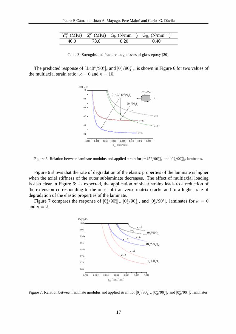
YudT (MPa) Sud
L (MPa) GIc (N/mm−1) GIIc (N/mm−1)40.0 73.0 0.20 0.40
Table 3:Strengths and fracture toughnesses of glass-epoxy [20].
The predicted response of[±40◦/90◦4]s and[0◦2/90◦4]s, is shown in Figure6 for two values ofthe multiaxial strain ratio:κ = 0 andκ = 10.
Figure 6:Relation between laminate modulus and applied strain for[±45◦/90◦4]s and[0◦2/90◦4]s laminates.
Figure6 shows that the rate of degradation of the elastic properties of the laminate is higherwhen the axial stiffness of the outer sublaminate decreases. The effect of multiaxial loadingis also clear in Figure6: as expected, the application of shear strains leads to a reduction ofthe extension corresponding to the onset of transverse matrix cracks and to a higher rate ofdegradation of the elastic properties of the laminate.
Figure7 compares the response of[0◦2/90◦4]s, [0◦2/90◦2]s and [0◦2/90◦]s laminates forκ = 0andκ = 2.
Figure 7:Relation between laminate modulus and applied strain for[0◦2/90◦4]s, [0◦2/90◦2]s and[0◦2/90◦]s laminates.
17
Pedro P. Camanho, Joan A. Mayugo, Pere Maimı and Carlos G. Davila
The in-situ effect is shown in Figure7: for κ = 0, the strain corresponding to the onsetof matrix cracking of the[0◦2/90◦]s laminate is 1.9 and 1.3 times higher than the strains of the[0◦2/90◦4]s and [0◦2/90◦2]s laminates respectively. Furthermore, the strain at the onset of matrixcracking of the[0◦2/90◦]s is 2.7 times higher than the ultimate transverse strain measured in anunidirectional test specimen.
6 CONCLUSIONS
A new, micromechanics-based, continuum damage model able to simulate the onset andpropagation of transverse matrix cracks and final laminate failure is proposed. The model isapplicable to[±θ◦/90◦n]s laminates, under multiaxial loading and uniform stresses or smallstress gradients.
The model uses ply properties and does not require any tests performed at the laminatelevel to identify damage onset and evolution functions. The onset of damage is predicted usingfailure criteria and damage evolution laws are established from the micromechanical analysisof cracked plies.
The onset and accumulation of transverse matrix cracks are represented as a distributed dam-age mechanism. The onset of localization, which is triggered by either fiber fracture or matrixcracking withα 6= 0, is assumed to cause a structural collapse.
The predictions show that the rate of degradation of the elastic properties increases whenthe stiffness of the outer sublaminate decreases. Decreasing the thickness of the90◦ plies alsoincreases the degradation rate.
Acknowledgements
The financial support of the Portuguese Foundation for Science and Technology (FCT) underthe project PDCTE/EME/50354/2003 is acknowledged by the second author. The present workhas been partially funded by the Spanish Government under research project MAT2003-09768-C03-001.
REFERENCES
[1] MIL-HDBK-17-3F, Military Handbook, Polymer Matrix Composites. U.S. Department ofDefense, 2002.
[2] M.J. Hinton, A.S. Kaddour, and P. D. Soden, A comparison of the predictive capabilitiesof current failure theories for composite laminates, judged against experimental evidence.Composites Science and Technology, 62, 1725-1797, 2002.
[3] P.D. Soden, A.S. Kaddour, and M.J. Hinton, Recommendations for designers and re-searchers resulting from the world-wide failure exercise.Composites Science and Tech-nology, 64, 589-604, 2004.
[4] C.G. Davila and P.P. Camanho, Failure criteria for FRP laminates in plane stress,NASA/TM-2003-212663, National Aeronautics and Space Administration, 2003.
[5] S.T. Pinho, C.G. Davila, P.P. Camanho, L. Iannucci and P. Robinson, Failure models andcriteria for FRP under in-plane shear or three-dimensional stress states including shearnon-linearity.NASA/TM-2005-213530, National Aeronautics and Space Administration,2005.
18
Pedro P. Camanho, Joan A. Mayugo, Pere Maimı and Carlos G. Davila
[6] A. Puck and H. Schurmann, Failure analysis of FRP laminates by means of physicallybased phenomenological models,Composites Science and Technology, 58, 1045-1067,1998.
[7] K.S. Liu, and S.W. Tsai, A progressive quadratic failure criterion for a laminate,Compos-ites Science and Technology, 58, 1023-1032, 1998.
[8] Z.P. Bazant, Size effect.International Journal of Solids and Structures, 37, 69-80, 2000.
[9] P. Ladeveze, On a damage mechanics approach. Mechanics and Mechanisms of damagein composites and multi-materials. D. Batiste ed., 119-141, London, 1991.
[10] K.V. Williams, R. Vaziri and A. Poursartip. A physically based continuum damage me-chanics model for thin laminated composite structures,International Journal of Solidsand Structures, 40, 2267-2300, 2003.
[11] J. Varna, R. Joffe, N.V. Akshantala and R. Talreja, Damage in composite laminates withoff-axis plies,Composites Science and Technology, 59, 2139-2147, 1999.
[12] D.H. Allen, C.E. Harris and S.E. Groves, A thermomechanical constitutive theory for elas-tic composites with distributed damage- I. theoretical development,International Journalof Solids and Structures, 23, 1301-1318, 1987.
[13] D.H. Allen, C.E. Harris and S.E. Groves, A thermomechanical constitutive theory forelastic composites with distributed damage- II. application to matrix cracking in laminatedcomposites,International Journal of Solids and Structures, 23, 1319-1338, 1987.
[14] C.T. Herakovich, Mechanics of Fibrous Composites. Wiley, 1997.
[15] Z.P. Bazant and B.H. Oh, Crack band theory for fracture of concrete.Materiaux et Con-structions, 16, 155-177, 1983.
[16] M. Jirasek, Modeling of localized damage and fracture in quasibrittle materials. LectureNotes in Physics 568,17-29,P.A. Vermeer et al. ed., 2001.
[17] R.J. Nuismer and S.C. Tan, Constitutive relations of a cracked composite lamina,Journalof Composite Materials, 22, 306-321, 1988.
[18] S.C. Tan and R.J. Nuismer, A theory for progressive matrix cracking in composite lami-nates,Journal of Composite Materials, 23, 1029-1047, 1989.
[19] L.A. Berglund, J. Varna and J. Yuan, Effect of intralaminar toughness on the transversecracking strain in cross-ply laminates.Advanced Composite Materials, 1, 225-234, 1991.
[20] R. Joffe, A. Krasnikovs and J. Varna, COD-based simulation of transverse cracking andstiffness reduction in (S/90n)s laminates,Composites Science and Technology, 61, 637-656, 2001.
[21] R. Joffe and J. Varna, Analytical modeling of stiffness reduction in symmetric and bal-anced laminates due to cracks in 90 layers.Composites Science and Technology, 59, 1641-1652, 1999.
19
Pedro P. Camanho, Joan A. Mayugo, Pere Maimı and Carlos G. Davila
[22] J. Varna, R. Joffe and R. Talreja, A synergistic damage-mechanics analysis of transversecracking in (±θ/904)s laminates.Composites Science and Technology, 61, 657-665, 2001.
[23] G.J. Dvorak, N. Laws and M. Hejazi, Analysis of progressive matrix cracking in compositelaminates I. thermoelastic properties of a ply with cracks,Journal of Composite Materials,19, 216-234, 1985.
[24] N. Laws, G.J. Dvorak and M. Hejazi, Stiffness changes in unidirectional compositescaused by crack systems,Mechanics of Materials, 2, 123-137, 1983.
[25] B.N. Nguyen, A three-dimensional modeling of transverse matrix cracking in laminatedcomposites,Key Engineering Materials, 127, 1117-1126, 1997.
[26] G.A. Schoeppner and N.J. Pagano, 3-D thermoelastic moduli and saturation crack densityfor cross-ply laminates with transverse cracks,International Journal of Damage Mechan-ics, 8, 1-37, 1999.
[27] Z. Hashin, Analysis of cracked laminates: a variational approach,Mechanics of Materials,4, 121-136, 1985.
[28] L.N. McCartney, G.A. Schoeppner and W. Becker, Comparison of models for transverseply cracks in composite laminates,Composites Science and Technology, 60, 2347-2359,20009.
[29] P.P. Camanho, C.G. Davila, S.T. Pinho, L. Iannucci and P. Robinson, Prediction of in-situ strengths and transverse matrix cracking in composites under transverse tension andin-plane shear,Composites-Part A, 37, 165-176, 2006.
[30] G.J. Dvorak and N. Laws, Analysis of first ply failure in composite laminates,EngineeringFracture Mechanics, 25, 763-770, 1986.
[31] H.T. Hahn, A mixed-mode fracture criterion for composite materials,Composites Tech-nology Review, 5, 26-29, 1983.
[32] S.R. Swanson, A micro-mechanical model for in-situ compression strength of fiber com-posite laminates,Transactions of the American Society of Mechanical Engineers, SeriesH, Journal of Engineering Materials and Technology, 114, 8-12, 1992.
[33] P.P. Camanho, S. Bowron and F.L. Matthews, Failure mechanisms in bolted CFRP,Journalof Reinforced Plastics and Composites, 17, 205-233, 1998.
[34] P.P. Camanho, Application of numerical methods to the strength prediction of mechani-cally fastened joints in composite laminates.PhD Thesis, Centre for Composite Materials,Department of Aeronautics, Imperial College London, U.K., 1999.
20