Embed Size (px)
Citation preview
Powertrain Automotive Technology
Developments at Lotus
Volvo rolls out its first V8
Lotus Engineering Change the Rules
The official industry newsletter of Lotus Engineering
Issue 4September / October 2004
2Lotus Engineering Change the rules
2
7
Managing Innovation
Product and process innovation is the lifeblood of any organisation and this concept is particularly important to Group Lotus.
Lotus invests significant resources in research to produce innovative yet practical solutions. Novel design patents and know-how are generated during the engineering programmes for Lotus cars products and in research programmes aimed at developing new technologies for the engineering market place. It was at Lotus Engineering for example that Active Suspension and Active Noise Control were developed.
To continue its growth as a consultancy business, Lotus Engineering has to be one step ahead, continually offering its automotive OEM and Tier 1 customers the ability to develop vehicles that are not only ground breaking in their design and functionality, but that also meet:-
• Stringent future emissions and safety legislation
• Consumer demands for minimal product lifecycle cost of operation (vehicle sales price and fuel economy)
• The need for product differentiation; features that are appealing to the consumer and generate incremental sales.
• The need for faster-to-market engineering programmes
In order to fulfil such criteria it is vital that Lotus Engineering refreshes its capabilities regularly through investment in research and development. Not all projects however make it to development stage. Lotus’ steering committee approves projects through analysis of market benefits and strategic fit to the business. Application of this disciplined approach ensures that only the most value-added projects are undertaken. Concepts currently being developed include Camless Active Valve Train, Engine Downsizing, Versatile Vehicle Architecture and Composite Car.
In this ‘research and development’ issue of proActive you will see some of the powertrain projects and products resulting from collaborative partnerships which began at the research stage and are now bringing distinct advantage to the industry.
Oliver Shearman
Head of Research & Technologies
Contents
Welcome
3
9
news
PSA sets ‘modest’ target for stop-start fitment of 50,000 units by 2006-8
Toyota launches second of 5 planned ‘innovative international multi purposeVehicles’ in Indonesia - 2nd Sept
Chrysler president calls for more co-op from suppliers - 2nd Sept
Volvo rolls out its first V8 - 7 Sept
features
5
3
73 Automotive industry R&D and the unseen billions
Powertrain Automotive Technology Developements at Lotus
Reducing Product Development Time Using Design Based Suspension Analysis
Controlled Vehicle Dynamics (CVD), - Is this next generation vehicle stability?
Sept/Oct 2004
9
13
16
3Lotus Engineering Change the rules
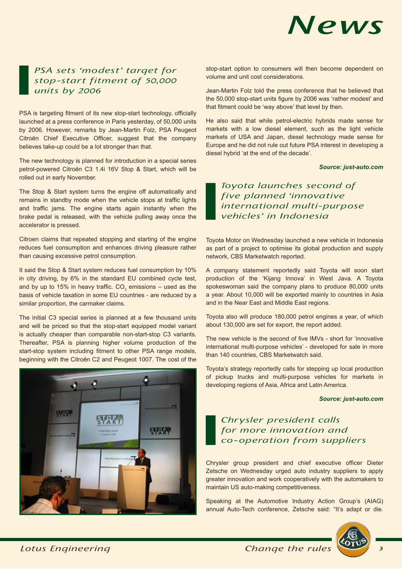
PSA is targeting fitment of its new stop-start technology, officially launched at a press conference in Paris yesterday, of 50,000 units by 2006. However, remarks by Jean-Martin Folz, PSA Peugeot Citroën Chief Executive Officer, suggest that the company believes take-up could be a lot stronger than that.
The new technology is planned for introduction in a special series petrol-powered Citroën C3 1.4i 16V Stop & Start, which will be rolled out in early November.
The Stop & Start system turns the engine off automatically and remains in standby mode when the vehicle stops at traffic lights and traffic jams. The engine starts again instantly when the brake pedal is released, with the vehicle pulling away once the accelerator is pressed.
Citroen claims that repeated stopping and starting of the engine reduces fuel consumption and enhances driving pleasure rather than causing excessive petrol consumption.
It said the Stop & Start system reduces fuel consumption by 10% in city driving, by 6% in the standard EU combined cycle test, and by up to 15% in heavy traffic. CO2 emissions – used as the basis of vehicle taxation in some EU countries - are reduced by a similar proportion, the carmaker claims.
The initial C3 special series is planned at a few thousand units and will be priced so that the stop-start equipped model variant is actually cheaper than comparable non-start-stop C3 variants. Thereafter, PSA is planning higher volume production of the start-stop system including fitment to other PSA range models, beginning with the Citroën C2 and Peugeot 1007. The cost of the
Toyota Motor on Wednesday launched a new vehicle in Indonesia as part of a project to optimise its global production and supply network, CBS Marketwatch reported.
A company statement reportedly said Toyota will soon start production of the ‘Kijang Innova’ in West Java. A Toyota spokeswoman said the company plans to produce 80,000 units a year. About 10,000 will be exported mainly to countries in Asia and in the Near East and Middle East regions.
Toyota also will produce 180,000 petrol engines a year, of which about 130,000 are set for export, the report added.
The new vehicle is the second of five IMVs - short for ‘innovative international multi-purpose vehicles’ - developed for sale in more than 140 countries, CBS Marketwatch said.
Toyota’s strategy reportedly calls for stepping up local production of pickup trucks and multi-purpose vehicles for markets in developing regions of Asia, Africa and Latin America.
Source: just-auto.com
PSA sets ‘modest’ target for stop-start fitment of 50,000 units by 2006
stop-start option to consumers will then become dependent on volume and unit cost considerations.
Jean-Martin Folz told the press conference that he believed that the 50,000 stop-start units figure by 2006 was ‘rather modest’ and that fitment could be ‘way above’ that level by then.
He also said that while petrol-electric hybrids made sense for markets with a low diesel element, such as the light vehicle markets of USA and Japan, diesel technology made sense for Europe and he did not rule out future PSA interest in developing a diesel hybrid ‘at the end of the decade’.
Source: just-auto.com
News
Toyota launches second of five planned ‘innovative international multi-purpose vehicles’ in Indonesia
Chrysler president calls for more innovation and co-operation from suppliers
Chrysler group president and chief executive officer Dieter Zetsche on Wednesday urged auto industry suppliers to apply greater innovation and work cooperatively with the automakers to maintain US auto-making competitiveness.
Speaking at the Automotive Industry Action Group’s (AIAG) annual Auto-Tech conference, Zetsche said: “It’s adapt or die.
4Lotus Engineering Change the rules
Newsto the company’s Toledo North Jeep assembly plant.
In an arrangement similar to the rolling-chassis concept pioneered by Dana Corp. in 1998 for Chrysler’s short-lived Dodge Dakota pick-up building project in Brazil, where the supplier controlled assembly of the rolling undercarriage, integrating parts from nearby suppliers,
Chrysler’s US plant suppliers will own and operate the body and paint shops plus chassis assembly operations within the Toledo facility.
This is the first time suppliers will operate as an integral part of an American vehicle assembly plant but, ironically, and despite its demonstrated expertise in Brazil, US-based Dana lost out to South Korea’s Hyundai Mobis in the bidding to supply the rolling chassis for Jeeps built at Toledo, according to a recent WardsAuto.com report.
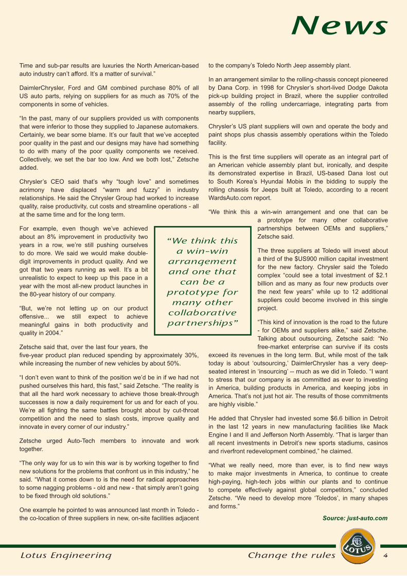
“We think this a win-win arrangement and one that can be a prototype for many other collaborative partnerships between OEMs and suppliers,” Zetsche said.
The three suppliers at Toledo will invest about a third of the $US900 million capital investment for the new factory. Chrysler said the Toledo complex “could see a total investment of $2.1 billion and as many as four new products over the next few years” while up to 12 additional suppliers could become involved in this single project.
“This kind of innovation is the road to the future - for OEMs and suppliers alike,” said Zetsche.Talking about outsourcing, Zetsche said: “No free-market enterprise can survive if its costs
exceed its revenues in the long term. But, while most of the talk today is about ‘outsourcing,’ DaimlerChrysler has a very deep-seated interest in ‘insourcing’ -- much as we did in Toledo. “I want to stress that our company is as committed as ever to investing in America, building products in America, and keeping jobs in America. That’s not just hot air. The results of those commitments are highly visible.”
He added that Chrysler had invested some $6.6 billion in Detroit in the last 12 years in new manufacturing facilities like Mack Engine I and II and Jefferson North Assembly. “That is larger than all recent investments in Detroit’s new sports stadiums, casinos and riverfront redevelopment combined,” he claimed.
“What we really need, more than ever, is to find new ways to make major investments in America, to continue to create high-paying, high-tech jobs within our plants and to continue to compete effectively against global competitors,” concluded Zetsche. “We need to develop more ‘Toledos’, in many shapes and forms.”
Time and sub-par results are luxuries the North American-based auto industry can’t afford. It’s a matter of survival.”
DaimlerChrysler, Ford and GM combined purchase 80% of all US auto parts, relying on suppliers for as much as 70% of the components in some of vehicles.
“In the past, many of our suppliers provided us with components that were inferior to those they supplied to Japanese automakers. Certainly, we bear some blame. It’s our fault that we’ve accepted poor quality in the past and our designs may have had something to do with many of the poor quality components we received. Collectively, we set the bar too low. And we both lost,” Zetsche added.
Chrysler’s CEO said that’s why “tough love” and sometimes acrimony have displaced “warm and fuzzy” in industry relationships. He said the Chrysler Group had worked to increase quality, raise productivity, cut costs and streamline operations - all at the same time and for the long term.
For example, even though we’ve achieved about an 8% improvement in productivity two years in a row, we’re still pushing ourselves to do more. We said we would make double-digit improvements in product quality. And we got that two years running as well. It’s a bit unrealistic to expect to keep up this pace in a year with the most all-new product launches in the 80-year history of our company.
“But, we’re not letting up on our product offensive... we still expect to achieve meaningful gains in both productivity and quality in 2004.”
Zetsche said that, over the last four years, the five-year product plan reduced spending by approximately 30%, while increasing the number of new vehicles by about 50%.
“I don’t even want to think of the position we’d be in if we had not pushed ourselves this hard, this fast,” said Zetsche. “The reality is that all the hard work necessary to achieve those break-through successes is now a daily requirement for us and for each of you. We’re all fighting the same battles brought about by cut-throat competition and the need to slash costs, improve quality and innovate in every corner of our industry.”
Zetsche urged Auto-Tech members to innovate and work together.
“The only way for us to win this war is by working together to find new solutions for the problems that confront us in this industry,” he said. “What it comes down to is the need for radical approaches to some nagging problems - old and new - that simply aren’t going to be fixed through old solutions.”
One example he pointed to was announced last month in Toledo - the co-location of three suppliers in new, on-site facilities adjacent
“We think this a win-win
arrangement and one that
can be a prototype for many other
collaborative partnerships”
Source: just-auto.com
5Lotus Engineering Change the rules
– claimed to be the most compact on the market compared to engines of equivalent volume.
As a result of these compact dimensions and its cast aluminium block and cylinder head, Volvo’s new V8 weighs just 419 pounds.
The new engine from Volvo is claimed to be the cleanest petrol V8 on sale today. It meets the American ULEV II (Ultra Low Emission Vehicle, stage II) requirements and the forthcoming Euro 5 requirements for Europe – which no other petrol V8 has yet managed.
“This is an achievement we’re really proud of,” said Volvo’s chief programme engineer Jörgen Svensson, “and a good day for the environment. With the proliferation of SUVs, we want to prove that meeting ULEV II with a gasoline V8 could be achieved”.
Meeting ULEV II/Euro 5 has been achieved with four catalytic converters, two of which are the close coupled type and fitted to one exhaust manifold each. The other two are installed under the floor.
The higher idling speed, about 1250rpm, and optimised ignition allow faster warming of the engine from a cold start and thus faster heating of the catalytic converters. Lean air/fuel mixture lowers cold start emissions.
The result is extremely low emissions before the catalytic converters are activated – which takes place just 15 to 20 seconds after the engine starts up.
“It is during these 15–20 seconds that the majority of the emissions of environmentally harmful substances take place,” said Svensson.
The four-valve-per-cylinder engine also features continuous variable inlet and exhaust valve timing (CVVT). This system adjusts the valve opening times so they suit the engine’s current revs and load conditions.
The new Volvo V8 develops 315 horsepower while torque is 325 lb/ft at a rather high 3,900 rpm. But Volvo claims at least 273 lb/ft is available at the sort of revs at which most driving takes place, around 2000 rpm.
To increase the low end torque, the engine has a two-length inlet manifold. Below 3200 rpm the air flow between the two cylinder banks is cut off, which creates a broader and more even torque curve.
Acceleration from 0 to 60 mph (96km/h) takes a claimed 7.0 seconds and fuel consumption is 18 mpg (preliminary figures for US gallons; say 15mph imperial).
Like BMW a decade ago, Volvo, when launching its V8, said the engine note is an important detail for buyers of a car with bent-eight power, and in the hunt for that characteristic V8 rumble, engineers found that the position of the inlet manifolds is the main deciding factor.
News
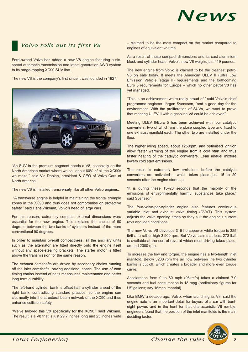
“An SUV in the premium segment needs a V8, especially on the North American market where we sell about 60% of all the XC90s we make,” said Vic Doolan, president & CEO of Volvo Cars of North America.
The new V8 is installed transversely, like all other Volvo engines.
“A transverse engine is helpful in maintaining the frontal crumple zones in the XC90 and thus does not compromise on protective safety,” said Hans Wikman, Volvo’s head of large cars.
For this reason, extremely compact external dimensions were essential for the new engine. This explains the choice of 60 degrees between the two banks of cylinders instead of the more conventional 90 degrees.
In order to maintain overall compactness, all the ancillary units such as the alternator are fitted directly onto the engine itself without any space-stealing brackets. The starter motor is fitted above the transmission for the same reason.
The exhaust camshafts are driven by secondary chains running off the inlet camshafts, saving additional space. The use of cam timing chains instead of belts means less maintenance and better long term durability.
The left-hand cylinder bank is offset half a cylinder ahead of the right bank, contradicting standard practice, so the engine can slot neatly into the structural beam network of the XC90 and thus enhance collision safety.
“We’ve tailored this V8 specifically for the XC90,” said Wikman. The result is a V8 that is just 29.7 inches long and 25 inches wide
Ford-owned Volvo has added a new V8 engine featuring a six-speed automatic transmission and latest-generation AWD system to its range-topping XC90 SUV line.
The new V8 is the company’s first since it was founded in 1927.
Volvo rolls out its first V8
6Lotus Engineering Change the rules
“Our new V8 has just the right sort of charismatic off-beat V8 burble, but it is somewhat more sophisticated than the more traditional meaty American throb” said Svensson.
The V8 is combined with a new six-speed automatic transmission dimensioned to handle high torque. This unit is also of particularly compact dimensions so as not to interfere with the car’s overall structure. Sixth gear is a pure overdrive ratio to ensure quiet cruising and low fuel consumption.
“We get simply massive ‘take-off’ force with this new auto transmission,” said Svensson. “At the same time, it has a very sporty nature and does not change up in the middle of a curve, for instance, but instead stays in the same gear until the bend straightens out.”
The new transmission is a so-called ‘Geartronic’ unit, which means that it can also be shifted manually.
To ensure the optimum balance between driving properties, performance and fuel consumption the engine and transmission are treated as one unit. This is achieved with new software developed by Volvo, called CVC (Complete Vehicle Control). CVC is part of the integrated software package used both in the engine control module and the transmission control module.
Among the many benefits of this approach was the possibility of integrating an overdrive 6th gear while still maintaining good driving performance by adjusting gear and torque to suit current conditions.
The new electronic AWD drive system features ‘Instant Traction’ – a claimed industry first – which considerably improves scope for quick getaways and provides enhanced traction on slippery
News
surfaces. It has been developed by the Swedish company Haldex.
“A non-return valve allows us to use software to control the base torque that is programmed into the AWD system. When starting off from standstill, 59 lb/ft of torque is pre-charged in the system since the non-return valve prevents the unit from becoming totally drained of hydraulic fluid” said Svensson.
“This reduces the usual wheelspin of about one-seventh of a turn that the current system permits before the power is delivered to the rear wheels.”
The AWD system has also been upgraded to handle the power of the V8 engine. Maximum short-term torque at the rear wheels has been increased by 50% compared to other XC90 models.
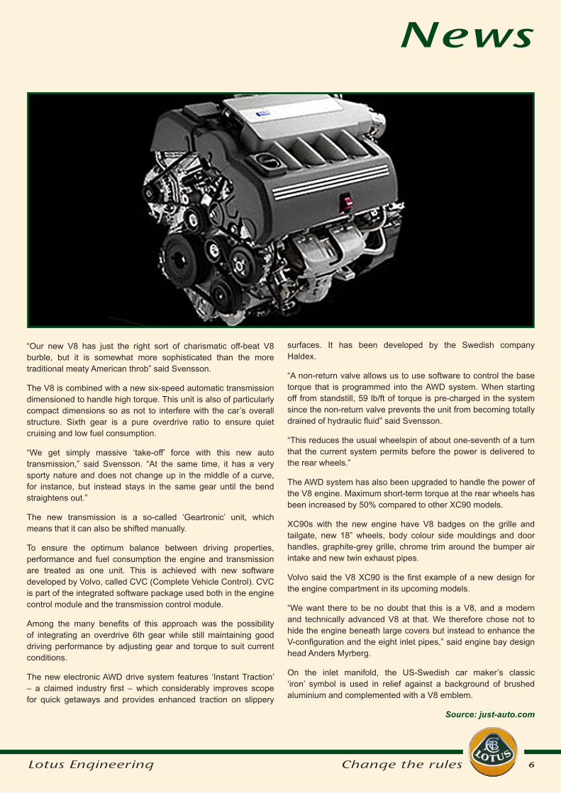
XC90s with the new engine have V8 badges on the grille and tailgate, new 18” wheels, body colour side mouldings and door handles, graphite-grey grille, chrome trim around the bumper air intake and new twin exhaust pipes.
Volvo said the V8 XC90 is the first example of a new design for the engine compartment in its upcoming models.
“We want there to be no doubt that this is a V8, and a modern and technically advanced V8 at that. We therefore chose not to hide the engine beneath large covers but instead to enhance the V-configuration and the eight inlet pipes,” said engine bay design head Anders Myrberg.
On the inlet manifold, the US-Swedish car maker’s classic ‘iron’ symbol is used in relief against a background of brushed aluminium and complemented with a V8 emblem.
Source: just-auto.com
7Lotus Engineering Change the rules
Studies by automotive analysts Frost & Sullivan forecast the automotive fuel cell market will gather pace up to 2008 when revenues will reach up to a sizeable €47.7 million. Small series production could start around this time, gathering momentum to reach revenues of €18.5 billion by 2020 and €52 billion by 2040.
The main competitive arena at the moment is research & development. Frost & Sullivan says: “For companies choosing to be at the forefront of this revolution in automotive powertrain technology, research and development will be imperative, it is where the long term competitive advantage will be created.
“As the race heats up key players are vying to deliver a credible fuel cell powertrain to market within the next two years.”
The US Big Three all have big fuel cell programmes running as do the majority of European automakers. One such programme is Xcellsis, a joint venture set up by Ford, Daimler Chrysler and fuel cell company Ballard Power Systems to produce fuel cell engines.
The road to mass-market depends on a number of things, not least cost. The current cost of a fuel cell engine is in the region of €750 per kW compared to around €20/kW for an internal combustion engine. A significant proportion of the cost element can be attributed to materials. Effective research and development will play a vital role in bringing these costs down and enabling mass production.
Another challenge is the development of the technology and how to produce it - through electrolysis or reformation - and whether this is done on-board or off-board.
Fuel suppliers have yet to map out a clear route to achieve the ultimate goal: a scenario where pure hydrogen can be retailed to users of fuel cell vehicles just as gasoline is today. The industry is facing enormous infrastructure investments, which cannot be recouped in the short to medium term by fuel revenues.
In this sense the auto industry is getting plenty of demand for change, but little help from governments. It is trying to stay ahead of the curve and second-guess any upcoming legislation.
Volkswagen, one of the pioneers of the hybrid car a few years back, is again taking a primary role in improving fuel economy as the leading partner in a €5 million European Union research project into the creation of ultra-light cars.
The initiative, led by VW, boasts fifteen partners, including Volvo, Renault and DaimlerChrysler. Along with a host of research organisations throughout Europe, it is bidding to help develop the new generation of energy efficient automobiles.
Named TECABS - Technologies for Carbon Fibre Modular Automotive Structures - the project aims to provide the technology to halve body weight using low cost carbon composite structures, thereby reducing CO2 emissions.
Look through the annual accounts of any automotive company, be it carmaker or supplier, and one of the interesting figures to look out for is the research and development spend as a percentage of turnover. Although it varies from company to company, the percentage is generally within a few points of each other, and it adds up to billions of dollars a year.
But it is a spend that by and large goes unrecognised by the consumer or indeed by the legislators or environmental lobbyists around the world. The automotive industry is regularly hung out to dry whenever there is talk of greenhouse gases, pollution or road safety issues.
None of this takes into account the great strides the industry has made in all these areas over the past couple of decades - always at its own expense and on its own initiative.
A large proportion of the R&D spend in this time has gone on propulsion systems and how to squeeze the greatest number of miles to the gallon while causing the least damage to the environment. While diesel currently remains the best option, the search for the Holy Grail - an alternative to oil-based fuel - continues.
Car makers and suppliers have joined forces in the task of researching and developing fuel cells, the industry’s best hope of being able to sustain individual mobility in the new millennium by delivering ‘clean’ energy to power automobiles.
The rapid depletion in global stocks of crude oil over the next fifty years, harmful pollutants in the atmosphere - principally Carbon Monoxide (CO) and Nitrogen Oxides (NOx) from the combustion of fossil fuels – and the cost of energy, all pose a threat to the traditional internal combustion engine.
Automotive industry R&D
and the unseen billions
Feature
8Lotus Engineering Change the rules
Feature
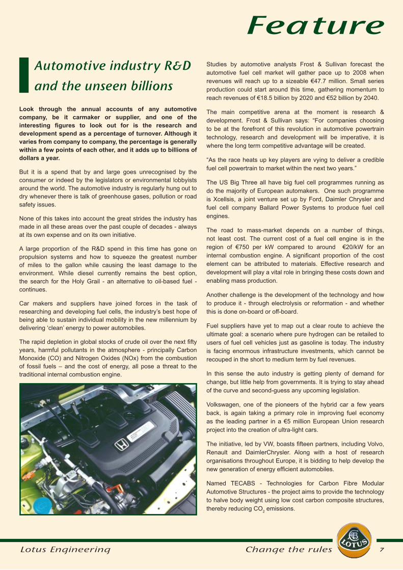
Meanwhile, petrol engines are becoming more efficient. VW and Renault are working on a 1-litre petrol turbocharged unit designed to produce the same power as a conventional 1.6 litre motor: effectively offering a 30 per cent reduction in fuel consumption.
If the research projects are successful, the next generation environment-friendly cars will have only 30 percent of the current number of body parts, cutting assembly costs to make this an affordable option for the man in the street.
What’s more, research and development can throw up all sorts of interesting problems. For example using a new material could call into question the traditional shape of cars as we know them leading to a new concept in body parts and shape. It could be cigar shaped and car companies admit they don’t know how the public might respond to such a concept.
The partners in the EU project are not the only ones with their eye on lightweight cars. The Toyota Prius and Honda Insight, both now on sale in Japan, the United States and Europe, use differing combinations of electric and petrol engines at up to 2.75 litres/100km (103 miles per gallon).
To achieve the necessary economies, research into production processes will clearly be key. While it is easy to make a lightweight prototype - Formula One has been doing so for many years - the challenge of mass production will be paramount. High speed and low cost manufacturing production processes using cost effective and quick preform and resin processes will be employed.
But Research and Development is not all about the environment and how to build cars. With increasing technology available, there is an issue as to how the driver can interact with everything now available. After all, car drivers are not jet pilots.
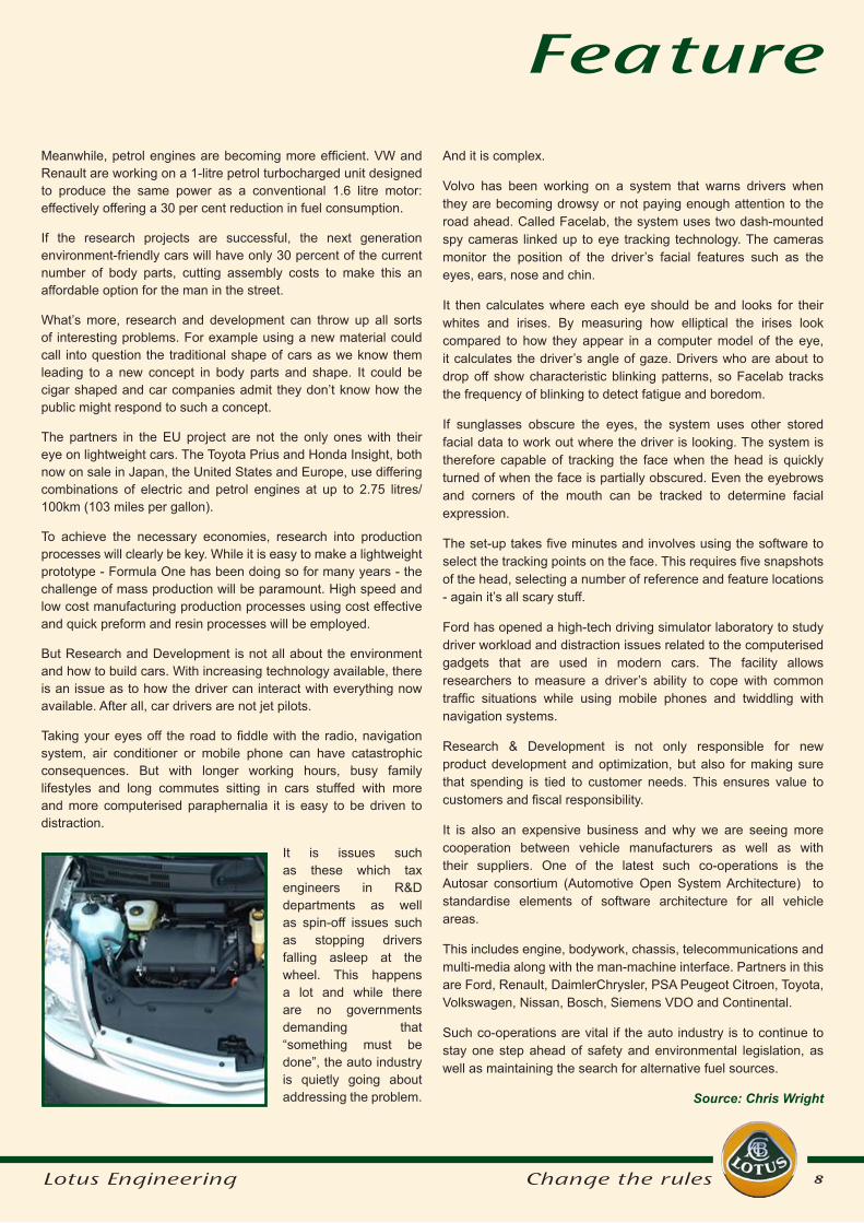
Taking your eyes off the road to fiddle with the radio, navigation system, air conditioner or mobile phone can have catastrophic consequences. But with longer working hours, busy family lifestyles and long commutes sitting in cars stuffed with more and more computerised paraphernalia it is easy to be driven to distraction.
It is issues such as these which tax engineers in R&D departments as well as spin-off issues such as stopping drivers falling asleep at the wheel. This happens a lot and while there are no governments demanding that “something must be done”, the auto industry is quietly going about addressing the problem.
And it is complex.
Volvo has been working on a system that warns drivers when they are becoming drowsy or not paying enough attention to the road ahead. Called Facelab, the system uses two dash-mounted spy cameras linked up to eye tracking technology. The cameras monitor the position of the driver’s facial features such as the eyes, ears, nose and chin.
It then calculates where each eye should be and looks for their whites and irises. By measuring how elliptical the irises look compared to how they appear in a computer model of the eye, it calculates the driver’s angle of gaze. Drivers who are about to drop off show characteristic blinking patterns, so Facelab tracks the frequency of blinking to detect fatigue and boredom.
If sunglasses obscure the eyes, the system uses other stored facial data to work out where the driver is looking. The system is therefore capable of tracking the face when the head is quickly turned of when the face is partially obscured. Even the eyebrows and corners of the mouth can be tracked to determine facial expression.
The set-up takes five minutes and involves using the software to select the tracking points on the face. This requires five snapshots of the head, selecting a number of reference and feature locations - again it’s all scary stuff.
Ford has opened a high-tech driving simulator laboratory to study driver workload and distraction issues related to the computerised gadgets that are used in modern cars. The facility allows researchers to measure a driver’s ability to cope with common traffic situations while using mobile phones and twiddling with navigation systems.
Research & Development is not only responsible for new product development and optimization, but also for making sure that spending is tied to customer needs. This ensures value to customers and fiscal responsibility.
It is also an expensive business and why we are seeing more cooperation between vehicle manufacturers as well as with their suppliers. One of the latest such co-operations is the Autosar consortium (Automotive Open System Architecture) to standardise elements of software architecture for all vehicle areas.
This includes engine, bodywork, chassis, telecommunications and multi-media along with the man-machine interface. Partners in this are Ford, Renault, DaimlerChrysler, PSA Peugeot Citroen, Toyota, Volkswagen, Nissan, Bosch, Siemens VDO and Continental.
Such co-operations are vital if the auto industry is to continue to stay one step ahead of safety and environmental legislation, as well as maintaining the search for alternative fuel sources.
Source: Chris Wright
9Lotus Engineering Change the rules
The key developments in powertrain technology are driven by legislative and self regulation demands in the face of increasing global environmental standards. For emissions, clean air demands means reduction of toxic gas emissions - CO, HC, NOx & particulates (pm). In Europe, legislation is driving emissions levels down to 5% of Euro 1 levels. For diesel engines, the NOx vs Particulates trade-off is a challenge.
Global warming countermeasures are demanding reduction of CO2 to be achieved through burning less fuel. The Kyoto protocol requires dramatic improvements in fuel economy and European OEMs have made voluntary commitments to achieve corporate fleet average CO2 of 140g/Km in 2008 and stretch targets of 120 g/Km in 2012.
To achieve this the gasoline engine needs to develop improved fuel economy and the diesel engine needs to achieve reductions in Nox & PM emissions. Emissions aftertreatments are driving up engine Bill of Material costs and solutions are required to allow OEMs to achieve return on investment for new engine developments. Finally OEMs are also demanding the flexibility to develop niche high performance derivative engines to enhance brand image and satisfy rapidly changing end customer demands.
Lotus is responding to these challenges by engaging in powertrain technology developments in the following areas and these projects are described in more detail below:
Feature
Powertrain
Automotive
Technology
Developments
at Lotus
Variable Valvetrain Systems
Since 1992, Lotus has developed a range of Variable Valvetrain systems to demonstrate benefits. One example is the development of a Mechanically Variable Valvetrain (MVVT) system, with principles similar to BMW Valvetronic system, to optimise engine performance.
Reduced pumping losses due to throttleless operation also lead to benefits in fuel economy - 15% reduction in fuel consumption has been predicted. These systems exist as ‘Bookshelf’ designs and are available under licence from Lotus.
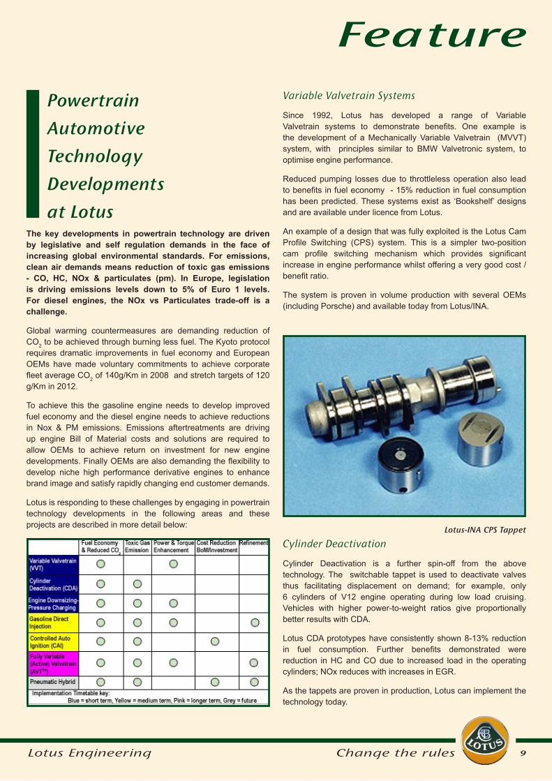
An example of a design that was fully exploited is the Lotus Cam Profile Switching (CPS) system. This is a simpler two-position cam profile switching mechanism which provides significant increase in engine performance whilst offering a very good cost / benefit ratio.
The system is proven in volume production with several OEMs (including Porsche) and available today from Lotus/INA.
Cylinder Deactivation
Cylinder Deactivation is a further spin-off from the above technology. The switchable tappet is used to deactivate valves thus facilitating displacement on demand; for example, only 6 cylinders of V12 engine operating during low load cruising. Vehicles with higher power-to-weight ratios give proportionally better results with CDA.
Lotus CDA prototypes have consistently shown 8-13% reduction in fuel consumption. Further benefits demonstrated were reduction in HC and CO due to increased load in the operating cylinders; NOx reduces with increases in EGR.
As the tappets are proven in production, Lotus can implement the technology today.
Lotus-INA CPS Tappet
10Lotus Engineering Change the rules
Feature
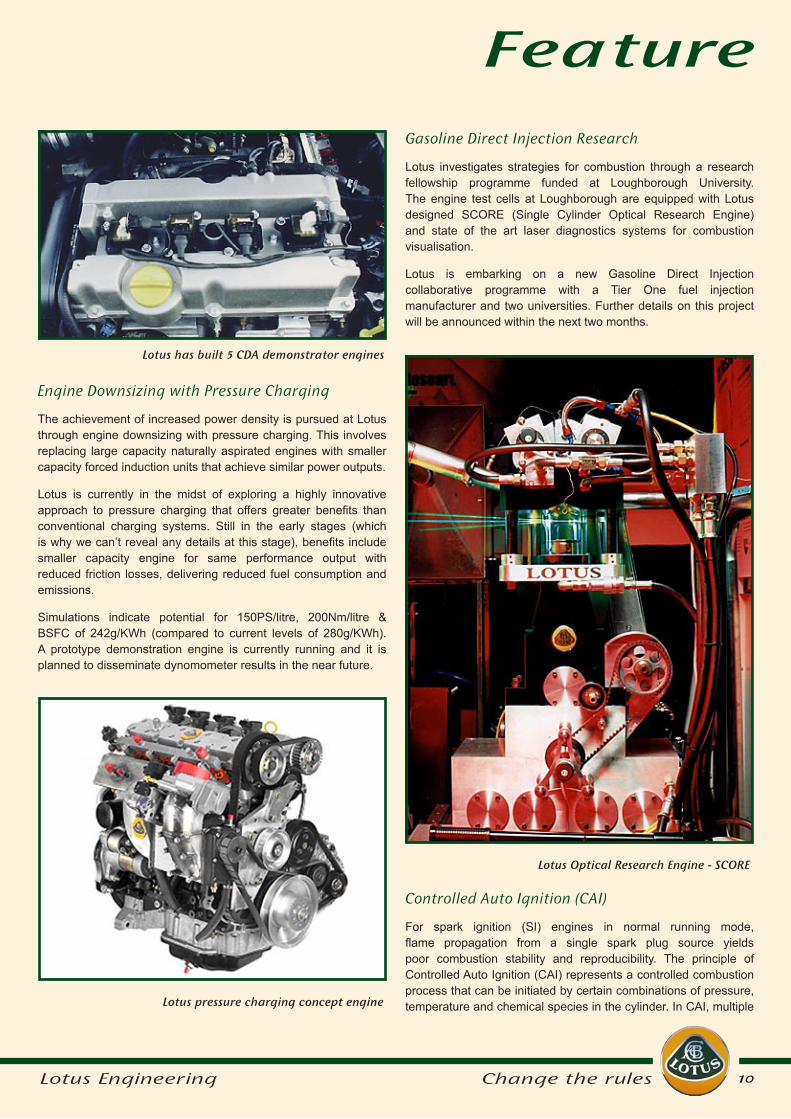
Engine Downsizing with Pressure Charging
The achievement of increased power density is pursued at Lotus through engine downsizing with pressure charging. This involves replacing large capacity naturally aspirated engines with smaller capacity forced induction units that achieve similar power outputs.
Lotus is currently in the midst of exploring a highly innovative approach to pressure charging that offers greater benefits than conventional charging systems. Still in the early stages (which is why we can’t reveal any details at this stage), benefits include smaller capacity engine for same performance output with reduced friction losses, delivering reduced fuel consumption and emissions.
Simulations indicate potential for 150PS/litre, 200Nm/litre & BSFC of 242g/KWh (compared to current levels of 280g/KWh). A prototype demonstration engine is currently running and it is planned to disseminate dynomometer results in the near future.
Lotus pressure charging concept engine
Lotus has built 5 CDA demonstrator engines
Gasoline Direct Injection Research
Lotus investigates strategies for combustion through a research fellowship programme funded at Loughborough University. The engine test cells at Loughborough are equipped with Lotus designed SCORE (Single Cylinder Optical Research Engine) and state of the art laser diagnostics systems for combustion visualisation.
Lotus is embarking on a new Gasoline Direct Injection collaborative programme with a Tier One fuel injection manufacturer and two universities. Further details on this project will be announced within the next two months.
Lotus Optical Research Engine - SCORE
Controlled Auto Ignition (CAI)
For spark ignition (SI) engines in normal running mode, flame propagation from a single spark plug source yields poor combustion stability and reproducibility. The principle of Controlled Auto Ignition (CAI) represents a controlled combustion process that can be initiated by certain combinations of pressure, temperature and chemical species in the cylinder. In CAI, multiple
11Lotus Engineering Change the rules
Featureignition sites can be achieved which have the effect of promoting combustion stability and refined running.
It is possible to achieve auto ignition, sometimes even without spark, in the low load region of the engine operating map by utilising high levels of exhaust gas recirculation (EGR). These levels of EGR are achieved by flexible exhaust valve events. The high levels of EGR, with associated high temperature, mixed with fresh charge allows multiple ignition points to be achieved throughout the cylinder without spark.
To investigate the limits of CAI operation, Lotus has used the AVTTM system (see below for details) which allows fully variable valve events. Major benefits have been demonstrated in improved combustion stability & refinement, 20% reduction in fuel consumption, 95% reduction in NOx emissions and 30% reduction in HC, CO emissions. It is also possible to run cheaper alternative fuels.
Lotus’ is now evaluating the cost/benefit ratio of CAI with valve events dictated by more conventional two stage switching systems which represent today’s technology at affordable BoM costs.
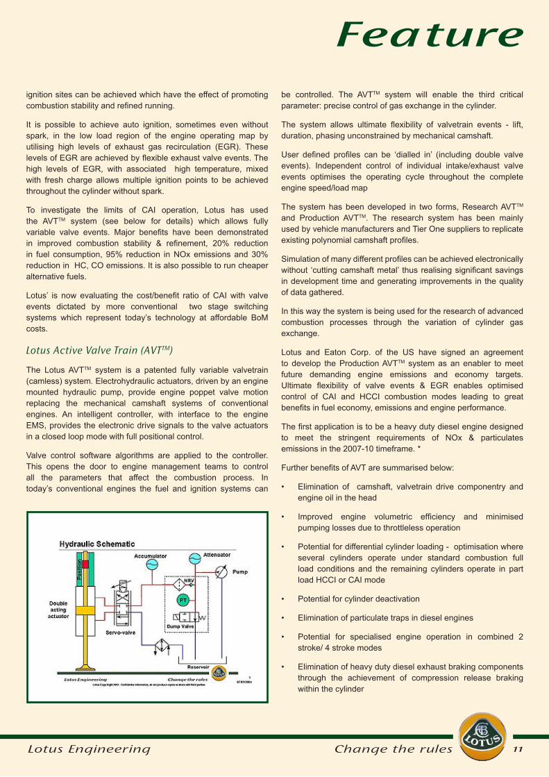
Lotus Active Valve Train (AVTTM)
The Lotus AVTTM system is a patented fully variable valvetrain (camless) system. Electrohydraulic actuators, driven by an engine mounted hydraulic pump, provide engine poppet valve motion replacing the mechanical camshaft systems of conventional engines. An intelligent controller, with interface to the engine EMS, provides the electronic drive signals to the valve actuators in a closed loop mode with full positional control.
Valve control software algorithms are applied to the controller. This opens the door to engine management teams to control all the parameters that affect the combustion process. In today’s conventional engines the fuel and ignition systems can
be controlled. The AVTTM system will enable the third critical parameter: precise control of gas exchange in the cylinder.
The system allows ultimate flexibility of valvetrain events - lift, duration, phasing unconstrained by mechanical camshaft.
User defined profiles can be ‘dialled in’ (including double valve events). Independent control of individual intake/exhaust valve events optimises the operating cycle throughout the complete engine speed/load map
The system has been developed in two forms, Research AVTTM
and Production AVTTM. The research system has been mainly used by vehicle manufacturers and Tier One suppliers to replicate existing polynomial camshaft profiles.
Simulation of many different profiles can be achieved electronically without ‘cutting camshaft metal’ thus realising significant savings in development time and generating improvements in the quality of data gathered.
In this way the system is being used for the research of advanced combustion processes through the variation of cylinder gas exchange.
Lotus and Eaton Corp. of the US have signed an agreement to develop the Production AVTTM system as an enabler to meet future demanding engine emissions and economy targets. Ultimate flexibility of valve events & EGR enables optimised control of CAI and HCCI combustion modes leading to great benefits in fuel economy, emissions and engine performance.
The first application is to be a heavy duty diesel engine designed to meet the stringent requirements of NOx & particulates emissions in the 2007-10 timeframe. *
Further benefits of AVT are summarised below:
Elimination of camshaft, valvetrain drive componentry and engine oil in the head
Improved engine volumetric efficiency and minimised pumping losses due to throttleless operation
Potential for differential cylinder loading - optimisation where several cylinders operate under standard combustion full load conditions and the remaining cylinders operate in part load HCCI or CAI mode
Potential for cylinder deactivation
Elimination of particulate traps in diesel engines
Potential for specialised engine operation in combined 2 stroke/ 4 stroke modes
Elimination of heavy duty diesel exhaust braking components through the achievement of compression release braking within the cylinder
•
•
•
•
•
•
•
12Lotus Engineering Change the rules
systems but at significantly lower power unit BoM cost.
Lotus is conducting some fundamental research and is currently negotiating a 3 year collaborative research programme with two universities and two OEMs (OEMs provide vehicle application and duty cycle). New OEM partners are invited to collaborate.
Conclusion
As an automotive consultancy, Lotus has long recognised the need for investment in new technology developments to thrive in an increasingly competitive market. OEMs are facing growing social and economic demands from end customers that are driving rapid technology developments in automotive propulsion units. The projects described above illustrate that Lotus responds to these demands through a combination of evolutionary developments to optimise performance of current IC engines and more radical research into new power unit concepts.
Finally, look out for a summary of Lotus technology developments in vehicle projects which will be featured in a future issue of pro-Active.
Source: Oliver Shearman, Head of Research & Technologies, Lotus Engineering
Flexible engine - develop sport variant of base engine through S/W parameter changes
More efficient, cleaner engine starting strategies, potentially allowing the starter motor and battery to be downsized
Pneumatic Hybrid
Recent developments in IC engine / electric hybrid vehicles use expensive electrical starter/generator systems.
Lotus is researching a pneumatic hybrid system whereby the ‘hybridisation’ occurs within the IC engine itself.
On the overrun and during vehicle braking the engine pumps compressed air to an accumulator tank. By subsequently venting from the accumulator, the engine can operate as an air motor to launch the vehicle from start (no engine idling) and for torque assist during acceleration.
AVTTM is the enabler - fully flexible actuation of a dedicated engine valve allows efficient accumulator charging.
CAE modelling feasibility studies indicate the potential for the system to operate effectively with a two-litre four-cylinder engine charging a 30 litre accumulator tank.
The potential exists to obtain the reduced fuel consumption and emissions levels associated with current mild electric hybrid
•
•
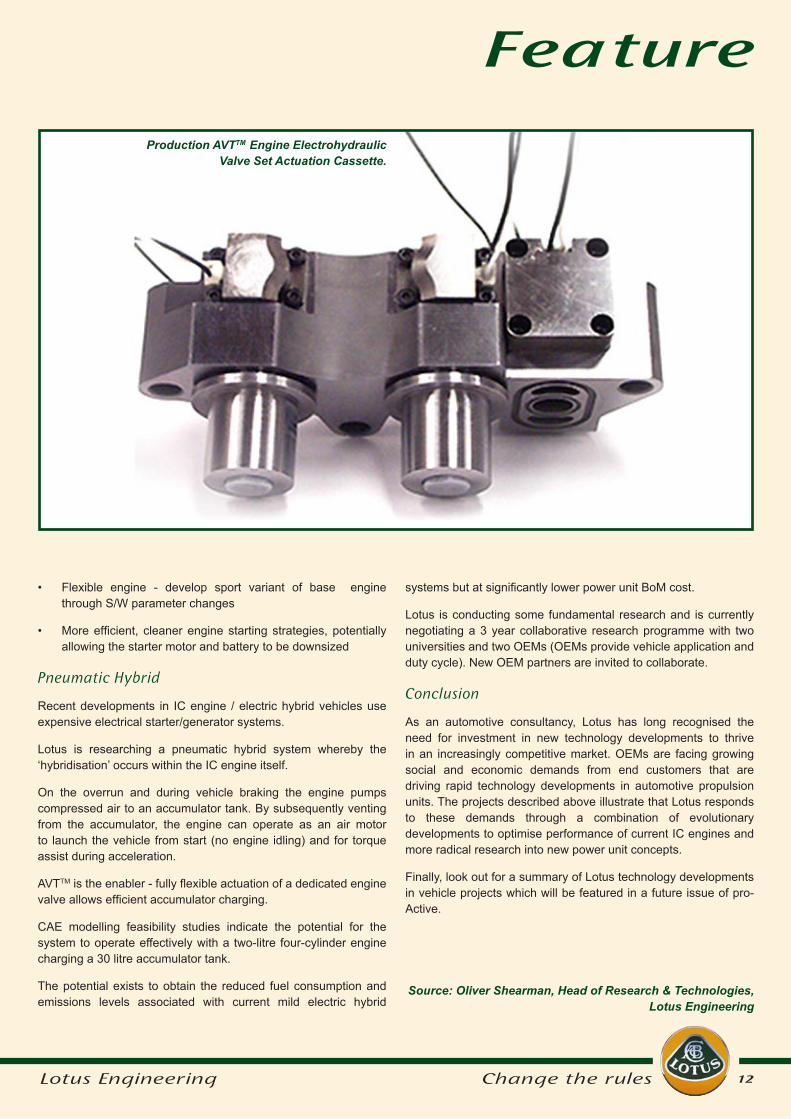
Production AVTTM Engine Electrohydraulic Valve Set Actuation Cassette.
Feature
13Lotus Engineering Change the rules
FeatureEngineering has been able to achieve considerable time reduction through eliminating this cycle.
To understand where the improvements have been achieved, and to gain an insight into the extent of those gains, it is necessary first to understand the traditional suspension design and optimisation process and to quantify its efficiency.
Here, we will look at a case study of the suspension design process undertaken for a new vehicle platform.
Traditional Suspension Design Process
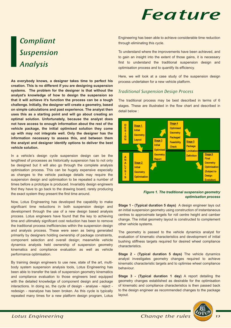
The traditional process may be best described in terms of 6 stages. These are illustrated in the flow chart and described in detail below :
As everybody knows, a designer takes time to perfect his creation. This is no different if you are designing suspension systems. The problem for the designer is that without the analyst’s knowledge of how to design the suspension so that it will achieve it’s function the process can be a tough challenge. Initially, the designer will create a geometry, based on simple calculations and past experience. The analyst then uses this as a starting point and will go about creating an optimal solution. Unfortunately, because the analyst does not have access to enough information about the rest of the vehicle package, the initial optimised solution they come up with may not integrate well. Only the designer has the information necessary to assess this, and between them the analyst and designer identify options to deliver the best vehicle solution.
In a vehicle’s design cycle suspension design can be the lengthiest of processes as historically suspension has to not only be designed but it will also go through the complete analysis optimisation process. This can be hugely expensive especially as changes to the vehicle package details may require the suspension design and optimisation to be repeated a number of times before a prototype is produced. Invariably design engineers find they have to go back to the drawing board, rarely producing the exact system they present the first time around.
Now, Lotus Engineering has developed the capability to make significant time reductions in both suspension design and development through the use of a new design based analysis process. Lotus engineers have found that the key to achieving time and ultimately significant cost reduction has been to remove the traditional process inefficiencies within the suspension design and analysis process. These were seen as being generated primarily by designers holding ownership of package constraints, component selection and overall design; meanwhile vehicle dynamics analysts held ownership of suspension geometry kinematics and compliance evaluation as well as vehicle performance optimisation.
By training design engineers to use new, state of the art, multi-body system suspension analysis tools, Lotus Engineering has been able to transfer the task of suspension geometry kinematics and compliance evaluation to those engineers best equipped with the detailed knowledge of component design and package interactions. In doing so, the cycle of design - analyse - reject - redesign - reanalyse has been broken. As this cycle is typically repeated many times for a new platform design program, Lotus
Feature
Stage 1 - (Typical duration 5 days) A design engineer lays out an initial suspension geometry using construction of instantaneous centres to approximate targets for roll centre height and camber change. The initial geometry layout is constructed to complement other vehicle systems.
The geometry is passed to the vehicle dynamics analyst for evaluation of kinematic characteristics and development of initial bushing stiffness targets required for desired wheel compliance characteristics.
Stage 2 - (Typical duration 5 days) The vehicle dynamics analyst investigates geometry changes required to achieve kinematic characteristic targets and to optimise wheel compliance behaviour.
Stage 3 - (Typical duration 1 day) A report detailing the geometry changes established as desirable for the optimisation of kinematic and compliance characteristics is then passed back to the design engineer as recommended changes to the package layout.
Figure 1. The traditional suspension geometry optimisation process
Compliant
Suspension
Analysis
14Lotus Engineering Change the rules
FeatureStage 4 - (Typical duration 5 days) The design engineer reviews the geometry change recommendations received in relation to the total vehicle package. This typically will result in only a partial acceptance of the recommendations made by the vehicle dynamics analyst.
Stage 5 - (Typical duration 1 day) The design engineer and vehicle dynamics analyst discuss the of extent of geometry change acceptability to the vehicle package and any alternative options for further geometry improvement.
Stage 6 - (Typical duration 5 days) The vehicle dynamics analyst investigates further geometry changes reflecting the packagable options established during Stage 5 to achieve the best compromise of kinematic and compliance characteristics.
From Lotus’ experience, the initial process may take 4 weeks, and each subsequent revision of the suspension geometry could typically take a further week of analysis and design time. Assuming twenty investigations of potential suspension geometry revision during the design program, this equates to 24 weeks of design / analysis time per axle, or 48 weeks per project.
Process Improvements
To improve the efficiency of the process, Lotus placed the responsibility for suspension geometry optimisation with the suspension design team.
Lotus has, for many years, used a suspension kinematic analysis program, written in house for its own use. The importance and influence of system compliance had meant that the use of this tool had been restricted to being an aid to the development of the initial package layout in Stage 1 of the process described above. However, it did possess certain attractive features.
Firstly, it was a user friendly, dedicated suspension analysis tool, with templates for common suspension linkage types, and built in calculation routines for the automatic generation of suspension characteristic derivatives.
Secondly, an engineer with a basic knowledge of vehicle suspensions could use it productively with minimal training (Lotus had demonstrated this with engineering undergraduates with little or no vehicle engineering experience).
Thirdly, and most importantly, it combined the geometry change, analysis and post processing stages into one simultaneous activity. Within the programme kinematic suspension characteristic graphs update simultaneously as the operator drags hardpoint positions with a mouse. By analysing and presenting the suspension kinematic characteristics in real time, as the operator manipulated the suspension geometry through a 3D pick and drag graphical interface, a new level of intuitive interaction and system optimisation speed was achieved.
If the mathematical model behind the software could be expanded to include adequate representation of system compliance, whilst
maintaining its real time solution, then it had the potential to facilitate the process improvements Lotus envisaged.
Lotus Engineering Suspension Analysis (LSA)
In order to encompass system compliance, a new mathematical model was developed by Lotus’ CAE group. Whilst retaining the use of templates for system definition, the new model was generic, as opposed to the system specific models used in the previous kinematic code.
This would enable new templates to be easily developed by the user through specification of the number of bodies, their connectivity and nature of the connection using a simple tabular format dialogue window.
The considerable advances in PC hardware capabilities in recent years meant that real time solution of a compliant suspension system model was now a practical reality.
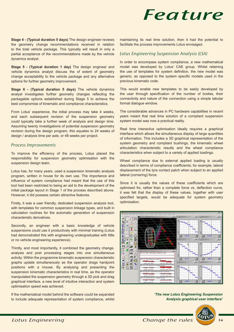
Real time interactive optimisation ideally requires a graphical interface which allows the simultaneous display of large quantities of information. This includes a 3D graphical representation of the system geometry and compliant bushings, the kinematic wheel articulation characteristic results and the wheel compliance characteristics when subject to a variety of applied loadings.
Wheel compliance due to external applied loading is usually described in terms of compliance coefficients; for example, lateral displacement of the tyre contact patch when subject to an applied lateral (cornering) force.
Since it is usually the values of these coefficients which are optimised for, rather than a complete force vs. deflection curve, it was felt that the display of these values, together with user specified targets, would be adequate for system geometry optimisation.
‘The new Lotus Engineering Suspension Analysis graphical user interface’
15Lotus Engineering Change the rules
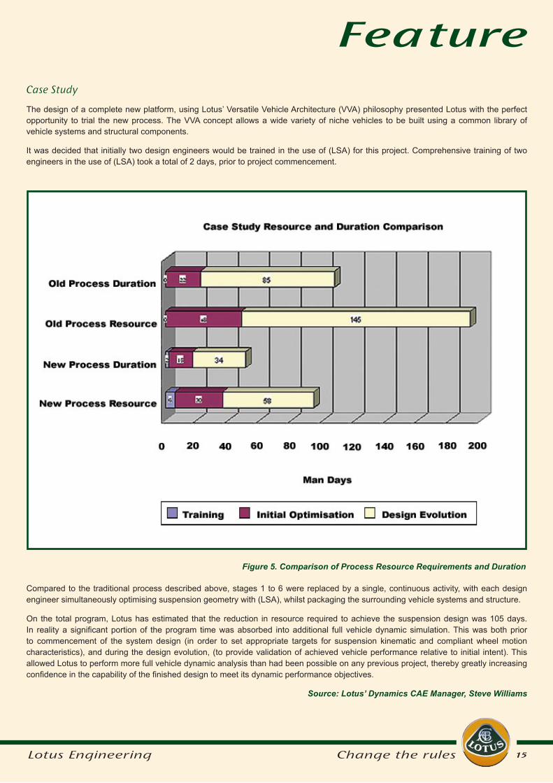
Compared to the traditional process described above, stages 1 to 6 were replaced by a single, continuous activity, with each design engineer simultaneously optimising suspension geometry with (LSA), whilst packaging the surrounding vehicle systems and structure.
On the total program, Lotus has estimated that the reduction in resource required to achieve the suspension design was 105 days. In reality a significant portion of the program time was absorbed into additional full vehicle dynamic simulation. This was both prior to commencement of the system design (in order to set appropriate targets for suspension kinematic and compliant wheel motion characteristics), and during the design evolution, (to provide validation of achieved vehicle performance relative to initial intent). This allowed Lotus to perform more full vehicle dynamic analysis than had been possible on any previous project, thereby greatly increasing confidence in the capability of the finished design to meet its dynamic performance objectives.
Source: Lotus’ Dynamics CAE Manager, Steve Williams
Figure 5. Comparison of Process Resource Requirements and Duration
Case Study
The design of a complete new platform, using Lotus’ Versatile Vehicle Architecture (VVA) philosophy presented Lotus with the perfect opportunity to trial the new process. The VVA concept allows a wide variety of niche vehicles to be built using a common library of vehicle systems and structural components.
It was decided that initially two design engineers would be trained in the use of (LSA) for this project. Comprehensive training of two engineers in the use of (LSA) took a total of 2 days, prior to project commencement.
Feature
16Lotus Engineering Change the rules
Put an average driver on a test track where they can explore their car’s limits in safety and most will quickly work out how hard they can brake without provoking a skid. Similarly they’ll soon discover the limits of cornering adhesion. But ask most people to do both at the same time and they’re in trouble.
When you brake in a straight line, you’re using the tyre’s capacity to grip in the direction you’re travelling. In the case of cornering you’re using lateral capacity. The more capacity you use in one direction, the less is available in the other. Most people can sense the limits in one direction at a time, but if you’re using 50% of the tyre’s capacity longitudinally, it’s hard to tell how much you’ve got left laterally. F1 drivers excel at optimally exploiting the capacity of the tyre in both directions simultaneously.
Suppose you could devise an electronic box of tricks to do this job for you? Not surprisingly, Lotus are very interested in this. Electronic systems to improve vehicle stability are now commonplace. Most people are familiar with anti-lock braking. Traction control takes ABS a stage further, allowing the driven wheels to be braked individually if they start to lose adhesion under hard acceleration or on a slippery surface. Stability control goes further still, and adds sensors to detect if the car is losing grip while cornering (technically it senses whether the car’s yaw rate is greater than you would expect for the
Controlled
Vehicle
Dynamics (CVD),
- Is this next
generation
vehicle stability?
amount of steering input) and applies the brakes to apply counteracting forces.
Some manufacturers have marketed cars with elements of an active suspension system. Citroen produced a Xantia with active roll control. The Land Rover Discovery uses electronic roll control to reconcile off-road and on-road. Jaguar’s CATS adaptive damping system modifies the ride softness. Mercedes-Benz’s Active Body control changes the spring characteristics.
In general, these are systems to manage the car’s stability better. The aim is a system which allows the car’s behaviour to be controlled, rather than just managed, under all conditions up to the limit of adhesion, optimising the forces between the tyre and road surface — the electronic equivalent of the F1 driver.
Lotus calls this Controlled Vehicle Dynamics or CVD. It manages the whole vehicle to follow the optimum path from one position to the next.
CVD would control simultaneously both lateral and longitudinal slip, and would incorporate active suspension to control the distribution of loads to each tyre, giving the maximum possible control over forces
between the tyre and the road.
Sufficient electronic tools have been developed to allow CVD to be achieved in a variety of ways. Lotus itself has been experimenting with active control systems since 1981, when it first developed active suspension for F1 cars. Potentially at the disposal of the car designer, is a menu of controls affecting braking, suspension, steering and transmission systems.
An integrated approach to design allows a subset of available systems to do everything that’s needed at lower cost.
Lotus Engineering believes that adding rear wheel steer and active suspension to today’s ABS/traction control and stability control will do the job of handling the five types of inputs which have an effect on the vehicle chassis: longitudinal (acceleration and braking), lateral (cornering), vertical ride inputs (bumps on the road), aerodynamic (wind) and transient (anything which is not steady-state such as a sudden steering movement to avoid an obstacle).
Rear wheel steering might sound like a slightly worrying concept to many drivers, but Honda used a system in its Integra coupe in the 1990s. This was a
Feature
17Lotus Engineering Change the rules
to be thrown forward under braking or to one side under cornering, both of which allow the other less heavily loaded tyres to lose grip.
A powerful factor in an active suspension set up would be twin channel roll control, as distinct from the Discovery’s single channel version. Twin channels allow the front and rear of the car to be treated separately, allowing the balance between understeer and oversteer to be optimised.
Lotus envisages two levels of signal processing for CVD, with a central master processor to interpret inputs from sensors around the car and decide which system or systems to deploy — for example, rear steer would be preferable to ABS if the system detected a lack of grip due to a slippery surface — while intelligent units at each wheel would then handle the response, communicating with the central processor via a synchronous messaging bus.
One problem which could hold up development of a car in which electronics is so integral is the question of how to deal with battery failure in a fail-safe way — unless a battery with much longer
guaranteed life than the current three years or so becomes available. Another problem, which at first glance does not appear especially problematic, is the question of the failure of an actuator. A CVD system would be so sophisticated that to a large extent the functioning actuators could automatically compensate for a faulty one. This could leave the driver unaware of the problem or at least with no incentive to get it fixed. So it might be necessary to artificially degrade the performance in a way that was safe but also impossible to ignore.
Lotus are convinced of the potential of CVD. It will homogenise vehicle behaviour across all conditions. It will make the car more responsive and fun to drive. Customers will benefit from better steering feel, car body control and refinement and carmakers like Lotus will be better able to meet growing customer demand for cars which are fun to drive but safe.
Adapted from a feature first published in ‘The Engineer’ Lotus Engineering
would like to thank ‘The Engineer’ and Journalist David Fowler for their kind
permission to reprint this article.
mechanical system with no feedback, so it was limited, but it improved transient response for manoeuvres such as lane changes. Undisputedly, rear wheel steer is a good way of introducing stability.
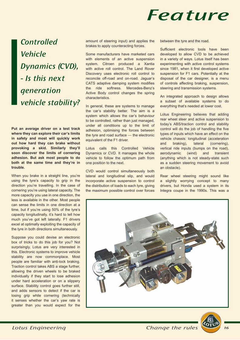
Lotus is currently re-evaluating how to apply rear wheel steer. An active system could compensate for bump steer (unintended direction changes caused by hitting bumps) and cross winds; it could correct understeer or oversteer (when the front or rear starts to lose grip when cornering), and counteract changes in the friction between tyre and road (for example if one wheel hits a patch of oil or ice while the other remains on dry tarmac).
All these stability improvements can be achieved using rear steering angles of only 1–2deg, for which electric actuators are sufficient. Higher angles of up to 10deg can help with low speed manoeuvring but would need more expensive, bulkier and heavier hydraulic actuators.
Active suspension has a great deal of potential because it can have an impact on all five types of input. A hydraulic or electronic actuator at each wheel would counteract the tendency of the car’s weight
Feature
Group Lotus plc
Head office:Lotus Cars Ltd
HethelNorwichNorfolk
NR14 8EZUnited Kingdom
Editor: Ann-Marie JonesE: [email protected]
just-auto.com
Head office:C/o Aroq Ltd
Seneca HouseBuntsford Park Road
BromsgroveB60 3DX
United Kingdom
Contact: Mike GoveE: [email protected]
This newsletter was produced for Lotus Engineering by Aroq Ltd. © 2004 All content copyright Group Lotus plc and Aroq Ltd.


![Progress in Camless Variable Valve Actuation with Two ... Articles/Progress in camless variable...camless technologies in emission reduction as well as fuel economy [17]. A family](https://img.pdfslide.us/doc/110x75/5aa889937f8b9a6c188bb001/progress-in-camless-variable-valve-actuation-with-two-articlesprogress-in-camless.jpg)