Embed Size (px)
Citation preview
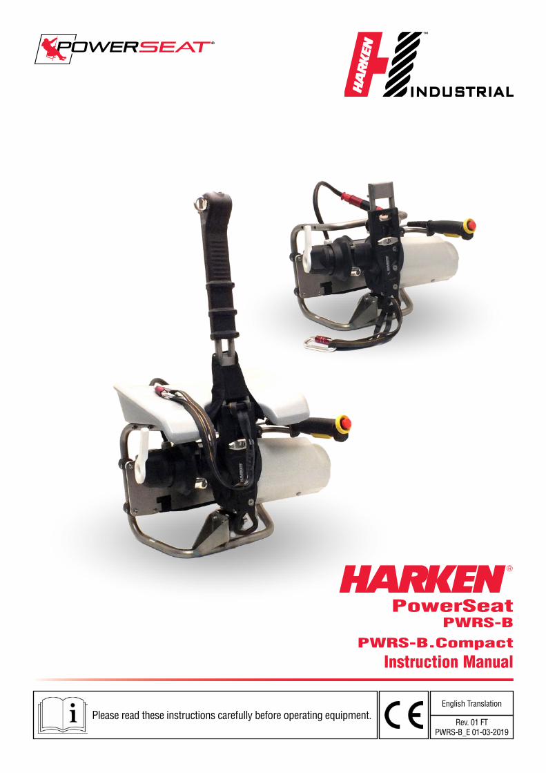
PowerSeatPWRS-B
PWRS-B.Compact
Instruction Manual
Please read these instructions carefully before operating equipment.English Translation
Rev. 01 FTPWRS-B_E 01-03-2019


01-03-19 ENGLISH 3/56

4/56 ENGLISH 01-03-19

01-03-19 ENGLISH 5/56
Introduction
About this Manual
Glossary and Symbols
General Information
Identification Data and Plates on the Device
Model of Declaration of Compliance
Standard References
FCC Verification
IC Certification
Technical Support Information
Safety Precaution
General Advice
Intended Use
Improper Use
Safety Devices
Personal Protective Equipment (PPE)
Residual Risks
Informations on the Power System
Battery Description
General
Technical Data
Light Interface
Safety Informations
Using the Battery
Charge the Battery
Store and Shipping
PowerSeat PWRS-B
Device Description
General
Dimensions
Safe Working Load
Rope Requirements
Vibration
Noise Emission
Technical Data
Motor
Using the Device
Checking the Device Before Use
Index
7
7
8
9
9
10
11
12
12
12
13
13
13
14
14
14
14
16
16
16
17
17
17
18
19
20
22
22
22
23
24
24
24
24
24
25
25
25
page
page
page
page
page
page
page
page
page
page
page
page
page
page
page
page
page
page
page
page
page
page
page
page
page
page
page
page
page
page
page
page
page
page
page
page
page
page
6/56 ENGLISH 01-03-19
Index
Adjusting the Accelerator Control Position
Adjusting the Control Lever Position
Primary Rope Installation Procedure
Wiring the Battery
Preparing to Ascent
Ascent Procedure 1
Ascent Procedure 2
Using PowerSeat with a fixed Anchorage
Descent Procedure 1
Descent Procedure 2
Fixed Anchorage Descent Procedure
Transport and Storage
PowerSeat PWRS-B.Compact
Description of Compact version
General
Dimension
Using the Compact version Device
Checking the Compact version Device Before Use
Primaru Rope Installation Procedure on Compact version
Preparing to Ascent with the Compact version
Ascent Porcedure with the Compact version
Using Compact version PowerSeat with a Fixed Anchorage
Descent Procedure with the Compact version
Fixed Anchorage Descent Procedure with the Compact version
Converting the PowerSeat PWRS-G inthe Compact version
Maintenance
Cleaning
Maintenance
Dismalting and Disposal
Diagnosis and Fault Finding
PowerSeat and Motor
Battery
Maintenance Schedule
Worldwide Limited Warranty
page
page
page
page
page
page
page
page
page
page
page
page
page
page
page
page
page
page
page
page
page
page
page
page
page
page
page
page
page
page
page
page
page
page
28
29
30
33
34
35
37
38
40
41
41
41
42
42
42
43
44
44
44
46
46
47
49
49
49
51
51
51
51
51
51
52
53
56
01-03-19 ENGLISH 7/56
About this Manual
This User Manual is an integral part of the device and aims to provide all the information needed for its safe and correct use and for proper maintenance.
If there are instructions you do not understand, contact Harken.
Keep the manual in a safe place for future consultation. This manual may be modified without notice. Updated versions are available on www.power-seat.com.
This manual is for qualified operators (refer to the Safety Information chapter for more information). Improper use of the device or incorrect maintenance could cause severe damage or death.
Harken accepts no responsibility for damage, personal injury or death caused by failure to observe the safety information and instructions in this Manual. The device must be used exclusively by qualified operators in possession of a certificate for temporary work at height with the use of access and positioning systems using ropes according to the current regulations of the Nation in which the device is used. This manual thus supplies information exclusively regarding the correct use of the device and does not substitute the training and certification needed for temporary work at height with the use of access and positioning systems using ropes.
Introduction
8/56 ENGLISH 01-03-19
Introduction
GLOSSARY AND SYMBOLSIntended Use – use of the device according to the information supplied in the instructions for use.
Improper Use – use of the device in a way different from that indicated in the instructions for use.
Qualified Operator – persons who have attended specialisation, training etc courses and are certified for temporary work at height with the use of access and positioning systems using ropes according to the current regulations of the Nation in which the device is used.
User – qualified operator of the device
Anchorage – point of attachment of the rope or device to a fixed point.
Primary (working) rope – main rope used for ascending or descending using the device (approved according to EN 1891).
Secondary (backup) rope – safety rope to protect the operator from falling if the primary rope breaks (approved according to EN 1891).
Fall Arrest – individual protection device that brakes the fall of the user (EN353/2 approved).
Text preceded by the following symbols contains very important information or instructions, especially in regards to safety.
Failure to observe these may lead to:
danger for operators
invalidity of the contract warranty
refusal of the manufacturer to accept responsability
WARNING!this denotes the existence of the potential danger, which could cause injury or damage if the information or instructions are not followed
NOTE!this denotes important information concerning the device
01-03-19 ENGLISH 9/56
General Information
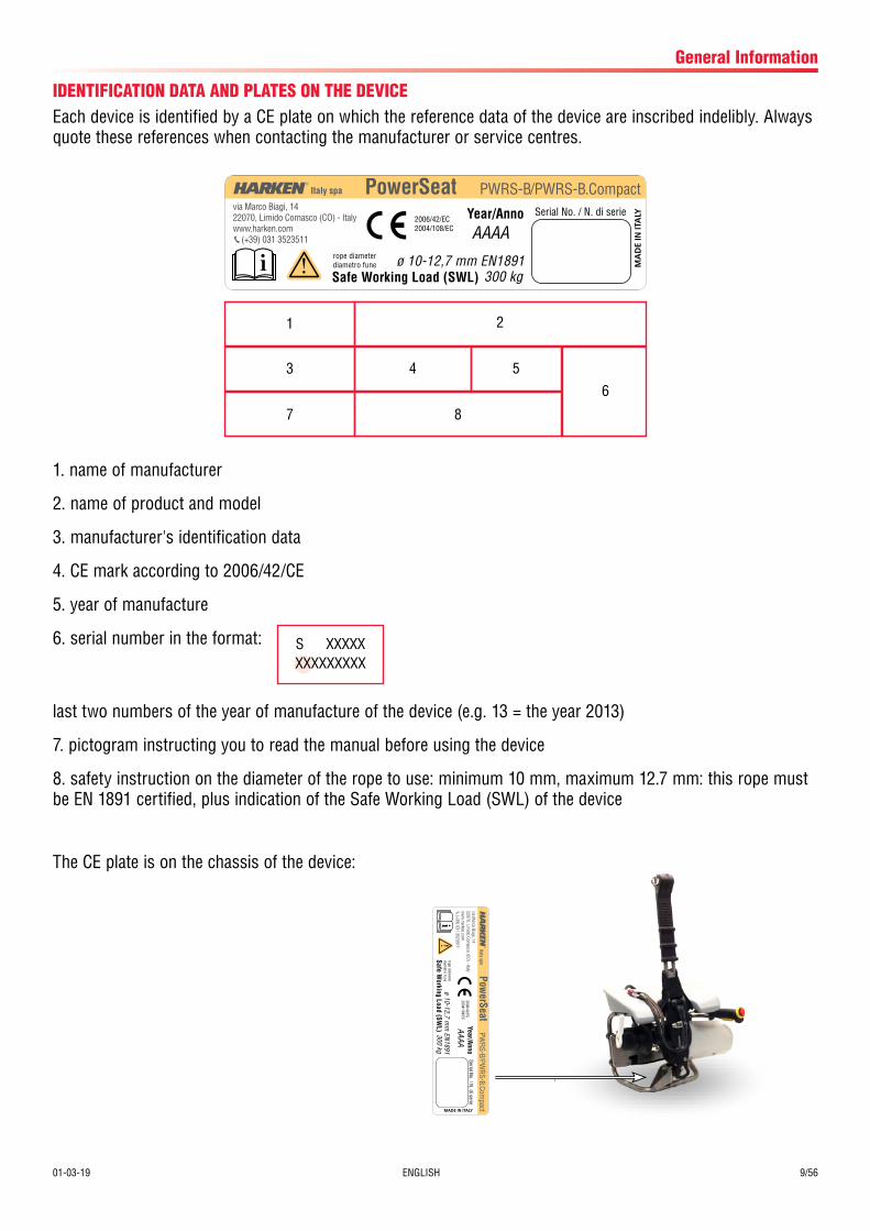
IDENTIFICATION DATA AND PLATES ON THE DEVICEEach device is identified by a CE plate on which the reference data of the device are inscribed indelibly. Always quote these references when contacting the manufacturer or service centres.
1. name of manufacturer
2. name of product and model
3. manufacturer's identification data
4. CE mark according to 2006/42/CE
5. year of manufacture
6. serial number in the format:
last two numbers of the year of manufacture of the device (e.g. 13 = the year 2013)
7. pictogram instructing you to read the manual before using the device
8. safety instruction on the diameter of the rope to use: minimum 10 mm, maximum 12.7 mm: this rope must be EN 1891 certified, plus indication of the Safe Working Load (SWL) of the device
The CE plate is on the chassis of the device:
i
PWRS-B/PWRS-B.CompactSerial No. / N. di serie
rope diameterdiametro fune
2006/42/EC2004/108/EC
Safe Working Load (SWL) 300 kg
via Marco Biagi, 1422070, Limido Comasco (CO) - Italywww.harken.com (+39) 031 3523511
PowerSeat
ø 10-12,7 mm EN1891
Year/AnnoAAAA
1 2
3 4 5
7 8
6
S XXXXXXXXXXXXXX
i
PWRS-B/PW
RS-B.Compact
Serial No. / N
. di serie
rope diameter
diametro fune
2006/42/EC2004/108/EC
Safe Working Load (SW
L)300 kg
via Marco Biagi, 14
22070, Limido Com
asco (CO) - Italyw
ww
.harken.com (+39) 031 3523511
PowerSeat
ø 10-12,7 mm
EN1891
Year/AnnoAAAA
10/56 ENGLISH 01-03-19
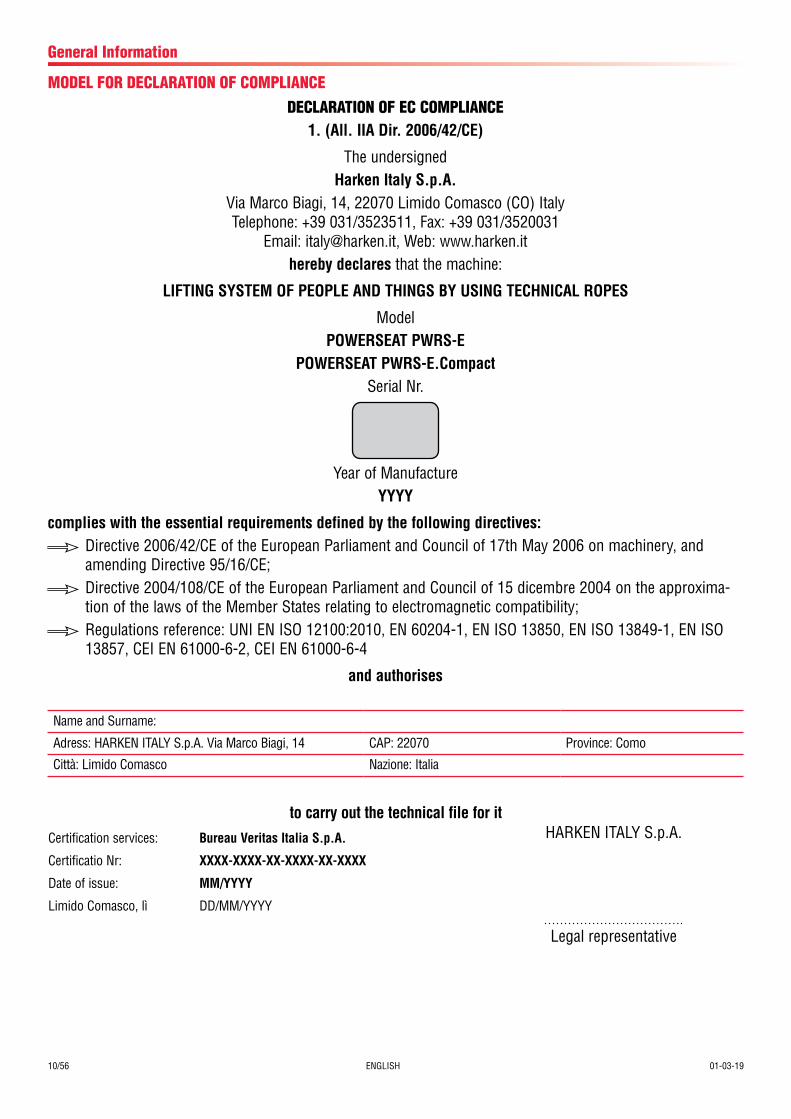
MODEL FOR DECLARATION OF COMPLIANCE
General Information
Year of ManufactureYYYY
complies with the essential requirements defined by the following directives:Directive 2006/42/CE of the European Parliament and Council of 17th May 2006 on machinery, and amending Directive 95/16/CE;Directive 2004/108/CE of the European Parliament and Council of 15 dicembre 2004 on the approxima-tion of the laws of the Member States relating to electromagnetic compatibility;Regulations reference: UNI EN ISO 12100:2010, EN 60204-1, EN ISO 13850, EN ISO 13849-1, EN ISO 13857, CEI EN 61000-6-2, CEI EN 61000-6-4
and authorises
DECLARATION OF EC COMPLIANCE1. (All. IIA Dir. 2006/42/CE)
The undersignedHarken Italy S.p.A.
Via Marco Biagi, 14, 22070 Limido Comasco (CO) Italy Telephone: +39 031/3523511, Fax: +39 031/3520031
Email: [email protected], Web: www.harken.ithereby declares that the machine:
LIFTING SYSTEM OF PEOPLE AND THINGS BY USING TECHNICAL ROPES
ModelPOWERSEAT PWRS-E
POWERSEAT PWRS-E.CompactSerial Nr.
Name and Surname:
Adress: HARKEN ITALY S.p.A. Via Marco Biagi, 14 CAP: 22070 Province: Como
Città: Limido Comasco Nazione: Italia
Certification services: Bureau Veritas Italia S.p.A.
Certificatio Nr: XXXX-XXXX-XX-XXXX-XX-XXXX
Date of issue: MM/YYYY
Limido Comasco, lì DD/MM/YYYY
HARKEN ITALY S.p.A.
Legal representative
to carry out the technical file for it

01-03-19 ENGLISH 11/56
General Information
The device has been manufactured in conformity with the TECHNICAL REGULATIONS listed below:STANDARD REFERENCES
Reference technical standardsUNI EN ISO 12100:2010 Safety of machinery -- General principles for design -- Risk assessment and risk reductionUNI EN ISO 13850:2015 Safety of machinery - Emergency stop system, functional aspectsUNI EN ISO 13857:2008 Safety of machinery -- Safety distances to prevent hazard zones being reached by upper and lower limbs
UNI EN 349:2008 Safety of machinery - Minimum gaps to avoid crushing of parts of the human bodyUNI EN 14118:2018 Safety of machinery - Prevention of unexpected start-upEN ISO 13849-1:2016 Safety of machinery – Safety-related parts of control systems – Part 1: General principles for designEN ISO 13849-2:2013 Safety of machinery – Safety-related parts of control systems – Part 2: ValidationUNI EN ISO 13732-1:2009 Ergonomics of the thermal environment - Methods for the assessment of human responses to contact with
surfaces - Part 1: Hot surfacesUNI EN 614-1:2009 Safety of machinery - Ergonomic design principles - Part 1: Terminology and general principlesUNI EN 614-2:2009 Specification and qualification of welding procedures for metallic materials - Welding procedure test - Part
2: Arc welding of aluminium and its alloysUNI EN 14120:2015 Safety of machinery - Guards - General requirements for the design and construction of fixed and movable
guardsUNI EN 1005-1:2009 Safety of machinery - Human physical performance - Part 1: Terms and definitionsUNI EN 1005-3:2009 Safety of machinery - Human physical performance - Part 3: Recommended force limits for machinery
operationUNI EN 1005-4:2009 Safety of machinery - Human physical performance - Part 4: Evaluation of working postures and move-
ments in relation to machineryUNI EN ISO 3746:2011 Acoustics - Determination of sound power levels and sound energy levels of noise sources using sound
pressure - Survey method using an enveloping measurement surface over a reflecting planeUNI EN ISO 11204:2010 Acoustics -- Noise emitted by machinery and equipment -- Determination of emission sound pressure lev-
els at a work station and at other specified positions applying accurate environmental correctionsUNI EN ISO 4871:2009 Acoustics - Declaration and verification of noise emission values of machinery and equipment
UNI EN ISO 7000:2014 Graphical symbols for use on equipment -- Registered symbols
CEI EN 61000-6-2:2016 Electromagnetic compatibility (EMC) - Part 6-2: Generic standards - Immunity for industrial environments
CEI EN 61000-6-4:2018 Electromagnetic compatibility (EMC) - Part 6-4: Generic standards - Immunity for industrial environments
CEI EN 61558-2-2:2007 Safety of power transformers, power supply units and similar - Part 2-2: Particular requirements for control transformers
CEI EN 60204-1:2016 Safety of machinery - Electrical equipment of machines. Part 1: General rules
CEI EN 60529:1997+A1(2000) +A2 (2014)
Degree of protection provided by enclosures (IP code)
UN 38.3 Transportation testing required for Lithium battery
IEC 62281:2016 Safety of primary and secondary Lithium cells and batteries during transport
IEC 82079-1:2012 Preparation of instruction - structuring, content and presentation
12/56 ENGLISH 01-03-19
General Information
TECHNICAL SUPPORT INFORMATIONThe PowerSeat is covered by a warranty, as laid down in the general conditions of sale. If during the warranty period the device proves defective or suffers breakages, as indicated in the warranty, the manufacturer, after checking the device, will repair or replace the defective components. You are reminded that modifications carried out by the user, without explicit written authorisation from the manufacturer, will invalidate the warranty and relieve the manufacturer of any responsibility for damage caused by the defective product. The same considerations apply when spare parts that are not original or different from those explicitly indicated by the manufacturer as “safety devices” are used. For all these reasons we advise customers to contact Harken Technical Support.
IC CERTIFICATIONThis Class A digital apparatus meets all requirements of the Canadian Interference-Causing Equipment Regulations.
FCC VERIFICATIONThis device complies with Part 15 of the FCC Rules. Operation is subject to the following two conditions:
1) this device may not cause harmful interference
2) this device must accept any interference received, including interference that may cause undesired operation
Note!This equipment has been tested and found to comply with the limits for a Class A digital device, pursuant to Part 15 of the FCC rules. These limits are designed to provide reasonable protection against harmful interference in a residential installation. This equipment generates, uses and can radiate radio frequency energy and, if not installed and used in accordance with the instructions, may cause harmful interference to radio communications. However, there is no guarantee that the interference will not occur in a particular installation. If this equipment does cause harmful interference to radio or television reception, which can be determined by turning the equipment off and on, the user is encouraged to try to correct the interference by one or more of the following measures:- Reorient or relocate the receiving antenna.- Increase the separation between the equipment and receiver.- Connect the equipment into an outlet on a circuit different from that of the receiver.- Consult the dealer or an experienced radio/TV technician for help.
01-03-19 ENGLISH 13/56
Safety Precaution
GENERAL ADVICE
Use of the PowerSeat is restricted to qualified operators who are certified for temporary work at height with the use of access and positioning systems using ropes according to the current regulations of the Nation in which the device is used.
Harken is not responsible for damage caused by the PowerSeat to people, animals or property in the case of:
- use of the PowerSeat by operators without proper certification
- improper use of the PowerSeat
- lack of proper maintenance, as indicated in the Maintenance chapter of this Manual
- unauthorised modifications or changes
- use of spare parts that are not original or specific for the model
- total or partial failure to observe the instructions
- usage contrary to specific national regulations
INTENDED USEThe PowerSeat is designed to help qualified operators ascend a rope using the engine and descend using a passive manual device. The PowerSeat is not safety equipment and is not a Personal Protective Equipment. It must always be used in combination with a secondary rope to which is connected the fall arrest device fixed to the operator’s harness by a cord with an energy absorber, and must satisfy the requirements of EN 363 on individual systems for the protection against falling from heights.
In order to use the PowerSeat a risk analysis, and rescue plan must have been drawn up, as required by current regulations of the nation where the device is used on temporary work at height and the use of access and positioning systems using ropes.
The following guidelines must also be considered:
- ISO 22846: Personal equipment for protection against falls (Part 1/Part 2)
- IRATA: International Code of Practice.
- C(HSW)R: The Construction (Health, Safety and Welfare) Regulations.
- LOLER: The Lifting Operations and Lifting Equipment Regulations.
- MHSWR: The Management of Health and Safety at Work Regulations.
- PUWER: The Provision and Use of Work Equipment Regulations
This list is not complete and it is the responsibility of the qualified operator to be aware of current regulations in his country on temporary work at height and the use of access and positioning systems using ropes or other regulations relating to his specific sector of work.
WARNING!read the instructions in this manual attentively and carefully follow the indications it contains before using the PowerSeat
14/56 ENGLISH 01-03-19
Safety Precaution
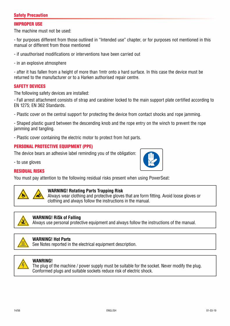
IMPROPER USEThe machine must not be used:
- for purposes different from those outlined in “Intended use” chapter, or for purposes not mentioned in this manual or different from those mentioned
- if unauthorised modifications or interventions have been carried out
- in an explosive atmosphere
- after it has fallen from a height of more than 1mtr onto a hard surface. In this case the device must be returned to the manufacturer or to a Harken authorised repair centre.
SAFETY DEVICESThe following safety devices are installed:- Fall arrest attachment consists of strap and carabiner locked to the main support plate certified according to EN 1275; EN 362 Standards.
- Plastic cover on the central support for protecting the device from contact shocks and rope jamming.
- Shaped plastic guard between the descending knob and the rope entry on the winch to prevent the rope jamming and tangling.
- Plastic cover containing the electric motor to protect from hot parts.
PERSONAL PROTECTIVE EQUIPMENT (PPE)The device bears an adhesive label reminding you of the obligation:
- to use gloves
RESIDUAL RISKSYou must pay attention to the following residual risks present when using PowerSeat:
WARNING! RiSk of FallingAlways use personal protective equipment and always follow the instructions of the manual.
WARNING! Rotating Parts Trapping RiskAlways wear clothing and protective gloves that are form fitting. Avoid loose gloves or clothing and always follow the instructions in the manual.
WARNING! Hot PartsSee Notes reported in the electrical equipment description.
WANRING!The plug of the machine / power supply must be suitable for the socket. Never modify the plug.Conformed plugs and suitable sockets reduce risk of electric shock.

01-03-19 ENGLISH 15/56
Safety Precaution
WARNING!Do not use the device with faulty switches.Devices or control systems with faulty switch are dangerous and require maintanance.
WARNING!Do not remove the motor carter.
16/56 ENGLISH 01-03-19
Information on the power system
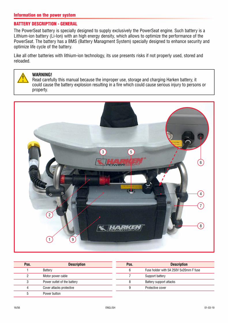
BATTERY DESCRIPTION - GENERALThe PowerSeat battery is specially designed to supply exclusively the PowerSeat engine. Such battery is a Lithium-ion battery (Li-Ion) with an high energy density, which allows to optimize the performance of the PowerSeat. The battery has a BMS (Battery Managment System) specially designed to enhance security and optimize life cycle of the battery.
Like all other batteries with lithium-ion technology, its use presents risks if not properly used, stored and reloaded.
WARNING!Read carefully this manual because the improper use, storage and charging Harken battery, it could cause the battery explosion resulting in a fire which could cause serious injury to persons or property.
Pos. Description1 Battery
2 Motor power cable
3 Power outlet of the battery
4 Cover attacks protective
5 Power button
Pos. Description6 Fuse holder with 5A 250V 5x20mm F fuse
7 Support battery
8 Battery support attacks
9 Protective cover
9
8
7
1
2
4
3 5
6

01-03-19 ENGLISH 17/56
BATTERY DESCRIPTION - TECHNICAL DATA
Type Li-Ion
Cells Panasonic
Nominal Voltage min 38,4 Vac / max 50,4 V
Nominal Capacity 9 Ah
Nominal Energy 388,8 Wh
Rated charging current 2 A
Current short-circuit 100 A
Interruption time for the short-circuit 100 ms
Temperature range in download -10 °C / +50 °C
Temperature range in upload 0 °C / +40 °C
Dimensions (WxLxH) 240x144x93 mm
Weight 3,6 kg
Thermal Protection (charging/discharging) electric control
Degree of Protection IP54
Operating ambient temperature -10° C / +50° C
Storage Temperature Range +5 °C / +30 °C
Work environment internal and external use
Information on the power system
WARNING!Do not use batteries of PowerSeat to power other electrical products.
WARNING!Do not disassemble or modify the battery.
WARNING!An old battery, or a completely discharged battery, or a battery that has less than 80% of the initialcapacity, or a battery that present the poor performance should be taken out of service and replacedwith a new battery.
SAFETY INFORMATION
BATTERY DESCRIPTION - INTERFACE LIGHTThe power button turns on and off the battery. Integrated into the power button there are three LEDs. Turning on the battery, the LEDs displays the battery state of charge:
If during the battery discharge, the remaining charge drops below a predetermined threshold there will be a commutation of the state of the LEDs.
LED DescriptionGreen State of charge between 100% and 50%
Green/Red State of charge between 49% and 20%
Red State of charge between 19% and 1%
18/56 ENGLISH 01-03-19
BATTERY USAGE
Battery performance depends on the temperature of the batteries.
The use of the battery at low temperatures, affect the performance of the PowerSeat and the ascent rate will be limited. The return of the battery to temperatures in the range of use allows you to get the expected performance.
Information on the power system
WARNING!Use the battery according to the environmental specifications! Improper use can damage electronic circuits.
WARNING!Exposure of batteries to a temperature greater than 60°C can cause irreversible damage to the battery and cause a fire.
NOTE!Use the battery at a temperature between -10°C/+ 50°C.
NOTE!When you purchase the battery, perform a complete charge cycle to preserve its useful life.
NOTE!In the standard service conditions, the battery lifetime is at least 500 complete charging cycles and approximately 5 years. The effective duration depends on how the battery has been used, on the usage temperature, on the storage conditions and on the recharge frequency. To evaluate the battery condition, contact an authorized Harken Service Center.
NOTE!The battery automatically shuts off after 5 hours of non-use. To turn the battery off, push the power button.
WARNING!Put immediately the battery out of service if there are any visible damage to the outer casing or to the cables or to the connectors or if it has been dropped, even if damage is not visible.
WARNING!Put immediately out of service and place in an isolated area, outside and away from combustibleor flammable substances, the battery that emanates a strange smell, is too hot, or presents abnormalities.
WARNING!Do not short-circuit the battery, as this could cause serious damage to people and property.
WARNING!Do not immerse the battery in water.
01-03-19 ENGLISH 19/56
Information on the power system
BATTERY CHARGINGTo recharge the battery, use a charger with the following specifications:
To recharge the battery, follow the procedure:
1. turn off the battery
2. disconnect the battery from the PowerSeat
3. connect the charger to the electricity
4. connect the battery off to the charger
5. turn on the battery through the power button
During the charging, the LED that represent the state of charge, is flashing. Upon reaching the full charge, the green LED is fixed. Cyclically, the green LED may be turned off for a while and this is due to periodic inspection carried out by the BMS, the battery charge and temperature.
During the charging, the LED on the charger is red. Once you reach the full charge of the battery, the LED on the charger turns green. When the battery is fully charged, turn off the battery through the power button and then disconnect the charger from the power supply before removing the battery.
To recharge a completely discharged battery is needed 4h 30'. The charging process is linear.
The battery gradually loses its charge up to total exhaustion. If this happens, the battery may no longer be able to operate even when connected to the charger. To avoid this situation, you must fully charge the battery at least once every 4 months, even if they are not used in this time frame.
WARNING!Before connecting the charger to the power supply, make sure that the power supply voltage is within the range specified in the specifications of the charger.
In the case of short-circuit of the battery, the power interruption occurs through the breaking of the series of the two components mosfet and Hall effect current sensor. The value of the short-circuit operation is 100A, the interruption time is 100 ms. Following the short-circuit, LEDs will be turned off.
Chargers for batteries 12 celle Li-Ion
Mains voltage 110-120 Vac / 220-240 Vac
Output Voltage 50,4 Vdc
Rated charging current 2 A
Mains frequency 50-60 Hz
NOTE!The performance shown were obtained with a battery charger having the specifications listed above.
NOTE!In case of short circuit of the battery, this should be sent to Harken for maintenance, subject toauthorization by Harken.
NOTE!Switch off the battery after use.
20/56 ENGLISH 01-03-19
Information on the power system
WARNING!Do not store the battery turned on.
STORE AND SHIPPING
WARNING!Do not store the battery connected to PowerSeat or connected to the charger.
NOTE!Store the battery charged to 100%. Storing an empty battery or a battery with a low charge level can damage irreversibly the battery.
NOTE!Recharge the battery at least once every 4 months if stored for a long period of time.
WARNING!Disconnect the battery from the charger when it finished the charging.
WARNING!Disconnect the charger from the network when it finished the charging.
WARNING!Recharge the battery only when they have reached room temperature.
WARNING!Recharge the battery in a place indoors, dry, safe and not exposed to direct sunlight, away from fuel or other flammable substances, as in the case there is a serious fault in the charging of the battery, such event could cause the explosion of the battery and consequently a fire.
WARNING!Use only the charger supplied by Harken to recharge the battery.
NOTE!Recharge the battery after each use and at least every four months to prevent damage to the batteryand preserve its useful life.
WARNING!Charge the battery at a temperature between 0°C / +40°C.
In case the temperature exceeds of + 40°C, the charge is interrupted by the BMS and the LED state of charge (on the battery) becomes fixed. The BMS cyclically controls the temperature of the battery and if it detects a temperature between 0°C / +40°C, the charging process will start again.

01-03-19 ENGLISH 21/56
WARNING!Do not ship a defective battery.
WARNING!Store the battery in a place indoors, dry, safe and not exposed to direct sunlight, away from fuel or other flammable substances, at a temperature between 0°C/+40°C. The storage at a higher temperature may alter the performance of the batteries reducing their expected life. The storage at a temperature greater than 60°C can cause irreversible damage to the battery and cause a fire.
WARNING!The lithium-ion batteries Harken are classified as dangerous goods according to UN3480 - Class 9 and must be sent as specified in such legislation.
Information on the power system
22/56 ENGLISH 01-03-19
PowerSeat PWRS-B
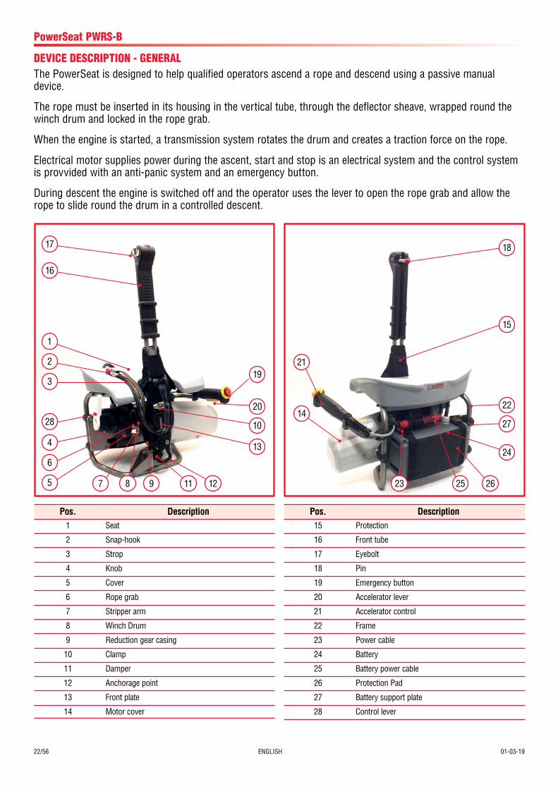
DEVICE DESCRIPTION - GENERALThe PowerSeat is designed to help qualified operators ascend a rope and descend using a passive manual device.
The rope must be inserted in its housing in the vertical tube, through the deflector sheave, wrapped round the winch drum and locked in the rope grab.
When the engine is started, a transmission system rotates the drum and creates a traction force on the rope.
Electrical motor supplies power during the ascent, start and stop is an electrical system and the control system is provvided with an anti-panic system and an emergency button.
During descent the engine is switched off and the operator uses the lever to open the rope grab and allow the rope to slide round the drum in a controlled descent.
Pos. Description1 Seat
2 Snap-hook
3 Strop
4 Knob
5 Cover
6 Rope grab
7 Stripper arm
8 Winch Drum
9 Reduction gear casing
10 Clamp
11 Damper
12 Anchorage point
13 Front plate
14 Motor cover
Pos. Description15 Protection
16 Front tube
17 Eyebolt
18 Pin
19 Emergency button
20 Accelerator lever
21 Accelerator control
22 Frame
23 Power cable
24 Battery
25 Battery power cable
26 Protection Pad
27 Battery support plate
28 Control lever
15
18
22
27
24
21
14
262523
17
16
7 8 9 11 12
20
19
10
13
1
2
3
28
4
6
5
01-03-19 ENGLISH 23/56
PowerSeat PWRS-B
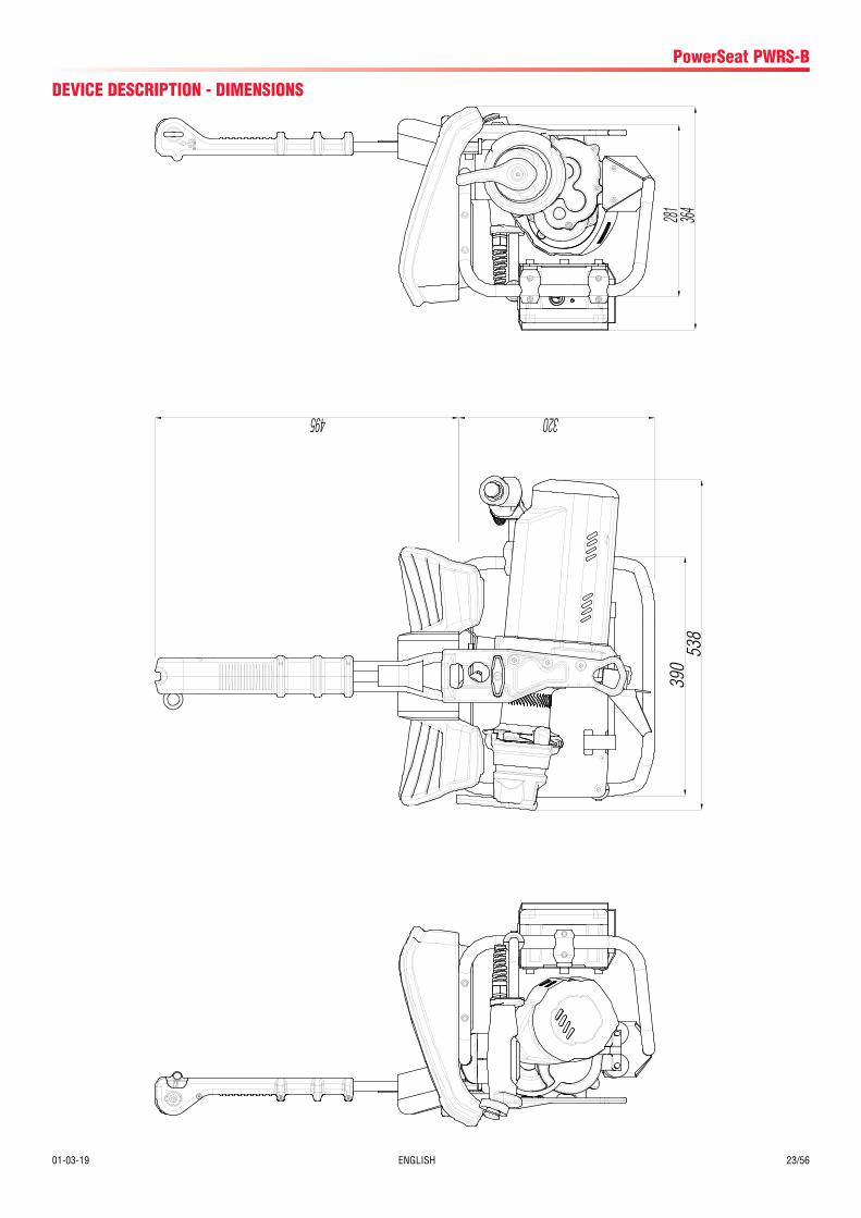
DEVICE DESCRIPTION - DIMENSIONS
390
364281
495 320
538
24/56 ENGLISH 01-03-19
PowerSeat PWRS-B
DEVICE DESCRIPTION - VIBRATIONSVibration values measured are below the limits set by the reference standards:
Hand-arm <2,5 (A(8)m/s), Whole body <0,5 (A(8)m/s).
DEVICE DESCRIPTION - NOISE EMISSIONThe values of the measured noise emissions are below the limits allowed under the applicable standards - ISO 3746:
- Average surface acoustic pressure level weighted A:
(LpfA,d (medio)) < 80 dB(A)
- Acoustic power level weighted A (LWA) < 90 dB(A)
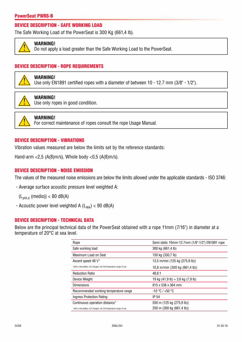
DEVICE DESCRIPTION - SAFE WORKING LOADThe Safe Working Load of the PowerSeat is 300 Kg (661,4 lb).
WARNING!Do not apply a load greater than the Safe Working Load to the PowerSeat.
DEVICE DESCRIPTION - ROPE REQUIREMENTS
WARNING!Use only EN1891 certified ropes with a diameter of between 10 - 12.7 mm (3/8" - 1/2").
WARNING!Use only ropes in good condition.
WARNING!For correct maintenance of ropes consult the rope Usage Manual.
Rope Semi static 10mm-12.7mm (1/8"-1/2") EN1891 rope
Safe working load 300 kg (661,4 lb)
Maximum Load on Seat 150 kg (330,7 lb)
Ascent speed 48 V**with a new battery, full charged, into the temperature range of use
13,5 m/min (125 kg (275,9 lb))
10,8 m/min (300 kg (661,4 lb))
Reduction Ratio 48,6:1
Device Weight 19 kg (41,9 lb) + 3,6 kg (7,9 lb)
Dimensions 815 x 538 x 364 mm
Recommended working temperature range -10 °C / +50 °C
Ingress Protection Rating IP 54
Continuous operation distance**with a new battery, full charged, into the temperature range of use
550 m (125 kg (275,9 lb))250 m (300 kg (661,4 lb))
DEVICE DESCRIPTION - TECHNICAL DATABelow are the principal technical data of the PowerSeat obtained with a rope 11mm (7/16") in diameter at a temperature of 20°C at sea level.
01-03-19 ENGLISH 25/5625 ITALIANO 30/01/14
PowerSeat PWRS-B
DEVICE DESCRIPTION - MOTOR
Motor Brushless electric
Nominal Voltage 48 Vdc
Net Power 0,8 kW
Thermal Protection Activation temp. 100°C (212°F)
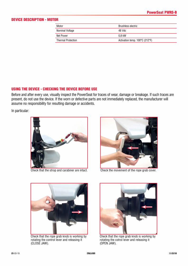
USING THE DEVICE - CHECKING THE DEVICE BEFORE USEBefore and after every use, visually inspect the PowerSeat for traces of wear, damage or breakage. If such traces are present, do not use the device. If the worn or defective parts are not immediately replaced, the manufacturer will assume no responsibility for resulting damage or accidents.
In particular:
Check that the strop and carabiner are intact. Check the movement of the rope grab cover.
Check that the rope grab knob is working by rotating the cotrol lever and releasing it (OPEN JAW).
Check that the rope grab knob is working by rotating the control lever and releasing it (CLOSE JAW).
26/56 ENGLISH 01-03-1930/01/14 ITALIANO 26
PowerSeat PWRS-B
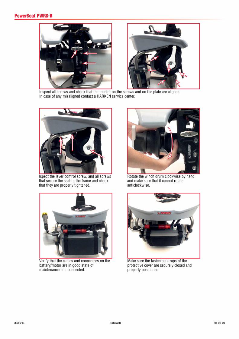
Inspect all screws and check that the marker on the screws and on the plate are aligned.In case of any misaligned contact a HARKEN service center.
Rotate the winch drum clockwise by hand and make sure that it cannot rotate anticlockwise.
Ispect the lever control screw, and all screws that secure the seat to the frame and check that they are properly tightened.
Verify that the cables and connectors on thebattery/motor are in good state ofmaintenance and connected.
Make sure the fastening straps of theprotective cover are securely closed andproperly positioned.
01-03-19 ENGLISH 27/56
PowerSeat PWRS-B
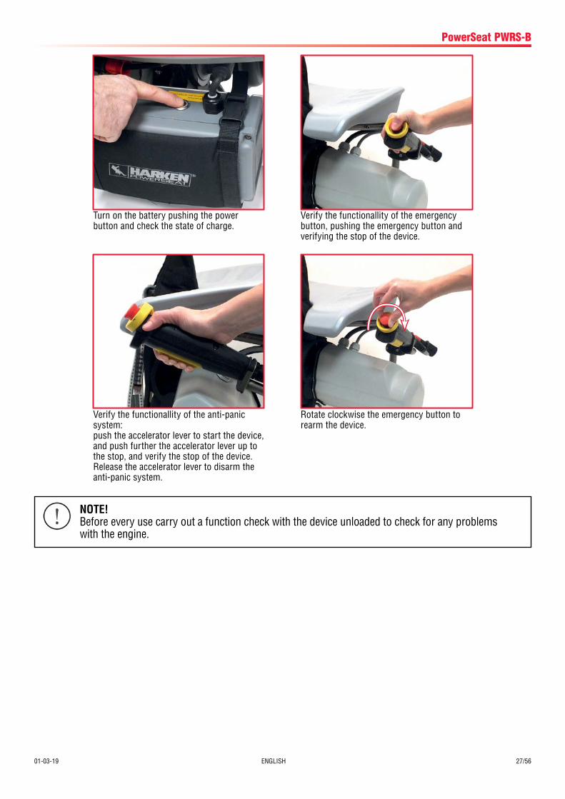
Verify the functionallity of the anti-panic system:push the accelerator lever to start the device, and push further the accelerator lever up to the stop, and verify the stop of the device.Release the accelerator lever to disarm the anti-panic system.
NOTE!Before every use carry out a function check with the device unloaded to check for any problems with the engine.
Verify the functionallity of the emergency button, pushing the emergency button and verifying the stop of the device.
Rotate clockwise the emergency button to rearm the device.
Turn on the battery pushing the power button and check the state of charge.
28/56 ENGLISH 01-03-19
PowerSeat PWRS-B
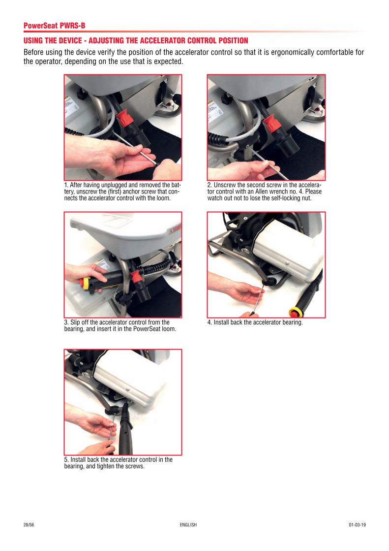
USING THE DEVICE - ADJUSTING THE ACCELERATOR CONTROL POSITION
3. Slip off the accelerator control from the bearing, and insert it in the PowerSeat loom.
5. Install back the accelerator control in the bearing, and tighten the screws.
4. Install back the accelerator bearing.
1. After having unplugged and removed the bat-tery, unscrew the (first) anchor screw that con-nects the accelerator control with the loom.
2. Unscrew the second screw in the accelera-tor control with an Allen wrench no. 4. Please watch out not to lose the self-locking nut.
Before using the device verify the position of the accelerator control so that it is ergonomically comfortable for the operator, depending on the use that is expected.
01-03-19 ENGLISH 29/56
PowerSeat PWRS-B
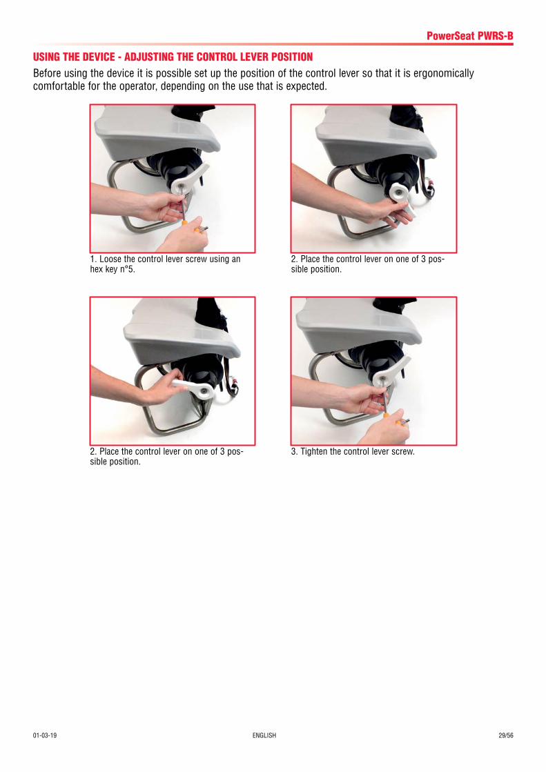
USING THE DEVICE - ADJUSTING THE CONTROL LEVER POSITIONBefore using the device it is possible set up the position of the control lever so that it is ergonomically comfortable for the operator, depending on the use that is expected.
1. Loose the control lever screw using an hex key n°5.
2. Place the control lever on one of 3 pos-sible position.
3. Tighten the control lever screw.2. Place the control lever on one of 3 pos-sible position.
30/56 ENGLISH 01-03-19
PowerSeat PWRS-B
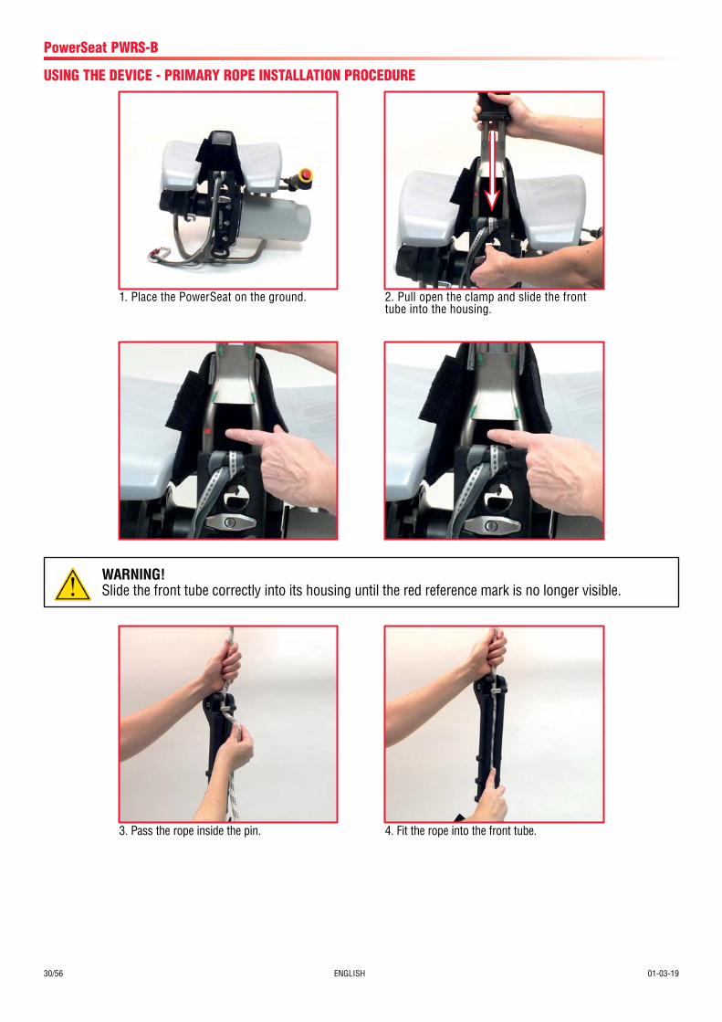
3. Pass the rope inside the pin. 4. Fit the rope into the front tube.
WARNING!Slide the front tube correctly into its housing until the red reference mark is no longer visible.
1. Place the PowerSeat on the ground.
USING THE DEVICE - PRIMARY ROPE INSTALLATION PROCEDURE
2. Pull open the clamp and slide the front tube into the housing.
01-03-19 ENGLISH 31/56
PowerSeat PWRS-B
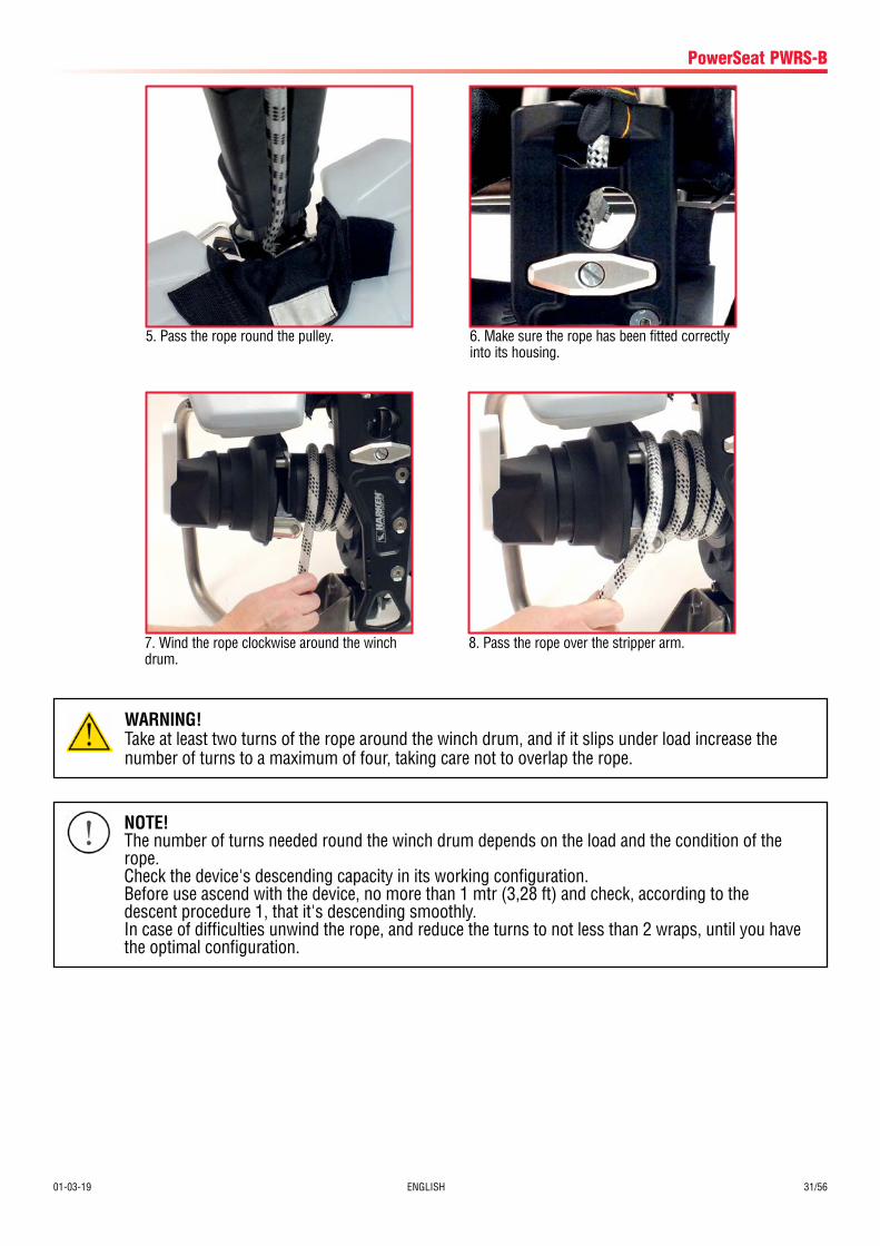
5. Pass the rope round the pulley. 6. Make sure the rope has been fitted correctly into its housing.
7. Wind the rope clockwise around the winch drum.
8. Pass the rope over the stripper arm.
WARNING!Take at least two turns of the rope around the winch drum, and if it slips under load increase the number of turns to a maximum of four, taking care not to overlap the rope.
NOTE!The number of turns needed round the winch drum depends on the load and the condition of the rope.Check the device's descending capacity in its working configuration.Before use ascend with the device, no more than 1 mtr (3,28 ft) and check, according to the descent procedure 1, that it's descending smoothly.In case of difficulties unwind the rope, and reduce the turns to not less than 2 wraps, until you have the optimal configuration.
32/56 ENGLISH 01-03-19
PowerSeat PWRS-B
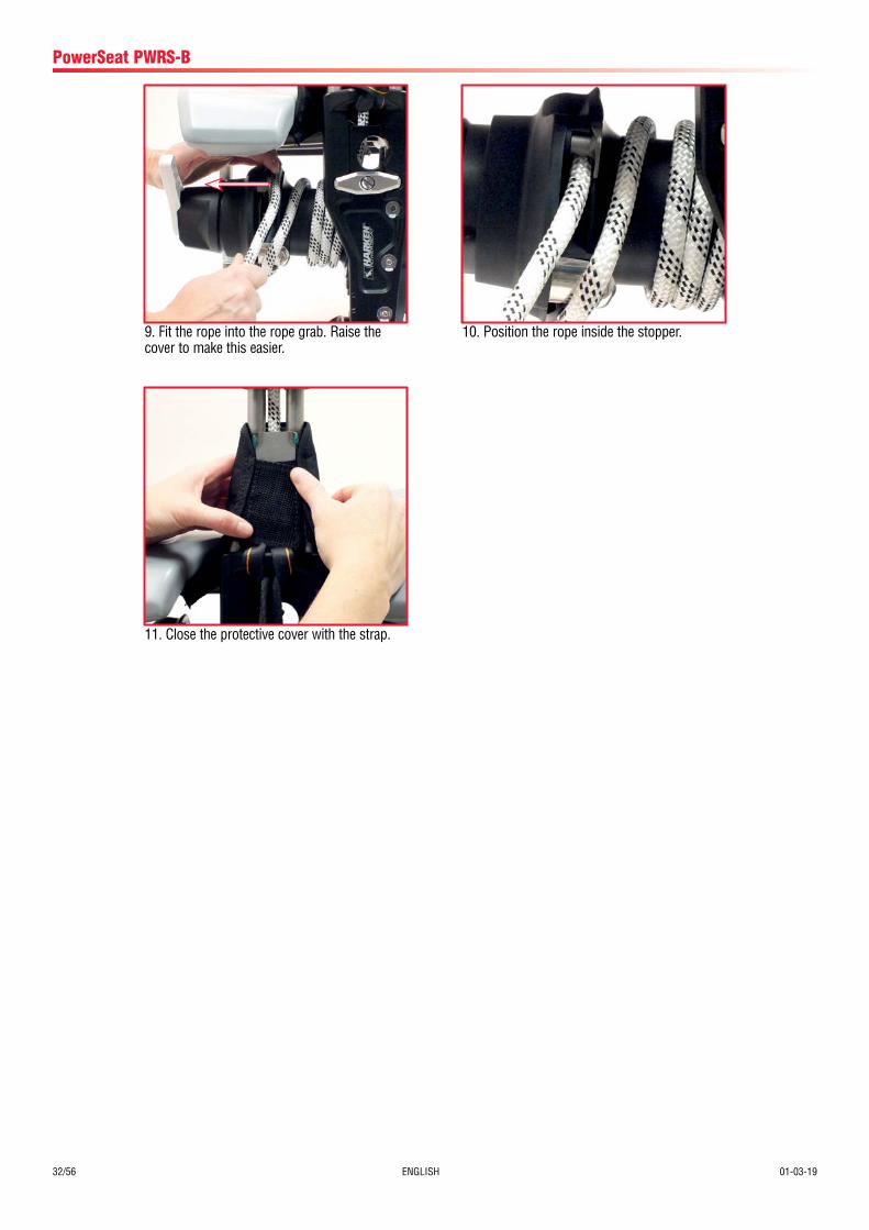
9. Fit the rope into the rope grab. Raise the cover to make this easier.
10. Position the rope inside the stopper.
11. Close the protective cover with the strap.
01-03-19 ENGLISH 33/56
PowerSeat PWRS-B
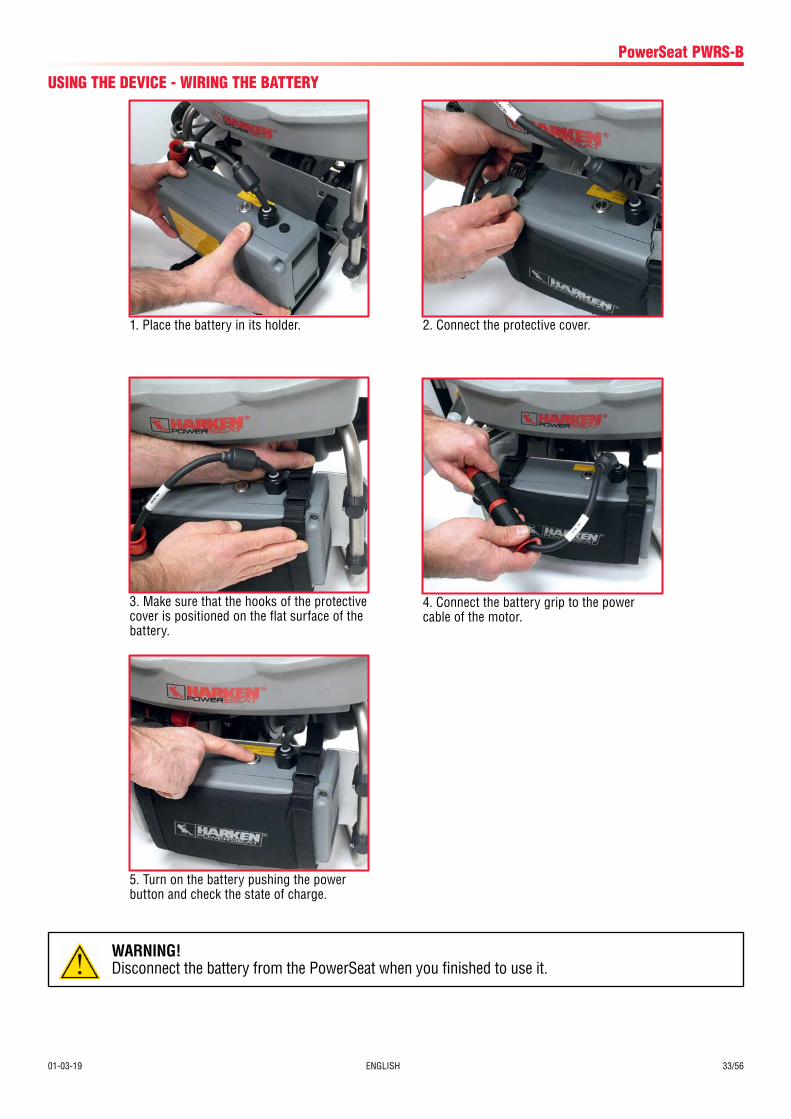
USING THE DEVICE - WIRING THE BATTERY
WARNING!Disconnect the battery from the PowerSeat when you finished to use it.
1. Place the battery in its holder. 2. Connect the protective cover.
4. Connect the battery grip to the power cable of the motor.
3. Make sure that the hooks of the protective cover is positioned on the flat surface of the battery.
5. Turn on the battery pushing the power button and check the state of charge.
34/56 ENGLISH 01-03-19
PowerSeat PWRS-B
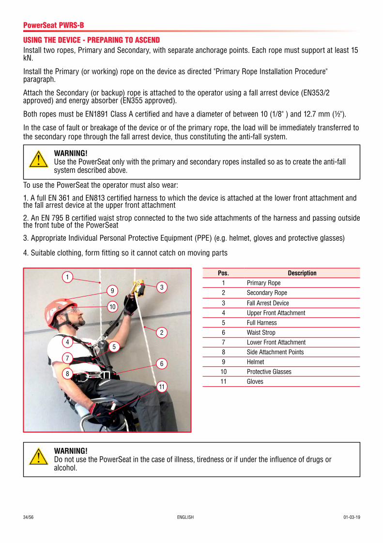
USING THE DEVICE - PREPARING TO ASCENDInstall two ropes, Primary and Secondary, with separate anchorage points. Each rope must support at least 15 kN.
Install the Primary (or working) rope on the device as directed "Primary Rope Installation Procedure" paragraph.
Attach the Secondary (or backup) rope is attached to the operator using a fall arrest device (EN353/2 approved) and energy absorber (EN355 approved).
Both ropes must be EN1891 Class A certified and have a diameter of between 10 (1/8" ) and 12.7 mm (1/2").
In the case of fault or breakage of the device or of the primary rope, the load will be immediately transferred to the secondary rope through the fall arrest device, thus constituting the anti-fall system.
To use the PowerSeat the operator must also wear:
1. A full EN 361 and EN813 certified harness to which the device is attached at the lower front attachment and the fall arrest device at the upper front attachment
2. An EN 795 B certified waist strop connected to the two side attachments of the harness and passing outside the front tube of the PowerSeat
3. Appropriate Individual Personal Protective Equipment (PPE) (e.g. helmet, gloves and protective glasses)
4. Suitable clothing, form fitting so it cannot catch on moving parts
Pos. Description1 Primary Rope2 Secondary Rope
3 Fall Arrest Device4 Upper Front Attachment5 Full Harness6 Waist Strop7 Lower Front Attachment8 Side Attachment Points9 Helmet10 Protective Glasses11 Gloves
11
6
5
1
9
24
7
8
3
10
WARNING!Do not use the PowerSeat in the case of illness, tiredness or if under the influence of drugs or alcohol.
WARNING!Use the PowerSeat only with the primary and secondary ropes installed so as to create the anti-fall system described above.
01-03-19 ENGLISH 35/56
PowerSeat PWRS-B
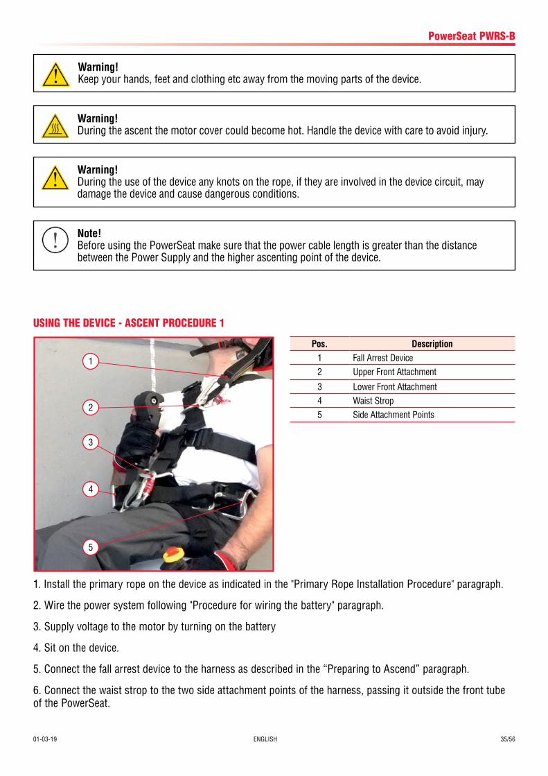
USING THE DEVICE - ASCENT PROCEDURE 1
Pos. Description1 Fall Arrest Device2 Upper Front Attachment
3 Lower Front Attachment4 Waist Strop5 Side Attachment Points
1
2
4
5
3
1. Install the primary rope on the device as indicated in the "Primary Rope Installation Procedure" paragraph.
2. Wire the power system following "Procedure for wiring the battery" paragraph.
3. Supply voltage to the motor by turning on the battery
4. Sit on the device.
5. Connect the fall arrest device to the harness as described in the “Preparing to Ascend” paragraph.
6. Connect the waist strop to the two side attachment points of the harness, passing it outside the front tube of the PowerSeat.
Warning!During the use of the device any knots on the rope, if they are involved in the device circuit, may damage the device and cause dangerous conditions.
Warning!During the ascent the motor cover could become hot. Handle the device with care to avoid injury.
Warning!Keep your hands, feet and clothing etc away from the moving parts of the device.
Note!Before using the PowerSeat make sure that the power cable length is greater than the distance between the Power Supply and the higher ascenting point of the device.
36/56 ENGLISH 01-03-19
PowerSeat PWRS-B
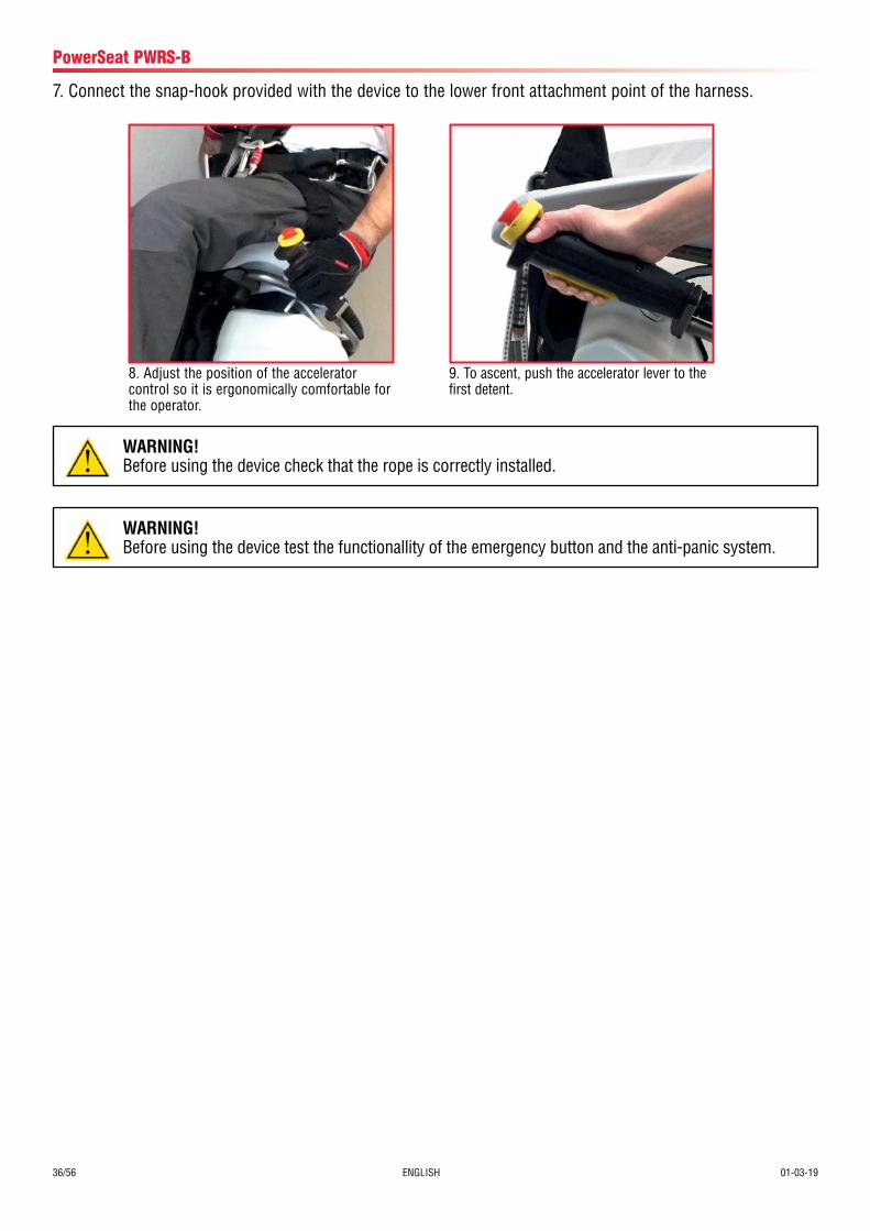
8. Adjust the position of the accelerator control so it is ergonomically comfortable for the operator.
9. To ascent, push the accelerator lever to the first detent.
WARNING!Before using the device check that the rope is correctly installed.
WARNING!Before using the device test the functionallity of the emergency button and the anti-panic system.
7. Connect the snap-hook provided with the device to the lower front attachment point of the harness.
01-03-19 ENGLISH 37/56
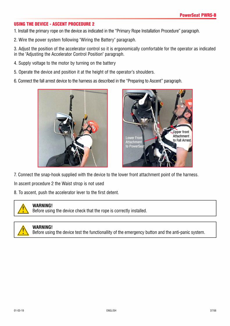
USING THE DEVICE - ASCENT PROCEDURE 21. Install the primary rope on the device as indicated in the “Primary Rope Installation Procedure” paragraph.
2. Wire the power system following "Wiring the Battery" paragraph.
3. Adjust the position of the accelerator control so it is ergonomically comfortable for the operator as indicated in the "Adjusting the Accelerator Control Position" paragraph.
4. Supply voltage to the motor by turning on the battery
5. Operate the device and position it at the height of the operator’s shoulders.
6. Connect the fall arrest device to the harness as described in the “Preparing to Ascent” paragraph.
PowerSeat PWRS-B
7. Connect the snap-hook supplied with the device to the lower front attachment point of the harness.
In ascent procedure 2 the Waist strop is not used
8. To ascent, push the accelerator lever to the first detent.
Upper frontAttachment to Fall Arrest
Lower Front Attachment to PowerSeat
WARNING!Before using the device check that the rope is correctly installed.
WARNING!Before using the device test the functionallity of the emergency button and the anti-panic system.
38/56 ENGLISH 01-03-19
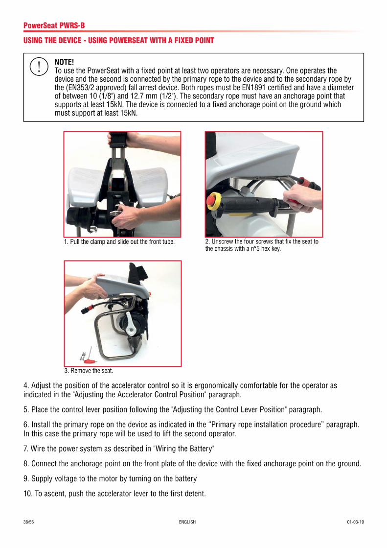
1. Pull the clamp and slide out the front tube. 2. Unscrew the four screws that fix the seat to the chassis with a n°5 hex key.
PowerSeat PWRS-B
4. Adjust the position of the accelerator control so it is ergonomically comfortable for the operator as indicated in the "Adjusting the Accelerator Control Position" paragraph.
5. Place the control lever position following the "Adjusting the Control Lever Position" paragraph.
6. Install the primary rope on the device as indicated in the “Primary rope installation procedure” paragraph. In this case the primary rope will be used to lift the second operator.
7. Wire the power system as described in "Wiring the Battery"
8. Connect the anchorage point on the front plate of the device with the fixed anchorage point on the ground.
9. Supply voltage to the motor by turning on the battery
10. To ascent, push the accelerator lever to the first detent.
3. Remove the seat.
USING THE DEVICE - USING POWERSEAT WITH A FIXED POINT
NOTE!To use the PowerSeat with a fixed point at least two operators are necessary. One operates the device and the second is connected by the primary rope to the device and to the secondary rope by the (EN353/2 approved) fall arrest device. Both ropes must be EN1891 certified and have a diameter of between 10 (1/8") and 12.7 mm (1/2"). The secondary rope must have an anchorage point that supports at least 15kN. The device is connected to a fixed anchorage point on the ground which must support at least 15kN.
01-03-19 ENGLISH 39/56
PowerSeat PWRS-B
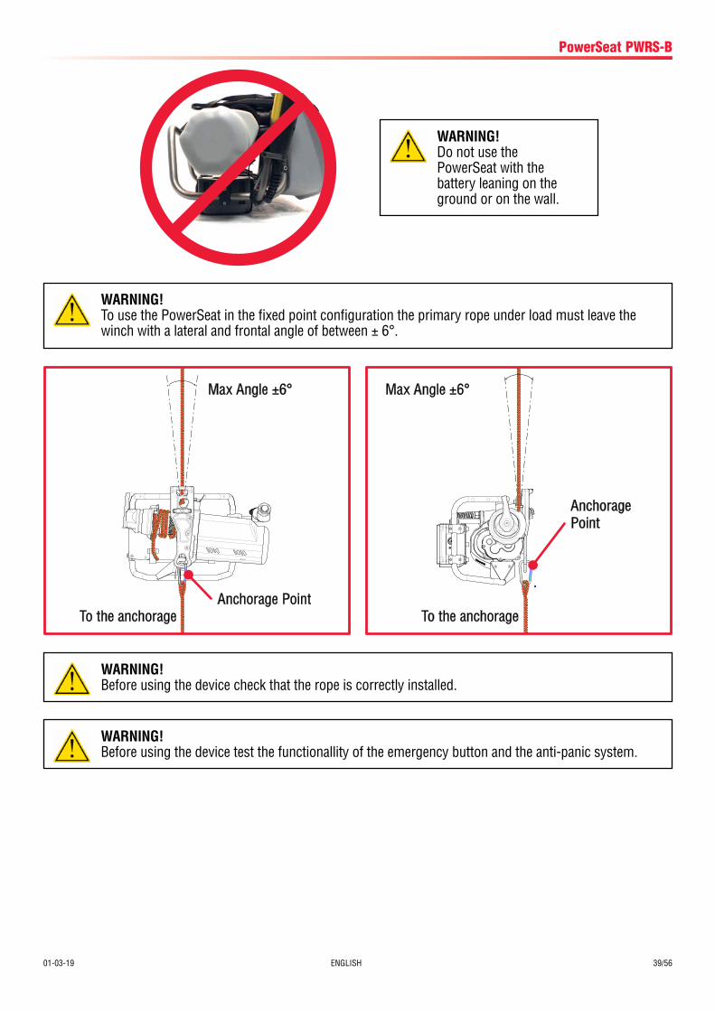
Max Angle ±6°
To the anchorageAnchorage Point
Max Angle ±6°
To the anchorage
Anchorage Point
WARNING!Before using the device test the functionallity of the emergency button and the anti-panic system.
WARNING!Before using the device check that the rope is correctly installed.
WARNING!To use the PowerSeat in the fixed point configuration the primary rope under load must leave the winch with a lateral and frontal angle of between ± 6°.
WARNING!Do not use the PowerSeat with the battery leaning on the ground or on the wall.
40/56 ENGLISH 01-03-19
USING THE DEVICE - DESCENT PROCEDURE 1
PowerSeat PWRS-B
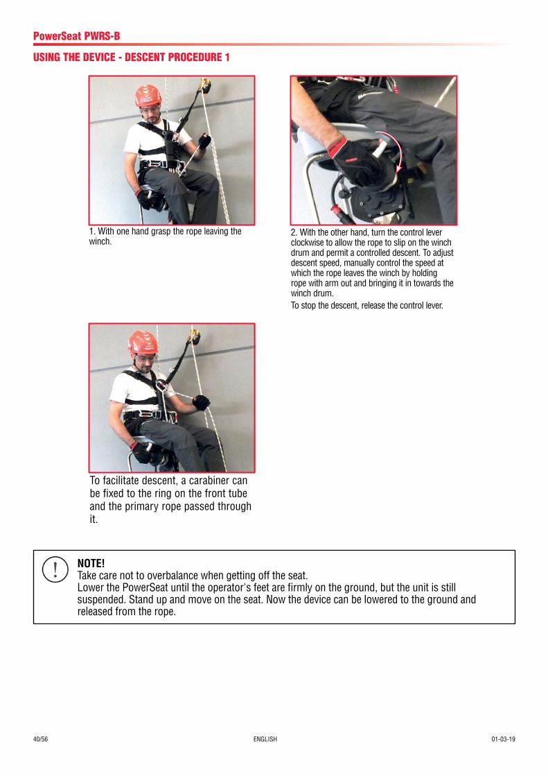
To facilitate descent, a carabiner can be fixed to the ring on the front tube and the primary rope passed through it.
1. With one hand grasp the rope leaving the winch.
2. With the other hand, turn the control lever clockwise to allow the rope to slip on the winch drum and permit a controlled descent. To adjust descent speed, manually control the speed at which the rope leaves the winch by holding rope with arm out and bringing it in towards the winch drum. To stop the descent, release the control lever.
NOTE!Take care not to overbalance when getting off the seat.Lower the PowerSeat until the operator's feet are firmly on the ground, but the unit is still suspended. Stand up and move on the seat. Now the device can be lowered to the ground and released from the rope.
01-03-19 ENGLISH 41/56
PowerSeat PWRS-B
USING THE DEVICE - TRANSPORT AND STORAGETransport the device using the box provvided at time of purchase. To transport the device disconnect the Power Supply system. When not in use the device must be stored in its box in order to protect it from knocks and shock. Protect the device from humidity and temperature range. The temperature required for storage must be in the range -25°C/+55°C, and for periods not exeeding 24 hours the maximum temperature can reach +70°C. The humidity is not expected to exeed 80%. Do not allow the device to come into contact with corrosive substances. Clean the device before storing.
USING THE DEVICE - FIXED ANCHORAGE DESCENT PROCEDURE1. With one hand grasp the rope leaving the winch.
2. With the other hand, turn the control lever clockwise to allow the rope to slip on the winch drum and permit a controlled descent. To adjust descent speed, manually control the speed at which the rope leaves the winch. To stop the descent, release the control lever.
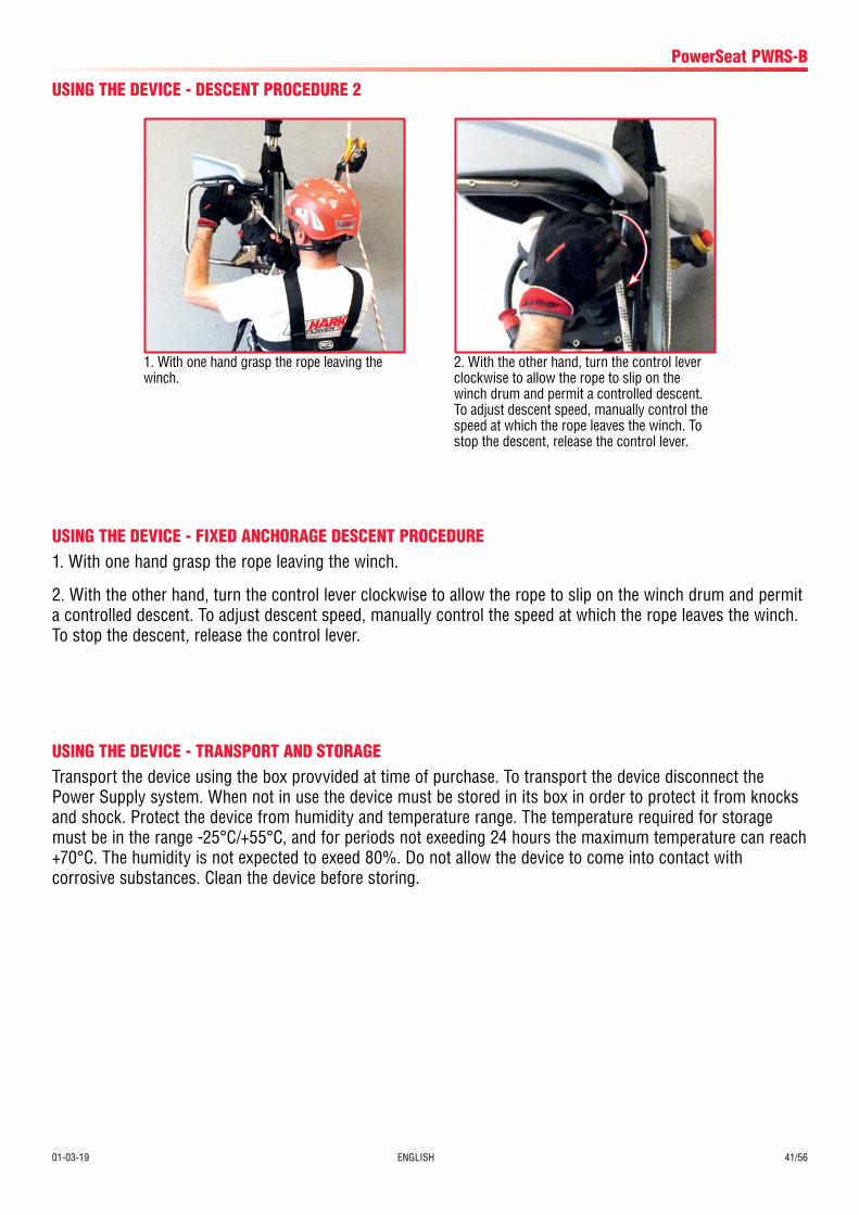
1. With one hand grasp the rope leaving the winch.
USING THE DEVICE - DESCENT PROCEDURE 2
2. With the other hand, turn the control lever clockwise to allow the rope to slip on the winch drum and permit a controlled descent. To adjust descent speed, manually control the speed at which the rope leaves the winch. To stop the descent, release the control lever.
42/56 ENGLISH 01-03-19
PowerSeat PWRS-B.Compact
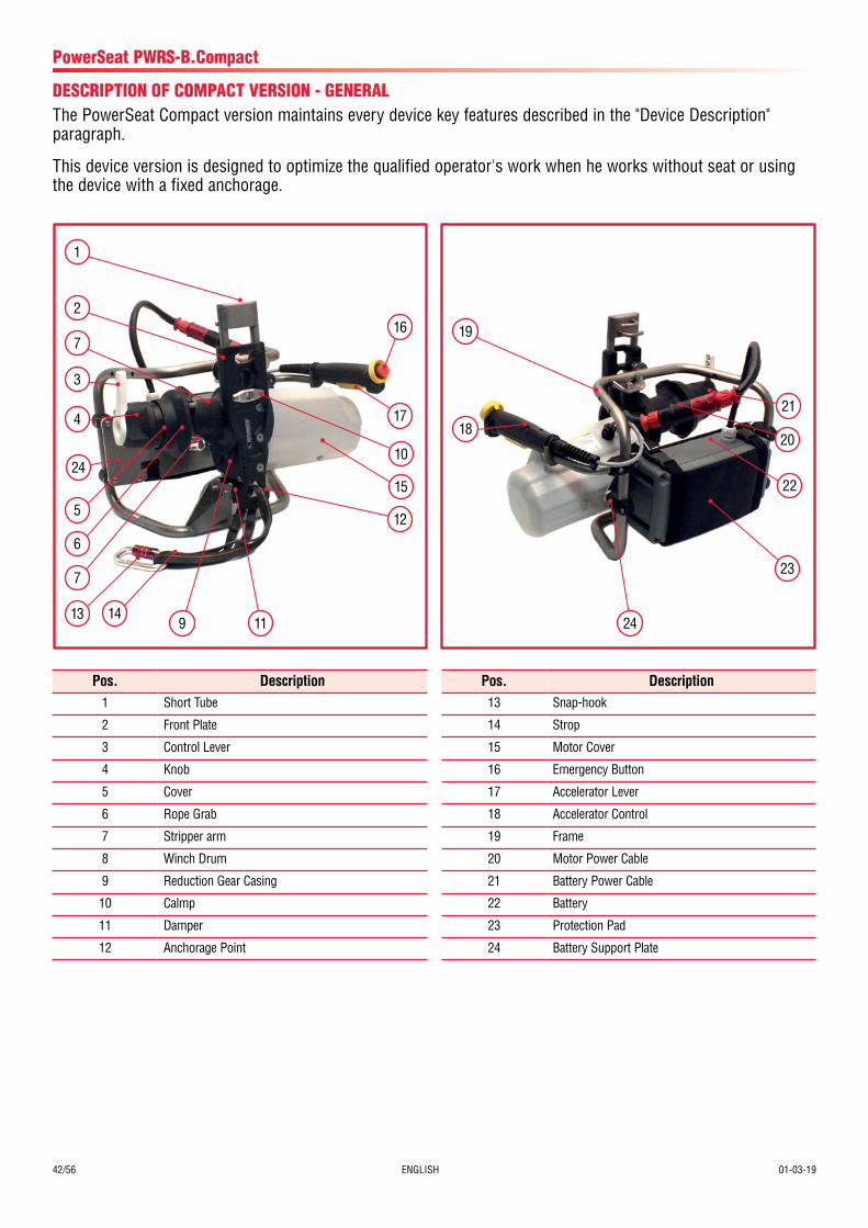
DESCRIPTION OF COMPACT VERSION - GENERALThe PowerSeat Compact version maintains every device key features described in the "Device Description" paragraph.
This device version is designed to optimize the qualified operator's work when he works without seat or using the device with a fixed anchorage.
Pos. Description1 Short Tube
2 Front Plate
3 Control Lever
4 Knob
5 Cover
6 Rope Grab
7 Stripper arm
8 Winch Drum
9 Reduction Gear Casing
10 Calmp
11 Damper
12 Anchorage Point
Pos. Description13 Snap-hook
14 Strop
15 Motor Cover
16 Emergency Button
17 Accelerator Lever
18 Accelerator Control
19 Frame
20 Motor Power Cable
21 Battery Power Cable
22 Battery
23 Protection Pad
24 Battery Support Plate
7
13 14
719
9 11 24
15 22
10
1721
20
16
12
23
1
2
4
24
18
3
5
6
01-03-19 ENGLISH 43/56
PowerSeat PWRS-B.Compact
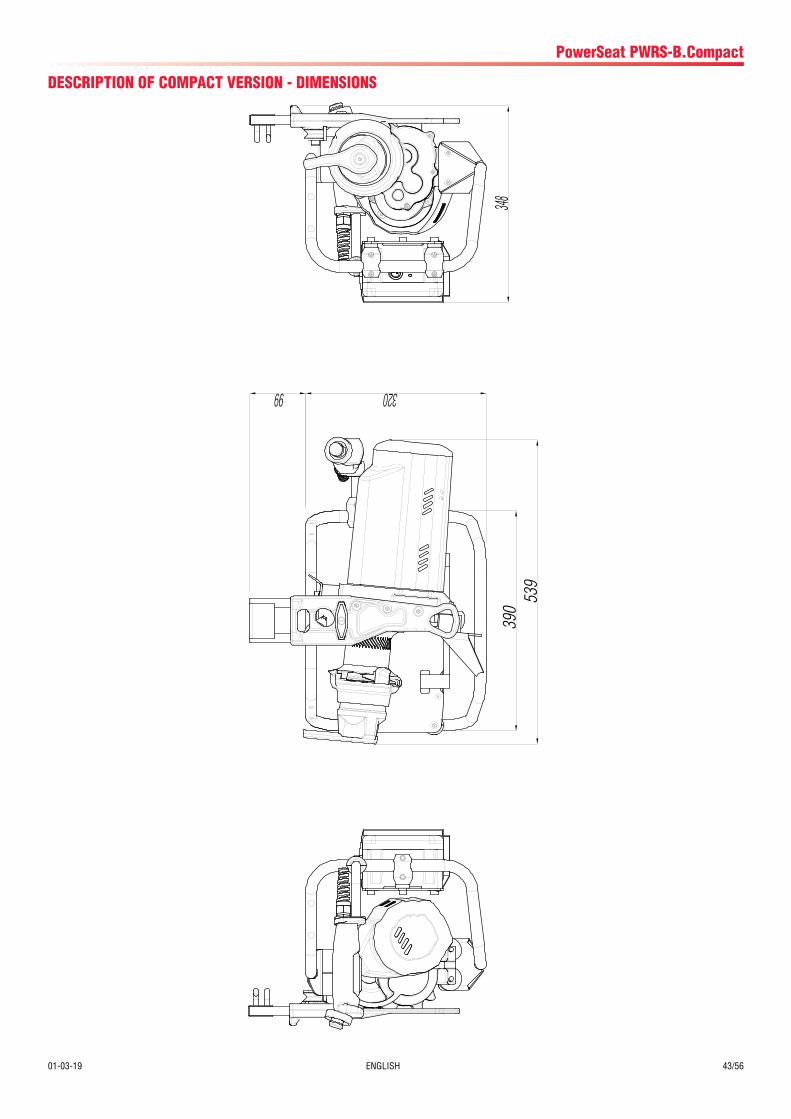
DESCRIPTION OF COMPACT VERSION - DIMENSIONS
390
348
99 320
539
44/56 ENGLISH 01-03-19
PowerSeat PWRS-B.Compact
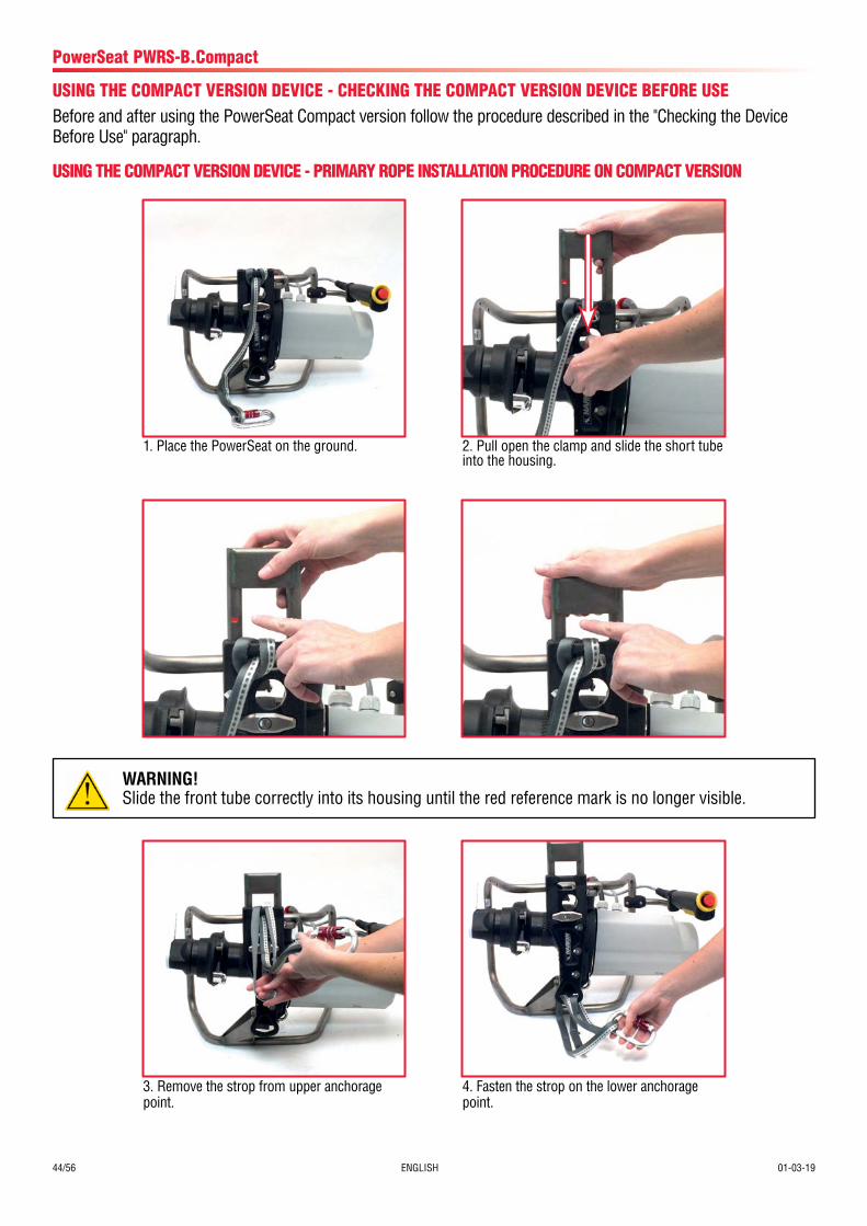
USING THE COMPACT VERSION DEVICE - CHECKING THE COMPACT VERSION DEVICE BEFORE USEBefore and after using the PowerSeat Compact version follow the procedure described in the "Checking the Device Before Use" paragraph.
1. Place the PowerSeat on the ground. 2. Pull open the clamp and slide the short tube into the housing.
3. Remove the strop from upper anchorage point.
4. Fasten the strop on the lower anchorage point.
USING THE COMPACT VERSION DEVICE - PRIMARY ROPE INSTALLATION PROCEDURE ON COMPACT VERSION
WARNING!Slide the front tube correctly into its housing until the red reference mark is no longer visible.
01-03-19 ENGLISH 45/56
PowerSeat PWRS-B.Compact
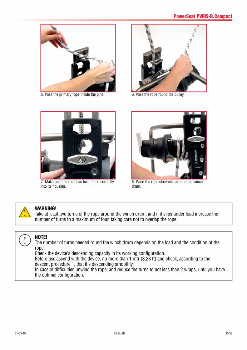
5. Pass the primary rope inside the pins.
7. Make sure the rope has been fitted correctly into its housing.
6. Pass the rope round the pulley.
8. Wind the rope clockwise around the winch drum.
WARNING!Take at least two turns of the rope around the winch drum, and if it slips under load increase the number of turns to a maximum of four, taking care not to overlap the rope.
NOTE!The number of turns needed round the winch drum depends on the load and the condition of the rope.Check the device's descending capacity in its working configuration.Before use ascend with the device, no more than 1 mtr (3,28 ft) and check, according to the descent procedure 1, that it's descending smoothly.In case of difficulties unwind the rope, and reduce the turns to not less than 2 wraps, until you have the optimal configuration.
46/56 ENGLISH 01-03-19
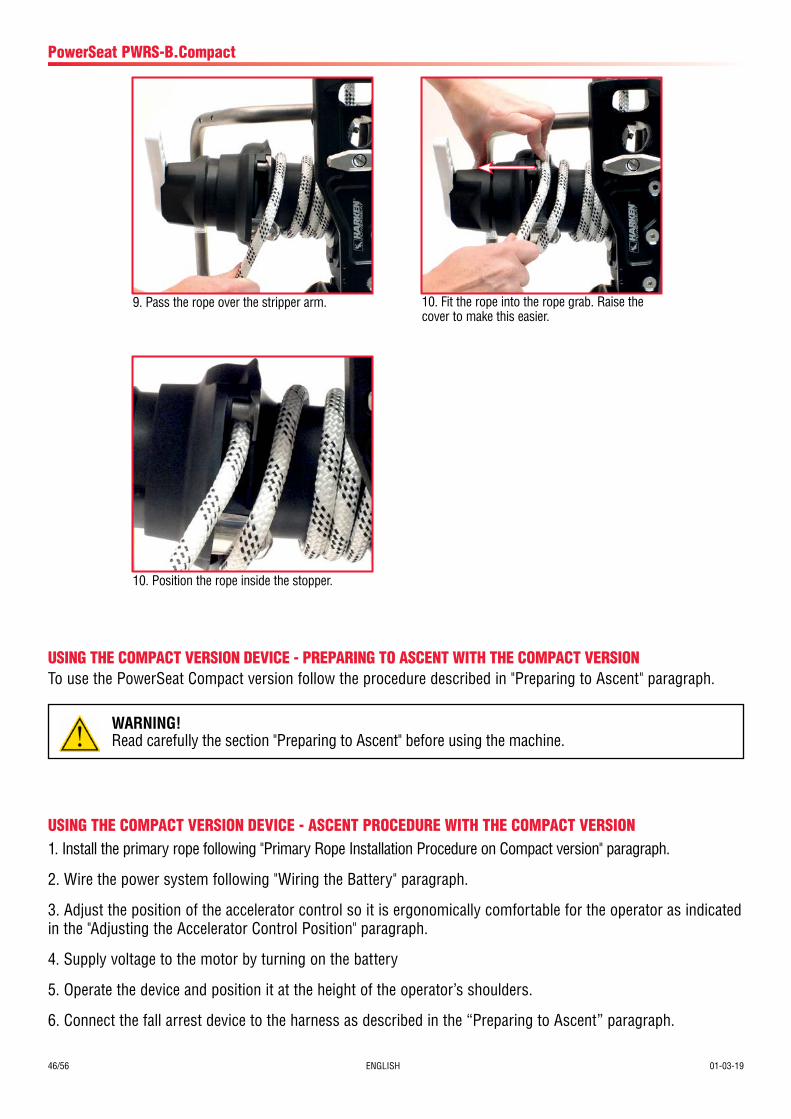
9. Pass the rope over the stripper arm. 10. Fit the rope into the rope grab. Raise the cover to make this easier.
10. Position the rope inside the stopper.
USING THE COMPACT VERSION DEVICE - ASCENT PROCEDURE WITH THE COMPACT VERSION1. Install the primary rope following "Primary Rope Installation Procedure on Compact version" paragraph.
2. Wire the power system following "Wiring the Battery" paragraph.
3. Adjust the position of the accelerator control so it is ergonomically comfortable for the operator as indicated in the "Adjusting the Accelerator Control Position" paragraph.
4. Supply voltage to the motor by turning on the battery
5. Operate the device and position it at the height of the operator’s shoulders.
6. Connect the fall arrest device to the harness as described in the “Preparing to Ascent” paragraph.
PowerSeat PWRS-B.Compact
USING THE COMPACT VERSION DEVICE - PREPARING TO ASCENT WITH THE COMPACT VERSIONTo use the PowerSeat Compact version follow the procedure described in "Preparing to Ascent" paragraph.
WARNING!Read carefully the section "Preparing to Ascent" before using the machine.
01-03-19 ENGLISH 47/56
USING THE COMPACT VERSION DEVICE - USING COMPACT VERSION POWERSEAT WITH A FIXED ANCHORAGE
1. Adjust the position of the accelerator control so it is ergonomically comfortable for the operator as indicated in the "Adjusting the Accelerator Control Position" paragraph.
2. Set the control lever position following the "Adjusting the Control Lever Position" paragraph.
3. Install the primary rope on the device as indicated in the “Primary rope installation procedure on Comapct version” paragraph. In this case the primary rope will be used to lift the second operator.
4. Wire the power supply system as described in the "Wiring the Battery" paragraph.
5. Connect the anchorage point on the front plate of the device with the fixed anchorage point on the ground.
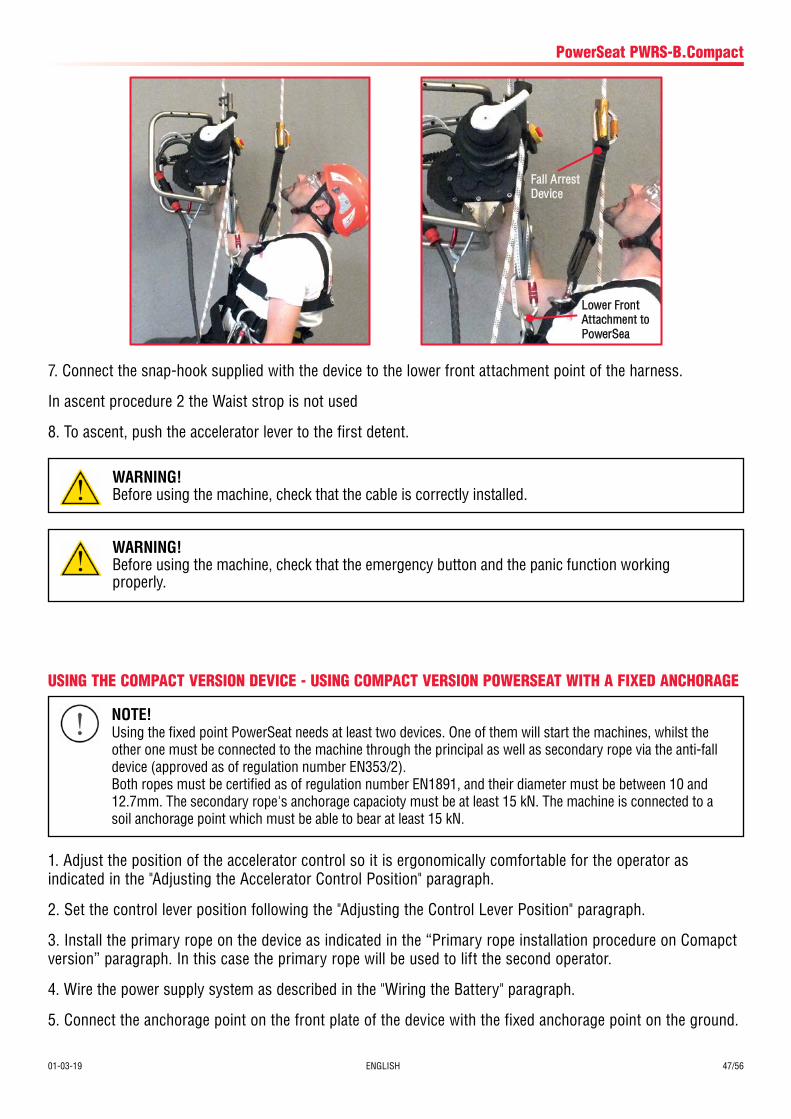
7. Connect the snap-hook supplied with the device to the lower front attachment point of the harness.
In ascent procedure 2 the Waist strop is not used
8. To ascent, push the accelerator lever to the first detent.
PowerSeat PWRS-B.Compact
WARNING!Before using the machine, check that the cable is correctly installed.
WARNING!Before using the machine, check that the emergency button and the panic function working properly.
NOTE!Using the fixed point PowerSeat needs at least two devices. One of them will start the machines, whilst the other one must be connected to the machine through the principal as well as secondary rope via the anti-fall device (approved as of regulation number EN353/2).Both ropes must be certified as of regulation number EN1891, and their diameter must be between 10 and 12.7mm. The secondary rope's anchorage capacioty must be at least 15 kN. The machine is connected to a soil anchorage point which must be able to bear at least 15 kN.
Lower Front Attachment to PowerSea
Fall Arrest Device
48/56 ENGLISH 01-03-19
PowerSeat PWRS-B.Compact
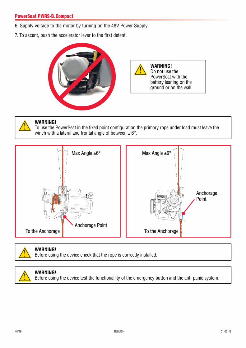
6. Supply voltage to the motor by turning on the 48V Power Supply.
7. To ascent, push the accelerator lever to the first detent.
WARNING!Before using the device check that the rope is correctly installed.
WARNING!Before using the device test the functionallity of the emergency button and the anti-panic system.
WARNING!To use the PowerSeat in the fixed point configuration the primary rope under load must leave the winch with a lateral and frontal angle of between ± 6°.
WARNING!Do not use the PowerSeat with the battery leaning on the ground or on the wall.
Max Angle ±6°
To the AnchorageAnchorage Point
Max Angle ±6°
To the Anchorage
Anchorage Point
01-03-19 ENGLISH 49/56
PowerSeat PWRS-B.Compact
USING THE COMPACT VERSION DEVICE - FIXED ANCHORAGE DESCENT PROCEDURE WITH THE COMPACT VERSION1. With one hand grasp the rope leaving the winch.
2. With the other hand, turn the control lever clockwise to allow the rope to slip on the winch drum and permit a controlled descent. To adjust descent speed, manually control the speed at which the rope leaves the winch. To stop the descent, release the control lever.
1. With one hand grasp the rope leaving the winch.
USING THE COMPACT VERSION DEVICE - DESCENT PROCEDURE WITH THE COMPACT VERSION
2. With the other hand, turn the control lever clockwise to allow the rope to slip on the winch drum and permit a controlled descent. To adjust descent speed, manually control the speed at which the rope leaves the winch. To stop the descent, release the control lever.
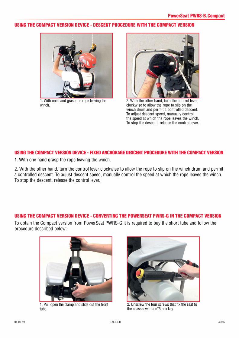
USING THE COMPACT VERSION DEVICE - CONVERTING THE POWERSEAT PWRS-G IN THE COMPACT VERSIONTo obtain the Compact version from PowerSeat PWRS-G it is required to buy the short tube and follow the procedure described below:
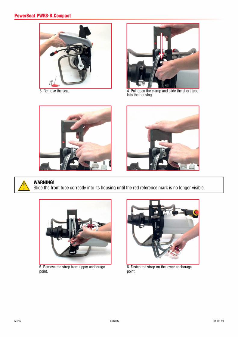
1. Pull open the clamp and slide out the front tube.
2. Unscrew the four screws that fix the seat to the chassis with a n°5 hex key.
50/56 ENGLISH 01-03-19
PowerSeat PWRS-B.Compact
3. Remove the seat. 4. Pull open the clamp and slide the short tube into the housing.
5. Remove the strop from upper anchorage point.
6. Fasten the strop on the lower anchorage point.
WARNING!Slide the front tube correctly into its housing until the red reference mark is no longer visible.
01-03-19 ENGLISH 51/56
CLEANINGRegularly clean and dry the device with a damp cloth to remove accumulated dirt. Do not use a direct jet of water or a high pressure water jet cleaner. Do not use degreasing products, solvents or abrasive pastes.
MAINTENANCEBefore and after every use visually inspect the PowerSeat for traces of wear, damage or breakage. Refer to the “Checking the device before use” paragraph for more detail on this inspection.
Every year, once a year send the device to the manufacturer or to an authorized Harken Service Center for a complete inspection. For a list of authorized service centers please visit the website www.power-seat.com.
The first year, the device must be sent to the manufacturer within 12 months from the date of purchase. The non-observance of such condition invalidates the warranty of the machine.
The maintenance must be recorded in the Maintenance Schedule.
Maintenance
Problem Possible Causes Possible SolutionsThe rope slips on the winch drum
- too few turns around the winch drum
- diameter of rope not in prescribed range
- take another turn of the rope round the winch drum
- replace the ropeThe engine does not start - incorrect engine starting procedure
- the ignition process is not correct and/or the bat-tery wiring
- engine fault
- it is activated the motor thermal protection
- refer to "Wiring the Power Supply System" para-graph in this User Manual- verify that the emergency button is disarmed- verify the integrity of the cable and its connectors- verify that the input voltage it is in the correct range
- refer to the "Diagnosis and Fault Finding" relative tothe battery
- contact Harken for more informations
- wait until the motor temperature is below the block temperature. This operation may take several tens of minutes.
Limited lifting capacity - engine malfunctioning
- overload condition
- contact Harken Tech Service for more informa-tions
- reduce the load
POWERSEAT AND ENGINE
Diagnosis and Fault Finding
When the device is dismantled, it is necessary to separate the parts in plastic, those in metal and electrical components, which must be sent to differentiated disposal centres in accordance with the regulations of the country where the device is dismantled.
Flat batteries must be sent to trash separation and collection points, respecting the current regulations of the country where the batteries will be disposed.
Dismalting and Disposal
52/56 ENGLISH 01-03-19
Diagnosis and Fault Finding
Difficult descent - too many wraps on winch drum
- rope grab system possible malfunctioning
- unwind the rope, reducing wraps. Leave at least 2 wraps on winch drum- contact Harken Tech Service for more informa-tions
Problem Possible Causes Possible SolutionsThe battery does not charge
- the battery charger is not connected (the light onthe battery charger is switched off)
- the battery is disconnected
- the battery is switched off
- battery temperature is outside the 0/+40 °C range
- the battery fuse is burned
- the battery charger fuse is burned
- the battery charger is damaged
- connect the battery charger
- verify the wiring
- verify that the power button has been pushed correctly
- wait for the temperature to come back to the 0/+40 range
- Unscrew the fuse holder and change the 5A 250V 5x20mm F fuse
- change the fuse (ATM - automotive mini - 7.5 A)
- change the battery chargerPWRS does not work - the battery is switched off
- the battery is disconnected
- the battery is in stand-by
- the battery is not charged (fixed red LED light)
- the temperature of the battery is outside the range -10/+50°C
- the battery is damaged
- the battery is in short circuit (all LEDs are swithced off)
- verify that the power button has been pushed correctly
- verify the wiring
- switch off and then switch on the battery
- verify that the battery is charged, and possibly charge it
- wait for the temperature to come back to the -10/+50 range
- the battery has to be sent to Harken in order to be repaired
- the battery has to be sent to Harken in order to be repaired
BATTERY
01-03-19 ENGLISH 53/56
Date of Service Description of Service Name and Signature of Maintanance Operator
Date of Next Intervention
Maintenance Schedule
Maintenance Schedule
Owner name
Product name and Model
Serial Number
Engine Serial Number
Year of manufacture
Date of purchase
Date of first use
Maintenance interval Annual

54/56 ENGLISH 01-03-19
Date of Service Description of Service Name and Signature of Maintanance Operator
Date of Next Intervention
Maintenance Schedule

Manufacturer/EU RepresentiveHarken Italy S.p.A.
Via Marco Biagi 14, 22070 Limido Comasco (CO), Italy Tel 031.3523511; Fax 031.3520031
Web: www.harken.it Email: [email protected]
Worldwide Limited Warranty
Refer to the Harken World Limited Warranty on the website at:
http://www.harkenindustrial.com/technical-information/warranty/
The product warranty is accepted only if it has been maintained as specified in this Manual by Harken authorized personnel and is accompanied by Maintenance Schedule properly compiled