Embed Size (px)
Citation preview
PowerSafe
Trusted Switchgear Technology
Commercial and Industrial Catalogue
SP&N Distribution BoardsTP&N Distribution BoardsMCCB PanelboardsSwitch Disconnector FuseModular Devices and Enclosures
Sw
itchg
ear

2 HAVELLS
At Havells, we aim to provide the very best customer
experience through our social media platforms. From the
latest industry news, to helpful installation videos, make sure
you check out Havells on YouTube and Twitter, and take
advantage of the tools and information available.
We’re Social
www.youtube.com/HavellsUK
www.twitter.com/HavellsUK
#HavellsSG

PowerSafe – Commercial & Industrial 3
TrustedSwitchgearTechnology
Havells is a global manufacturer of electrical and power distribution equipment. With state of the art factories, Havells have a capacity to produce more than 60 million poles of MCB/ RCD type products per year. The UK team lead customer innovation and design projects to ensure our customers benefit from UK market optimised solutions that meet local standards and regulatory requirements
Safety and ComplianceSafety and compliance is at the core of the Havells
philosophy, which is reflected in the 21 state of the art
manufacturing plants globally, producing acclaimed products
synonymous with excellence and safety. The MCB / RCCB
/ RCBO plant in Baddi, India, is now the sixth largest MCB
plant in the world. Many of the products from this plant carry
the KEMA –KEUR quality mark. The mark is only achieved
through continuous independent testing of products and
processes, based on strict international standards.
A shared input to innovation and excellenceCustomer input creates opportunities for innovation,
which is reflected in Havells product solutions. Our core
competence is circuit protection and control through circuit
breaker and RCD technologies. However, there are other
important technologies which directly impact electrical
distribution in modern commercial buildings. In the UK,
these technologies are applied to electrical distribution
in specific ways, to address local norms and regulatory
requirements. By partnering with ‘best in Class’ technology
partners, Havells offer some uniquely innovative solutions in
these areas. Metering and Voltage surge protection solutions
are examples of UK specific requirements, where Havells
have created practical and understandable solutions to
the requirements of modern commercial buildings. A guide
to surge protection and metering as applied in the UK are
provided in this literature.
4 HAVELLS
Type A SPN Distribution Board
Type B 125A TPN Distribution Board
Type B 250A TPN Distribution Board
Tri-Load TPN Distribution Board
Modular Devices and Enclosures
MCCB Panelboards
LoadSafe Enclosed Switch Disconnector Fuse
Guide to Metering Solutions
Guide to Surge Protection
Technical Data
Page 8
Page 12
Page 19
Page 24
Page 30
Page 34
Page 46
Page 50
Page 52
Page 58
Contents

PowerSafe – Commercial & Industrial 5
Practical solutions for tomorrow’s buildingsOur UK team works with over 200 engineers at Havells QRG
Centre for research and Innovation, developing new switchgear
products which compliment the evolving regulations and
standards in the UK, providing compliant solutions with a
hassle free approach for the installer. We are committed to
understanding the needs of our customers and continue to
bring new ideas and solutions for electrical distribution. Product
innovation is at the heart of Havells Switchgear and getting close
to the issues facing the installer today, enables our team to find
solutions for tomorrow.
Custom EngineeringWith many years of manufacturing and engineering
experience in the Electrical Industry, the Newhaven plant
based in East Sussex provides local solutions tailored to
meet a range of project requirements.
Key facilities include a fully automated paint plant, steel and
copper fabrication and dedicated switchgear assembly lines
offering customised solutions from pre-population of final
circuit protection devices to sub distribution boards with
integral metering and voltage surge protection.
Dedicated Switchgear Sales TeamOur Switchgear sales team know switchgear and have
electrically qualified team members providing high quality
local support to customers. With much of the product design
led from the UK, the sales team and customers benefit from
a wider support network within the Havells UK organisation.
We value customer input and strive to be your trusted choice
for Switchgear solutions.
A continualstrive for excellence

6 HAVELLS
The existing enclosed switch disconnector fuse
portfolio has been further extended up to 400A. With
two new frame sizes covering ratings from 160A to
400A in TPN and TPsN Pole configurations the range
is ideal for industrial applications requiring AC23A
utilisation category. Other additions include separate
fuse and isolator versions which can now be ordered
specifically to suit requirements as necessary.
Enclosed Earth Leakage Monitoring Solutions
To meet the demanding requirements of modern buildings the PowerSafe portfolio
now includes a range of earth leakage monitoring relays and core balance current
transformers.
Designed for applications where there is a TT earthing system or a high earth loop
impedance on the main electrical supply the new earth leakage monitoring offers
excellent protection against residual currents and earth faults.
Supplied as complete kits for use with MCB and MCCB distribution boards the
range provides user selectable parameters of sensitivity (A) and time delay (sec) to
specifically meet project requirements. The earth leakage monitoring devices also
feature a digital display which provides real time instantaneous “leakage” values
and has an auxiliary contact to connect to a BMS system for remote monitoring.
LoadSafe - Enclosed Switch Disconnector Fuse 160A - 400A SDF Range
• Conforms to BS EN 60947-3
• 80kA Withstand Rating
• Front Operated Door Interlocked with defeat mechanism
• Handle can be padlocked in ON and OFF position
• AC23A Utilisation Category
• Full range of matching cable spreader boxes
New for 2016
PowerSafe – Commercial & Industrial 7
New for 2016
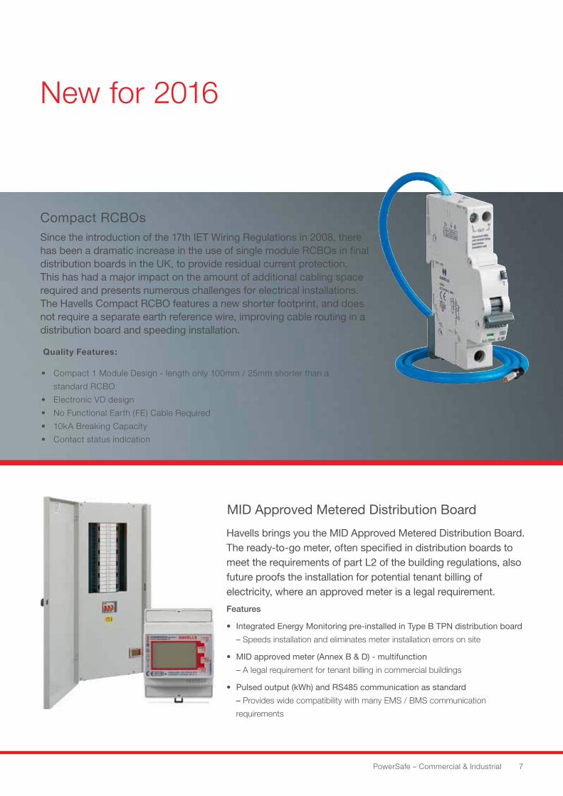
Compact RCBOsSince the introduction of the 17th IET Wiring Regulations in 2008, there has been a dramatic increase in the use of single module RCBOs in final distribution boards in the UK, to provide residual current protection. This has had a major impact on the amount of additional cabling space required and presents numerous challenges for electrical installations. The Havells Compact RCBO features a new shorter footprint, and does not require a separate earth reference wire, improving cable routing in a distribution board and speeding installation.
Quality Features:
• Compact 1 Module Design - length only 100mm / 25mm shorter than a
standard RCBO
• Electronic VD design
• No Functional Earth (FE) Cable Required
• 10kA Breaking Capacity
• Contact status indication
Havells brings you the MID Approved Metered Distribution Board.The ready-to-go meter, often specified in distribution boards tomeet the requirements of part L2 of the building regulations, alsofuture proofs the installation for potential tenant billing of electricity, where an approved meter is a legal requirement.
Features
• Integrated Energy Monitoring pre-installed in Type B TPN distribution board
– Speeds installation and eliminates meter installation errors on site
• MID approved meter (Annex B & D) - multifunction
– A legal requirement for tenant billing in commercial buildings
• Pulsed output (kWh) and RS485 communication as standard
– Provides wide compatibility with many EMS / BMS communication
requirements
MID Approved Metered Distribution Board
8 HAVELLS
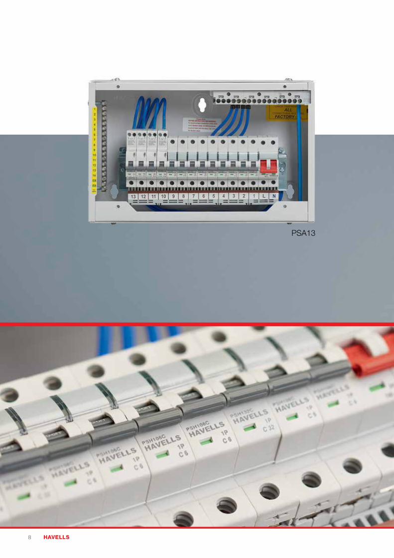
PSA13
PowerSafe – Commercial & Industrial 9
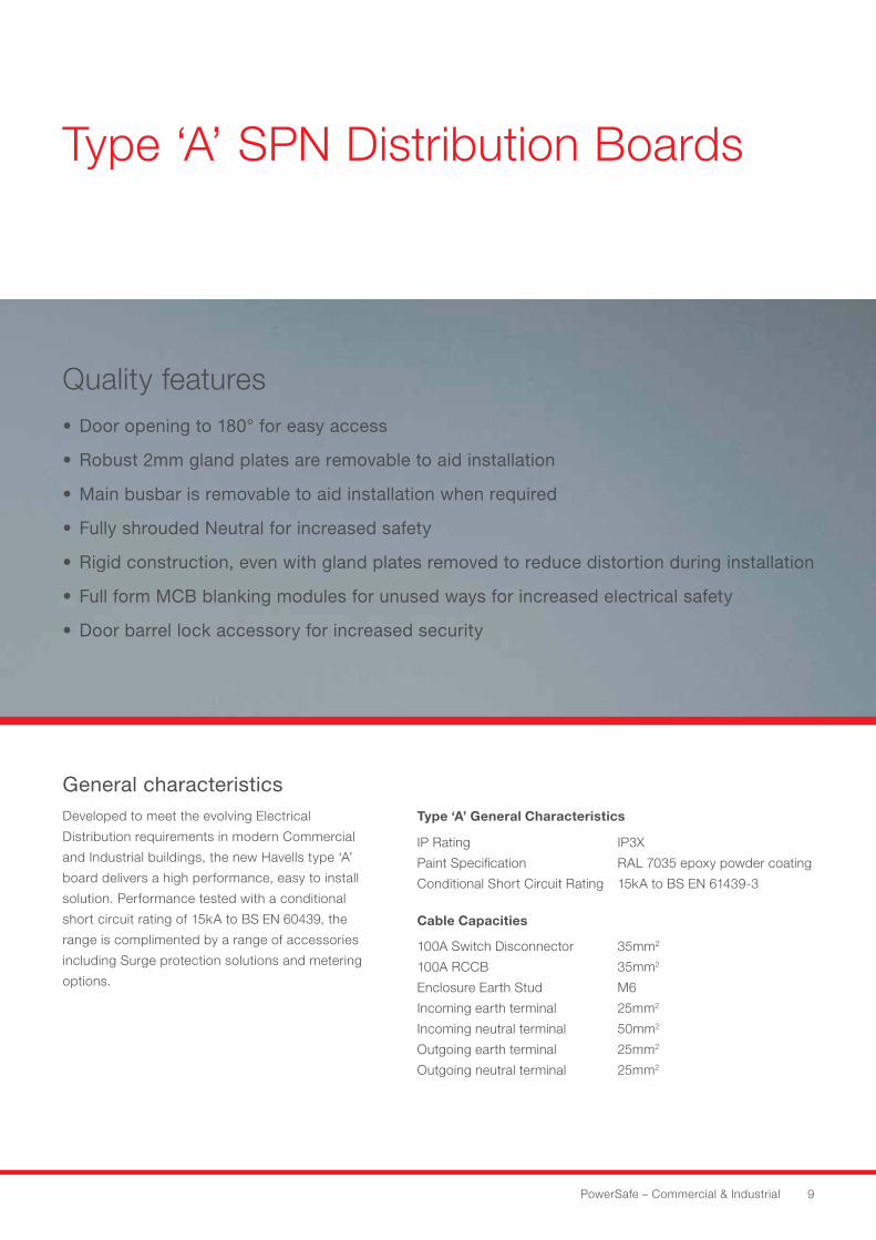
Type ‘A’ SPN Distribution Boards
Quality features• Door opening to 180° for easy access
• Robust 2mm gland plates are removable to aid installation
• Main busbar is removable to aid installation when required
• Fully shrouded Neutral for increased safety
• Rigid construction, even with gland plates removed to reduce distortion during installation
• Full form MCB blanking modules for unused ways for increased electrical safety
• Door barrel lock accessory for increased security
General characteristicsDeveloped to meet the evolving Electrical
Distribution requirements in modern Commercial
and Industrial buildings, the new Havells type ‘A’
board delivers a high performance, easy to install
solution. Performance tested with a conditional
short circuit rating of 15kA to BS EN 60439, the
range is complimented by a range of accessories
including Surge protection solutions and metering
options.
Type ‘A’ General Characteristics
IP Rating
Paint Specification
Conditional Short Circuit Rating
IP3X
RAL 7035 epoxy powder coating
15kA to BS EN 61439-3
Cable Capacities
100A Switch Disconnector
100A RCCB
Enclosure Earth Stud
Incoming earth terminal
Incoming neutral terminal
Outgoing earth terminal
Outgoing neutral terminal
35mm2
35mm2
M6
25mm2
50mm2
25mm2
25mm2
10 HAVELLS
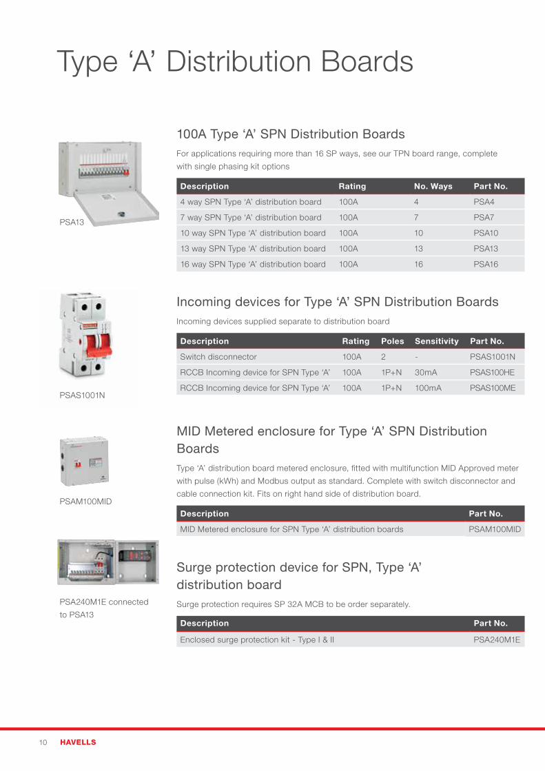
Type ‘A’ Distribution Boards
100A Type ‘A’ SPN Distribution BoardsFor applications requiring more than 16 SP ways, see our TPN board range, complete
with single phasing kit options
Description Rating No. Ways Part No.
4 way SPN Type ‘A’ distribution board 100A 4 PSA4
7 way SPN Type ‘A’ distribution board 100A 7 PSA7
10 way SPN Type ‘A’ distribution board 100A 10 PSA10
13 way SPN Type ‘A’ distribution board 100A 13 PSA13
16 way SPN Type ‘A’ distribution board 100A 16 PSA16
Incoming devices for Type ‘A’ SPN Distribution BoardsIncoming devices supplied separate to distribution board
Description Rating Poles Sensitivity Part No.
Switch disconnector 100A 2 - PSAS1001N
RCCB Incoming device for SPN Type ‘A’ 100A 1P+N 30mA PSAS100HE
RCCB Incoming device for SPN Type ‘A’ 100A 1P+N 100mA PSAS100ME
MID Metered enclosure for Type ‘A’ SPN Distribution Boards Type ‘A’ distribution board metered enclosure, fitted with multifunction MID Approved meter
with pulse (kWh) and Modbus output as standard. Complete with switch disconnector and
cable connection kit. Fits on right hand side of distribution board.
Description Part No.
MID Metered enclosure for SPN Type ‘A’ distribution boards PSAM100MID
Surge protection device for SPN, Type ‘A’ distribution board Surge protection requires SP 32A MCB to be order separately.
Description Part No.
Enclosed surge protection kit - Type I & II PSA240M1E
PSA13
PSAS1001N
PSA240M1E connected
to PSA13
PSAM100MID
PowerSafe – Commercial & Industrial 11
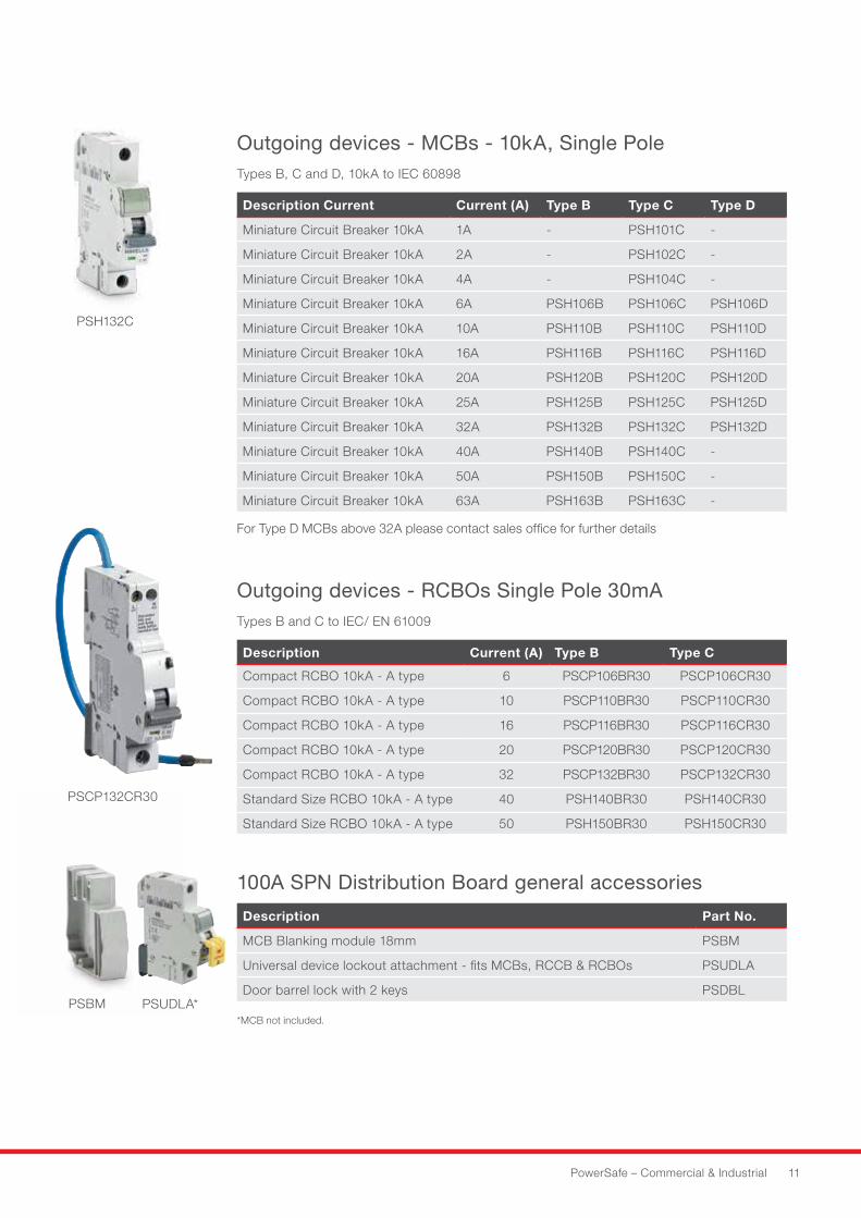
Outgoing devices - MCBs - 10kA, Single Pole Types B, C and D, 10kA to IEC 60898
Description Current Current (A) Type B Type C Type D
Miniature Circuit Breaker 10kA 1A - PSH101C -
Miniature Circuit Breaker 10kA 2A - PSH102C -
Miniature Circuit Breaker 10kA 4A - PSH104C -
Miniature Circuit Breaker 10kA 6A PSH106B PSH106C PSH106D
Miniature Circuit Breaker 10kA 10A PSH110B PSH110C PSH110D
Miniature Circuit Breaker 10kA 16A PSH116B PSH116C PSH116D
Miniature Circuit Breaker 10kA 20A PSH120B PSH120C PSH120D
Miniature Circuit Breaker 10kA 25A PSH125B PSH125C PSH125D
Miniature Circuit Breaker 10kA 32A PSH132B PSH132C PSH132D
Miniature Circuit Breaker 10kA 40A PSH140B PSH140C -
Miniature Circuit Breaker 10kA 50A PSH150B PSH150C -
Miniature Circuit Breaker 10kA 63A PSH163B PSH163C -
For Type D MCBs above 32A please contact sales office for further details
Outgoing devices - RCBOs Single Pole 30mA Types B and C to IEC/ EN 61009
Description Current (A) Type B Type C
Compact RCBO 10kA - A type 6 PSCP106BR30 PSCP106CR30
Compact RCBO 10kA - A type 10 PSCP110BR30 PSCP110CR30
Compact RCBO 10kA - A type 16 PSCP116BR30 PSCP116CR30
Compact RCBO 10kA - A type 20 PSCP120BR30 PSCP120CR30
Compact RCBO 10kA - A type 32 PSCP132BR30 PSCP132CR30
Standard Size RCBO 10kA - A type 40 PSH140BR30 PSH140CR30
Standard Size RCBO 10kA - A type 50 PSH150BR30 PSH150CR30
100A SPN Distribution Board general accessories
Description Part No.
MCB Blanking module 18mm PSBM
Universal device lockout attachment - fits MCBs, RCCB & RCBOs PSUDLA
Door barrel lock with 2 keys PSDBL PSBM
PSH132C
PSCP132CR30
PSUDLA**MCB not included.
12 HAVELLS
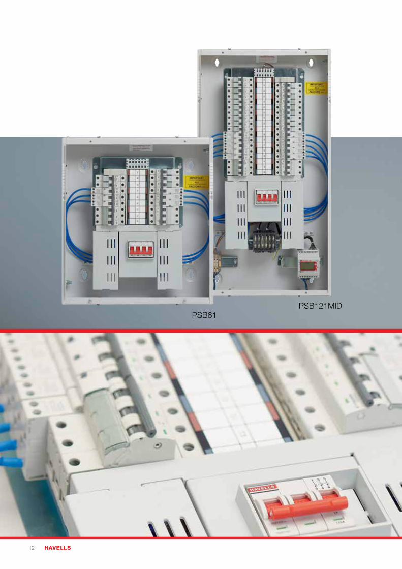
PSB61PSB121MID
PowerSafe – Commercial & Industrial 13
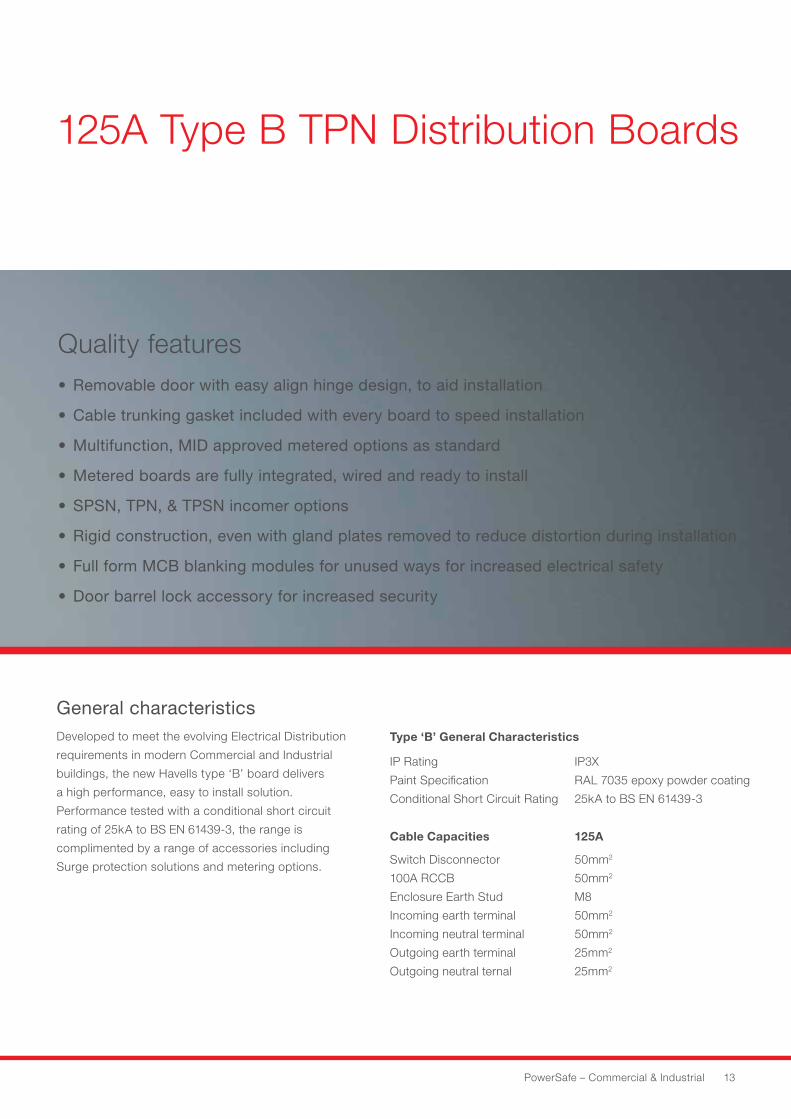
Type ‘B’ General Characteristics
IP Rating
Paint Specification
Conditional Short Circuit Rating
IP3X
RAL 7035 epoxy powder coating
25kA to BS EN 61439-3
Cable Capacities 125A
Switch Disconnector
100A RCCB
Enclosure Earth Stud
Incoming earth terminal
Incoming neutral terminal
Outgoing earth terminal
Outgoing neutral ternal
50mm2
50mm2
M8
50mm2
50mm2
25mm2
25mm2
125A Type B TPN Distribution Boards
Quality features• Removable door with easy align hinge design, to aid installation
• Cable trunking gasket included with every board to speed installation
• Multifunction, MID approved metered options as standard
• Metered boards are fully integrated, wired and ready to install
• SPSN, TPN, & TPSN incomer options
• Rigid construction, even with gland plates removed to reduce distortion during installation
• Full form MCB blanking modules for unused ways for increased electrical safety
• Door barrel lock accessory for increased security
General characteristicsDeveloped to meet the evolving Electrical Distribution
requirements in modern Commercial and Industrial
buildings, the new Havells type ‘B’ board delivers
a high performance, easy to install solution.
Performance tested with a conditional short circuit
rating of 25kA to BS EN 61439-3, the range is
complimented by a range of accessories including
Surge protection solutions and metering options.
14 HAVELLS
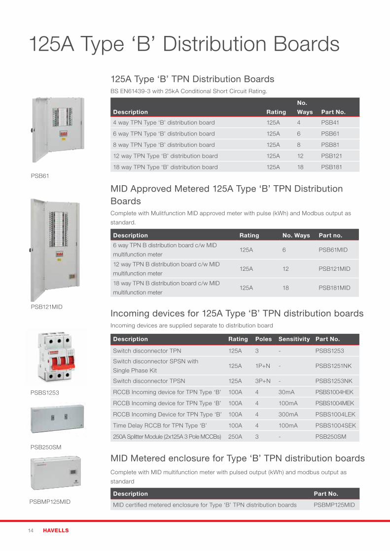
125A Type ‘B’ Distribution Boards
125A Type ‘B’ TPN Distribution Boards BS EN61439-3 with 25kA Conditional Short Circuit Rating.
Description Rating
No.
Ways Part No.
4 way TPN Type ‘B’ distribution board 125A 4 PSB41
6 way TPN Type ‘B’ distribution board 125A 6 PSB61
8 way TPN Type ‘B’ distribution board 125A 8 PSB81
12 way TPN Type ‘B’ distribution board 125A 12 PSB121
18 way TPN Type ‘B’ distribution board 125A 18 PSB181
MID Approved Metered 125A Type ‘B’ TPN Distribution BoardsComplete with Mulitfunction MID approved meter with pulse (kWh) and Modbus output as
standard.
Description Rating No. Ways Part no.
6 way TPN B distribution board c/w MID
multifunction meter125A 6 PSB61MID
12 way TPN B distribution board c/w MID
multifunction meter 125A 12 PSB121MID
18 way TPN B distribution board c/w MID
multifunction meter125A 18 PSB181MID
Incoming devices for 125A Type ‘B’ TPN distribution boards Incoming devices are supplied separate to distribution board
Description Rating Poles Sensitivity Part No.
Switch disconnector TPN 125A 3 - PSBS1253
Switch disconnector SPSN with
Single Phase Kit 125A 1P+N - PSBS1251NK
Switch disconnector TPSN 125A 3P+N - PSBS1253NK
RCCB Incoming device for TPN Type ‘B’ 100A 4 30mA PSBS1004HEK
RCCB Incoming device for TPN Type ‘B’ 100A 4 100mA PSBS1004MEK
RCCB Incoming Device for TPN Type ‘B’ 100A 4 300mA PSBS1004LEK
Time Delay RCCB for TPN Type ‘B’ 100A 4 100mA PSBS1004SEK
250A Splitter Module (2x125A 3 Pole MCCBs) 250A 3 - PSB250SM
MID Metered enclosure for Type ‘B’ TPN distribution boardsComplete with MID multifunction meter with pulsed output (kWh) and modbus output as
standard
Description Part No.
MID certified metered enclosure for Type ‘B’ TPN distribution boards PSBMP125MID
PSB61
PSB121MID
PSBS1253
PSB250SM
PSBMP125MID
PowerSafe – Commercial & Industrial 15
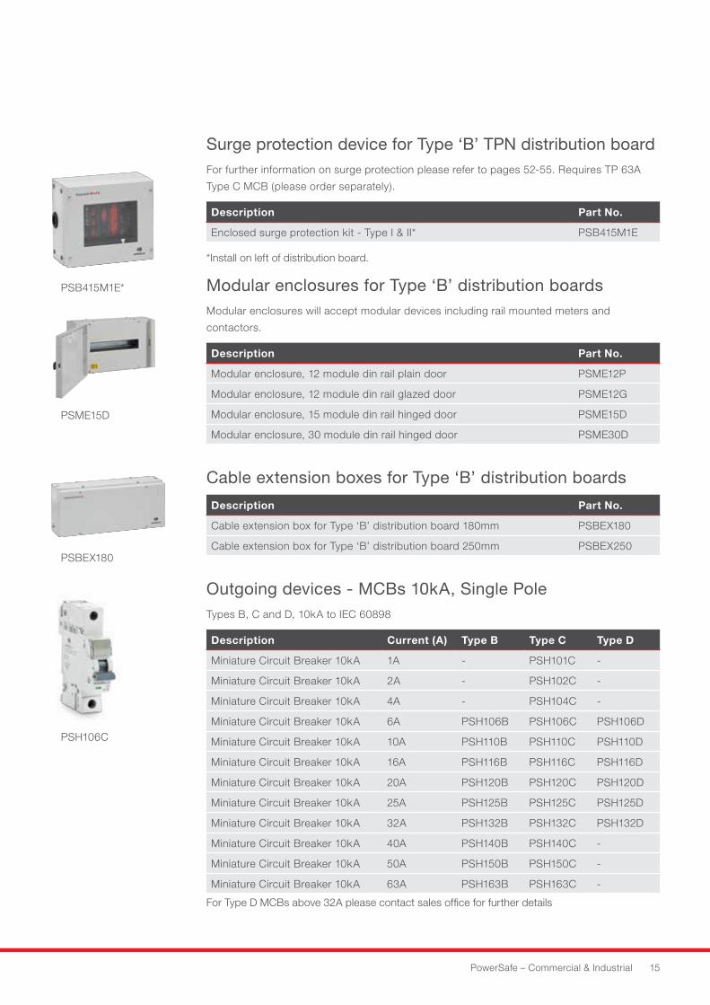
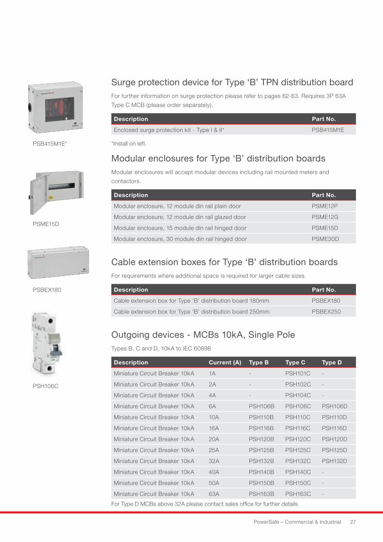
Surge protection device for Type ‘B’ TPN distribution board For further information on surge protection please refer to pages 52-55. Requires TP 63A
Type C MCB (please order separately).
Description Part No.
Enclosed surge protection kit - Type I & II* PSB415M1E
*Install on left of distribution board.
Modular enclosures for Type ‘B’ distribution boards Modular enclosures will accept modular devices including rail mounted meters and
contactors.
Description Part No.
Modular enclosure, 12 module din rail plain door PSME12P
Modular enclosure, 12 module din rail glazed door PSME12G
Modular enclosure, 15 module din rail hinged door PSME15D
Modular enclosure, 30 module din rail hinged door PSME30D
Cable extension boxes for Type ‘B’ distribution boards
Description Part No.
Cable extension box for Type ‘B’ distribution board 180mm PSBEX180
Cable extension box for Type ‘B’ distribution board 250mm PSBEX250
Outgoing devices - MCBs 10kA, Single Pole Types B, C and D, 10kA to IEC 60898
Description Current (A) Type B Type C Type D
Miniature Circuit Breaker 10kA 1A - PSH101C -
Miniature Circuit Breaker 10kA 2A - PSH102C -
Miniature Circuit Breaker 10kA 4A - PSH104C -
Miniature Circuit Breaker 10kA 6A PSH106B PSH106C PSH106D
Miniature Circuit Breaker 10kA 10A PSH110B PSH110C PSH110D
Miniature Circuit Breaker 10kA 16A PSH116B PSH116C PSH116D
Miniature Circuit Breaker 10kA 20A PSH120B PSH120C PSH120D
Miniature Circuit Breaker 10kA 25A PSH125B PSH125C PSH125D
Miniature Circuit Breaker 10kA 32A PSH132B PSH132C PSH132D
Miniature Circuit Breaker 10kA 40A PSH140B PSH140C -
Miniature Circuit Breaker 10kA 50A PSH150B PSH150C -
Miniature Circuit Breaker 10kA 63A PSH163B PSH163C -
For Type D MCBs above 32A please contact sales office for further details
PSH106C
PSB415M1E*
PSBEX180
PSME15D
16 HAVELLS
PSBIFK
PSBM
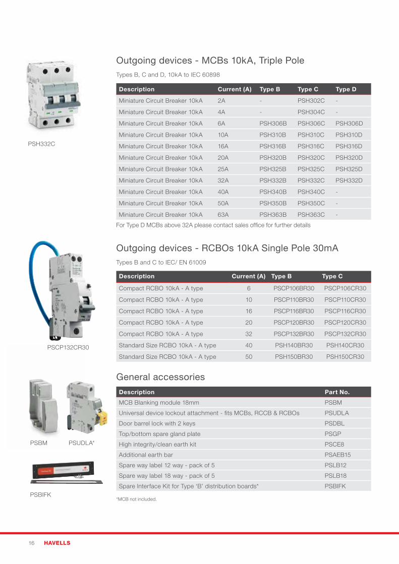
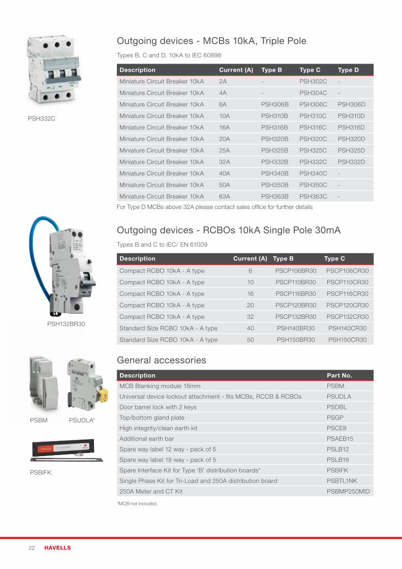
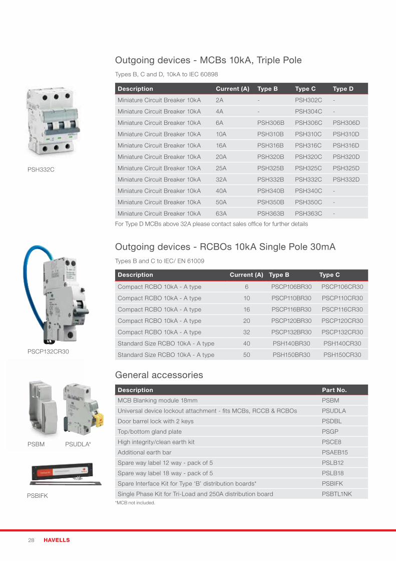
Outgoing devices - MCBs 10kA, Triple Pole Types B, C and D, 10kA to IEC 60898
Description Current (A) Type B Type C Type D
Miniature Circuit Breaker 10kA 2A - PSH302C -
Miniature Circuit Breaker 10kA 4A - PSH304C -
Miniature Circuit Breaker 10kA 6A PSH306B PSH306C PSH306D
Miniature Circuit Breaker 10kA 10A PSH310B PSH310C PSH310D
Miniature Circuit Breaker 10kA 16A PSH316B PSH316C PSH316D
Miniature Circuit Breaker 10kA 20A PSH320B PSH320C PSH320D
Miniature Circuit Breaker 10kA 25A PSH325B PSH325C PSH325D
Miniature Circuit Breaker 10kA 32A PSH332B PSH332C PSH332D
Miniature Circuit Breaker 10kA 40A PSH340B PSH340C -
Miniature Circuit Breaker 10kA 50A PSH350B PSH350C -
Miniature Circuit Breaker 10kA 63A PSH363B PSH363C -
For Type D MCBs above 32A please contact sales office for further details
Outgoing devices - RCBOs 10kA Single Pole 30mA Types B and C to IEC/ EN 61009
Description Current (A) Type B Type C
Compact RCBO 10kA - A type 6 PSCP106BR30 PSCP106CR30
Compact RCBO 10kA - A type 10 PSCP110BR30 PSCP110CR30
Compact RCBO 10kA - A type 16 PSCP116BR30 PSCP116CR30
Compact RCBO 10kA - A type 20 PSCP120BR30 PSCP120CR30
Compact RCBO 10kA - A type 32 PSCP132BR30 PSCP132CR30
Standard Size RCBO 10kA - A type 40 PSH140BR30 PSH140CR30
Standard Size RCBO 10kA - A type 50 PSH150BR30 PSH150CR30
General accessories
Description Part No.
MCB Blanking module 18mm PSBM
Universal device lockout attachment - fits MCBs, RCCB & RCBOs PSUDLA
Door barrel lock with 2 keys PSDBL
Top/bottom spare gland plate PSGP
High integrity/clean earth kit PSCE8
Additional earth bar PSAEB15
Spare way label 12 way - pack of 5 PSLB12
Spare way label 18 way - pack of 5 PSLB18
Spare Interface Kit for Type ‘B’ distribution boards* PSBIFK
PSH332C
PSCP132CR30
PSUDLA*
*MCB not included.
PowerSafe – Commercial & Industrial 17
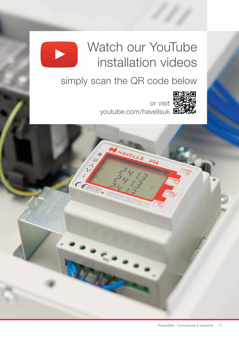
Watch our YouTube installation videos
simply scan the QR code below
or visit youtube.com/havellsuk
18 HAVELLS
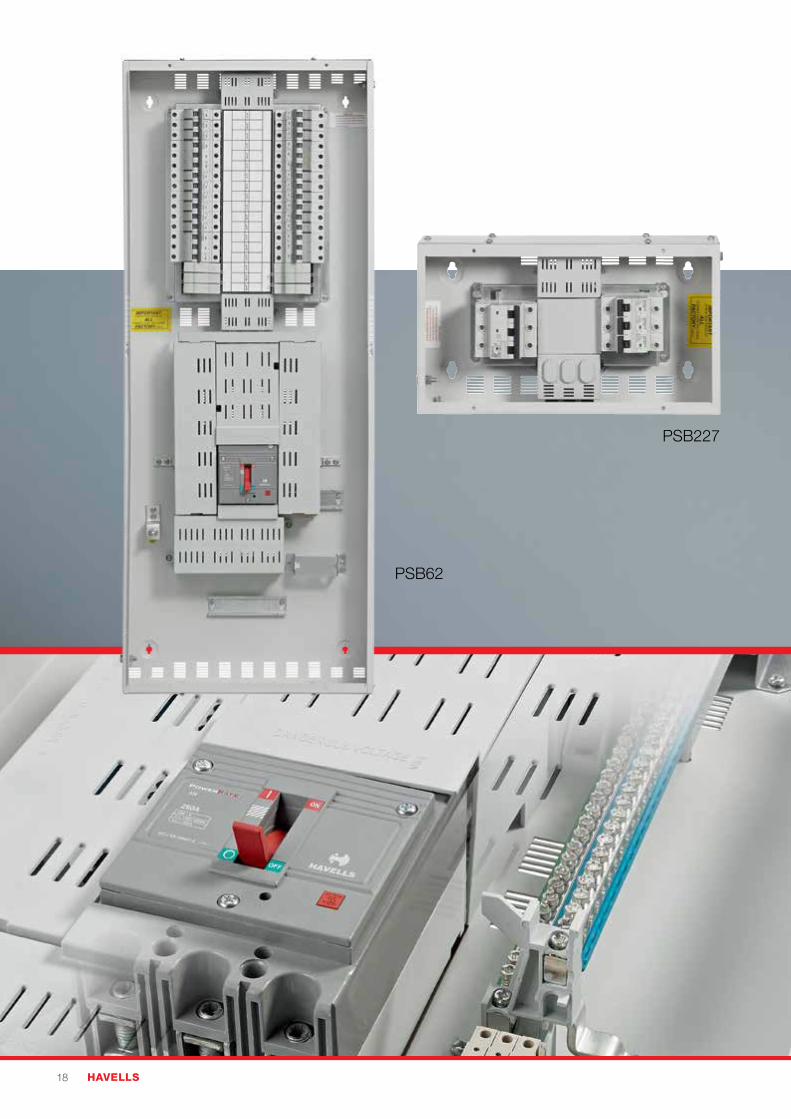
PSB62
PSB227
PowerSafe – Commercial & Industrial 19
250A Type B TPN Distribution boards
Quality features• Bolted earth, neutral and phase connections suitable for larger cables
• Removable door with easy align hinge design, to aid installation
• Cable trunking gasket included with every board to speed installation
• Integral metering options available
• TPN, & TPSN incomer options
• Rigid construction, even with gland plates removed to reduce distortion during installation
• Full form MCB blanking modules for unused ways for increased electrical safety
• Door barrel lock accessory for increased security
B Type General Characteristics
IP Rating
Paint Specification
Conditional Short Circuit Rating
IP3X
RAL 7035 epoxy powder coating
25kA to BS EN 61439-3
Cable Capacities 250A
Switch Disconnector
Enclosure Earth Stud
Incoming earth terminal
Incoming neutral terminal
Outgoing earth terminal
Outgoing neutral terminal
High current MCB’s
120mm2 (M8)
M8
50mm2
50mm2
25mm2
25mm2
50mm2
General characteristicsSpecifically designed to address applications
requiring electrical supplies larger than 125A the
250A Type B distribution board range also features
an optional add-on high current MCB extension
box designed for outgoing circuits above 63A. This
unique combined solution offers a cost effective
alternative to an MCCB panelboard where only one
or two outgoing circuits are required. The range is
complimented by a range of accessories including
Surge protection, MID metering and NEW earth
leakage monitoring solutions for compliance with
local UK regulations.
PSB227
20 HAVELLS
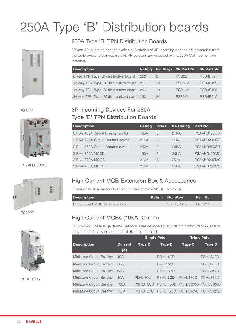
250A Type ‘B’ TPN Distribution Boards 3P and 4P incoming options available. A choice of 3P Incoming options are selectable from
the table below (order separately). 4P versions are supplied with a 250A Cbi incomer, pre-
installed.
Description Rating No. Ways 3P Part No. 4P Part No.
6 way TPN Type ‘B’ distribution board 250 6 PSB62 PSB4P62
12 way TPN Type ‘B’ distribution board 250 12 PSB122 PSB4P122
18 way TPN Type ‘B’ distribution board 250 18 PSB182 PSB4P182
24 way TPN Type ‘B’ distribution board 250 24 PSB242 PSB4P242
3P Incoming Devices For 250A Type ‘B’ TPN Distribution Boards
Description Rating Poles kA Rating Part No.
3 Pole 125A Circuit Breaker switch 125A 3 25kA PSAAN3125CB
3 Pole 200A Circuit Breaker switch 200A 3 25kA PSAAN3200CB
3 Pole 250A Circuit Breaker switch 250A 3 25kA PSAAN3250CB
3 Pole 160A MCCB 160A 3 25kA PSAAN3160MC
3 Pole 200A MCCB 200A 3 25kA PSAAN3200MC
3 Pole 250A MCCB 250A 3 25kA PSAAN3250MC
High Current MCB Extension Box & AccessoriesExtension busbar section to fit high current (27mm) MCBs upto 125A.
Description Rating No. Ways Part No.
High current MCB extension box - 2 x TP, 6 x SP PSB227
High Current MCBs (10kA -27mm)EN 60947-2. These larger frame size MCBs are designed to fit ONLY in high current extension
box and not directly into a standard distribution board.
Single Pole Triple Pole
Description Current
(A)
Type C Type D Type C Type D
Miniature Circuit Breaker 40A - PSHL140D - PSHL340D
Miniature Circuit Breaker 50A - PSHL150D - PSHL350D
Miniature Circuit Breaker 63A - PSHL163D - PSHL363D
Miniature Circuit Breaker 80A PSHL180C PSHL180D PSHL380C PSHL380D
Miniature Circuit Breaker 100A PSHL1100C PSHL1100D PSHL3100C PSHL3100D
Miniature Circuit Breaker 125A PSHL1125C PSHL1125D PSHL3125C PSHL3125D
PSAAN3160MC
PSHL1125C
250A Type ‘B’ Distribution boards
PSB122
PSB227
PowerSafe – Commercial & Industrial 21
Surge protection device for Type ‘B’ TPN distribution board For further information on surge protection please refer to pages 52-55. Requires TP 63A
Type C MCB (please order separately).
Description Part No.
Enclosed surge protection kit - Type I & II* PSB415M1E
*Install on left of distribution board.
Modular enclosures for Type ‘B’ distribution boards Modular enclosures will accept modular devices including rail mounted meters and
contactors.
Description Part No.
Modular enclosure, 12 module din rail plain door PSME12P
Modular enclosure, 12 module din rail glazed door PSME12G
Modular enclosure, 15 module din rail hinged door PSME15D
Modular enclosure, 30 module din rail hinged door PSME30D
Cable extension boxes for Type ‘B’ distribution boards
Description Part No.
Cable extension box for Type ‘B’ distribution board 180mm PSBEX180
Cable extension box for Type ‘B’ distribution board 250mm PSBEX250
Outgoing devices - MCBs 10kA, Single Pole Types B, C and D, 10kA to IEC 60898
Description Current (A) Type B Type C Type D
Miniature Circuit Breaker 10kA 1A - PSH101C -
Miniature Circuit Breaker 10kA 2A - PSH102C -
Miniature Circuit Breaker 10kA 4A - PSH104C -
Miniature Circuit Breaker 10kA 6A PSH106B PSH106C PSH106D
Miniature Circuit Breaker 10kA 10A PSH110B PSH110C PSH110D
Miniature Circuit Breaker 10kA 16A PSH116B PSH116C PSH116D
Miniature Circuit Breaker 10kA 20A PSH120B PSH120C PSH120D
Miniature Circuit Breaker 10kA 25A PSH125B PSH125C PSH125D
Miniature Circuit Breaker 10kA 32A PSH132B PSH132C PSH132D
Miniature Circuit Breaker 10kA 40A PSH140B PSH140C -
Miniature Circuit Breaker 10kA 50A PSH150B PSH150C -
Miniature Circuit Breaker 10kA 63A PSH163B PSH163C -
For Type D MCBs above 32A please contact sales office for further details
PSH106C
PSB415M1E*
PSBEX180
PSME15D
22 HAVELLS
PSH132BR30
PSBIFK
PSBM
Outgoing devices - MCBs 10kA, Triple Pole Types B, C and D, 10kA to IEC 60898
Description Current (A) Type B Type C Type D
Miniature Circuit Breaker 10kA 2A - PSH302C -
Miniature Circuit Breaker 10kA 4A - PSH304C -
Miniature Circuit Breaker 10kA 6A PSH306B PSH306C PSH306D
Miniature Circuit Breaker 10kA 10A PSH310B PSH310C PSH310D
Miniature Circuit Breaker 10kA 16A PSH316B PSH316C PSH316D
Miniature Circuit Breaker 10kA 20A PSH320B PSH320C PSH320D
Miniature Circuit Breaker 10kA 25A PSH325B PSH325C PSH325D
Miniature Circuit Breaker 10kA 32A PSH332B PSH332C PSH332D
Miniature Circuit Breaker 10kA 40A PSH340B PSH340C -
Miniature Circuit Breaker 10kA 50A PSH350B PSH350C -
Miniature Circuit Breaker 10kA 63A PSH363B PSH363C -
For Type D MCBs above 32A please contact sales office for further details
Outgoing devices - RCBOs 10kA Single Pole 30mA Types B and C to IEC/ EN 61009
Description Current (A) Type B Type C
Compact RCBO 10kA - A type 6 PSCP106BR30 PSCP106CR30
Compact RCBO 10kA - A type 10 PSCP110BR30 PSCP110CR30
Compact RCBO 10kA - A type 16 PSCP116BR30 PSCP116CR30
Compact RCBO 10kA - A type 20 PSCP120BR30 PSCP120CR30
Compact RCBO 10kA - A type 32 PSCP132BR30 PSCP132CR30
Standard Size RCBO 10kA - A type 40 PSH140BR30 PSH140CR30
Standard Size RCBO 10kA - A type 50 PSH150BR30 PSH150CR30
General accessories
Description Part No.
MCB Blanking module 18mm PSBM
Universal device lockout attachment - fits MCBs, RCCB & RCBOs PSUDLA
Door barrel lock with 2 keys PSDBL
Top/bottom gland plate PSGP
High integrity/clean earth kit PSCE8
Additional earth bar PSAEB15
Spare way label 12 way - pack of 5 PSLB12
Spare way label 18 way - pack of 5 PSLB18
Spare Interface Kit for Type ‘B’ distribution boards* PSBIFK
Single Phase Kit for Tri-Load and 250A distribution board PSBTL1NK
250A Meter and CT Kit PSBMP250MID
PSH332C
PSUDLA*
*MCB not included.

PowerSafe – Commercial & Industrial 23
**MCB not included.
Watch our YouTube installation videos
simply scan the QR code below
or visit youtube.com/havellsuk
250A solution is supplied with earth leakage relay and core balance CT fitted to terminals within a standard 250mm high enclosure ready to bolt on to the bottom of 250A 4P TPN distribution board. A 240V Shunt trip is supplied ready to be fitted to incoming device.
• IEC 479-2• Sensitivity settings: 30, 100, 300, 500 mA, 1, 2, 3, 5 A• Adjustable trip time: Instantaneous, Selective, 0.1, 0.2, 0.3, 0.5, 1, 2, 3, 5 Seconds• 2 relay outputs for indicating pre-alarm and alarm
Description SensitivityTime
Delay
Cable Size
Termination
(mm2)
Part No.
250A Earth Leakage Monitoring
Enclosure for 4P Incoming 250A
Distribution Boards (C/W CT, Relay and
Shunt Trip)
30m/A - 5A 0.01-5s 95 PSBELR250
Enclosed Distribution Board Earth Leakage Monitoring
PSPBELR250
24 HAVELLS
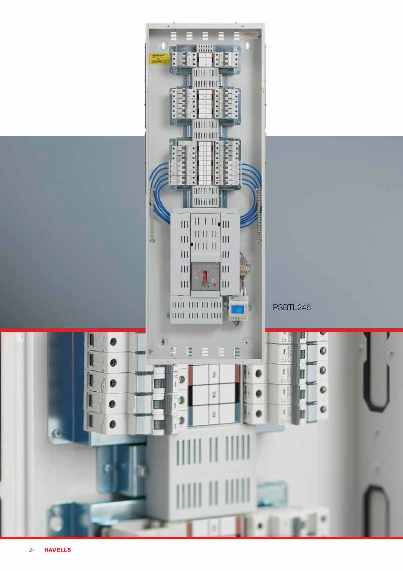
PSBTL246
PowerSafe – Commercial & Industrial 25
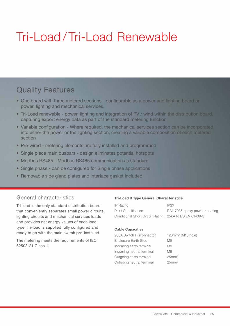
Tri-Load / Tri-Load Renewable
Quality Features• One board with three metered sections - configurable as a power and lighting board or
power, lighting and mechanical services.
• Tri-Load renewable - power, lighting and integration of PV / wind within the distribution board, capturing export energy data as part of the standard metering function
• Variable configuration - Where required, the mechanical services section can be incorporated into either the power or the lighting section, creating a variable composition of each metered section
• Pre-wired - metering elements are fully installed and programmed
• Single piece main busbars - design eliminates potential hotspots
• Modbus RS485 - Modbus RS485 communication as standard
• Single phase - can be configured for Single phase applications
• Removable side gland plates and interface gasket included
General characteristicsTri-load is the only standard distribution board that conveniently separates small power circuits, lighting circuits and mechanical services loads and provides net energy values of each load type. Tri-load is supplied fully configured and ready to go with the main switch pre-installed.
The metering meets the requirements of IEC 62503-21 Class 1.
Tri-Load B Type General Characteristics
IP Rating
Paint Specification
Conditional Short Circuit Rating
IP3X
RAL 7035 epoxy powder coating
25kA to BS EN 61439-3
Cable Capacities
200A Switch Disconnector
Enclosure Earth Stud
Incoming earth terminal
Incoming neutral terminal
Outgoing earth terminal
Outgoing neutral terminal
120mm2 (M10 hole)
M8
M8
M8
25mm2
25mm2
26 HAVELLS
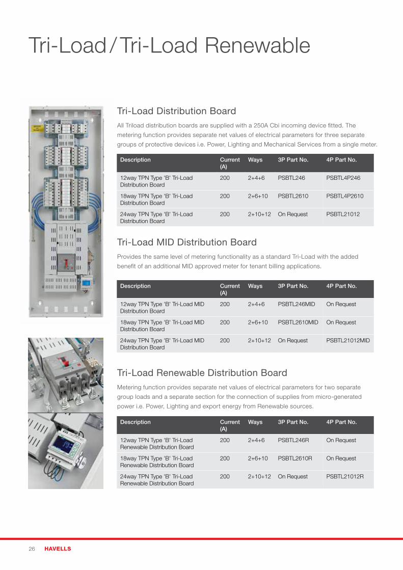
Tri-Load / Tri-Load Renewable
Description Current (A)
Ways 3P Part No. 4P Part No.
12way TPN Type 'B' Tri-Load Distribution Board
200 2+4+6 PSBTL246 PSBTL4P246
18way TPN Type 'B' Tri-Load Distribution Board
200 2+6+10 PSBTL2610 PSBTL4P2610
24way TPN Type 'B' Tri-Load Distribution Board
200 2+10+12 On Request PSBTL21012
Description Current (A)
Ways 3P Part No. 4P Part No.
12way TPN Type 'B' Tri-Load MID Distribution Board
200 2+4+6 PSBTL246MID On Request
18way TPN Type 'B' Tri-Load MID Distribution Board
200 2+6+10 PSBTL2610MID On Request
24way TPN Type 'B' Tri-Load MID Distribution Board
200 2+10+12 On Request PSBTL21012MID
Description Current (A)
Ways 3P Part No. 4P Part No.
12way TPN Type 'B' Tri-Load Renewable Distribution Board
200 2+4+6 PSBTL246R On Request
18way TPN Type 'B' Tri-Load Renewable Distribution Board
200 2+6+10 PSBTL2610R On Request
24way TPN Type 'B' Tri-Load Renewable Distribution Board
200 2+10+12 On Request PSBTL21012R
Tri-Load Distribution BoardAll Triload distribution boards are supplied with a 250A Cbi incoming device fitted. The
metering function provides separate net values of electrical parameters for three separate
groups of protective devices i.e. Power, Lighting and Mechanical Services from a single meter.
Tri-Load MID Distribution BoardProvides the same level of metering functionality as a standard Tri-Load with the added
benefit of an additional MID approved meter for tenant billing applications.
Tri-Load Renewable Distribution BoardMetering function provides separate net values of electrical parameters for two separate
group loads and a separate section for the connection of supplies from micro-generated
power i.e. Power, Lighting and export energy from Renewable sources.
PowerSafe – Commercial & Industrial 27
Surge protection device for Type ‘B’ TPN distribution board For further information on surge protection please refer to pages 62-63. Requires 3P 63A
Type C MCB (please order separately).
Description Part No.
Enclosed surge protection kit - Type I & II* PSB415M1E
*Install on left.
Modular enclosures for Type ‘B’ distribution boards Modular enclosures will accept modular devices including rail mounted meters and
contactors.
Description Part No.
Modular enclosure, 12 module din rail plain door PSME12P
Modular enclosure, 12 module din rail glazed door PSME12G
Modular enclosure, 15 module din rail hinged door PSME15D
Modular enclosure, 30 module din rail hinged door PSME30D
Cable extension boxes for Type ‘B’ distribution boards For requirements where additional space is required for larger cable sizes.
Description Part No.
Cable extension box for Type ‘B’ distribution board 180mm PSBEX180
Cable extension box for Type ‘B’ distribution board 250mm PSBEX250
Outgoing devices - MCBs 10kA, Single Pole Types B, C and D, 10kA to IEC 60898
Description Current (A) Type B Type C Type D
Miniature Circuit Breaker 10kA 1A - PSH101C -
Miniature Circuit Breaker 10kA 2A - PSH102C -
Miniature Circuit Breaker 10kA 4A - PSH104C -
Miniature Circuit Breaker 10kA 6A PSH106B PSH106C PSH106D
Miniature Circuit Breaker 10kA 10A PSH110B PSH110C PSH110D
Miniature Circuit Breaker 10kA 16A PSH116B PSH116C PSH116D
Miniature Circuit Breaker 10kA 20A PSH120B PSH120C PSH120D
Miniature Circuit Breaker 10kA 25A PSH125B PSH125C PSH125D
Miniature Circuit Breaker 10kA 32A PSH132B PSH132C PSH132D
Miniature Circuit Breaker 10kA 40A PSH140B PSH140C -
Miniature Circuit Breaker 10kA 50A PSH150B PSH150C -
Miniature Circuit Breaker 10kA 63A PSH163B PSH163C -
For Type D MCBs above 32A please contact sales office for further details
PSH106C
PSB415M1E*
PSBEX180
PSME15D
28 HAVELLS
PSCP132CR30
PSBIFK
PSBM
Outgoing devices - MCBs 10kA, Triple Pole Types B, C and D, 10kA to IEC 60898
Description Current (A) Type B Type C Type D
Miniature Circuit Breaker 10kA 2A - PSH302C -
Miniature Circuit Breaker 10kA 4A - PSH304C -
Miniature Circuit Breaker 10kA 6A PSH306B PSH306C PSH306D
Miniature Circuit Breaker 10kA 10A PSH310B PSH310C PSH310D
Miniature Circuit Breaker 10kA 16A PSH316B PSH316C PSH316D
Miniature Circuit Breaker 10kA 20A PSH320B PSH320C PSH320D
Miniature Circuit Breaker 10kA 25A PSH325B PSH325C PSH325D
Miniature Circuit Breaker 10kA 32A PSH332B PSH332C PSH332D
Miniature Circuit Breaker 10kA 40A PSH340B PSH340C -
Miniature Circuit Breaker 10kA 50A PSH350B PSH350C -
Miniature Circuit Breaker 10kA 63A PSH363B PSH363C -
For Type D MCBs above 32A please contact sales office for further details
Outgoing devices - RCBOs 10kA Single Pole 30mA Types B and C to IEC/ EN 61009
Description Current (A) Type B Type C
Compact RCBO 10kA - A type 6 PSCP106BR30 PSCP106CR30
Compact RCBO 10kA - A type 10 PSCP110BR30 PSCP110CR30
Compact RCBO 10kA - A type 16 PSCP116BR30 PSCP116CR30
Compact RCBO 10kA - A type 20 PSCP120BR30 PSCP120CR30
Compact RCBO 10kA - A type 32 PSCP132BR30 PSCP132CR30
Standard Size RCBO 10kA - A type 40 PSH140BR30 PSH140CR30
Standard Size RCBO 10kA - A type 50 PSH150BR30 PSH150CR30
General accessories
Description Part No.
MCB Blanking module 18mm PSBM
Universal device lockout attachment - fits MCBs, RCCB & RCBOs PSUDLA
Door barrel lock with 2 keys PSDBL
Top/bottom gland plate PSGP
High integrity/clean earth kit PSCE8
Additional earth bar PSAEB15
Spare way label 12 way - pack of 5 PSLB12
Spare way label 18 way - pack of 5 PSLB18
Spare Interface Kit for Type ‘B’ distribution boards* PSBIFK
Single Phase Kit for Tri-Load and 250A distribution board PSBTL1NK*MCB not included.
PSH332C
PSUDLA*
PowerSafe – Commercial & Industrial 29
Watch our YouTube videos on Tri-Load
simply scan the QR code below
or visit youtube.com/havellsuk
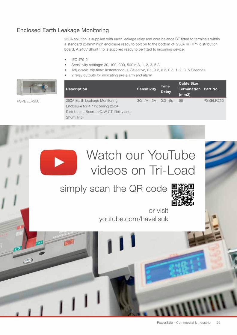
250A solution is supplied with earth leakage relay and core balance CT fitted to terminals within a standard 250mm high enclosure ready to bolt on to the bottom of 250A 4P TPN distribution board. A 240V Shunt trip is supplied ready to be fitted to incoming device.
• IEC 479-2• Sensitivity settings: 30, 100, 300, 500 mA, 1, 2, 3, 5 A• Adjustable trip time: Instantaneous, Selective, 0.1, 0.2, 0.3, 0.5, 1, 2, 3, 5 Seconds• 2 relay outputs for indicating pre-alarm and alarm
Description SensitivityTime
Delay
Cable Size
Termination
(mm2)
Part No.
250A Earth Leakage Monitoring
Enclosure for 4P Incoming 250A
Distribution Boards (C/W CT, Relay and
Shunt Trip)
30m/A - 5A 0.01-5s 95 PSBELR250
Enclosed Earth Leakage Monitoring
PSPBELR250
30 HAVELLS
PowerSafe – Commercial & Industrial 31
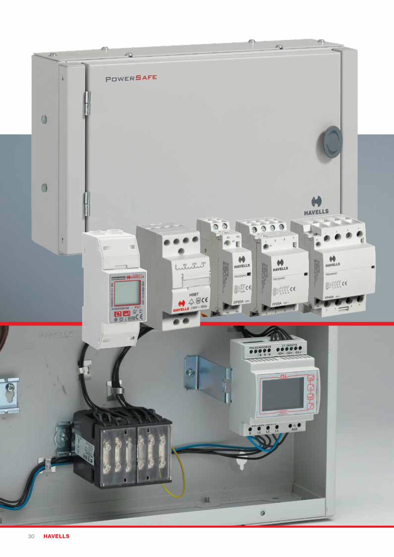
Modular Devices and Enclosures
Quality features• MID Approved meters for energy monitoring and tenant billing applications
• Modular contactors for control of motor, heating and lighting applications
• Digital and Analogue Time Switches for remote command and control of circuits
• Selectable Voltage Bell Transformer
• Modular Enclosures with hinged lockable door for mounting DIN devices
Time Switches
• Analogueanddigitalversionsavailable• Dinrailmountable• Manualoverride• Fullyprogrammable• BelltransformercomplianttoIEC61558-1
MID Meters
• MIDapproval-AnnexB&D• DirectConnectupto100A• SPNandTPNversions• ModbusandPulseOutputsasstandard
Modular Contactors
• AC7AUtilisationCategoryforsmalllighting and heating applications• 2Pand4Pversions• NormallyOpenandClosedoptions
Havells extends its product portfolio with a
complementary range of command and control products
for use in both residual and commercial applications.
The range includes AC7a Modular Contactors up to 63A,
Programmable Time Switches in both analogue and
digital and a selectable voltage bell transformer from
8-16V DC.
32 HAVELLS
Modular Devices and Enclosures
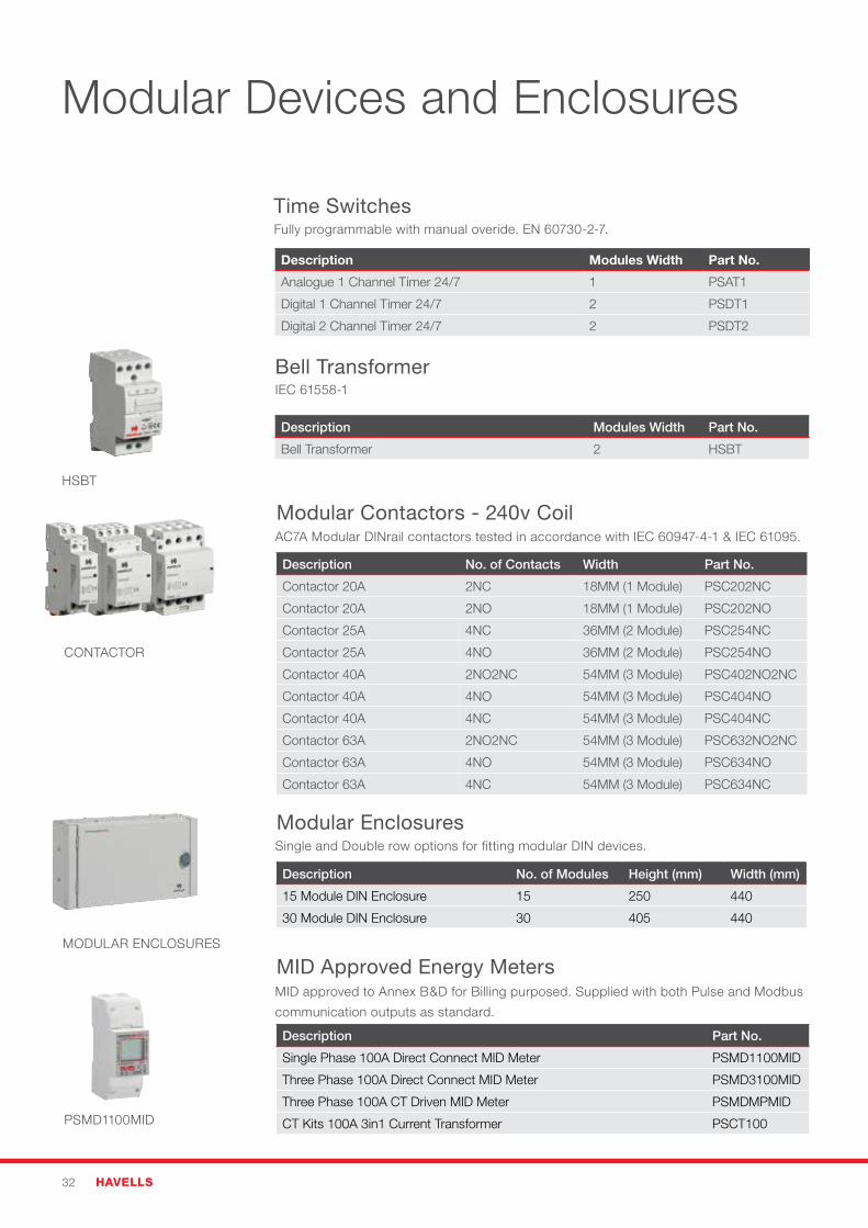
Time Switches
Bell Transformer
Modular Contactors - 240v Coil
HSBT
CONTACTOR
MODULAR ENCLOSURES
PSMD1100MID
Description Modules Width Part No.
Analogue 1 Channel Timer 24/7 1 PSAT1
Digital 1 Channel Timer 24/7 2 PSDT1
Digital 2 Channel Timer 24/7 2 PSDT2
Description Modules Width Part No.
Bell Transformer 2 HSBT
Description No. of Contacts Width Part No.
Contactor 20A 2NC 18MM (1 Module) PSC202NC
Contactor 20A 2NO 18MM (1 Module) PSC202NO
Contactor 25A 4NC 36MM (2 Module) PSC254NC
Contactor 25A 4NO 36MM (2 Module) PSC254NO
Contactor 40A 2NO2NC 54MM (3 Module) PSC402NO2NC
Contactor 40A 4NO 54MM (3 Module) PSC404NO
Contactor 40A 4NC 54MM (3 Module) PSC404NC
Contactor 63A 2NO2NC 54MM (3 Module) PSC632NO2NC
Contactor 63A 4NO 54MM (3 Module) PSC634NO
Contactor 63A 4NC 54MM (3 Module) PSC634NC
Description No. of Modules Height (mm) Width (mm)
15 Module DIN Enclosure 15 250 440
30 Module DIN Enclosure 30 405 440
Description Part No.
Single Phase 100A Direct Connect MID Meter PSMD1100MID
Three Phase 100A Direct Connect MID Meter PSMD3100MID
Three Phase 100A CT Driven MID Meter PSMDMPMID
CT Kits 100A 3in1 Current Transformer PSCT100
Modular Enclosures
MID Approved Energy Meters
Fully programmable with manual overide. EN 60730-2-7.
IEC 61558-1
AC7A Modular DINrail contactors tested in accordance with IEC 60947-4-1 & IEC 61095.
Single and Double row options for fitting modular DIN devices.
MID approved to Annex B&D for Billing purposed. Supplied with both Pulse and Modbus
communication outputs as standard.

PowerSafe – Commercial & Industrial 33
Watch our YouTube installation videos
simply scan the QR code below
or visit youtube.com/havellsuk
34 HAVELLS
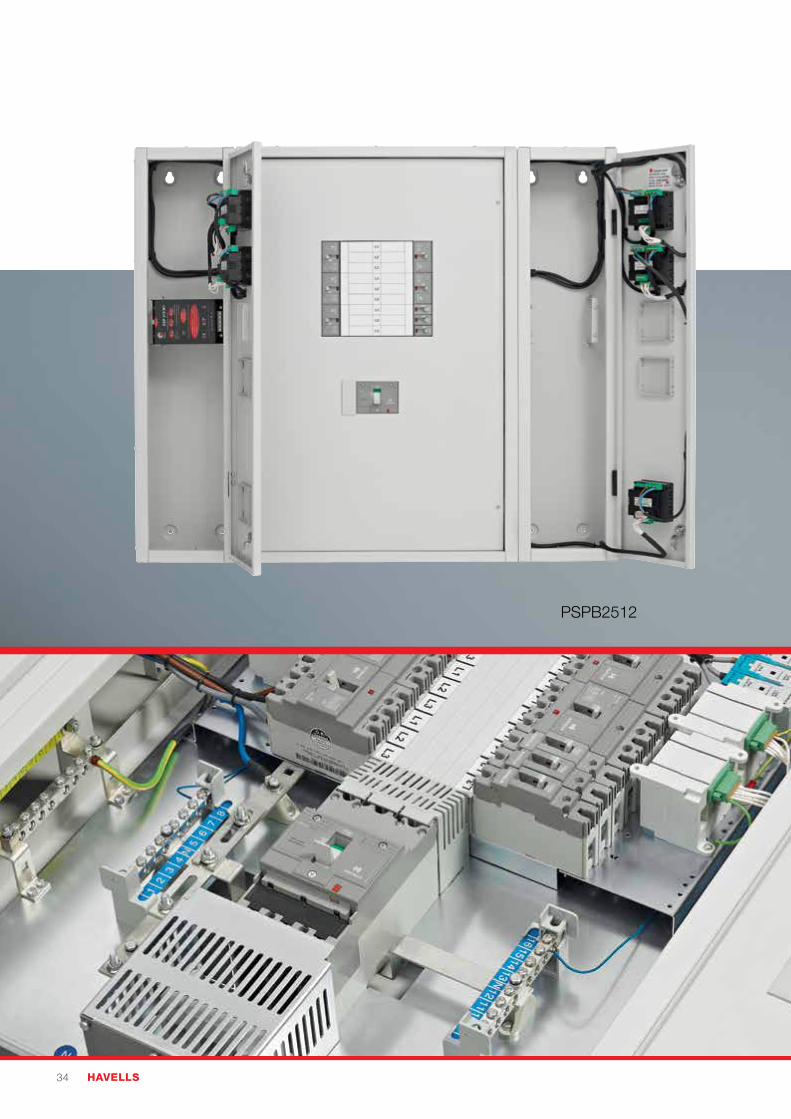
PSPB2512
PowerSafe – Commercial & Industrial 35
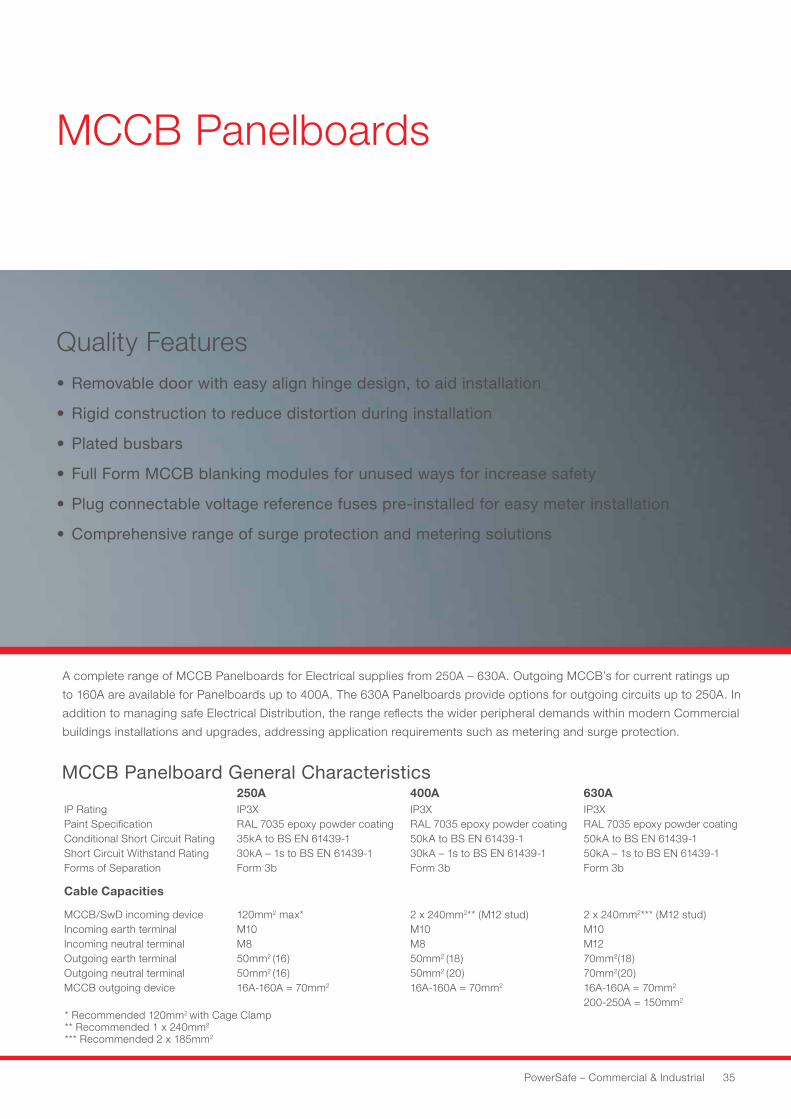
MCCB Panelboards
Quality Features• Removable door with easy align hinge design, to aid installation
• Rigid construction to reduce distortion during installation
• Plated busbars
• Full Form MCCB blanking modules for unused ways for increase safety
• Plug connectable voltage reference fuses pre-installed for easy meter installation
• Comprehensive range of surge protection and metering solutions
MCCB Panelboard General Characteristics250A 400A 630A
IP RatingPaint SpecificationConditional Short Circuit RatingShort Circuit Withstand RatingForms of Separation
IP3XRAL 7035 epoxy powder coating35kA to BS EN 61439-130kA – 1s to BS EN 61439-1Form 3b
IP3XRAL 7035 epoxy powder coating50kA to BS EN 61439-130kA – 1s to BS EN 61439-1Form 3b
IP3XRAL 7035 epoxy powder coating50kA to BS EN 61439-150kA – 1s to BS EN 61439-1Form 3b
Cable Capacities
MCCB/SwD incoming deviceIncoming earth terminalIncoming neutral terminalOutgoing earth terminalOutgoing neutral terminalMCCB outgoing device
120mm2 max*M10M850mm2 (16)50mm2 (16)16A-160A = 70mm2
2 x 240mm2** (M12 stud)M10M850mm2 (18)50mm2 (20)16A-160A = 70mm2
2 x 240mm2*** (M12 stud)M10M1270mm2(18)70mm2(20)16A-160A = 70mm2 200-250A = 150mm2
A complete range of MCCB Panelboards for Electrical supplies from 250A – 630A. Outgoing MCCB’s for current ratings up
to 160A are available for Panelboards up to 400A. The 630A Panelboards provide options for outgoing circuits up to 250A. In
addition to managing safe Electrical Distribution, the range reflects the wider peripheral demands within modern Commercial
buildings installations and upgrades, addressing application requirements such as metering and surge protection.
* Recommended 120mm2 with Cage Clamp** Recommended 1 x 240mm2 *** Recommended 2 x 185mm2
36 HAVELLS
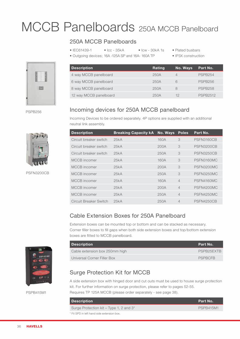
MCCB Panelboards 250A MCCB Panelboard
250A MCCB Panelboards •IEC61439-1 •Icc-35kA •Icw-30kA1s •Platedbusbars
•Outgoingdevices;16A-125ASPand16A-160ATP •IP3Xconstruction
Description Rating No. Ways Part No.
4 way MCCB panelboard 250A 4 PSPB254
6 way MCCB panelboard 250A 6 PSPB256
8 way MCCB panelboard 250A 8 PSPB258
12 way MCCB panelboard 250A 12 PSPB2512
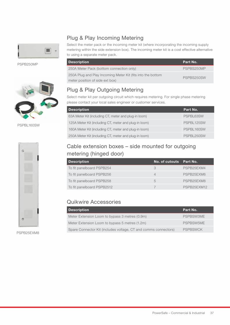
Incoming devices for 250A MCCB panelboard Incoming Devices to be ordered separately. 4P options are supplied with an additional
neutral link assembly.
Description Breaking Capacity kA No. Ways Poles Part No.
Circuit breaker switch 25kA 160A 3 PSFN3160CB
Circuit breaker switch 25kA 200A 3 PSFN3200CB
Circuit breaker switch 25kA 250A 3 PSFN3250CB
MCCB incomer 25kA 160A 3 PSFN3160MC
MCCB incomer 25kA 200A 3 PSFN3200MC
MCCB incomer 25kA 250A 3 PSFN3250MC
MCCB incomer 25kA 160A 4 PSFN4160MC
MCCB incomer 25kA 200A 4 PSFN4200MC
MCCB incomer 25kA 250A 4 PSFN4250MC
Circuit Breaker Switch 25kA 250A 4 PSFN4250CB
Cable Extension Boxes for 250A PanelboardExtension boxes can be mounted top or bottom and can be stacked as necessary.
Corner filler boxes to fill gaps when both side extension boxes and top/bottom extension
boxes are fitted to MCCB panelboard.
Description Part No.
Cable extension box 250mm high PSPB25EXTB
Universal Corner Filler Box PSPBCFB
Surge Protection Kit for MCCBA side extension box with hinged door and cut outs must be used to house surge protection
kit. For further information on surge protection, please refer to pages 52-55.
Requires TP 125A MCCB (please order separately - see page 38).
Description Part No.
Surge Protection kit – Type 1, 2 and 3* PSPB415M1* Fit SPD in left hand side extension box.
PSPB256
PSFN3200CB
PSPB415M1
PowerSafe – Commercial & Industrial 37
Plug & Play Incoming Metering Select the meter pack or the incoming meter kit (where incorporating the incoming supply metering within the side extension box). The incoming meter kit is a cost effective alternative to using a separate meter pack.
Description Part No.
250A Meter Pack (bottom connection only) PSPBS250MP
250A Plug and Play Incoming Meter Kit (fits into the bottom
meter position of side ext box)PSPBS250SW
Plug & Play Outgoing MeteringSelect meter kit per outgoing circuit which requires metering. For single phase metering
please contact your local sales engineer or customer services.
Description Part No.
63A Meter Kit (including CT, meter and plug-in loom) PSPBL63SW
125A Meter Kit (including CT, meter and plug-in loom) PSPBL125SW
160A Meter Kit (including CT, meter and plug-in loom) PSPBL160SW
250A Meter Kit (including CT, meter and plug-in loom) PSPBL250SW
Cable extension boxes – side mounted for outgoing metering (hinged door) Description No. of cutouts Part No.
To fit panelboard PSPB254 3 PSPB25EXM4
To fit panelboard PSPB256 4 PSPB25EXM6
To fit panelboard PSPB258 5 PSPB25EXM8
To fit panelboard PSPB2512 7 PSPB25EXM12
PSPB250MP
PSPBL160SW
PSPB25EXM8
Quikwire Accessories Description Part No.
Meter Extension Loom to bypass 3 metres (0.9m) PSPBSW3ME
Meter Extension Loom to bypass 5 metres (1.2m) PSPBSW5ME
Spare Connector Kit (includes voltage, CT and comms connectors) PSPBSWCK
38 HAVELLS
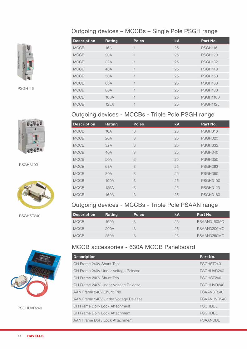
Outgoing devices – MCCBs – Single Pole PSGH range
Description Rating Poles kA Part No.
GH Frame MCCB 16A 1 25 PSGH116
GH Frame MCCB 20A 1 25 PSGH120
GH Frame MCCB 32A 1 25 PSGH132
GH Frame MCCB 40A 1 25 PSGH140
GH Frame MCCB 50A 1 25 PSGH150
GH Frame MCCB 63A 1 25 PSGH163
GH Frame MCCB 80A 1 25 PSGH180
GH Frame MCCB 100A 1 25 PSGH1100
GH Frame MCCB 125A 1 25 PSGH1125
Outgoing devices - MCCBs - Triple Pole PSGH range
Description Rating Poles kA Part No.
GH Frame MCCB 16A 3 25 PSGH316
GH Frame MCCB 20A 3 25 PSGH320
GH Frame MCCB 32A 3 25 PSGH332
GH Frame MCCB 40A 3 25 PSGH340
GH Frame MCCB 50A 3 25 PSGH350
GH Frame MCCB 63A 3 25 PSGH363
GH Frame MCCB 80A 3 25 PSGH380
GH Frame MCCB 100A 3 25 PSGH3100
GH Frame MCCB 125A 3 25 PSGH3125
GH Frame MCCB 160A 3 25 PSGH3160
MCCB accessoriesDescription Part No.
FN Frame 240V Shunt Trip PSFNST240
FN Frame 240V Under Voltage Release PSFNUVR240
GH Frame 240V Shunt Trip PSGHST240
GH Frame 240V Under Voltage Release PSGHUVR240
FN Frame Dolly Lock Attachment PSFNDBL
GH Frame Dolly Lock Attachment PSGHDBL
General accessories
Description Part No.
Single pole PSGH MCCB blanking module (for unused ways) PSPBGH1BM
Barrel door lock with two keys PSPBDLK
Terminal shroud for outgoing MCCB for GH Type 3 Pole PSPBGHTS3
Terminal shroud for outgoing MCCB for GH Type 1 Pole PSPBGHTS1
Blanking module for unused meter cutout PSPB96BM
Neutral and Earth Terminal Extension Kit (Additional 16 neutral and
earth terminals)PSPBNEK
PSPBDLK
PSGH116
PSGH3100
PSGHST240
PSGHUVR240
PowerSafe – Commercial & Industrial 39
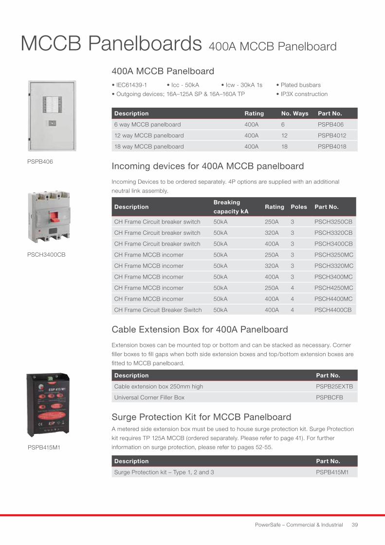
400A MCCB Panelboard •IEC61439-1 •Icc-50kA •Icw-30kA1s •Platedbusbars
•Outgoingdevices;16A–125ASP&16A–160ATP •IP3Xconstruction
Description Rating No. Ways Part No.
6 way MCCB panelboard 400A 6 PSPB406
12 way MCCB panelboard 400A 12 PSPB4012
18 way MCCB panelboard 400A 18 PSPB4018
Incoming devices for 400A MCCB panelboard
Incoming Devices to be ordered separately. 4P options are supplied with an additional
neutral link assembly.
DescriptionBreaking
capacity kARating Poles Part No.
CH Frame Circuit breaker switch 50kA 250A 3 PSCH3250CB
CH Frame Circuit breaker switch 50kA 320A 3 PSCH3320CB
CH Frame Circuit breaker switch 50kA 400A 3 PSCH3400CB
CH Frame MCCB incomer 50kA 250A 3 PSCH3250MC
CH Frame MCCB incomer 50kA 320A 3 PSCH3320MC
CH Frame MCCB incomer 50kA 400A 3 PSCH3400MC
CH Frame MCCB incomer 50kA 250A 4 PSCH4250MC
CH Frame MCCB incomer 50kA 400A 4 PSCH4400MC
CH Frame Circuit Breaker Switch 50kA 400A 4 PSCH4400CB
Cable Extension Box for 400A Panelboard
Extension boxes can be mounted top or bottom and can be stacked as necessary. Corner
filler boxes to fill gaps when both side extension boxes and top/bottom extension boxes are
fitted to MCCB panelboard.
Description Part No.
Cable extension box 250mm high PSPB25EXTB
Universal Corner Filler Box PSPBCFB
Surge Protection Kit for MCCB PanelboardA metered side extension box must be used to house surge protection kit. Surge Protection
kit requires TP 125A MCCB (ordered separately. Please refer to page 41). For further
information on surge protection, please refer to pages 52-55.
Description Part No.
Surge Protection kit – Type 1, 2 and 3 PSPB415M1
MCCB Panelboards 400A MCCB Panelboard
PSPB406
PSPB415M1
PSCH3400CB
40 HAVELLS
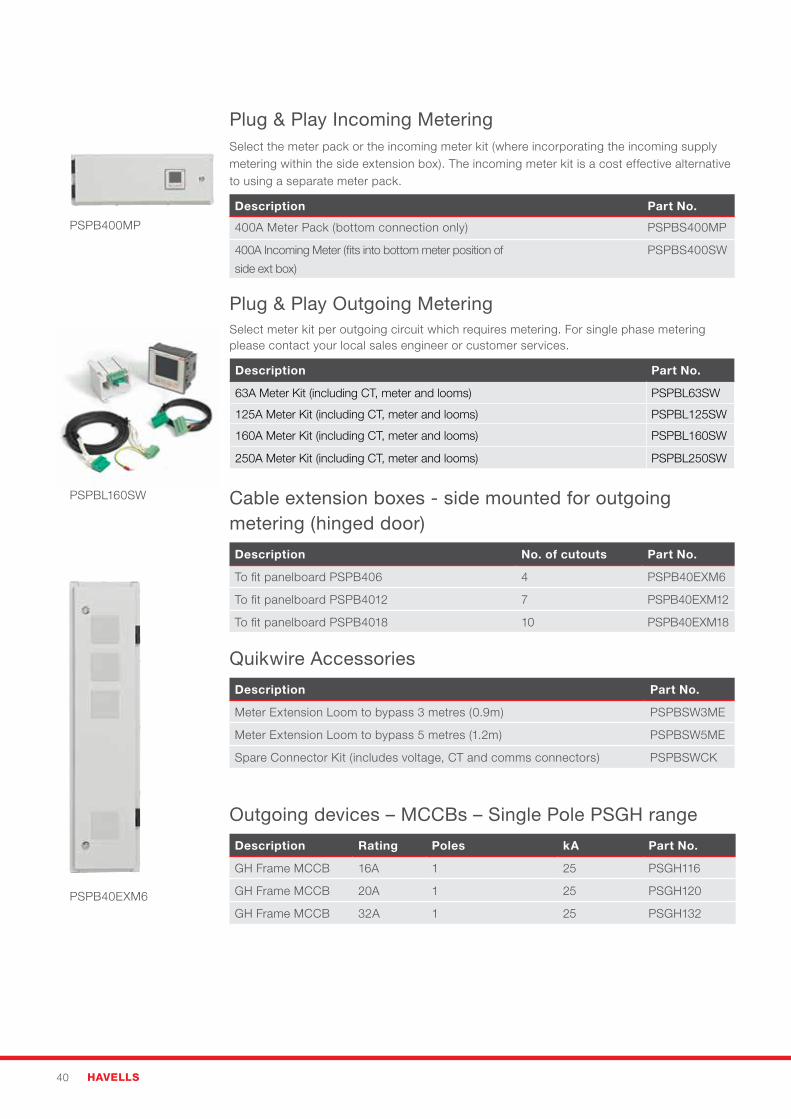
Plug & Play Incoming MeteringSelect the meter pack or the incoming meter kit (where incorporating the incoming supply metering within the side extension box). The incoming meter kit is a cost effective alternative to using a separate meter pack.
Description Part No.
400A Meter Pack (bottom connection only) PSPBS400MP
400A Incoming Meter (fits into bottom meter position of
side ext box)
PSPBS400SW
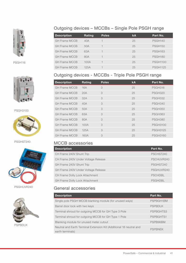
Plug & Play Outgoing MeteringSelect meter kit per outgoing circuit which requires metering. For single phase metering please contact your local sales engineer or customer services.
Description Part No.
63A Meter Kit (including CT, meter and looms) PSPBL63SW
125A Meter Kit (including CT, meter and looms) PSPBL125SW
160A Meter Kit (including CT, meter and looms) PSPBL160SW
250A Meter Kit (including CT, meter and looms) PSPBL250SW
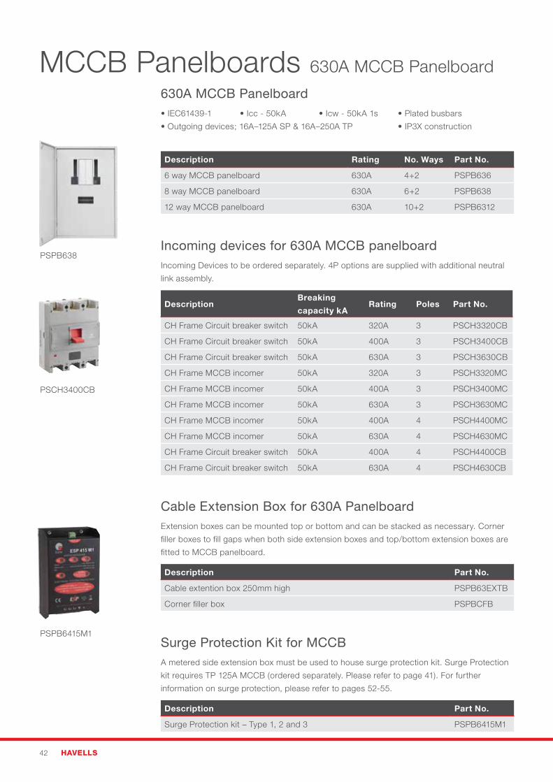
Cable extension boxes - side mounted for outgoing metering (hinged door)
Description No. of cutouts Part No.
To fit panelboard PSPB406 4 PSPB40EXM6
To fit panelboard PSPB4012 7 PSPB40EXM12
To fit panelboard PSPB4018 10 PSPB40EXM18
Quikwire Accessories
Description Part No.
Meter Extension Loom to bypass 3 metres (0.9m) PSPBSW3ME
Meter Extension Loom to bypass 5 metres (1.2m) PSPBSW5ME
Spare Connector Kit (includes voltage, CT and comms connectors) PSPBSWCK
PSPB400MP
PSPBL160SW
PSPB40EXM6
Outgoing devices – MCCBs – Single Pole PSGH range
Description Rating Poles kA Part No.
GH Frame MCCB 16A 1 25 PSGH116
GH Frame MCCB 20A 1 25 PSGH120
GH Frame MCCB 32A 1 25 PSGH132
PowerSafe – Commercial & Industrial 41
Outgoing devices – MCCBs – Single Pole PSGH range
Description Rating Poles kA Part No.
GH Frame MCCB 40A 1 25 PSGH140
GH Frame MCCB 50A 1 25 PSGH150
GH Frame MCCB 63A 1 25 PSGH163
GH Frame MCCB 80A 1 25 PSGH180
GH Frame MCCB 100A 1 25 PSGH1100
GH Frame MCCB 125A 1 25 PSGH1125
Outgoing devices - MCCBs - Triple Pole PSGH range
Description Rating Poles kA Part No.
GH Frame MCCB 16A 3 25 PSGH316
GH Frame MCCB 20A 3 25 PSGH320
GH Frame MCCB 32A 3 25 PSGH332
GH Frame MCCB 40A 3 25 PSGH340
GH Frame MCCB 50A 3 25 PSGH350
GH Frame MCCB 63A 3 25 PSGH363
GH Frame MCCB 80A 3 25 PSGH380
GH Frame MCCB 100A 3 25 PSGH3100
GH Frame MCCB 125A 3 25 PSGH3125
GH Frame MCCB 160A 3 25 PSGH3160
MCCB accessories Description Part No.
CH Frame 240V Shunt Trip PSCHST240
CH Frame 240V Under Voltage Release PSCHUVR240
GH Frame 240V Shunt Trip PSGHST240
GH Frame 240V Under Voltage Release PSGHUVR240
CH Frame Dolly Lock Attachment PSCHDBL
GH Frame Dolly Lock Attachment PSGHDBL
General accessories
Description Part No.
Single pole PSGH MCCB blanking module (for unused ways) PSPBGH1BM
Barrel door lock with two keys PSPBDLK
Terminal shroud for outgoing MCCB for GH Type 3 Pole PSPBGHTS3
Terminal shroud for outgoing MCCB for GH Type 1 Pole PSPBGHTS1
Blanking module for unused meter cutout PSPB96BM
Neutral and Earth Terminal Extension Kit (Additional 16 neutral and
earth terminals)PSPBNEK
PSGH116
PSGH3100
PSGHST240
PSGHUVR240
PSPBDLK
42 HAVELLS
630A MCCB Panelboard •IEC61439-1 •Icc-50kA •Icw-50kA1s •Platedbusbars
•Outgoingdevices;16A–125ASP&16A–250ATP •IP3Xconstruction
Description Rating No. Ways Part No.
6 way MCCB panelboard 630A 4+2 PSPB636
8 way MCCB panelboard 630A 6+2 PSPB638
12 way MCCB panelboard 630A 10+2 PSPB6312
Incoming devices for 630A MCCB panelboard Incoming Devices to be ordered separately. 4P options are supplied with additional neutral
link assembly.
DescriptionBreaking
capacity kARating Poles Part No.
CH Frame Circuit breaker switch 50kA 320A 3 PSCH3320CB
CH Frame Circuit breaker switch 50kA 400A 3 PSCH3400CB
CH Frame Circuit breaker switch 50kA 630A 3 PSCH3630CB
CH Frame MCCB incomer 50kA 320A 3 PSCH3320MC
CH Frame MCCB incomer 50kA 400A 3 PSCH3400MC
CH Frame MCCB incomer 50kA 630A 3 PSCH3630MC
CH Frame MCCB incomer 50kA 400A 4 PSCH4400MC
CH Frame MCCB incomer 50kA 630A 4 PSCH4630MC
CH Frame Circuit breaker switch 50kA 400A 4 PSCH4400CB
CH Frame Circuit breaker switch 50kA 630A 4 PSCH4630CB
Cable Extension Box for 630A PanelboardExtension boxes can be mounted top or bottom and can be stacked as necessary. Corner
filler boxes to fill gaps when both side extension boxes and top/bottom extension boxes are
fitted to MCCB panelboard.
Description Part No.
Cable extention box 250mm high PSPB63EXTB
Corner filler box PSPBCFB
Surge Protection Kit for MCCBA metered side extension box must be used to house surge protection kit. Surge Protection
kit requires TP 125A MCCB (ordered separately. Please refer to page 41). For further
information on surge protection, please refer to pages 52-55.
Description Part No.
Surge Protection kit – Type 1, 2 and 3 PSPB6415M1
MCCB Panelboards 630A MCCB Panelboard
PSPB638
PSPB6415M1
PSCH3400CB
PowerSafe – Commercial & Industrial 43
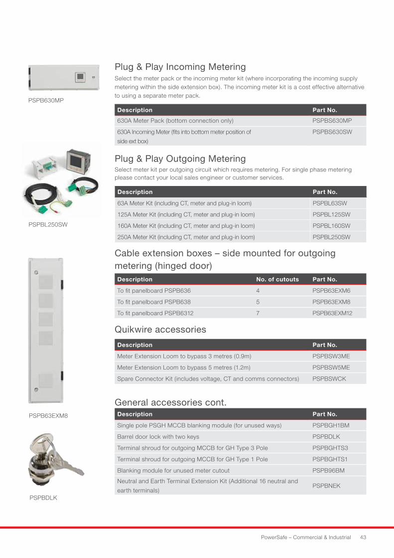
Plug & Play Incoming MeteringSelect the meter pack or the incoming meter kit (where incorporating the incoming supply metering within the side extension box). The incoming meter kit is a cost effective alternative to using a separate meter pack.
Description Part No.
630A Meter Pack (bottom connection only) PSPBS630MP
630A Incoming Meter (fits into bottom meter position of
side ext box)
PSPBS630SW
Plug & Play Outgoing MeteringSelect meter kit per outgoing circuit which requires metering. For single phase metering please contact your local sales engineer or customer services.
Description Part No.
63A Meter Kit (including CT, meter and plug-in loom) PSPBL63SW
125A Meter Kit (including CT, meter and plug-in loom) PSPBL125SW
160A Meter Kit (including CT, meter and plug-in loom) PSPBL160SW
250A Meter Kit (including CT, meter and plug-in loom) PSPBL250SW
Cable extension boxes – side mounted for outgoing metering (hinged door) Description No. of cutouts Part No.
To fit panelboard PSPB636 4 PSPB63EXM6
To fit panelboard PSPB638 5 PSPB63EXM8
To fit panelboard PSPB6312 7 PSPB63EXM12
Quikwire accessories
Description Part No.
Meter Extension Loom to bypass 3 metres (0.9m) PSPBSW3ME
Meter Extension Loom to bypass 5 metres (1.2m) PSPBSW5ME
Spare Connector Kit (includes voltage, CT and comms connectors) PSPBSWCK
PSPB630MP
PSPBL250SW
PSPB63EXM8
General accessories cont.Description Part No.
Single pole PSGH MCCB blanking module (for unused ways) PSPBGH1BM
Barrel door lock with two keys PSPBDLK
Terminal shroud for outgoing MCCB for GH Type 3 Pole PSPBGHTS3
Terminal shroud for outgoing MCCB for GH Type 1 Pole PSPBGHTS1
Blanking module for unused meter cutout PSPB96BM
Neutral and Earth Terminal Extension Kit (Additional 16 neutral and
earth terminals)PSPBNEK
PSPBDLK
44 HAVELLS
Outgoing devices – MCCBs – Single Pole PSGH range
Description Rating Poles kA Part No.
MCCB 16A 1 25 PSGH116
MCCB 20A 1 25 PSGH120
MCCB 32A 1 25 PSGH132
MCCB 40A 1 25 PSGH140
MCCB 50A 1 25 PSGH150
MCCB 63A 1 25 PSGH163
MCCB 80A 1 25 PSGH180
MCCB 100A 1 25 PSGH1100
MCCB 125A 1 25 PSGH1125
Outgoing devices - MCCBs - Triple Pole PSGH range
Description Rating Poles kA Part No.
MCCB 16A 3 25 PSGH316
MCCB 20A 3 25 PSGH320
MCCB 32A 3 25 PSGH332
MCCB 40A 3 25 PSGH340
MCCB 50A 3 25 PSGH350
MCCB 63A 3 25 PSGH363
MCCB 80A 3 25 PSGH380
MCCB 100A 3 25 PSGH3100
MCCB 125A 3 25 PSGH3125
MCCB 160A 3 25 PSGH3160
Outgoing devices - MCCBs - Triple Pole PSAAN range
Description Rating Poles kA Part No.
MCCB 160A 3 25 PSAAN3160MC
MCCB 200A 3 25 PSAAN3200MC
MCCB 250A 3 25 PSAAN3250MC
MCCB accessories - 630A MCCB Panelboard
Description Part No.
CH Frame 240V Shunt Trip PSCHST240
CH Frame 240V Under Voltage Release PSCHUVR240
GH Frame 240V Shunt Trip PSGHST240
GH Frame 240V Under Voltage Release PSGHUVR240
AAN Frame 240V Shunt Trip PSAANST240
AAN Frame 240V Under Voltage Release PSAANUVR240
CH Frame Dolly Lock Attachment PSCHDBL
GH Frame Dolly Lock Attachment PSGHDBL
AAN Frame Dolly Lock Attachment PSAANDBL
PSGH116
PSGH3100
PSGHST240
PSGHUVR240
PowerSafe – Commercial & Industrial 45
PSPBELR2504P
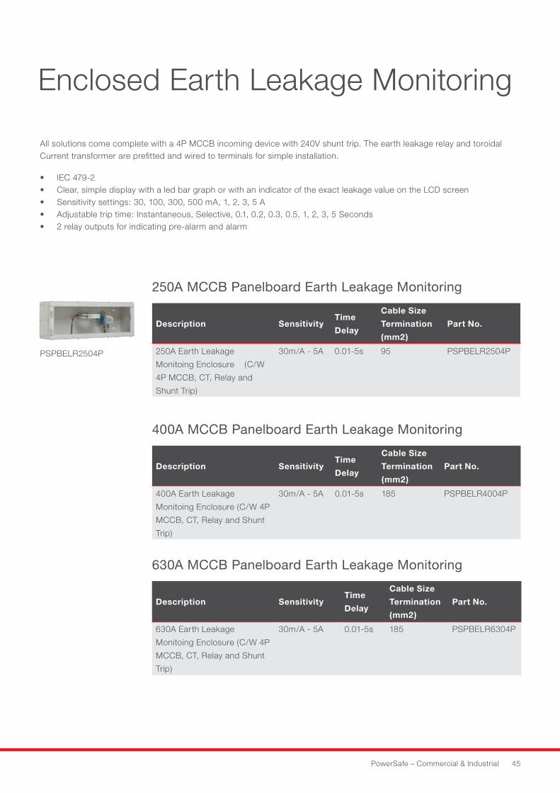
Enclosed Earth Leakage Monitoring
630A MCCB Panelboard Earth Leakage Monitoring
Description SensitivityTime
Delay
Cable Size
Termination
(mm2)
Part No.
630A Earth Leakage
Monitoing Enclosure (C/W 4P
MCCB, CT, Relay and Shunt
Trip)
30m/A - 5A 0.01-5s 185 PSPBELR6304P
400A MCCB Panelboard Earth Leakage Monitoring
Description SensitivityTime
Delay
Cable Size
Termination
(mm2)
Part No.
400A Earth Leakage
Monitoing Enclosure (C/W 4P
MCCB, CT, Relay and Shunt
Trip)
30m/A - 5A 0.01-5s 185 PSPBELR4004P
250A MCCB Panelboard Earth Leakage Monitoring
Description SensitivityTime
Delay
Cable Size
Termination
(mm2)
Part No.
250A Earth Leakage
Monitoing Enclosure (C/W
4P MCCB, CT, Relay and
Shunt Trip)
30m/A - 5A 0.01-5s 95 PSPBELR2504P
All solutions come complete with a 4P MCCB incoming device with 240V shunt trip. The earth leakage relay and toroidal Current transformer are prefitted and wired to terminals for simple installation.
• IEC 479-2• Clear, simple display with a led bar graph or with an indicator of the exact leakage value on the LCD screen• Sensitivity settings: 30, 100, 300, 500 mA, 1, 2, 3, 5 A• Adjustable trip time: Instantaneous, Selective, 0.1, 0.2, 0.3, 0.5, 1, 2, 3, 5 Seconds• 2 relay outputs for indicating pre-alarm and alarm
46 HAVELLS
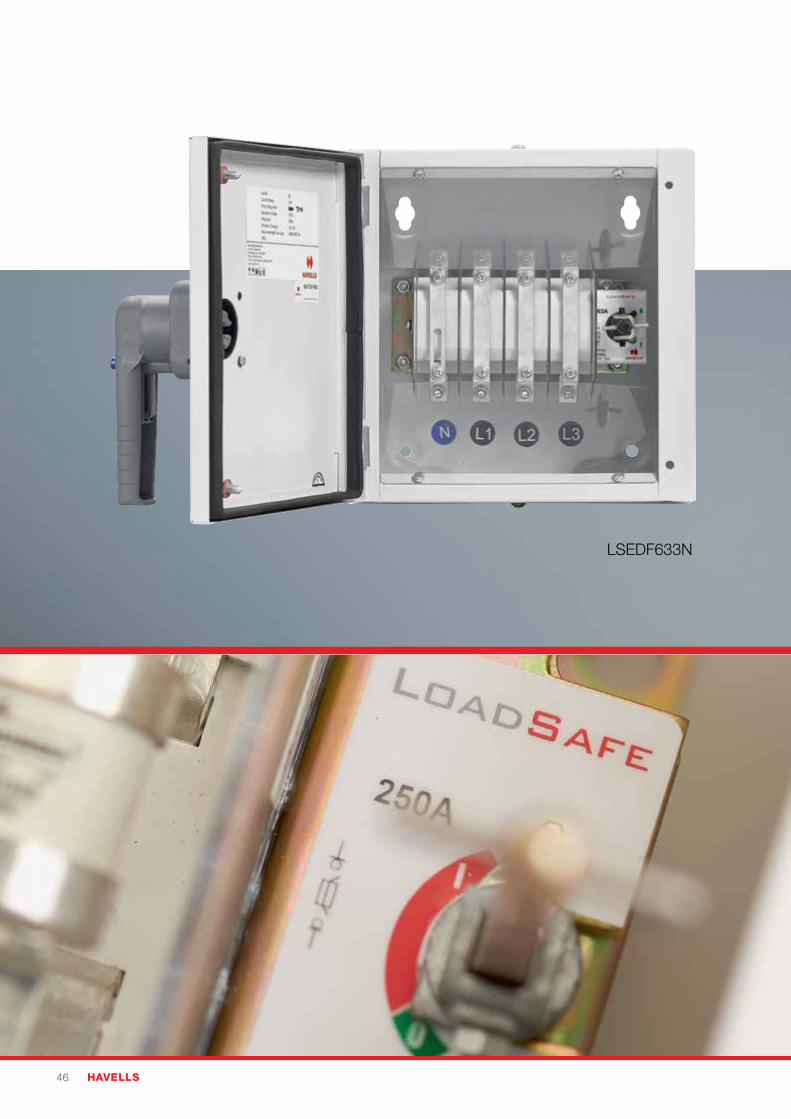
LSEDF633N
PowerSafe – Commercial & Industrial 47
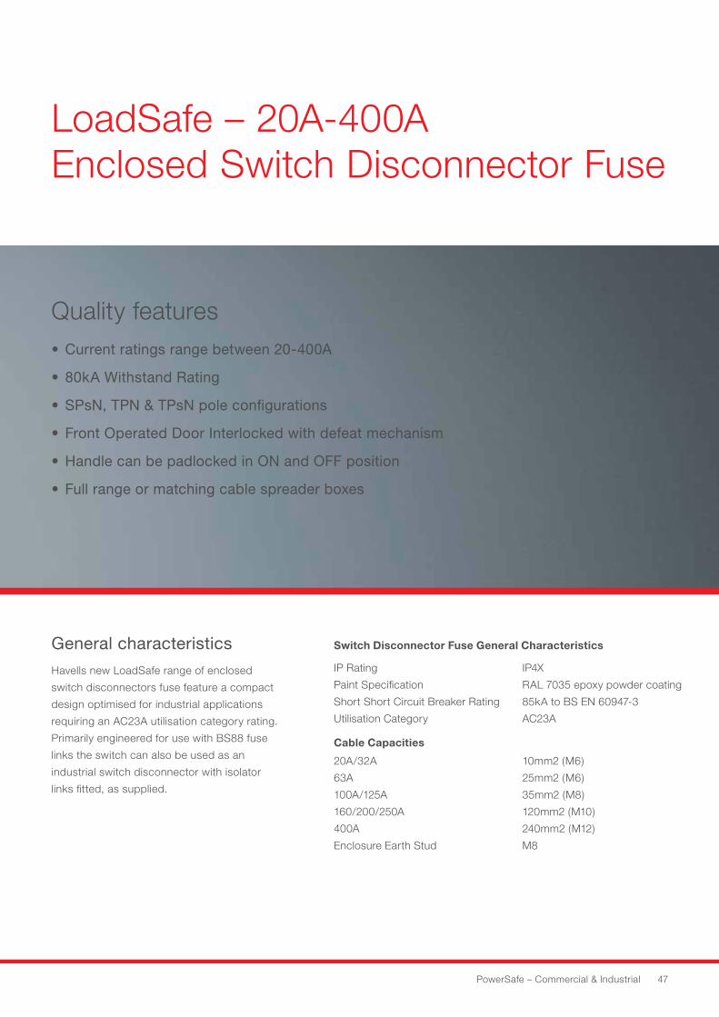
LoadSafe – 20A-400A Enclosed Switch Disconnector Fuse
Quality features• Current ratings range between 20-400A
• 80kA Withstand Rating
• SPsN, TPN & TPsN pole configurations
• Front Operated Door Interlocked with defeat mechanism
• Handle can be padlocked in ON and OFF position
• Full range or matching cable spreader boxes
Havells new LoadSafe range of enclosed
switch disconnectors fuse feature a compact
design optimised for industrial applications
requiring an AC23A utilisation category rating.
Primarily engineered for use with BS88 fuse
links the switch can also be used as an
industrial switch disconnector with isolator
links fitted, as supplied.
General characteristics Switch Disconnector Fuse General Characteristics
IP Rating
Paint Specification
Short Short Circuit Breaker Rating
Utilisation Category
IP4X
RAL 7035 epoxy powder coating
85kA to BS EN 60947-3
AC23A
Cable Capacities
20A/32A
63A
100A/125A
160/200/250A
400A
Enclosure Earth Stud
10mm2 (M6)
25mm2 (M6)
35mm2 (M8)
120mm2 (M10)
240mm2 (M12)
M8
48 HAVELLS
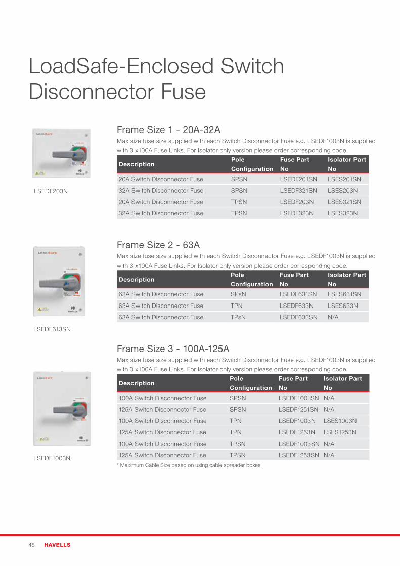
Frame Size 1 - 20A-32AMax size fuse size supplied with each Switch Disconnector Fuse e.g. LSEDF1003N is supplied
with 3 x100A Fuse Links. For Isolator only version please order corresponding code.
DescriptionPole
Configuration
Fuse Part
No
Isolator Part
No
20A Switch Disconnector Fuse SPSN LSEDF201SN LSES201SN
32A Switch Disconnector Fuse SPSN LSEDF321SN LSES203N
20A Switch Disconnector Fuse TPSN LSEDF203N LSES321SN
32A Switch Disconnector Fuse TPSN LSEDF323N LSES323N
Frame Size 2 - 63AMax size fuse size supplied with each Switch Disconnector Fuse e.g. LSEDF1003N is supplied
with 3 x100A Fuse Links. For Isolator only version please order corresponding code.
DescriptionPole
Configuration
Fuse Part
No
Isolator Part
No
63A Switch Disconnector Fuse SPsN LSEDF631SN LSES631SN
63A Switch Disconnector Fuse TPN LSEDF633N LSES633N
63A Switch Disconnector Fuse TPsN LSEDF633SN N/A
Frame Size 3 - 100A-125AMax size fuse size supplied with each Switch Disconnector Fuse e.g. LSEDF1003N is supplied
with 3 x100A Fuse Links. For Isolator only version please order corresponding code.
DescriptionPole
Configuration
Fuse Part
No
Isolator Part
No
100A Switch Disconnector Fuse SPSN LSEDF1001SN N/A
125A Switch Disconnector Fuse SPSN LSEDF1251SN N/A
100A Switch Disconnector Fuse TPN LSEDF1003N LSES1003N
125A Switch Disconnector Fuse TPN LSEDF1253N LSES1253N
100A Switch Disconnector Fuse TPSN LSEDF1003SN N/A
125A Switch Disconnector Fuse TPSN LSEDF1253SN N/A
* Maximum Cable Size based on using cable spreader boxes
LSEDF203N
LSEDF613SN
LSEDF1003N
LoadSafe-Enclosed Switch Disconnector Fuse
PowerSafe – Commercial & Industrial 49
LSEDF4003N
LSEDF1603N
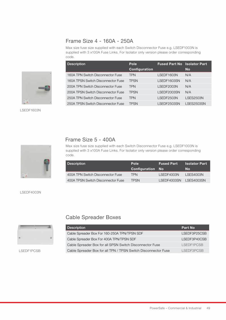
Frame Size 4 - 160A - 250A
Frame Size 5 - 400A
Cable Spreader Boxes
LSEDF1PCSB
Description Pole
Configuration
Fused Part No Isolator Part
No
160A TPN Switch Disconnector Fuse TPN LSEDF1603N N/A
160A TPSN Switch Disconnector Fuse TPSN LSEDF1603SN N/A
200A TPN Switch Disconnector Fuse TPN LSEDF2003N N/A
200A TPSN Switch Disconnector Fuse TPSN LSEDF2003SN N/A
250A TPN Switch Disconnector Fuse TPN LSEDF2503N LSES2503N
250A TPSN Switch Disconnector Fuse TPSN LSEDF2503SN LSES2503SN
Description Pole
Configuration
Fused Part
No
Isolator Part
No
400A TPN Switch Disconnector Fuse TPN LSEDF4003N LSES4003N
400A TPSN Switch Disconnector Fuse TPSN LSEDF4003SN LSES4003SN
Description Part No
Cable Spreader Box For 160-250A TPN/TPSN SDF LSEDF3P25CSB
Cable Spreader Box For 400A TPN/TPSN SDF LSEDF3P40CSB
Cable Spreader Box for all SPSN Switch Disconnector Fuse LSEDF1PCSB
Cable Spreader Box for all TPN / TPSN Switch Disconnector Fuse LSEDF3PCSB
Max size fuse size supplied with each Switch Disconnector Fuse e.g. LSEDF1003N is supplied with 3 x100A Fuse Links. For Isolator only version please order corresponding code.
Max size fuse size supplied with each Switch Disconnector Fuse e.g. LSEDF1003N is supplied with 3 x100A Fuse Links. For Isolator only version please order corresponding code.
50 HAVELLS
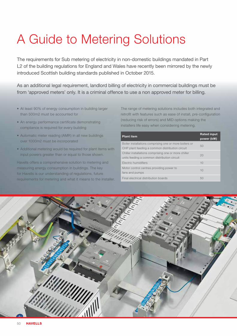
•Atleast90%ofenergyconsumptioninbuildinglarger
than 500m2 must be accounted for
•Anenergyperformancecertificatedemonstrating
compliance is required for every building
•Automaticmeterreading(AMR)inallnewbuildings
over 1000m2 must be incorporated
•Additionalmeteringwouldberequiredforplantitemswith
input powers greater than or equal to those shown.
Havells offers a comprehensive solution to metering and
measuring energy consumption in buildings. The key
for Havells is our understanding of regulations, future
requirements for metering and what it means to the installer.
The range of metering solutions includes both integrated and
retrofit with features such as ease of install, pre-configuration
(reducing risk of errors) and MID options making the
installers life easy when considering metering.
The requirements for Sub metering of electricity in non-domestic buildings mandated in Part L2 of the building regulations for England and Wales have recently been mirrored by the newly introduced Scottish building standards published in October 2015.
As an additional legal requirement, landlord billing of electricity in commercial buildings must be from ‘approved meters’ only. It is a criminal offence to use a non approved meter for billing.
A Guide to Metering Solutions
Plant itemRated input
power (kW)
Boiler installations comprising one or more boilers or
CHP plant feeding a common distribution circuit50
Chiller installations comprising one or more chiller
units feeding a common distribution circuit20
Electric humidifiers 10
Motor control centres providing power to
fans and pumps10
Final electrical distribution boards 50
PowerSafe – Commercial & Industrial 51
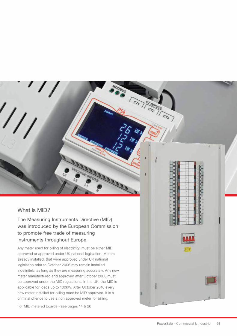
What is MID?
The Measuring Instruments Directive (MID) was introduced by the European Commission to promote free trade of measuring instruments throughout Europe.
Any meter used for billing of electricity, must be either MID
approved or approved under UK national legislation. Meters
already installed, that were approved under UK national
legislation prior to October 2006 may remain installed
indefinitely, as long as they are measuring accurately. Any new
meter manufactured and approved after October 2006 must
be approved under the MID regulations. In the UK, the MID is
applicable for loads up to 100kW. After October 2016 every
new meter installed for billing must be MID approved. It is a
criminal offence to use a non approved meter for billing.
For MID metered boards - see pages 14 & 26
52 HAVELLS
Havells and Furse®
Furse® is a world leader in the design, manufacture and supply of earthing and lightning protection systems.
A Havells / Furse® strategic alliance offers fully type tested
solutions of complete assemblies, including Type A/B
distribution boards and MCCB panel boards. This concept
is unique to the current selection of surge protection devices
within an electrical system as a proven level of energy let
through voltage can be confirmed for a complete assembly
and not simply sub components. (certificates can be found
in our technical section).
The configuration of surge protection devices within each
assembly has been standardised to reduce installation
variables to ensure that a surge protection devices operates
at optimum performance maintaining the integrity of the
electrical system.
•FullytypetestedsolutionsvalidatedbyFurse®
(Thomas and Betts).
•Standardisedkitstoreduceinstallationvariablesfor
optimum performance.
•CompliancetoBSEN62305andIETWiringRegulations,
BS 7671:2008 (+A1:2011).
A Guide to Surge Protection
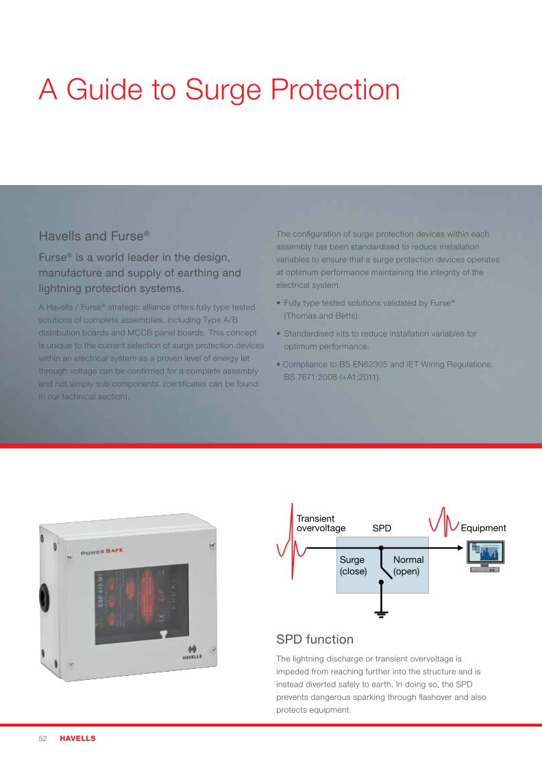
Transientovervoltage SPD
Surge(close)
Normal(open)
Equipment
SPD functionThe lightning discharge or transient overvoltage is
impeded from reaching further into the structure and is
instead diverted safely to earth. In doing so, the SPD
prevents dangerous sparking through flashover and also
protects equipment.
PowerSafe – Commercial & Industrial 53
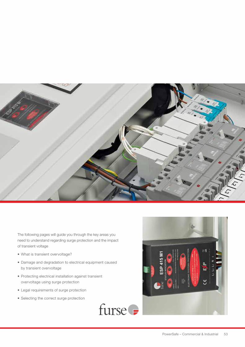
The following pages will guide you through the key areas you
need to understand regarding surge protection and the impact
of transient voltage
• Whatistransientovervoltage?
•Damageanddegradationtoelectricalequipmentcaused
by transient overvoltage
• Protectingelectricalinstallationagainsttransient
overvoltage using surge protection
• Legalrequirementsofsurgeprotection
• Selectingthecorrectsurgeprotection
54 HAVELLS
Sensitive and critical equipment connected to the
electrical system must be protected against transient
overvoltages in accordance with BS EN 62305 and the
latest amendment to the IET Wiring Regulations,
BS 7671:2008 (+A1:2011).
Transient overvoltages are short duration, high magnitude
voltage peaks with fast rising edges, often described as a
‘spike’ or a ‘surge’, which can reach up to 6kV in a well-
insulated power distribution system (see Figure 1).
They are mostly caused by:
• Indirectlightningactivity(upto1kmaway),whichcan
enter a building via connected metallic service lines
through resistive or inductive coupling (see Figures 2
and 3),
• Theelectricalswitchingoflargeinductiveloads(e.g.air
conditioning units, lifts and transformers) within buildings,
or
• Directlightningstrikes,wherepartiallightningcurrents
in an external lightning protection system (LPS) or other
conductive parts attempts to flash over to internal metallic
installations
Transient overvoltages degrade and damage electronic
systems, leading to disruption, expensive downtime and fire/
electric shock hazard.
This can have severe consequences to life, to commercial
& industrial activity, and to the provision of critical
public services.
Degradation of Electrical equipment in the building, by
transient overvoltages begins from the point that the
susceptibility level of electrical equipment is exceeded (if
unknown, calculated as twice the peak operating voltage of
the electrical system, approximately 715V for 230V supplies).
Transient overvoltages affecting equipment susceptibility
occur on the active conductors, i.e. between phase and
neutral in the electrical system.
Outright damage is caused when transient overvoltages
exceed the equipment’s withstand voltage, typically 1.5kV
for sensitive equipment such as computers etc. The transient
overvoltages occur between the active conductors and the
protective conductor, i.e. phase/neutral to PE.
Transient overvoltage protection
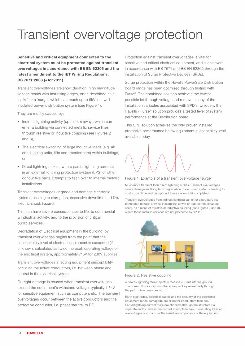
Figure 1: Example of a transient overvoltage ‘surge’
Much more frequent than direct lightning strikes, transient overvoltages cause damage and long term degradation of electronic systems, leading to costly downtime and disruption if these systems fail completely.
Transient overvoltages from indirect lightning can enter a structure via connected metallic service lines (mains power or data communications lines), as a result of resistive or inductive coupling (see Figures 2 and 3), where these metallic services are not protected by SPDs.
Figure 2: Resistive coupling
A nearby lightning strike injects a massive current into the ground. The current flows away from the strike point – preferentially through the path of least resistance.
Earth electrodes, electrical cables and the circuitry of the electronic equipment (once damaged), are all better conductors than soil. Partial lightning current therefore channels through the structure via separate earths, and as the current attempts to flow, devastating transient overvoltages occur across the sensitive components of the equipment.
Protection against transient overvoltages is vital for
sensitive and critical electrical equipment, and is achieved
in accordance with BS 7671 and BS EN 62305 through the
installation of Surge Protective Devices (SPDs).
Surge protection within the Havells PowerSafe Distribution
board range has been optimized through testing with
Furse®. The combined solution achieves the lowest
possible let through voltage and removes many of the
installation variables associated with SPD’s. Uniquely, the
Havells / Furse® solution provides a tested level of system
performance at the Distribution board.
This SPD solution achieves the only proven installed
protective performance below equipment susceptibility level
available today.
PowerSafe – Commercial & Industrial 55
Protecting electrical installations against transient overvoltages using SPDsBritish Standard BS EN 62305:2011 Protection against
lightning and the IET Wiring Regulations 17th Edition, BS
7671:2008 (+A1:2011) define requirements for selection and
installation of SPDs to protect against transient overvoltage
risk.
SPDs are recommended as follows, according to the
installation:
• Lightningcurrent/equipotentialbondingSPDs(Type1
or Combined Type 1+2) to protect against flashover –
required on incoming/outgoing metallic service lines
which have ‘live cores’ if a building includes an external
LPS or overhead service lines at risk from a direct
lightning strike
• TransientovervoltageSPDs(Type2/Type3orCombined
Type 2+3) to protect against transient overvoltages
caused by indirect lightning strikes and switching events
For either Type, the function of the SPD is to limit transient
overvoltages to a safe level by diverting excess energy either
to earth or away from the sensitive and critical electrical
equipment (see Figure 4).
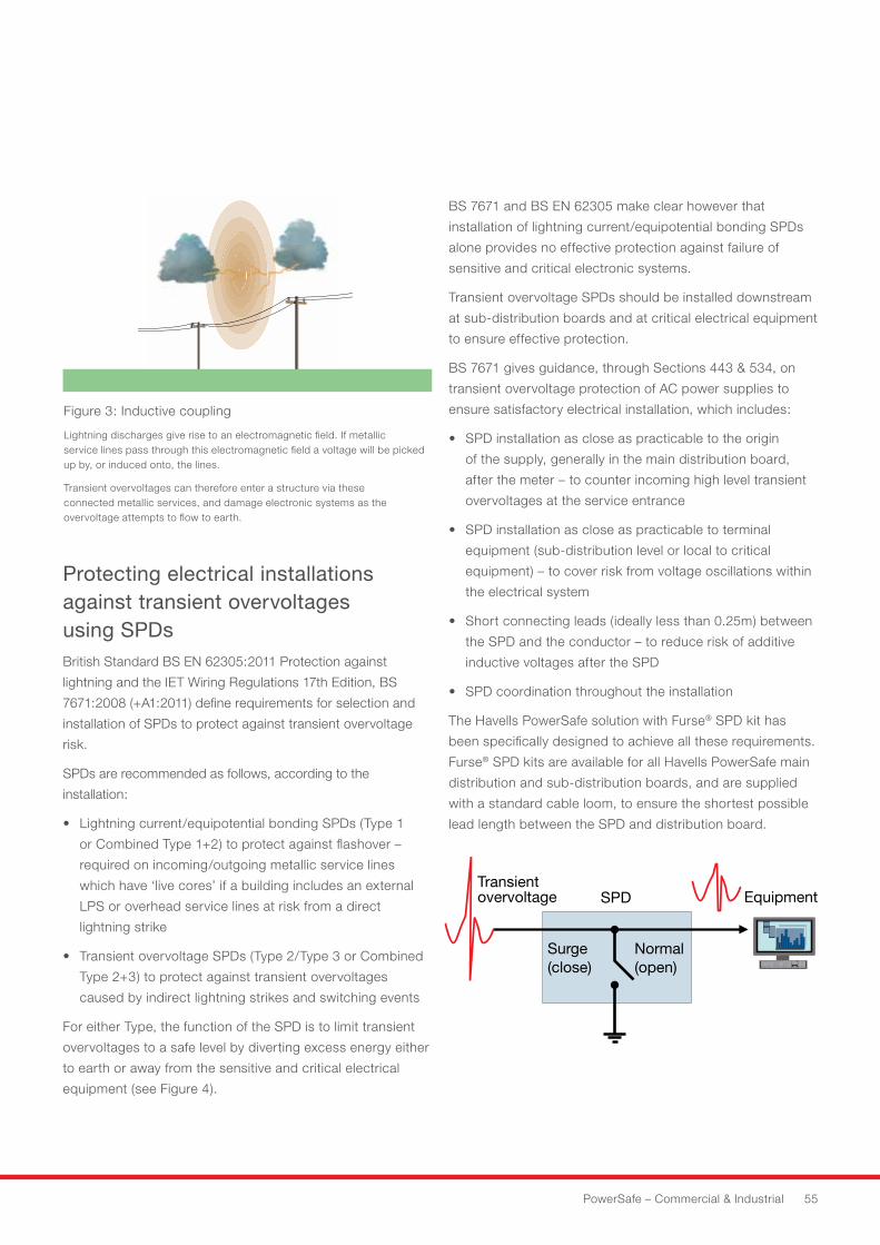
Transientovervoltage SPD
Surge(close)
Normal(open)
Equipment
Figure 3: Inductive coupling
Lightning discharges give rise to an electromagnetic field. If metallic service lines pass through this electromagnetic field a voltage will be picked up by, or induced onto, the lines.
Transient overvoltages can therefore enter a structure via these connected metallic services, and damage electronic systems as the overvoltage attempts to flow to earth.
BS 7671 and BS EN 62305 make clear however that
installation of lightning current/equipotential bonding SPDs
alone provides no effective protection against failure of
sensitive and critical electronic systems.
Transient overvoltage SPDs should be installed downstream
at sub-distribution boards and at critical electrical equipment
to ensure effective protection.
BS 7671 gives guidance, through Sections 443 & 534, on
transient overvoltage protection of AC power supplies to
ensure satisfactory electrical installation, which includes:
• SPDinstallationascloseaspracticabletotheorigin
of the supply, generally in the main distribution board,
after the meter – to counter incoming high level transient
overvoltages at the service entrance
• SPDinstallationascloseaspracticabletoterminal
equipment (sub-distribution level or local to critical
equipment) – to cover risk from voltage oscillations within
the electrical system
• Shortconnectingleads(ideallylessthan0.25m)between
the SPD and the conductor – to reduce risk of additive
inductive voltages after the SPD
• SPDcoordinationthroughouttheinstallation
The Havells PowerSafe solution with Furse® SPD kit has
been specifically designed to achieve all these requirements.
Furse® SPD kits are available for all Havells PowerSafe main
distribution and sub-distribution boards, and are supplied
with a standard cable loom, to ensure the shortest possible
lead length between the SPD and distribution board.
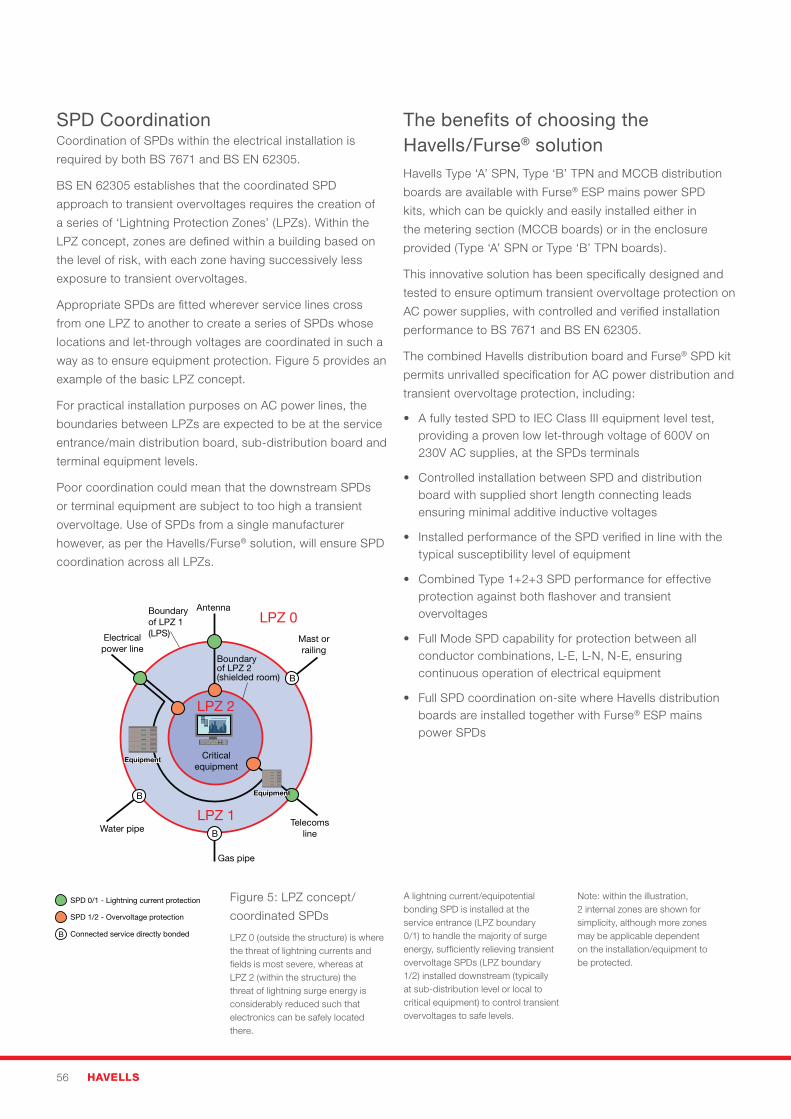
56 HAVELLS
SPD CoordinationCoordination of SPDs within the electrical installation is
required by both BS 7671 and BS EN 62305.
BS EN 62305 establishes that the coordinated SPD
approach to transient overvoltages requires the creation of
a series of ‘Lightning Protection Zones’ (LPZs). Within the
LPZ concept, zones are defined within a building based on
the level of risk, with each zone having successively less
exposure to transient overvoltages.
Appropriate SPDs are fitted wherever service lines cross
from one LPZ to another to create a series of SPDs whose
locations and let-through voltages are coordinated in such a
way as to ensure equipment protection. Figure 5 provides an
example of the basic LPZ concept.
For practical installation purposes on AC power lines, the
boundaries between LPZs are expected to be at the service
entrance/main distribution board, sub-distribution board and
terminal equipment levels.
Poor coordination could mean that the downstream SPDs
or terminal equipment are subject to too high a transient
overvoltage. Use of SPDs from a single manufacturer
however, as per the Havells/Furse® solution, will ensure SPD
coordination across all LPZs.
Boundary of LPZ 2(shielded room)
Boundaryof LPZ 1(LPS)
Antenna
Electricalpower line
Water pipe
Gas pipe
Telecomsline
Mast orrailing
LPZ 2
B
B
B
B
LPZ 1
Criticalequipment
Equipment
SPD 1/2 - Overvoltage protection
Connected service directly bonded
SPD 0/1 - Lightning current protection
Equipment
LPZ 0
Figure 5: LPZ concept/
coordinated SPDs
LPZ 0 (outside the structure) is where the threat of lightning currents and fields is most severe, whereas at LPZ 2 (within the structure) the threat of lightning surge energy is considerably reduced such that electronics can be safely located there.
A lightning current/equipotential bonding SPD is installed at the service entrance (LPZ boundary 0/1) to handle the majority of surge energy, sufficiently relieving transient overvoltage SPDs (LPZ boundary 1/2) installed downstream (typically at sub-distribution level or local to critical equipment) to control transient overvoltages to safe levels.
Note: within the illustration, 2 internal zones are shown for simplicity, although more zones may be applicable dependent on the installation/equipment to be protected.
The benefits of choosing the Havells/Furse® solutionHavells Type ‘A’ SPN, Type ‘B’ TPN and MCCB distribution
boards are available with Furse® ESP mains power SPD
kits, which can be quickly and easily installed either in
the metering section (MCCB boards) or in the enclosure
provided (Type ‘A’ SPN or Type ‘B’ TPN boards).
This innovative solution has been specifically designed and
tested to ensure optimum transient overvoltage protection on
AC power supplies, with controlled and verified installation
performance to BS 7671 and BS EN 62305.
The combined Havells distribution board and Furse® SPD kit
permits unrivalled specification for AC power distribution and
transient overvoltage protection, including:
• AfullytestedSPDtoIECClassIIIequipmentleveltest,providing a proven low let-through voltage of 600V on 230V AC supplies, at the SPDs terminals
• ControlledinstallationbetweenSPDanddistributionboard with supplied short length connecting leads ensuring minimal additive inductive voltages
• InstalledperformanceoftheSPDverifiedinlinewiththetypical susceptibility level of equipment
• CombinedType1+2+3SPDperformanceforeffectiveprotection against both flashover and transient overvoltages
• FullModeSPDcapabilityforprotectionbetweenallconductor combinations, L-E, L-N, N-E, ensuring continuous operation of electrical equipment
• FullSPDcoordinationon-sitewhereHavellsdistributionboards are installed together with Furse® ESP mains power SPDs
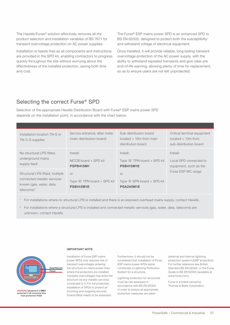
PowerSafe – Commercial & Industrial 57
The Havells/Furse® solution effectively removes all the product selection and installation variables of BS 7671 for transient overvoltage protection on AC power supplies.
Installation is hassle-free as all components and instructions are provided in the SPD kit, enabling contractors to progress quickly throughout the site without worrying about the effectiveness of the installed protection, saving both time and cost.
The Furse® ESP mains power SPD is an enhanced SPD to BS EN 62305, designed to protect both the susceptibility and withstand voltage of electrical equipment.
Once installed, it will provide reliable, long lasting transient overvoltage protection of the AC power supply, with the ability to withstand repeated transients and give clear pre end-of-life warning, allowing plenty of time for replacement, so as to ensure users are not left unprotected.
Installation location TN-S or
TN-C-S supplies
Service entrance, after meter
(main distribution board)
Sub-distribution board
located > 10m from main
distribution board
Critical terminal equipment
located > 10m from
sub-distribution board
No structural LPS fitted,
underground mains
supply feed1
Install:
MCCB board + SPD kit
PSPB415M1
or
Type ‘B’ TPN board + SPD kit
PSB415M1E
Install:
Type ‘B’ TPN board + SPD kit
PSB415M1E
or
Type ‘A’ SPN board + SPD kit
PSA240M1E
Install:
Local SPD connected to
equipment, such as the
Furse ESP MC rangeStructural LPS fitted, multiple
connected metallic services
known (gas, water, data,
telecoms)2
1. For installations where no structural LPS is installed and there is an exposed overhead mains supply, contact Havells.
2. For installations where a structural LPS is installed and connected metallic services (gas, water, data, telecoms) are
unknown, contact Havells.
Installation of Furse ESP mains power SPDs only reduces risk of transient overvoltages entering the structure on mains power lines where the protectors are installed. Transient overvoltages may enter the structure via any metallic services connected to it. For full protection, installation of SPDs to protect all incoming and outgoing services (mains/data) needs to be assessed.
Furthermore, it should not be considered that installation of Furse ESP mains power SPDs alone constitutes a Lightning Protection System for a structure.
Lightning protection for structures must be risk assessed in accordance with BS EN 62305 in order to ensure all appropriate protection measures are taken
(external and internal lightning protection system/LEMP protection). For further reference see British Standard BS EN 62305, or the Furse Guide to BS EN 62305 (available at www.furse.com).
Furse is a brand owned by Thomas & Betts Corporation.
Selecting the correct Furse® SPDSelection of the appropriate Havells Distribution Board with Furse® ESP mains power SPD
depends on the installation point, in accordance with the chart below:
IMPORTANT NOTE:
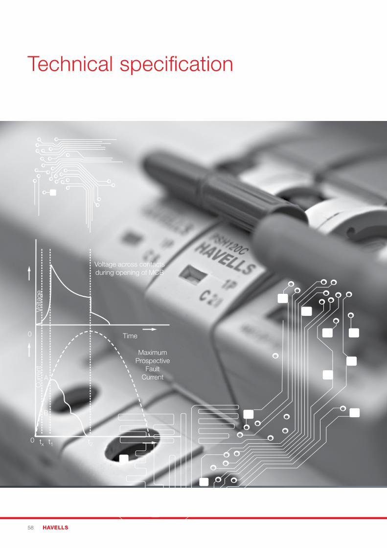
58 HAVELLS
Technical specification
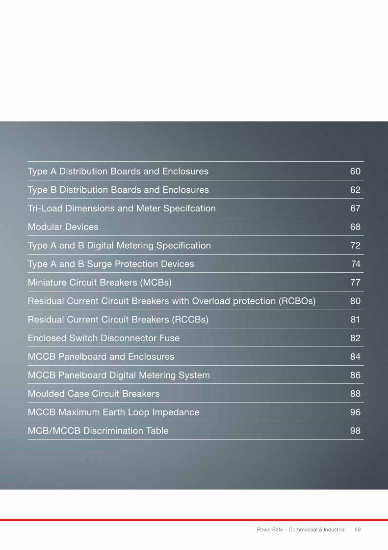
PowerSafe – Commercial & Industrial 59
Type A Distribution Boards and Enclosures 60
Type B Distribution Boards and Enclosures 62
Tri-Load Dimensions and Meter Specifcation 67
Modular Devices 68
Type A and B Digital Metering Specification 72
Type A and B Surge Protection Devices 74
Miniature Circuit Breakers (MCBs) 77
Residual Current Circuit Breakers with Overload protection (RCBOs) 80
Residual Current Circuit Breakers (RCCBs) 81
Enclosed Switch Disconnector Fuse 82
MCCB Panelboard and Enclosures 84
MCCB Panelboard Digital Metering System 86
Moulded Case Circuit Breakers 88
MCCB Maximum Earth Loop Impedance 96
MCB/MCCB Discrimination Table 98
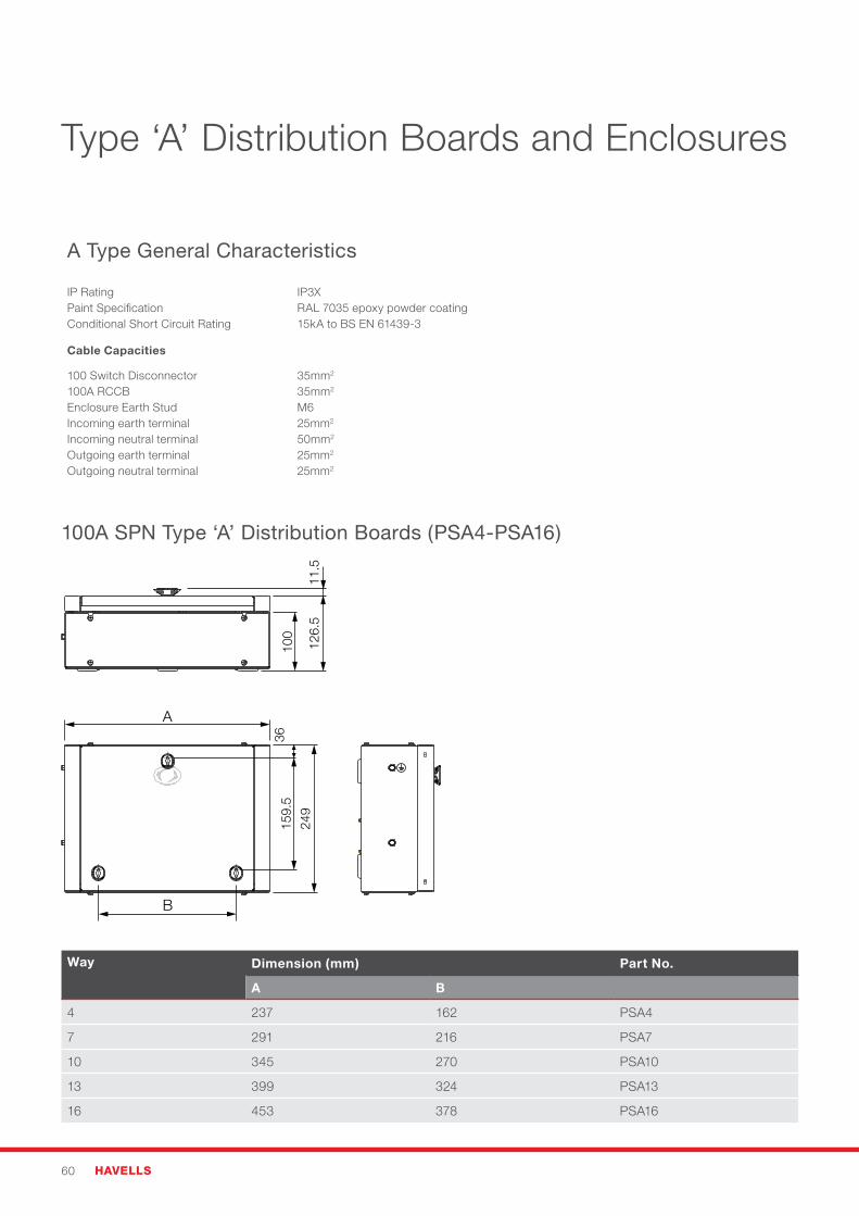
60 HAVELLS
100A SPN Type ‘A’ Distribution Boards (PSA4-PSA16)
Way Dimension (mm) Part No.
A B
4 237 162 PSA4
7 291 216 PSA7
10 345 270 PSA10
13 399 324 PSA13
16 453 378 PSA16
Type ‘A’ Distribution Boards and Enclosures
A Type General Characteristics
IP RatingPaint SpecificationConditional Short Circuit Rating
IP3XRAL 7035 epoxy powder coating15kA to BS EN 61439-3
Cable Capacities
100 Switch Disconnector100A RCCBEnclosure Earth StudIncoming earth terminalIncoming neutral terminalOutgoing earth terminalOutgoing neutral terminal
35mm2
35mm2
M625mm2
50mm2
25mm2
25mm2
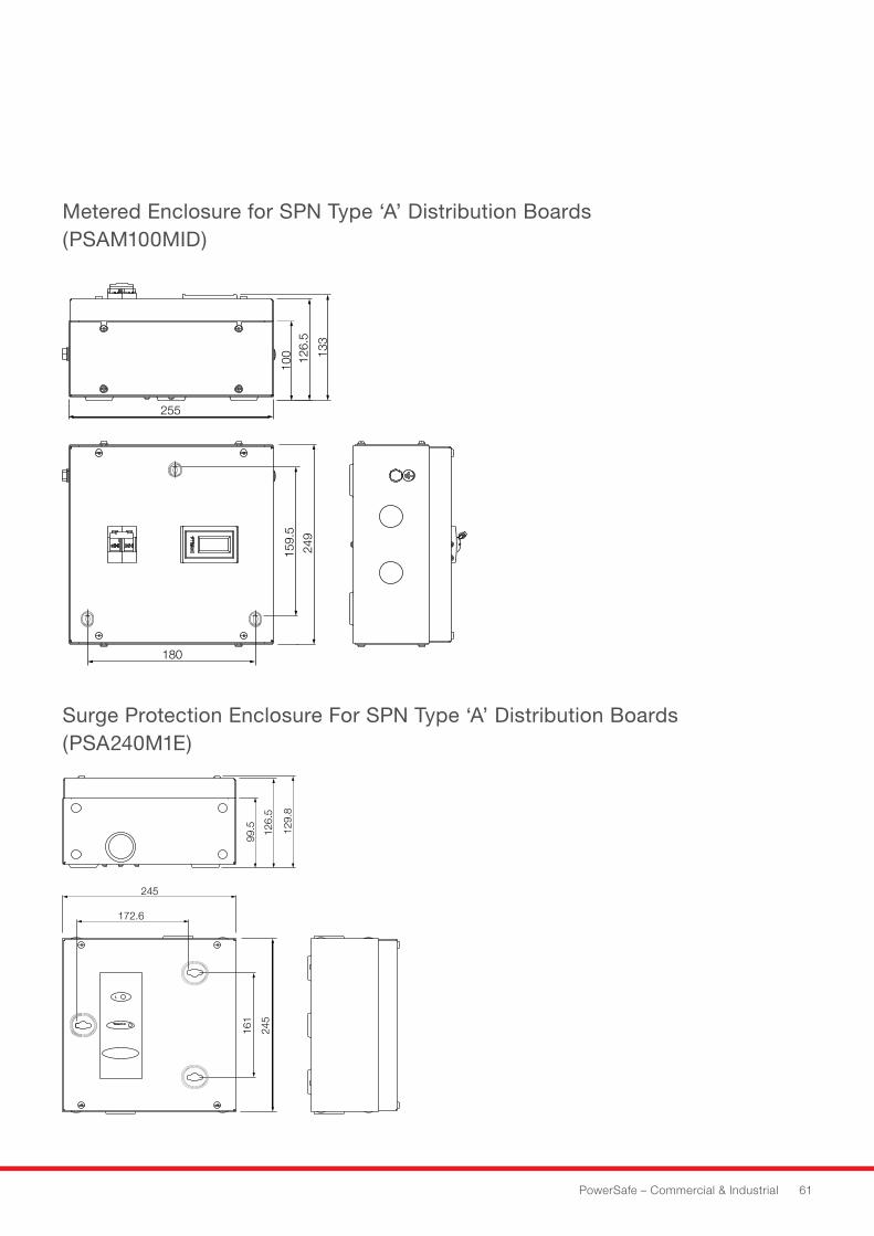
Surge Protection Enclosure For SPN Type ‘A’ Distribution Boards (PSA240M1E)
PowerSafe – Commercial & Industrial 61
Metered Enclosure for SPN Type ‘A’ Distribution Boards (PSAM100MID)
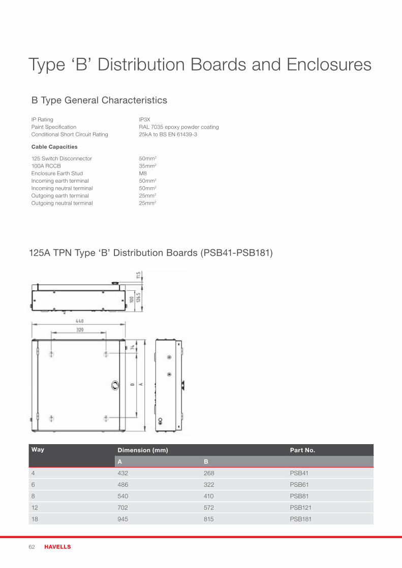
62 HAVELLS
Type ‘B’ Distribution Boards and Enclosures
B Type General Characteristics
IP RatingPaint SpecificationConditional Short Circuit Rating
IP3XRAL 7035 epoxy powder coating25kA to BS EN 61439-3
Cable Capacities
125 Switch Disconnector100A RCCBEnclosure Earth StudIncoming earth terminalIncoming neutral terminalOutgoing earth terminalOutgoing neutral terminal
50mm2
35mm2
M850mm2 50mm2
25mm2
25mm2
125A TPN Type ‘B’ Distribution Boards (PSB41-PSB181)
Way Dimension (mm) Part No.
A B
4 432 268 PSB41
6 486 322 PSB61
8 540 410 PSB81
12 702 572 PSB121
18 945 815 PSB181
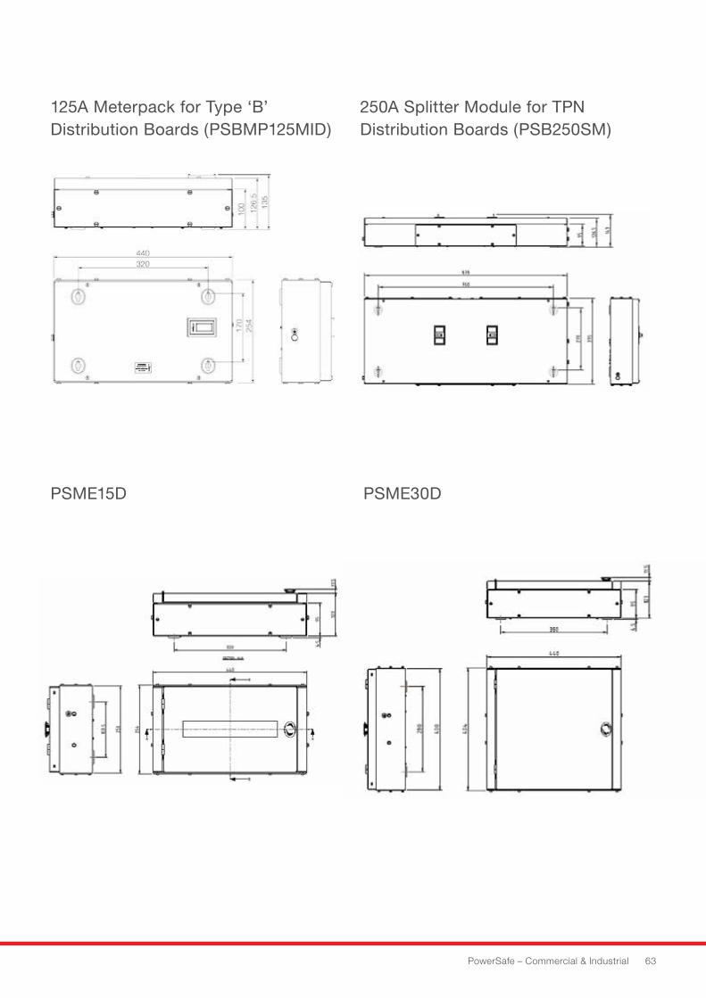
PowerSafe – Commercial & Industrial 63
125A Meterpack for Type ‘B’ Distribution Boards (PSBMP125MID)
PSME15D PSME30D
250A Splitter Module for TPN Distribution Boards (PSB250SM)
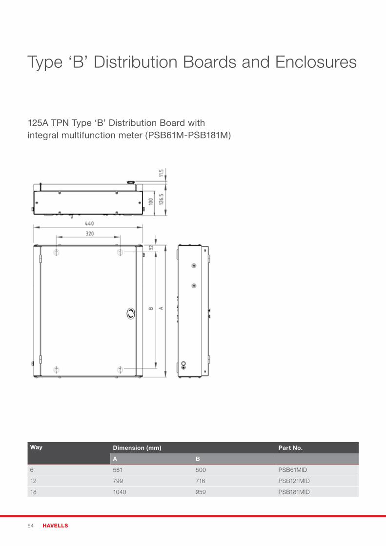
64 HAVELLS
Type ‘B’ Distribution Boards and Enclosures
125A TPN Type ‘B’ Distribution Board with integral multifunction meter (PSB61M-PSB181M)
Way Dimension (mm) Part No.
A B
6 581 500 PSB61MID
12 799 716 PSB121MID
18 1040 959 PSB181MID
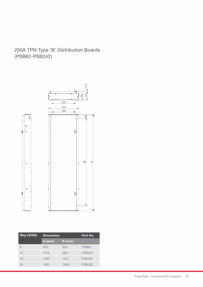
PowerSafe – Commercial & Industrial 65
Way (250A) Dimension Part No.
A (mm) B (mm)
6 956 820 PSB62
12 1118 982 PSB122
18 1263 1127 PSB182
24 1425 1289 PSB242
250A TPN Type ‘B’ Distribution Boards (PSB62-PSB242)
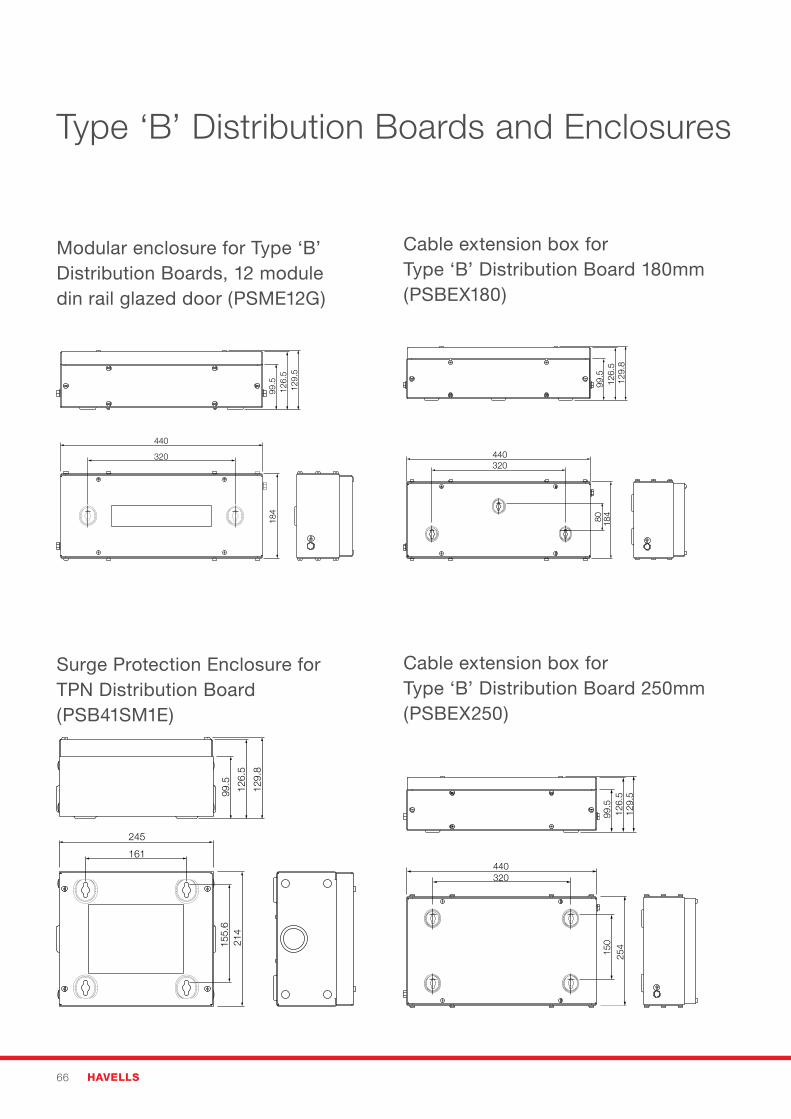
66 HAVELLS
Type ‘B’ Distribution Boards and Enclosures
Modular enclosure for Type ‘B’ Distribution Boards, 12 module din rail glazed door (PSME12G)
Surge Protection Enclosure for TPN Distribution Board (PSB41SM1E)
Cable extension box for Type ‘B’ Distribution Board 250mm (PSBEX250)
Cable extension box for Type ‘B’ Distribution Board 180mm (PSBEX180)
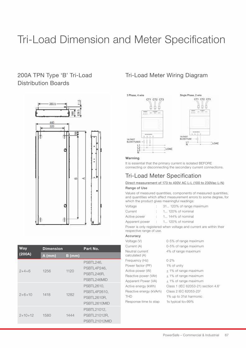
PowerSafe – Commercial & Industrial 67
Tri-Load Dimension and Meter Specification
Warning.
It is essential that the primary current is isolated BEFORE connecting or disconnecting the secondary current connections.
Tri-Load Meter SpecificationDirect measurement of 173 to 400V AC L-L (100 to 230Vac L-N)
Range of Use
Values of measured quantities, components of measured quantities, and quantities which affect measurement errors to some degree, for which the product gives meaningful readings:
Voltage : 31...120%ofrangemaximum
Current : 1...120%ofnominal
Activepower : 1...144%ofnominal
Apparentpower : 1...120%ofnominal
Power is only registered when voltage and current are within their respective range of use.
Accuracy
Voltage(V) 0-5%ofrangemaximum
Current(A) 0-5%ofrangemaximum
Neutralcurrent 4%ofrangemaximum calculated (A)
Frequency(Hz) 0-2%
Powerfactor(PF) 1%ofunity
Active power (W) +1%ofrangemaximum
Reactive power (VAr) +1%ofrangemaximum
Apparent Power (VA) +1%ofrangemaximum
Active energy (kWh) Class 1 (IEC 62053-21) section 4.61
Reactive energy (kVArh) Class 2 IEC 62053-232
THD 1%upto31stharmonic
Responsetimetostap 1stypicalto>99%
Way
(200A)Dimension Part No.
A (mm) B (mm)
2+4+6 1256 1120
PSBTL246,
PSBTL4P246,
PSBTL246R,
PSBTL246MID
2+6+10 1418 1282
PSBTL2610,
PSBTL4P2610,
PSBTL2610R,
PSBTL2610MID
2+10+12 1580 1444
PSBTL21012,
PSBTL21012R,
PSBTL21012MID
200A TPN Type ‘B’ Tri-Load Distribution Boards
Tri-Load Meter Wiring Diagram
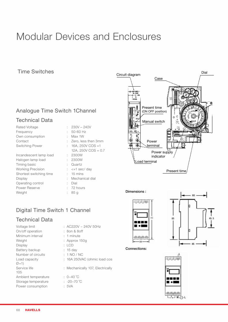
68 HAVELLS
Digital Time Switch 1 Channel
Technical DataVoltage limit : AC220V ~ 240V 50HzOn/off operation : 8on & 8offMinimum interval : 1 minuteWeight : Approx 150gDisplay : LCDBattery backup : 15 dayNumber of circuits : 1 NO / NCLoad capacity : 16A 250VAC (ohmic load cos Ø=1)Service life : Mechanically 107, Electrically 105Ambient temperature : 0~40 ˚CStorage temperature : -20~70 ˚CPower consumption : 5VA
Dimensions :
Connections:
Analogue Time Switch 1Channel
Technical DataRated Voltage : 230V – 240VFrequency : 50-60 HzOwn consumption : Max 1WContact : Zero, less then 3mmSwitching Power : 16A, 250V COS =1 12A, 250V COS = 0.7Incandescent lamp load : 2300WHalogen lamp load : 2300WTiming basic : QuartzWorking Precision : <+1 sec/ dayShortest switching time : 15 minsDisplay : Mechanical dialOperating control : DialPower Reserve : 72 hoursWeight : 85 g
Time SwitchesCircuit diagram
Case
Present time(ON OFF position)
Manual switch
Power terminal
Load terminal
Present time
Power supplyindicator
Dial
Modular Devices and Enclosures
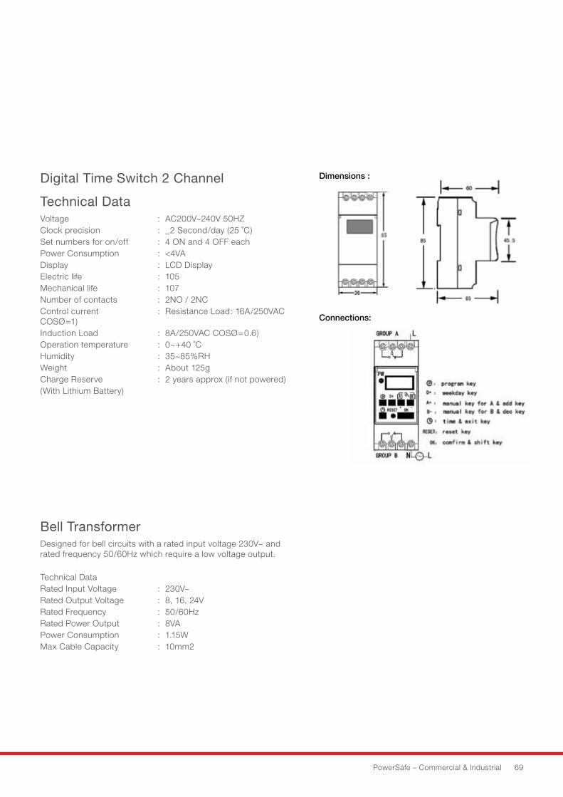
PowerSafe – Commercial & Industrial 69
Digital Time Switch 2 Channel
Technical DataVoltage : AC200V~240V 50HZClock precision : _2 Second/day (25 ˚C)Set numbers for on/off : 4 ON and 4 OFF eachPower Consumption : <4VADisplay : LCD DisplayElectric life : 105Mechanical life : 107Number of contacts : 2NO / 2NCControl current : Resistance Load: 16A/250VAC COSØ=1)Induction Load : 8A/250VAC COSØ=0.6)Operation temperature : 0~+40 ˚CHumidity :35~85%RHWeight : About 125gCharge Reserve : 2 years approx (if not powered)(With Lithium Battery)
Bell TransformerDesigned for bell circuits with a rated input voltage 230V~ and rated frequency 50/60Hz which require a low voltage output.
Technical DataRated Input Voltage : 230V~Rated Output Voltage : 8, 16, 24VRated Frequency : 50/60HzRated Power Output : 8VAPower Consumption : 1.15WMax Cable Capacity : 10mm2
Dimensions :
Connections:
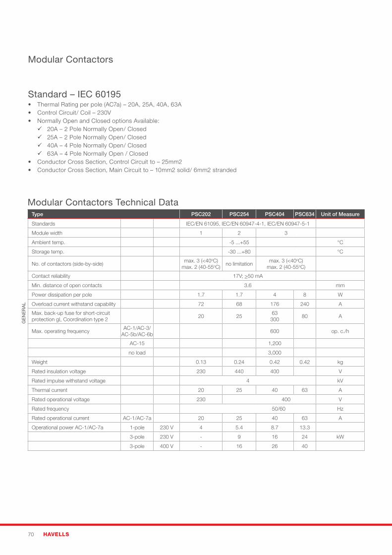
70 HAVELLS
Modular Contactors Technical Data Type PSC202 PSC254 PSC404 PSC634 Unit of Measure
Standards IEC/EN 61095, IEC/EN 60947-4-1, IEC/EN 60947-5-1
Module width 1 2 3
Ambient temp. -5 ...+55 °C
Storage temp. -30 ...+80 °C
No. of contactors (side-by-side)max. 3 (<40oC)
max. 2 (40-55oC)no limitation
max. 3 (<40oC)max. 2 (40-55oC)
Contact reliability 17V;>50 mA
Min. distance of open contacts 3.6 mm
Power dissipation per pole 1.7 1.7 4 8 W
Overload current withstand capability 72 68 176 240 A
Max. back-up fuse for short-circuitprotection gL Coordination type 2
20 2563300
80 A
Max. operating frequencyAC-1/AC-3/
AC-5b/AC-6b600 op. c./h
AC-15 1,200
no load 3,000
Weight 0.13 0.24 0.42 0.42 kg
Rated insulation voltage 230 440 400 V
Rated impulse withstand voltage 4 kV
Thermal current 20 25 40 63 A
Rated operational voltage 230 400 V
Rated frequency 50/60 Hz
Rated operational current AC-1/AC-7a 20 25 40 63 A
Operational power AC-1/AC-7a 1-pole 230 V 4 5.4 8.7 13.3
3-pole 230 V - 9 16 24 kW
3-pole 400 V - 16 26 40
GE
NE
RA
L
Standard – IEC 60195• ThermalRatingperpole(AC7a)–20A,25A,40A,63A• ControlCircuit/Coil–230V• NormallyOpenandClosedoptionsAvailable: 20A – 2 Pole Normally Open/ Closed 25A – 2 Pole Normally Open/ Closed 40A – 4 Pole Normally Open/ Closed 63A – 4 Pole Normally Open / Closed• ConductorCrossSection,ControlCircuitto–25mm2• ConductorCrossSection,MainCircuitto–10mm2solid/6mm2stranded
Modular Contactors
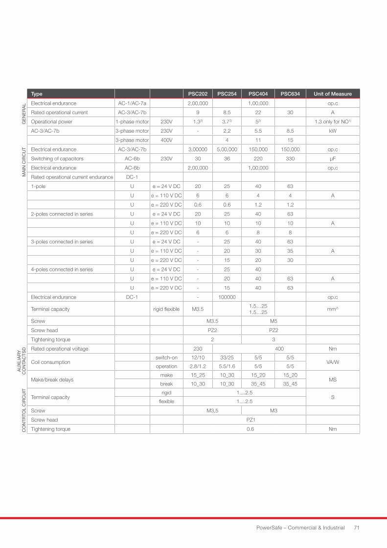
PowerSafe – Commercial & Industrial 71
GE
NE
RA
LM
AIN
CIR
CU
TA
UX
LIA
RY
CO
NTA
CTS
DC
ON
TRTO
L C
IRC
UIT
Type PSC202 PSC254 PSC404 PSC634 Unit of Measure
Electrical endurance AC-1/AC-7a 2,00,000 1,00,000 op.c
Rated operational current AC-3/AC-7b 9 8.5 22 30 A
Operational power 1-phase motor 230V 1.32) 3.72) 52) 1.3 only for NO1)
AC-3/AC-7b 3-phase motor 230V - 2,2 5.5 8.5 kW
3-phase motor 400V 4 11 15
Electrical endurance AC-3/AC-7b 3,00000 5,00,000 150,000 150,000 op.c
Switching of capacitors AC-6b 230V 30 36 220 330 μF
Electrical endurance AC-6b 2,00,000 1,00,000 op.c
Rated operational current endurance DC-1
1-pole U e = 24 V DC 20 25 40 63
U e = 110 V DC 6 6 4 4 A
U e = 220 V DC 0.6 0.6 1.2 1.2
2-poles connected in series U e = 24 V DC 20 25 40 63
U e = 110 V DC 10 10 10 10 A
U e = 220 V DC 6 6 8 8
3-poles connected in series U e = 24 V DC - 25 40 63
U e = 110 V DC - 20 30 35 A
U e = 220 V DC - 15 20 30
4-poles connected in series U e = 24 V DC - 25 40
U e = 110 V DC - 20 40 63 A
U e = 220 V DC - 15 40 63
Electrical endurance DC-1 - 100000 op.c
Terminal capacity rigid flexible M3.51.5…25 1.5…25
mm2)
Screw M3.5 M5
Screw head PZ2 PZ2
Tightening torque 2 3
Rated operational voltage 230 400 Nm
Coil consumptionswitch-on 12/10 33/25 5/5 5/5
VA/Woperation 2.8/1.2 5.5/1.6 5/5 5/5
Make/break delaysmake 15_25 10_30 15_20 15_20
MSbreak 10_30 10_30 35_45 35_45
Terminal capacityrigid 1....2.5
Sflexible 1....2.5
Screw M3,5 M3
Screw head PZ1
Tightening torque 0.6 Nm
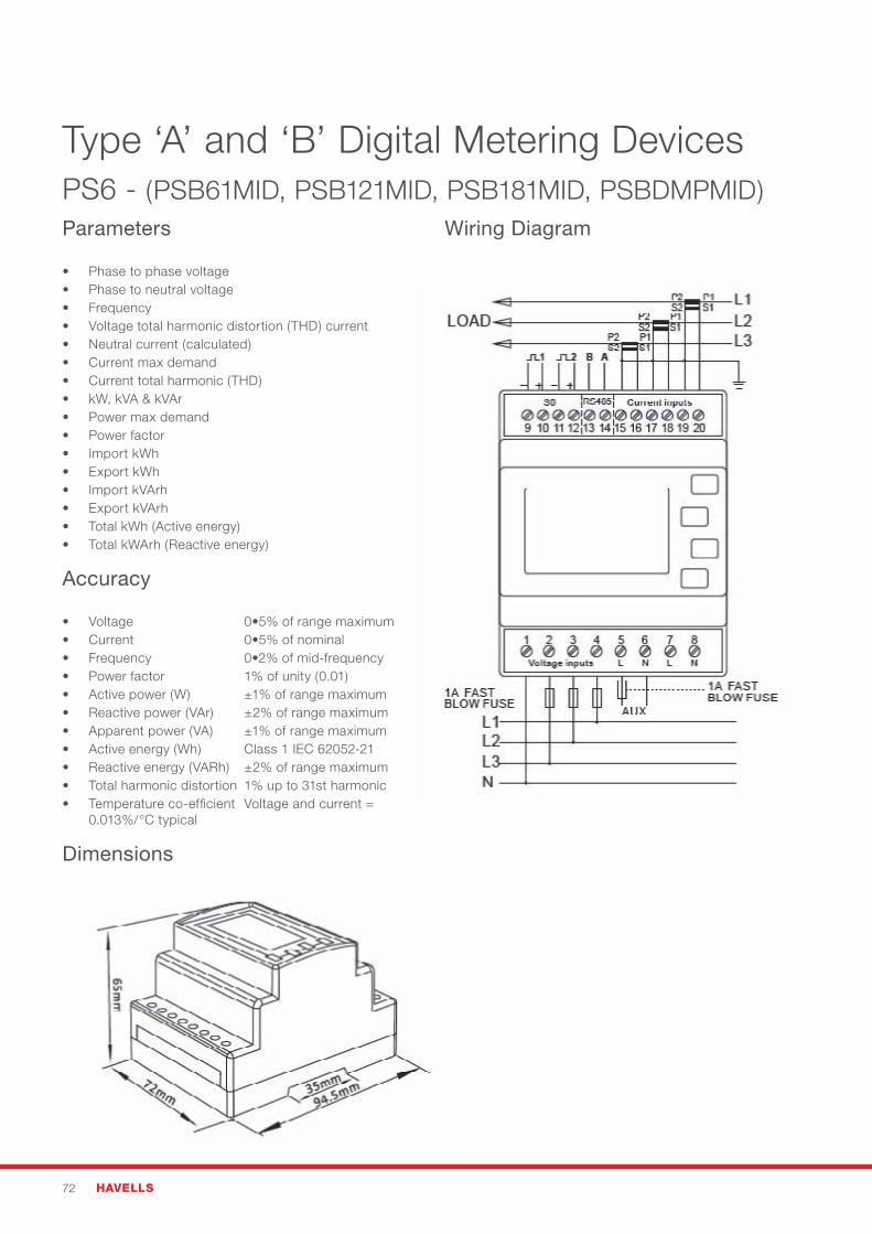
72 HAVELLS
Type ‘A’ and ‘B’ Digital Metering DevicesPS6 - (PSB61MID, PSB121MID, PSB181MID, PSBDMPMID)Parameters
• Phase to phase voltage• Phase to neutral voltage• Frequency• Voltage total harmonic distortion (THD) current• Neutral current (calculated)• Current max demand• Current total harmonic (THD)• kW, kVA & kVAr• Power max demand• Power factor• Import kWh• Export kWh• Import kVArh• Export kVArh• Total kWh (Active energy)• Total kWArh (Reactive energy)
Accuracy
• Voltage 0•5%ofrangemaximum• Current 0•5%ofnominal• Frequency 0•2%ofmid-frequency• Powerfactor 1%ofunity(0.01)• Activepower(W) ±1%ofrangemaximum• Reactivepower(VAr) ±2%ofrangemaximum• Apparentpower(VA) ±1%ofrangemaximum• Active energy (Wh) Class 1 IEC 62052-21• Reactiveenergy(VARh) ±2%ofrangemaximum• Totalharmonicdistortion 1%upto31stharmonic• Temperature co-efficient Voltage and current =
0.013%/°Ctypical
Wiring Diagram
Dimensions

PowerSafe – Commercial & Industrial 73
Type ‘A’ and ‘B’ Digital Metering DevicesPS7 / PS8 - (PSAM100MID, PSMD1100MID, PSMD3100MID)ParametersPS7 - Single Phase Direct Connect 100APS8 - Three Phase Direct Connect 100A
Voltage and Current• Phase to neutral voltage 176 to 276V a.c.• Percentagetotalvoltageharmonicdistortion(THD%)for
phase to N• Phase current• CurrentTHD%
Power factor and Frequency andMax. Demand• Frequency in Hz• Instantaneous Power Power 0 to999MW• Reactive Power 0 to 999MVAr• Volt-amps 0 to 999 MVA• Maximum demanded power since last Demand reset
Power factor
Energy Measurements• Imported active energy 0 to 99999.9 kWh• Exported active energy 0 to 99999.9 kWh• Imported reactive energy 0 to 99999.9 kVArh• Exported reactive energy 0 to 99999.9 kVArh• Total active energy 0 to 99999.9 kWh• Total reactive energy 0 to 99999.9 kVArh
MID Approved• Annex B & D
Accuracy• Voltage 0•5%ofrangemaximum• Current 0•5%ofnominal• Frequency 0•2%ofmid-frequency• Powerfactor 1%ofunity(0.01)• Activepower(W) ±1%ofrangemaximum• Reactivepower(VAr) ±2%ofrangemaximum• Apparentpower(VA) ±1%ofrangemaximum• Active energy (Wh) Class 1 IEC 62053-21• Reactiveenergy(VARh) ±2%ofrangemaximum• Totalharmonicdistortion 1%upto31stharmonic• Temperature co-efficient Voltage and current =
0.013%/°Ctypical• Activeenergy =0•018%/°C,typical• Responsetimetostepinput 1s,typical,to>99%of
final reading, at 50 Hz.
Environment•Operatingtemperature -25°Cto+55°C*•Storagetemperature -40°Cto+70°C*•Relativehumidity 0to90%,non-condensing•Altitude Upto2000m•Warmuptime 1minute•Vibration 10Hzto50Hz,IEC60068-2-6, 2g•Shock 30gin3planes
*Maximum operating and storage temperatures are in the context of typical daily and seasonal variation.
Wiring Diagram (PS7)
Wiring Diagram (PS8)
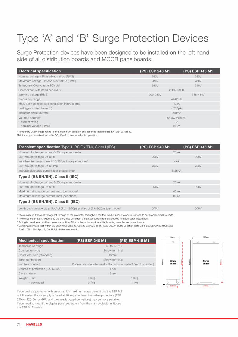
74 HAVELLS
Type ‘A’ and ‘B’ Surge Protection Devices
Electrical specification (PS) ESP 240 M1 (PS) ESP 415 M1Nominal voltage - Phase-Neutral Uo (RMS) 240V 240V
Maximum voltage - Phase-Neutral Uc (RMS) 280V 280V
Temporary Overvoltage TOV UT1 350V 350V
Short circuit withstand capability 25kA, 50Hz
Working voltage (RMS) 200-280V 346-484V
Frequency range 47-63Hz
Max. back-up fuse (see installation instructions) 125A
Leakage current (to earth) <250μA
Indicator circuit current <10mA
Volt free contact2
– current rating– nominal voltage (RMS)
Screw terminal1A
250V
Transient specification Type 1 (BS EN/EN), Class I (IEC) (PS) ESP 240 M1 (PS) ESP 415 M1Nominal discharge current 8/20μs (per mode) In 20kA
Let-through voltage Up at In1 900V 900V
Impulse discharge current 10/350μs Iimp (per mode)2 4kA
Let-through voltage Up at Iimp1 750V 750V
Impulse discharge current (per phase) limp3 6.25kA
Type 2 (BS EN/EN), Class II (IEC)Nominal discharge current 8/20μs (per mode) In 20kA
Let-through voltage Up at In1 900V 900V
Maximum discharge current Imax (per mode)2 40kA
Maximum discharge current Imax (per phase) 80kA
Type 3 (BS EN/EN), Class III (IEC)
Let-through voltage Up at Uoc1 of 6kV 1.2/50μs and Isc of 3kA 8/20μs (per mode)4 600V 600V
Mechanical specification (PS) ESP 240 M1 (PS) ESP 415 M1Temperature range –40 to +70ºC
Connection type Screw terminal
Conductor size (stranded) 16mm2
Earth connection Screw terminal
Volt free contact Connect via screw terminal with conductor up to 2.5mm2 (stranded)
Degree of protection (IEC 60529) IP20
Case material Steel
Weight – unit 0.6kg 1.0kg
– packaged 0.7kg 1.1kg
1 Temporary Overvoltage rating is for a maximum duration of 5 seconds tested to BS EN/EN/IEC 61643.2 Minimum permissable load is 5V DC, 10mA to ensure reliable operation.
1Themaximumtransientvoltagelet-throughoftheprotectorthroughoutthetest(±5%),phasetoneutral,phasetoearthandneutraltoearth.2 The electrical system, external to the unit, may constrain the actual current rating achieved in a particular installation.3 Rating is considered as the current capability of the protector for equipotential bonding near the service entrance.4 Combination wave test within BS 6651:1999 App. C, Cats C-Low & B-High, IEEE C62.41-2002 Location Cats C1 & B3, SS CP 33:1996 App.
F, AS 1768-1991 App. B, Cat B, UL1449 mains wire-in.
Depth=73mm
M5 clearance
NOTE:The unit takesup 20mm ofthe length ofthe fixingscrew.
Depth=73mm
M5 clearance
NOTE:The unit takesup 20mm ofthe length ofthe fixingscrew.
If you desire a protector with an extra high maximum surge current use the ESP M2 or M4 series. If your supply is fused at 16 amps, or less, the in-line protectors (ESP 240 (or 120-5A (or -16A) and their ready boxed derivatives) may be more suitable. If you need to mount the display panel separately from the main protector unit, use the ESP M1R series.
Surge Protection devices have been designed to be installed on the left hand side of all distribution boards and MCCB panelboards.
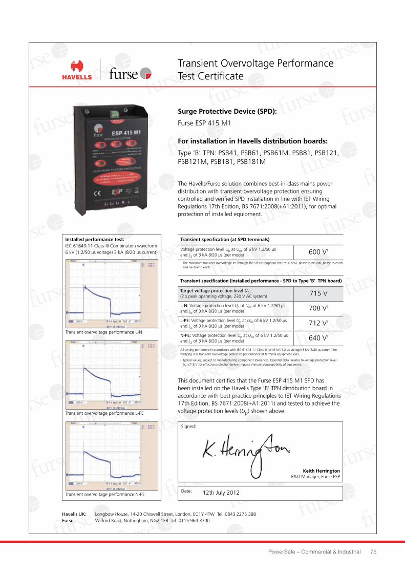
PowerSafe – Commercial & Industrial 75
N-PE: Voltage protection level Up at Uoc of 6 kV 1.2/50 µsand Isc of 3 kA 8/20 µs (per mode) 640 V2
L-PE: Voltage protection level Up at Uoc of 6 kV 1.2/50 µsand Isc of 3 kA 8/20 µs (per mode) 712 V2
Transient overvoltage performance L-N
Transient overvoltage performance L-PE
Transient overvoltage performance N-PE
Transient Overvoltage PerformanceTest Certificate
Surge Protective Device (SPD):
Furse ESP 415 M1
For installation in Havells distribution boards:
Type ‘B’ TPN: PSB41, PSB61, PSB61M, PSB81, PSB121,PSB121M, PSB181, PSB181M
The Havells/Furse solution combines best-in-class mains powerdistribution with transient overvoltage protection ensuringcontrolled and verified SPD installation in line with IET WiringRegulations 17th Edition, BS 7671:2008(+A1:2011), for optimalprotection of installed equipment.
Installed performance test:IEC 61643-11 Class III Combination waveform6 kV (1.2/50 µs voltage) 3 kA (8/20 µs current)
Date:
Transient specification (at SPD terminals)
Voltage protection level Up at Uoc of 6 kV 1.2/50 µsand Isc of 3 kA 8/20 µs (per mode) 600 V1
All testing performed in accordance with IEC 61643-11 Class III test 6 kV (1.2 µs voltage) 3 kA (8/20 µs current) forverifying SPD transient overvoltage protective performance at terminal equipment level.
2 Typical values, subject to manufacturing component tolerances. Essential detail relates to voltage protection levelUp <715 V for effective protection below impulse immunity/susceptibility of equipment.
Transient specification (installed performance - SPD to Type ‘B’ TPN board)
L-N: Voltage protection level Up at Uoc of 6 kV 1.2/50 µsand Isc of 3 kA 8/20 µs (per mode) 708 V2
Target voltage protection level Up:(2 x peak operating voltage, 230 V AC system) 715 V
This document certifies that the Furse ESP 415 M1 SPD hasbeen installed on the Havells Type ‘B’ TPN distribution board inaccordance with best practice principles to IET Wiring Regulations17th Edition, BS 7671:2008(+A1:2011) and tested to achieve thevoltage protection levels (Up) shown above.
1 The maximum transient overvoltage let-through the SPD throughout the test (±5%), phase to neutral, phase to earthand neutral to earth.
Havells UK: Longbow House, 14-20 Chiswell Street, London, EC1Y 4TW Tel: 0843 2275 388Furse: Wilford Road, Nottingham, NG2 1EB Tel: 0115 964 3700
Signed:
Keith HerringtonR&D Manager, Furse ESP
12th July 2012
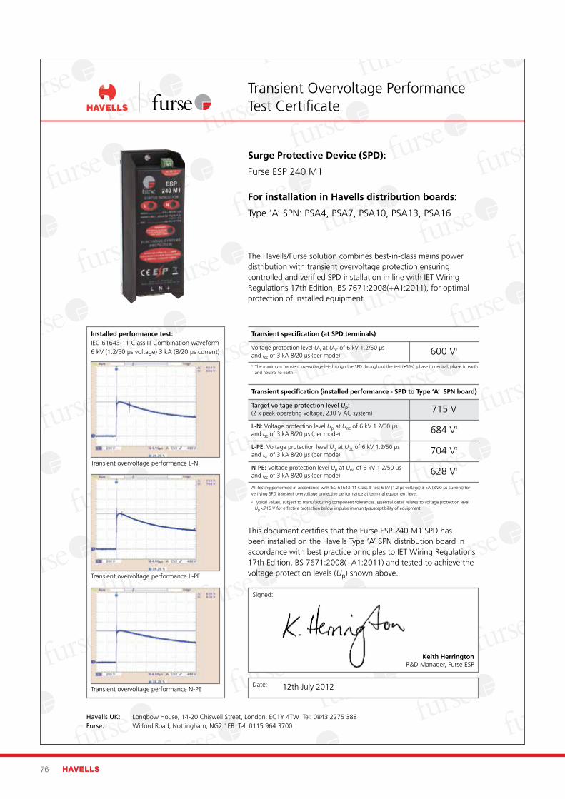
76 HAVELLS
N-PE: Voltage protection level Up at Uoc of 6 kV 1.2/50 µsand Isc of 3 kA 8/20 µs (per mode) 628 V2
L-PE: Voltage protection level Up at Uoc of 6 kV 1.2/50 µsand Isc of 3 kA 8/20 µs (per mode) 704 V2
Transient overvoltage performance L-N
Transient overvoltage performance L-PE
Transient overvoltage performance N-PE
Transient Overvoltage PerformanceTest Certificate
Surge Protective Device (SPD):
Furse ESP 240 M1
For installation in Havells distribution boards:
Type ‘A’ SPN: PSA4, PSA7, PSA10, PSA13, PSA16
The Havells/Furse solution combines best-in-class mains powerdistribution with transient overvoltage protection ensuringcontrolled and verified SPD installation in line with IET WiringRegulations 17th Edition, BS 7671:2008(+A1:2011), for optimalprotection of installed equipment.
Installed performance test:IEC 61643-11 Class III Combination waveform6 kV (1.2/50 µs voltage) 3 kA (8/20 µs current)
Date:
Transient specification (at SPD terminals)
Voltage protection level Up at Uoc of 6 kV 1.2/50 µsand Isc of 3 kA 8/20 µs (per mode) 600 V1
All testing performed in accordance with IEC 61643-11 Class III test 6 kV (1.2 µs voltage) 3 kA (8/20 µs current) forverifying SPD transient overvoltage protective performance at terminal equipment level.
2 Typical values, subject to manufacturing component tolerances. Essential detail relates to voltage protection levelUp <715 V for effective protection below impulse immunity/susceptibility of equipment.
Transient specification (installed performance - SPD to Type ‘A’ SPN board)
L-N: Voltage protection level Up at Uoc of 6 kV 1.2/50 µsand Isc of 3 kA 8/20 µs (per mode) 684 V2
Target voltage protection level Up:(2 x peak operating voltage, 230 V AC system) 715 V
This document certifies that the Furse ESP 240 M1 SPD hasbeen installed on the Havells Type ‘A’ SPN distribution board inaccordance with best practice principles to IET Wiring Regulations17th Edition, BS 7671:2008(+A1:2011) and tested to achieve thevoltage protection levels (Up) shown above.
1 The maximum transient overvoltage let-through the SPD throughout the test (±5%), phase to neutral, phase to earthand neutral to earth.
Havells UK: Longbow House, 14-20 Chiswell Street, London, EC1Y 4TW Tel: 0843 2275 388Furse: Wilford Road, Nottingham, NG2 1EB Tel: 0115 964 3700
Signed:
Keith HerringtonR&D Manager, Furse ESP
12th July 2012
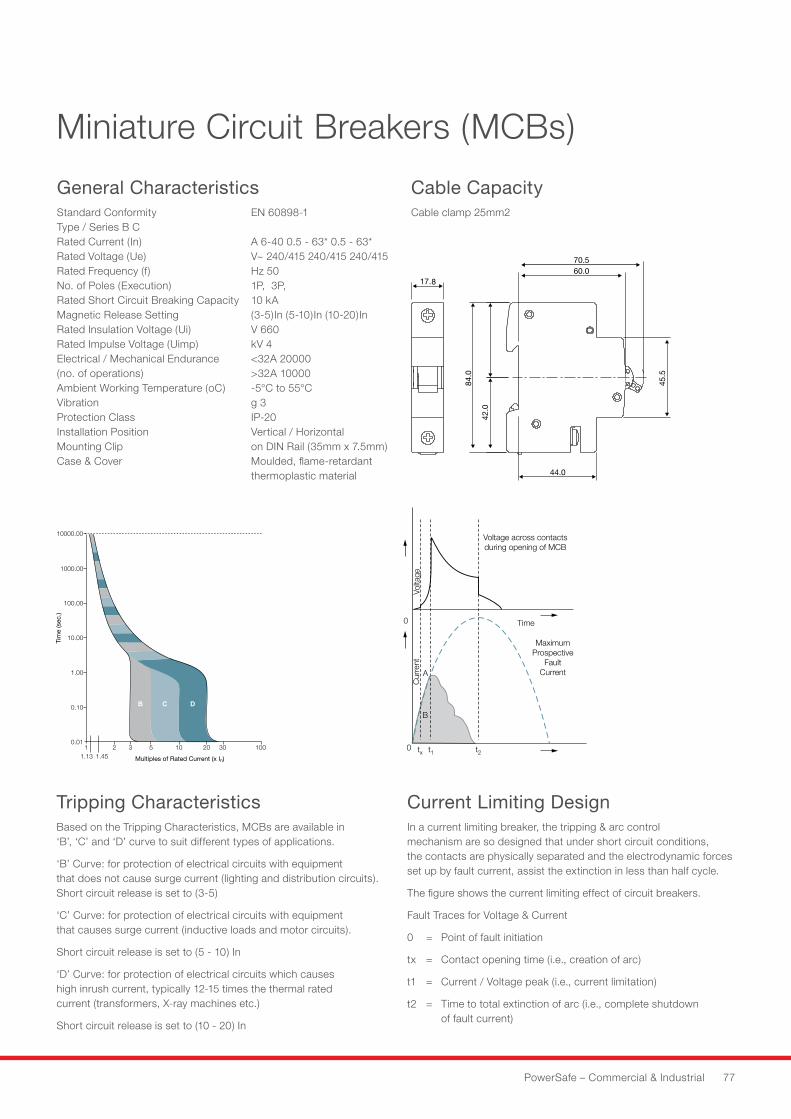
Multiples of Rated Current (x In)
Tim
e (s
ec.)
10000.00
1000.00
100.00
10.00
1.00
0.10
0.011 2 3 5 10 20 30 100
1.13 1.45
Voltage across contactsduring opening of MCB
MaximumProspective
FaultCurrent
Time
Cur
rent
Volta
ge
A
B
0
0 tx t1 t2
PowerSafe – Commercial & Industrial 77
Miniature Circuit Breakers (MCBs)
General CharacteristicsStandard Conformity EN 60898-1Type / Series B CRated Current (In) A 6-40 0.5 - 63* 0.5 - 63*Rated Voltage (Ue) V~ 240/415 240/415 240/415Rated Frequency (f) Hz 50No. of Poles (Execution) 1P, 3P,Rated Short Circuit Breaking Capacity 10 kAMagnetic Release Setting (3-5)In (5-10)In (10-20)InRated Insulation Voltage (Ui) V 660Rated Impulse Voltage (Uimp) kV 4Electrical / Mechanical Endurance <32A 20000 (no. of operations) >32A 10000Ambient Working Temperature (oC) -5°C to 55°CVibration g 3Protection Class IP-20Installation Position Vertical / HorizontalMounting Clip on DIN Rail (35mm x 7.5mm)Case & Cover Moulded, flame-retardant thermoplastic material
Tripping CharacteristicsBased on the Tripping Characteristics, MCBs are available in ‘B’, ‘C’ and ‘D’ curve to suit different types of applications.
‘B’ Curve: for protection of electrical circuits with equipment that does not cause surge current (lighting and distribution circuits). Short circuit release is set to (3-5)
‘C’ Curve: for protection of electrical circuits with equipment that causes surge current (inductive loads and motor circuits).
Short circuit release is set to (5 - 10) In
‘D’ Curve: for protection of electrical circuits which causes high inrush current, typically 12-15 times the thermal rated current (transformers, X-ray machines etc.)
Short circuit release is set to (10 - 20) In
Current Limiting DesignIn a current limiting breaker, the tripping & arc control mechanism are so designed that under short circuit conditions, the contacts are physically separated and the electrodynamic forces set up by fault current, assist the extinction in less than half cycle.
The figure shows the current limiting effect of circuit breakers.
Fault Traces for Voltage & Current
0 = Point of fault initiation
tx = Contact opening time (i.e., creation of arc)
t1 = Current / Voltage peak (i.e., current limitation)
t2 = Time to total extinction of arc (i.e., complete shutdown of fault current)
Cable Capacity Cable clamp 25mm2
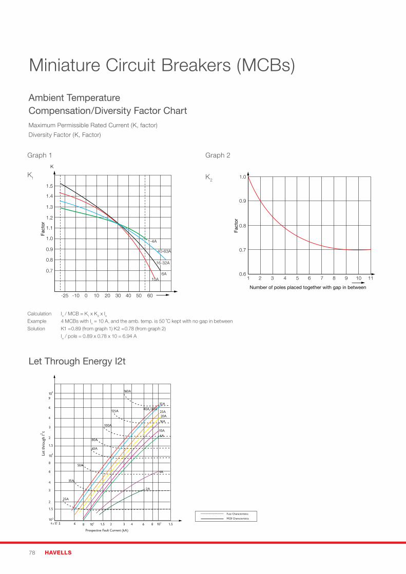
78 HAVELLS
Miniature Circuit Breakers (MCBs)
Ambient Temperature Compensation/Diversity Factor ChartMaximum Permissible Rated Current (K, factor)
Diversity Factor (K, Factor)
Let Through Energy I2t
K1
Graph 1
-25 -10 0 10 20 30 40 50 60
10A6A
0.7
0.8
0.9
1.0
1.1
1.2
1.3
1.4
1.5
16-32A
40-63A
1-4A
K
Fact
or
Number of poles placed together with gap in between
1 2 3 4 5 6 7 8 9 10 110.6
0.7
0.8
0.9
1.0
Fact
or
K2
Graph 2
Calculation In / MCB = K1 x K2 x InExample 4 MCBs with In = 10 A, and the amb. temp. is 50 ˚C kept with no gap in between
Solution K1 =0.89 (from graph 1) K2 =0.78 (from graph 2)
In / pole = 0.89 x 0.78 x 10 = 6.94 A
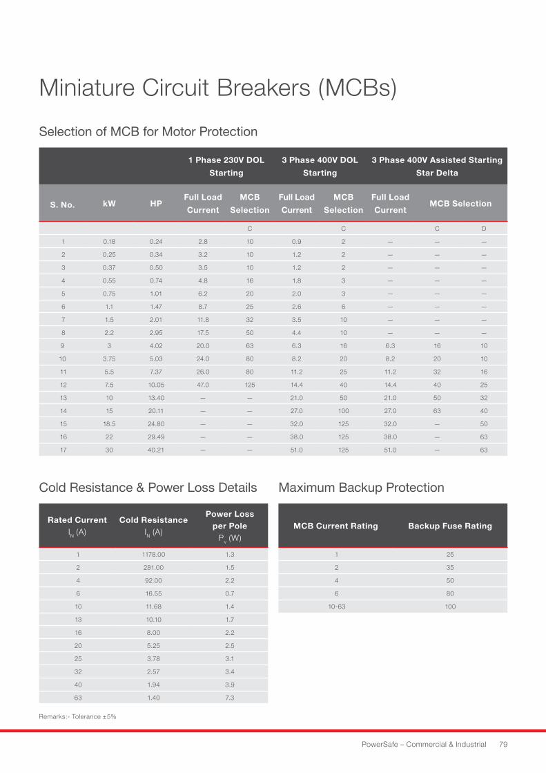
PowerSafe – Commercial & Industrial 79
Miniature Circuit Breakers (MCBs)
Selection of MCB for Motor Protection
Cold Resistance & Power Loss Details Maximum Backup Protection
1 Phase 230V DOL
Starting
3 Phase 400V DOL
Starting
3 Phase 400V Assisted Starting
Star Delta
S. No. kW HPFull Load
Current
MCB
Selection
Full Load
Current
MCB
Selection
Full Load
CurrentMCB Selection
C C C D
1 0.18 0.24 2.8 10 0.9 2 — — —
2 0.25 0.34 3.2 10 1.2 2 — — —
3 0.37 0.50 3.5 10 1.2 2 — — —
4 0.55 0.74 4.8 16 1.8 3 — — —
5 0.75 1.01 6.2 20 2.0 3 — — —
6 1.1 1.47 8.7 25 2.6 6 — — —
7 1.5 2.01 11.8 32 3.5 10 — — —
8 2.2 2.95 17.5 50 4.4 10 — — —
9 3 4.02 20.0 63 6.3 16 6.3 16 10
10 3.75 5.03 24.0 80 8.2 20 8.2 20 10
11 5.5 7.37 26.0 80 11.2 25 11.2 32 16
12 7.5 10.05 47.0 125 14.4 40 14.4 40 25
13 10 13.40 — — 21.0 50 21.0 50 32
14 15 20.11 — — 27.0 100 27.0 63 40
15 18.5 24.80 — — 32.0 125 32.0 — 50
16 22 29.49 — — 38.0 125 38.0 — 63
17 30 40.21 — — 51.0 125 51.0 — 63
Rated CurrentIN (A)
Cold ResistanceIN (A)
Power Loss per Pole
Pv (W)
1 1178.00 1.3
2 281.00 1.5
4 92.00 2.2
6 16.55 0.7
10 11.68 1.4
13 10.10 1.7
16 8.00 2.2
20 5.25 2.5
25 3.78 3.1
32 2.57 3.4
40 1.94 3.9
63 1.40 7.3
Remarks:-Tolerance±5%
MCB Current Rating Backup Fuse Rating
1 25
2 35
4 50
6 80
10-63 100
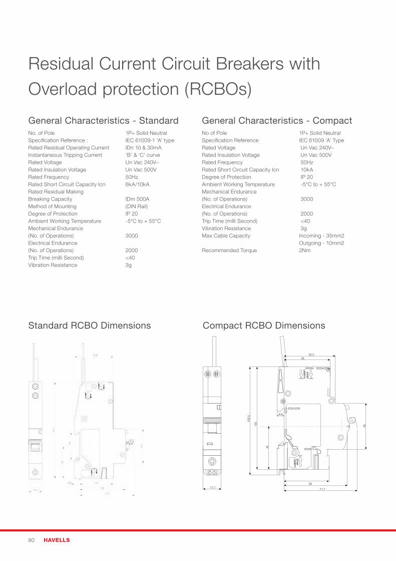
80 HAVELLS
Residual Current Circuit Breakers with Overload protection (RCBOs)
General Characteristics - StandardNo. of Pole 1P+ Solid NeutralSpecification Reference : IEC 61009-1 ‘A’ typeRated Residual Operating Current IDn 10 & 30mAInstantaneous Tripping Current ‘B’ & ‘C’ curveRated Voltage Un Vac 240V~Rated Insulation Voltage Un Vac 500VRated Frequency 50HzRated Short Circuit Capacity Icn 6kA/10kARated Residual Making Breaking Capacity IDm 500AMethod of Mounting (DIN Rail)Degree of Protection IP 20Ambient Working Temperature -5°C to + 55°CMechanical Endurance (No. of Operations) 3000Electrical Endurance (No. of Operations) 2000Trip Time (milli Second) <40Vibration Resistance 3g
General Characteristics - CompactNo of Pole 1P+ Solid NeutralSpecification Reference IEC 61009 ‘A’ TypeRated Voltage Un Vac 240V~ Rated Insulation Voltage Un Vac 500V Rated Frequency 50Hz Rated Short Circuit Capacity Icn 10kA Degree of Protection IP 20 Ambient Working Temperature -5°C to + 55°C Mechanical Endurance (No. of Operations) 3000Electrical Endurance(No. of Operations) 2000Trip Time (milli Second) <40 Vibration Resistance 3g Max Cable Capacity Incoming - 35mm2 Outgoing - 10mm2Recommended Torque 2Nm
Standard RCBO Dimensions Compact RCBO Dimensions
45
6.8
105.
5
100
62
45
42
50.2
71.717.7
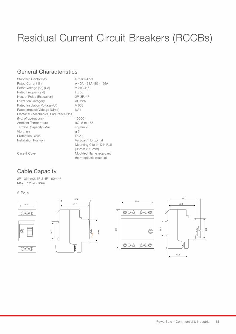
PowerSafe – Commercial & Industrial 81
Residual Current Circuit Breakers (RCCBs)
General CharacteristicsStandard Conformity IEC 60947-3Rated Current (In) A 40A - 63A, 80 - 125ARated Voltage (ac) (Ue) V 240/415Rated Frequency (f) Hz 50Nos. of Poles (Execution) 2P, 3P, 4PUtilization Category AC 22ARated Insulation Voltage (Ui) V 660Rated Impulse Voltage (Uimp) kV 4Electrical / Mechanical Endurance Nos (No. of operations) 10000Ambient Temperature 0C -5 to +55Terminal Capacity (Max) sq.mm 25Vibration g 5Protection Class IP-20Installation Position Vertical / Horizontal Mounting Clip on DIN Rail (35mm x 7.5mm)Case & Cover Moulded, flame retardant thermoplastic material
Cable Capacity 2P - 35mm2, 3P & 4P - 50mm2 Max. Torque - 3Nm
4ÊPOLE 2ÊPOLE 4ÊPOLE 2ÊPOLE2 Pole
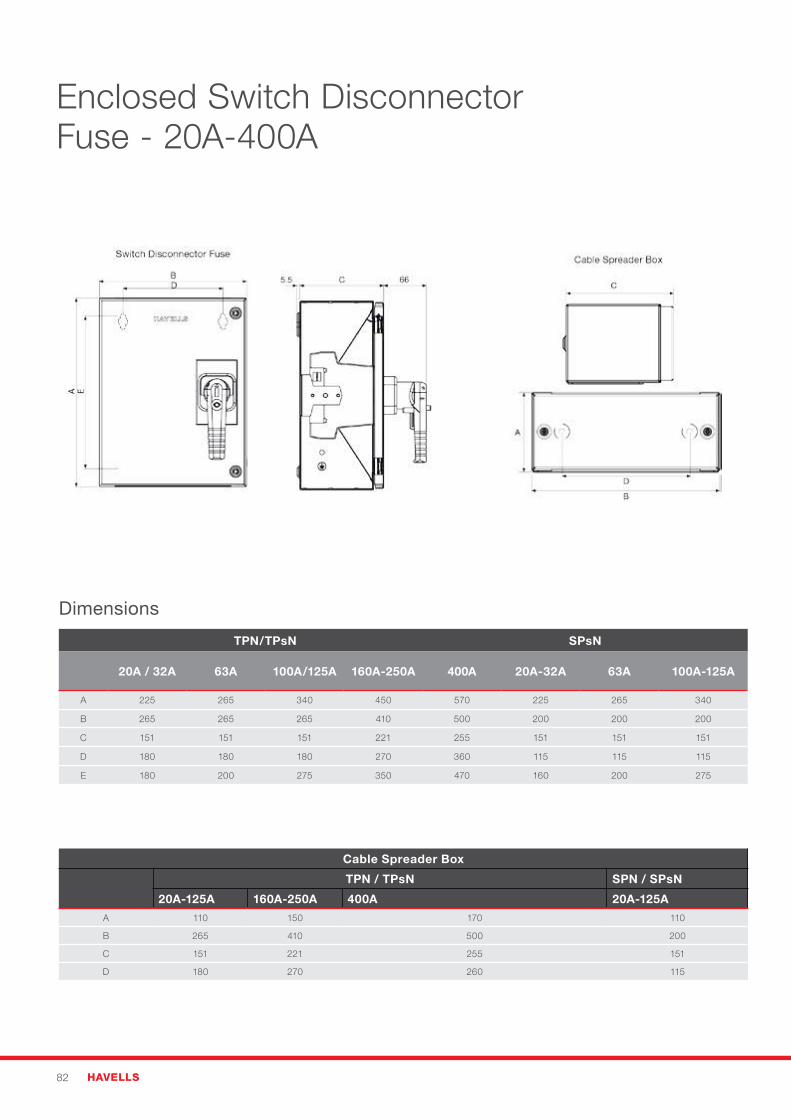
82 HAVELLS
Enclosed Switch Disconnector Fuse - 20A-400A
TPN/TPsN SPsN
20A / 32A 63A 100A/125A 160A-250A 400A 20A-32A 63A 100A-125A
A 225 265 340 450 570 225 265 340
B 265 265 265 410 500 200 200 200
C 151 151 151 221 255 151 151 151
D 180 180 180 270 360 115 115 115
E 180 200 275 350 470 160 200 275
Cable Spreader Box
TPN / TPsN SPN / SPsN
20A-125A 160A-250A 400A 20A-125A
A 110 150 170 110
B 265 410 500 200
C 151 221 255 151
D 180 270 260 115
Dimensions
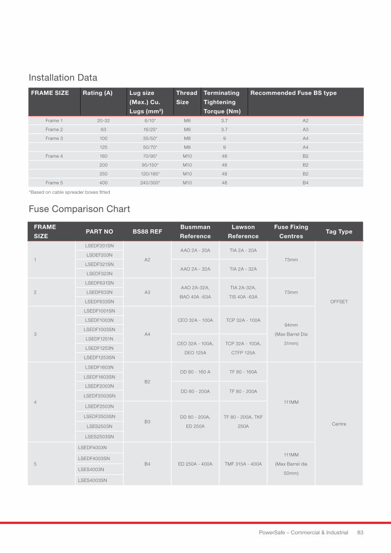
PowerSafe – Commercial & Industrial 83
FRAME
SIZEPART NO BS88 REF
Busmman
Reference
Lawson
Reference
Fuse Fixing
CentresTag Type
1
LSEDF201SN
A2
AAO 2A - 20A TIA 2A - 20A
73mm
OFFSET
LSDEF203N
LSEDF321SNAAO 2A - 32A TIA 2A - 32A
LSEDF323N
2
LSEDF631SN
A3AAO 2A-32A,
BAO 40A -63A
TIA 2A-32A,
TIS 40A -63A73mmLSEDF633N
LSEDF633SN
3
LSEDF1001SN
A4
CEO 32A - 100A TCP 32A - 100A94mm
(Max Barrel Dia
31mm)
LSEDF1003N
LSEDF1003SN
LSEDF1251NCEO 32A - 100A,
DEO 125A
TCP 32A - 100A,
CTFP 125ALSEDF1253N
LSEDF1253SN
4
LSEDF1603N
B2
DD 80 - 160 A TF 80 - 160A
111MM
Centre
LSEDF1603SN
LSEDF2003NDD 80 - 200A TF 80 - 200A
LSEDF2003SN
LSEDF2503N
B3DD 80 - 200A,
ED 250A
TF 80 - 200A, TKF
250A
LSEDF2503SN
LSES2503N
LSES2503SN
5
LSEDF4003N
B4 ED 250A - 400A TMF 315A - 400A
111MM
(Max Barrel dia
50mm)
LSEDF4003SN
LSES4003N
LSES4003SN
FRAME SIZE Rating (A) Lug size
(Max.) Cu.
Lugs (mm2)
Thread
Size
Terminating
Tightening
Torque (Nm)
Recommended Fuse BS type
Frame 1 20-32 6/10* M6 3.7 A2
Frame 2 63 16/25* M6 3.7 A3
Frame 3 100 35/50* M8 9 A4
125 50/70* M8 9 A4
Frame 4 160 70/95* M10 48 B2
200 95/150* M10 48 B2
250 120/185* M10 48 B2
Frame 5 400 240/300* M10 48 B4
Cable Spreader Box
TPN / TPsN SPN / SPsN
20A-125A 160A-250A 400A 20A-125A
A 110 150 170 110
B 265 410 500 200
C 151 221 255 151
D 180 270 260 115
*Based on cable spreader boxes fitted
Fuse Comparison Chart
Installation Data
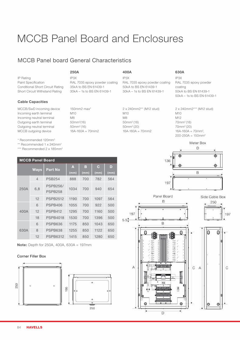
84 HAVELLS
MCCB Panel Board and Enclosures
MCCB Panel board General Characteristics
250A 400A 630A
IP RatingPaint SpecificationConditional Short Circuit RatingShort Circuit Withstand Rating
IP3XRAL 7035 epoxy powder coating35kA to BS EN 61439-130kA – 1s to BS EN 61439-1
IP3XRAL 7035 epoxy powder coating50kA to BS EN 61439-130kA – 1s to BS EN 61439-1
IP3XRAL 7035 epoxy powder coating50kA to BS EN 61439-150kA – 1s to BS EN 61439-1
Cable Capacities
MCCB/SwD incoming deviceIncoming earth terminalIncoming neutral terminalOutgoing earth terminalOutgoing neutral terminalMCCB outgoing device
* Recommended 120mm2
** Recommended 1 x 240mm2 *** Recommended 2 x 185mm2
150mm2 max*M10M850mm2(16)50mm2 (16)16A-160A = 70mm2
2 x 240mm2** (M12 stud)M10M850mm2 (18)50mm2 (20)16A-160A = 70mm2
2 x 240mm2*** (M12 stud)M10M1270mm2 (18)70mm2 (20)16A-160A = 70mm2, 200-250A = 150mm2
MCCB Panel Board
Ways Part NoA
(mm)
B
(mm)
C
(mm)
D
(mm)
250A
4 PSB254 888 700 782 564
6,8PSPB256/
PSPB2581034 700 940 654
12 PSPB2512 1190 700 1097 564
400A
6 PSPB406 1055 700 922 500
12 PSPB412 1295 700 1160 500
18 PSPB4018 1530 700 1396 500
630A
6 PSPB636 1175 850 1043 650
8 PSPB638 1255 850 1122 650
12 PSPB6312 1415 850 1280 650
Note: Depth for 250A, 400A, 630A = 197mm
Corner Filler Box

PowerSafe – Commercial & Industrial 85
N-PE: Voltage protection level Up at Uoc of 6 kV 1.2/50 µsand Isc of 3 kA 8/20 µs (per mode) 656 V2
L-PE: Voltage protection level Up at Uoc of 6 kV 1.2/50 µsand Isc of 3 kA 8/20 µs (per mode) 684 V2
Transient overvoltage performance L-N
Transient overvoltage performance L-PE
Transient overvoltage performance N-PE
Transient Overvoltage PerformanceTest Certificate
Surge Protective Device (SPD):
Furse ESP 415 M1
For installation in Havells distribution boards:
MCCB: PSPB254, PSPB256, PSPB258, PSPB406,PSPB408, PSPB4012, PSPB636, PSPB6312
The Havells/Furse solution combines best-in-class mains powerdistribution with transient overvoltage protection ensuringcontrolled and verified SPD installation in line with IET WiringRegulations 17th Edition, BS 7671:2008(+A1:2011), for optimalprotection of installed equipment.
Installed performance test:IEC 61643-11 Class III Combination waveform6 kV (1.2/50 µs voltage) 3 kA (8/20 µs current)
Date:
Transient specification (at SPD terminals)
Voltage protection level Up at Uoc of 6 kV 1.2/50 µsand Isc of 3 kA 8/20 µs (per mode) 600 V1
All testing performed in accordance with IEC 61643-11 Class III test 6 kV (1.2 µs voltage) 3 kA (8/20 µs current) forverifying SPD transient overvoltage protective performance at terminal equipment level.
2 Typical values, subject to manufacturing component tolerances. Essential detail relates to voltage protection levelUp <715 V for effective protection below impulse immunity/susceptibility of equipment.
Transient specification (installed performance - SPD to MCCB board)
L-N: Voltage protection level Up at Uoc of 6 kV 1.2/50 µsand Isc of 3 kA 8/20 µs (per mode) 712 V2
Target voltage protection level Up:(2 x peak operating voltage, 230 V AC system) 715 V
This document certifies that the Furse ESP 415 M1 SPD has beeninstalled on the Havells MCCB distribution board in accordancewith best practice principles to IET Wiring Regulations 17thEdition, BS 7671:2008(+A1:2011) and tested to achieve thevoltage protection levels (Up) shown above.
1 The maximum transient overvoltage let-through the SPD throughout the test (±5%), phase to neutral, phase to earthand neutral to earth.
Havells UK: Longbow House, 14-20 Chiswell Street, London, EC1Y 4TW Tel: 0843 2275 388Furse: Wilford Road, Nottingham, NG2 1EB Tel: 0115 964 3700
Signed:
Keith HerringtonR&D Manager, Furse ESP
12th July 2012
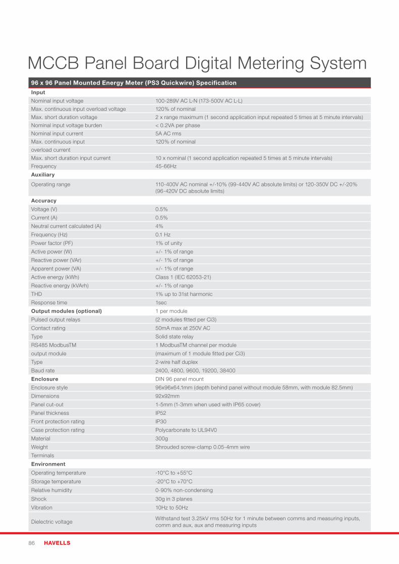
86 HAVELLS
96 x 96 Panel Mounted Energy Meter (PS3 Quickwire) Specification
Input
Nominal input voltage 100-289V AC L-N (173-500V AC L-L)
Max. continuous input overload voltage 120%ofnominal
Max. short duration voltage 2 x range maximum (1 second application input repeated 5 times at 5 minute intervals)
Nominal input voltage burden < 0.2VA per phase
Nominal input current 5A AC rms
Max. continuous input 120%ofnominal
overload current
Max. short duration input current 10 x nominal (1 second application repeated 5 times at 5 minute intervals)
Frequency 45-66Hz
Auxiliary
Operating range 110-400VACnominal+/-10%(99-440VACabsolutelimits)or120-350VDC+/-20%(96-420V DC absolute limits)
Accuracy
Voltage (V) 0.5%
Current (A) 0.5%
Neutral current calculated (A) 4%
Frequency (Hz) 0.1 Hz
Power factor (PF) 1%ofunity
Active power (W) +/-1%ofrange
Reactive power (VAr) +/-1%ofrange
Apparent power (VA) +/-1%ofrange
Active energy (kWh) Class 1 (IEC 62053-21)
Reactive energy (kVArh) +/-1%ofrange
THD 1%upto31stharmonic
Response time 1sec
Output modules (optional) 1 per module
Pulsed output relays (2 modules fitted per Ci3)
Contact rating 50mA max at 250V AC
Type Solid state relay
RS485 ModbusTM 1 ModbusTM channel per module
output module (maximum of 1 module fitted per Ci3)
Type 2-wire half duplex
Baud rate 2400, 4800, 9600, 19200, 38400
Enclosure DIN 96 panel mount
Enclosure style 96x96x64.1mm (depth behind panel without module 58mm, with module 82.5mm)
Dimensions 92x92mm
Panel cut-out 1-5mm (1-3mm when used with IP65 cover)
Panel thickness IP52
Front protection rating IP30
Case protection rating Polycarbonate to UL94V0
Material 300g
Weight Shrouded screw-clamp 0.05-4mm wire
Terminals
Environment
Operating temperature -10°C to +55°C
Storage temperature -20°C to +70°C
Relative humidity 0-90%non-condensing
Shock 30g in 3 planes
Vibration 10Hz to 50Hz
Dielectric voltageWithstand test 3.25kV rms 50Hz for 1 minute between comms and measuring inputs, comm and aux, aux and measuring inputs
MCCB Panel Board Digital Metering System
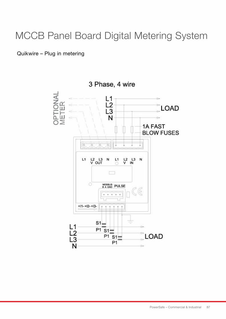
PowerSafe – Commercial & Industrial 87
MCCB Panel Board Digital Metering System
Quikwire – Plug in metering
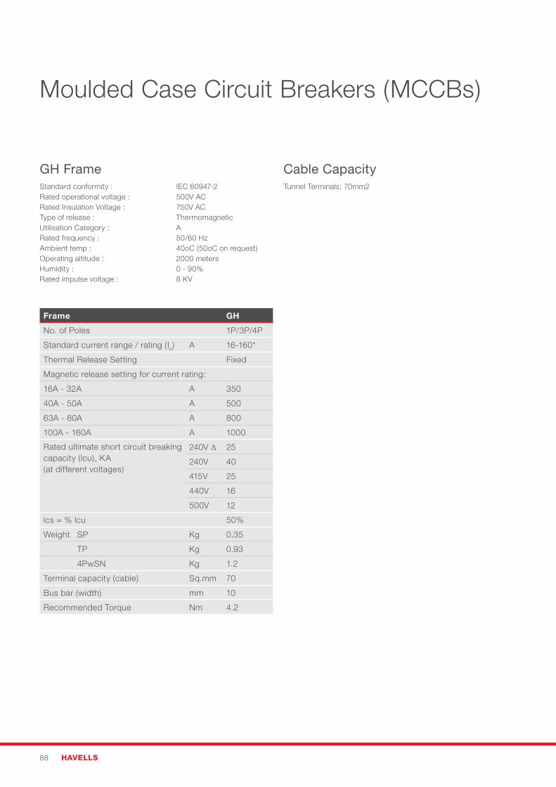
88 HAVELLS
Moulded Case Circuit Breakers (MCCBs)
Frame GH
No. of Poles 1P/3P/4P
Standard current range / rating (In) A 16-160*
Thermal Release Setting Fixed
Magnetic release setting for current rating:
16A - 32A A 350
40A - 50A A 500
63A - 80A A 800
100A - 160A A 1000
Rated ultimate short circuit breaking capacity (lcu), KA (at different voltages)
240V ∆ 25
240V 40
415V 25
440V 16
500V 12
lcs=%lcu 50%
Weight SP Kg 0.35
TP Kg 0.93
4PwSN Kg 1.2
Terminal capacity (cable) Sq.mm 70
Bus bar (width) mm 10
Recommended Torque Nm 4.2
GH Frame Standard conformity : IEC 60947-2Rated operational voltage : 500V ACRated Insulation Voltage : 750V ACType of release : ThermomagneticUtilisation Category : ARated frequency : 50/60 HzAmbient temp : 40oC (50oC on request)Operating altitude : 2000 metersHumidity: 0-90%Rated impulse voltage : 8 KV
Cable Capacity Tunnel Terminals: 70mm2
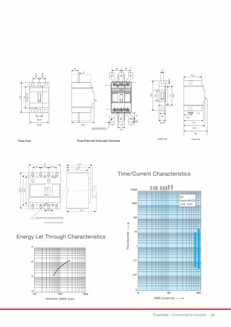
PowerSafe – Commercial & Industrial 89
Three Pole Three Pole with Extended Terminals
Time/Current Characteristics
Energy Let Through Characteristics
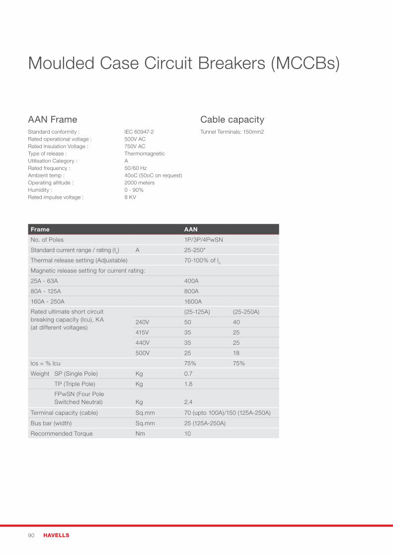
90 HAVELLS
Frame AAN
No. of Poles 1P/3P/4PwSN
Standard current range / rating (In) A 25-250*
Thermal release setting (Adjustable) 70-100%oflnMagnetic release setting for current rating:
25A - 63A 400A
80A - 125A 800A
160A - 250A 1600A
Rated ultimate short circuit breaking capacity (lcu), KA (at different voltages)
(25-125A) (25-250A)
240V 50 40
415V 35 25
440V 35 25
500V 25 18
lcs=%lcu 75% 75%
Weight SP (Single Pole) Kg 0.7
TP (Triple Pole) Kg 1.8
FPwSN (Four Pole Switched Neutral)
Kg
2.4
Terminal capacity (cable) Sq.mm 70 (upto 100A)/150 (125A-250A)
Bus bar (width) Sq.mm 25 (125A-250A)
Recommended Torque Nm 10
AAN FrameStandard conformity : IEC 60947-2Rated operational voltage : 500V ACRated Insulation Voltage : 750V ACType of release : ThermomagneticUtilisation Category : ARated frequency : 50/60 HzAmbient temp : 40oC (50oC on request)Operating altitude : 2000 metersHumidity: 0-90%Rated impulse voltage : 8 KV
Cable capacity Tunnel Terminals: 150mm2
Moulded Case Circuit Breakers (MCCBs)
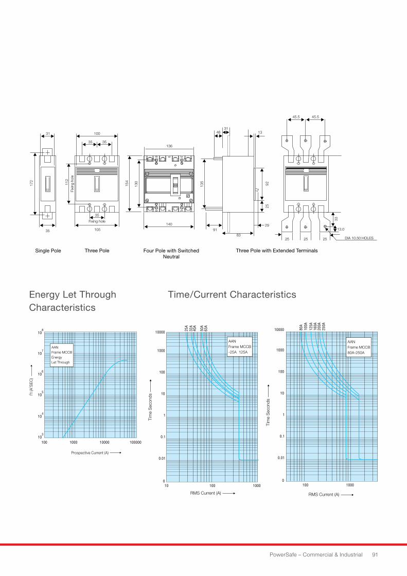
PowerSafe – Commercial & Industrial 91
Energy Let Through Characteristics
Time/Current Characteristics
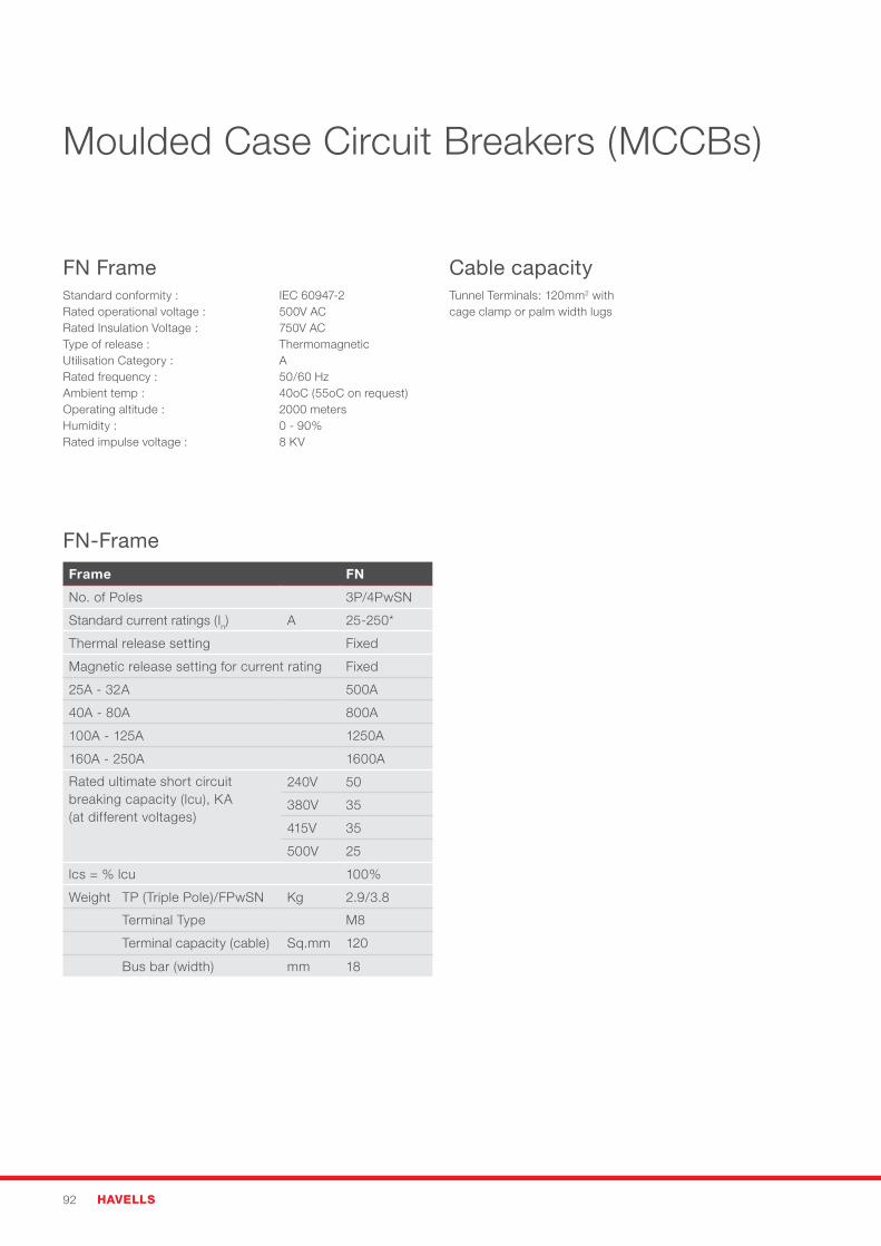
92 HAVELLS
Moulded Case Circuit Breakers (MCCBs)
FN FrameStandard conformity : IEC 60947-2Rated operational voltage : 500V ACRated Insulation Voltage : 750V ACType of release : ThermomagneticUtilisation Category : ARated frequency : 50/60 HzAmbient temp : 40oC (55oC on request)Operating altitude : 2000 metersHumidity: 0-90%Rated impulse voltage : 8 KV
Cable capacityTunnel Terminals: 120mm2 with cage clamp or palm width lugs
FN-Frame
Frame FN
No. of Poles 3P/4PwSN
Standard current ratings (In) A 25-250*
Thermal release setting Fixed
Magnetic release setting for current rating Fixed
25A - 32A 500A
40A - 80A 800A
100A - 125A 1250A
160A - 250A 1600A
Rated ultimate short circuit breaking capacity (lcu), KA (at different voltages)
240V 50
380V 35
415V 35
500V 25
lcs=%lcu 100%
Weight TP (Triple Pole)/FPwSN Kg 2.9/3.8
Terminal Type M8
Terminal capacity (cable) Sq.mm 120
Bus bar (width) mm 18
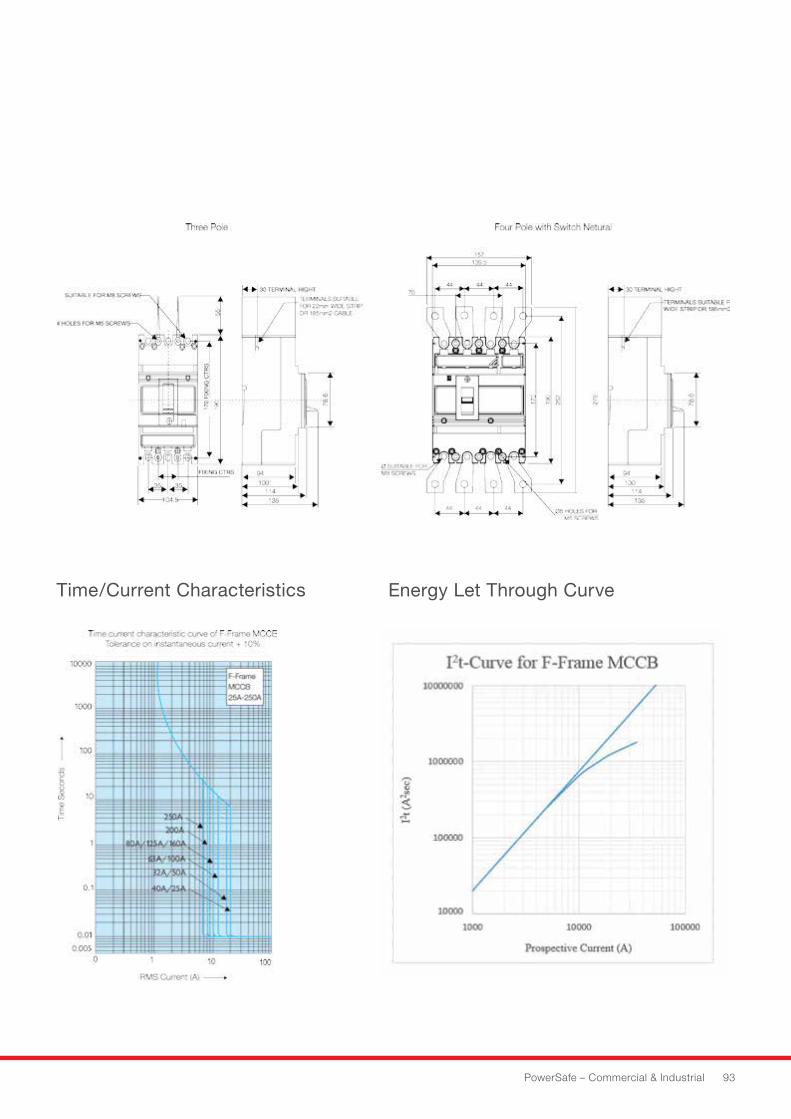
PowerSafe – Commercial & Industrial 93
Time/Current Characteristics Energy Let Through Curve
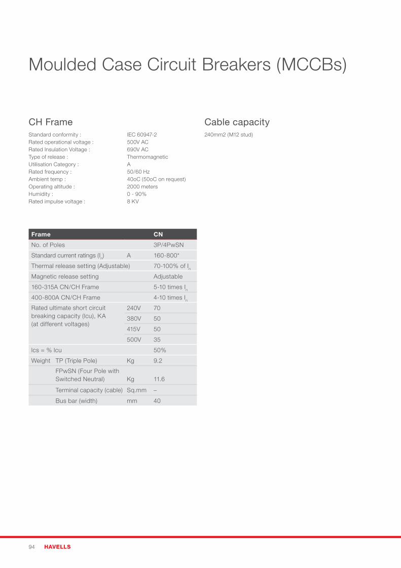
94 HAVELLS
Moulded Case Circuit Breakers (MCCBs)
CH FrameStandard conformity : IEC 60947-2Rated operational voltage : 500V ACRated Insulation Voltage : 690V ACType of release : ThermomagneticUtilisation Category : ARated frequency : 50/60 HzAmbient temp : 40oC (50oC on request)Operating altitude : 2000 metersHumidity: 0-90%Rated impulse voltage : 8 KV
Cable capacity240mm2 (M12 stud)
Frame CN
No. of Poles 3P/4PwSN
Standard current ratings (In) A 160-800*
Thermal release setting (Adjustable) 70-100%ofInMagnetic release setting Adjustable
160-315A CN/CH Frame 5-10 times In400-800A CN/CH Frame 4-10 times InRated ultimate short circuit breaking capacity (lcu), KA (at different voltages)
240V 70
380V 50
415V 50
500V 35
lcs=%lcu 50%
Weight TP (Triple Pole) Kg 9.2
FPwSN (Four Pole with Switched Neutral)
Kg
11.6
Terminal capacity (cable) Sq.mm –
Bus bar (width) mm 40
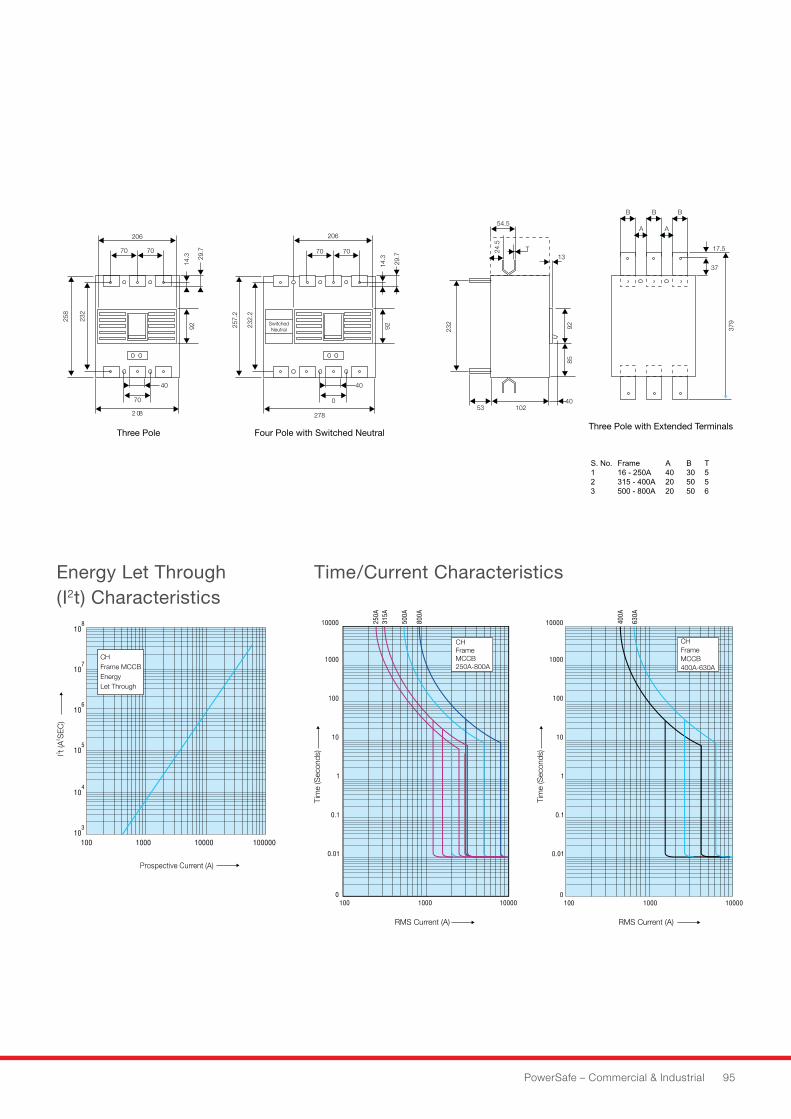
PowerSafe – Commercial & Industrial 95
Energy Let Through (I2t) Characteristics
Time/Current Characteristics
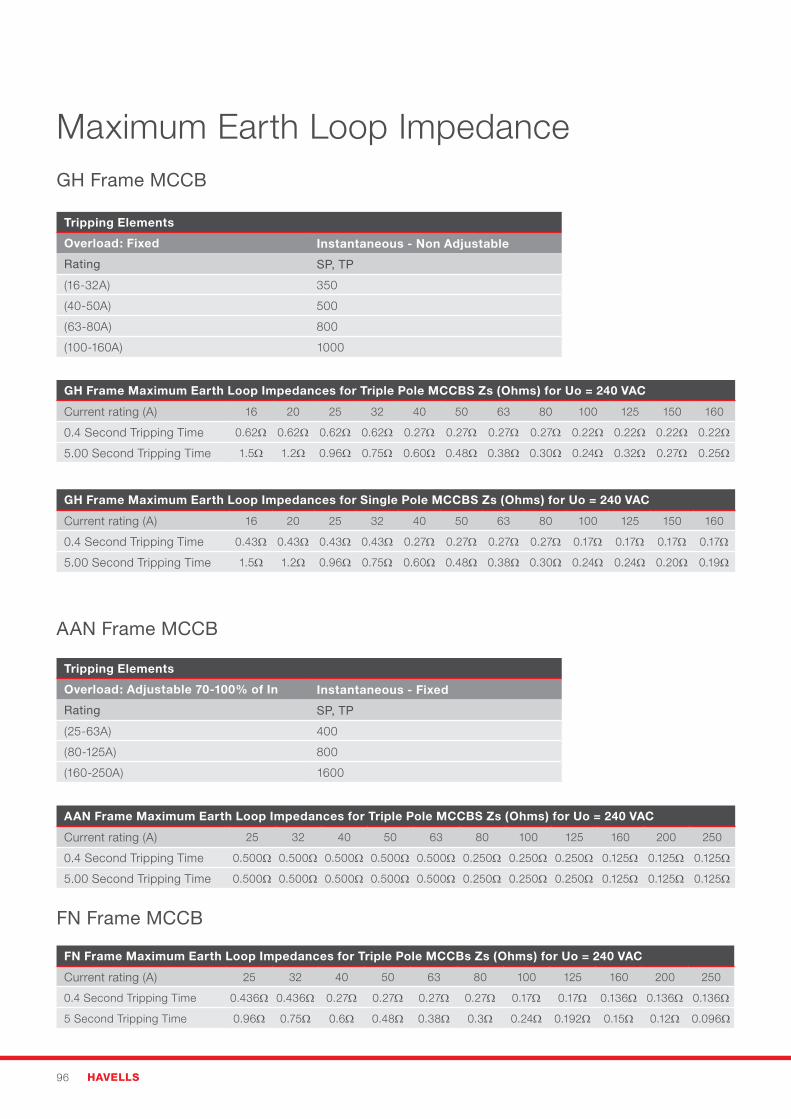
96 HAVELLS
Maximum Earth Loop ImpedanceGH Frame MCCB
Tripping Elements
Overload: Fixed Instantaneous - Non Adjustable
Rating SP, TP
(16-32A) 350
(40-50A) 500
(63-80A) 800
(100-160A) 1000
GH Frame Maximum Earth Loop Impedances for Triple Pole MCCBS Zs (Ohms) for Uo = 240 VAC
Current rating (A) 16 20 25 32 40 50 63 80 100 125 150 160
0.4 Second Tripping Time 0.62Ω 0.62Ω 0.62Ω 0.62Ω 0.27Ω 0.27Ω 0.27Ω 0.27Ω 0.22Ω 0.22Ω 0.22Ω 0.22Ω
5.00 Second Tripping Time 1.5Ω 1.2Ω 0.96Ω 0.75Ω 0.60Ω 0.48Ω 0.38Ω 0.30Ω 0.24Ω 0.32Ω 0.27Ω 0.25Ω
GH Frame Maximum Earth Loop Impedances for Single Pole MCCBS Zs (Ohms) for Uo = 240 VAC
Current rating (A) 16 20 25 32 40 50 63 80 100 125 150 160
0.4 Second Tripping Time 0.43Ω 0.43Ω 0.43Ω 0.43Ω 0.27Ω 0.27Ω 0.27Ω 0.27Ω 0.17Ω 0.17Ω 0.17Ω 0.17Ω
5.00 Second Tripping Time 1.5Ω 1.2Ω 0.96Ω 0.75Ω 0.60Ω 0.48Ω 0.38Ω 0.30Ω 0.24Ω 0.24Ω 0.20Ω 0.19Ω
AAN Frame MCCB
FN Frame MCCB
AAN Frame Maximum Earth Loop Impedances for Triple Pole MCCBS Zs (Ohms) for Uo = 240 VAC
Current rating (A) 25 32 40 50 63 80 100 125 160 200 250
0.4 Second Tripping Time 0.500Ω 0.500Ω 0.500Ω 0.500Ω 0.500Ω 0.250Ω 0.250Ω 0.250Ω 0.125Ω 0.125Ω 0.125Ω
5.00 Second Tripping Time 0.500Ω 0.500Ω 0.500Ω 0.500Ω 0.500Ω 0.250Ω 0.250Ω 0.250Ω 0.125Ω 0.125Ω 0.125Ω
FN Frame Maximum Earth Loop Impedances for Triple Pole MCCBs Zs (Ohms) for Uo = 240 VAC
Current rating (A) 25 32 40 50 63 80 100 125 160 200 250
0.4 Second Tripping Time 0.436Ω 0.436Ω 0.27Ω 0.27Ω 0.27Ω 0.27Ω 0.17Ω 0.17Ω 0.136Ω 0.136Ω 0.136Ω
5 Second Tripping Time 0.96Ω 0.75Ω 0.6Ω 0.48Ω 0.38Ω 0.3Ω 0.24Ω 0.192Ω 0.15Ω 0.12Ω 0.096Ω
Tripping Elements
Overload: Adjustable 70-100% of In Instantaneous - Fixed
Rating SP, TP
(25-63A) 400
(80-125A) 800
(160-250A) 1600
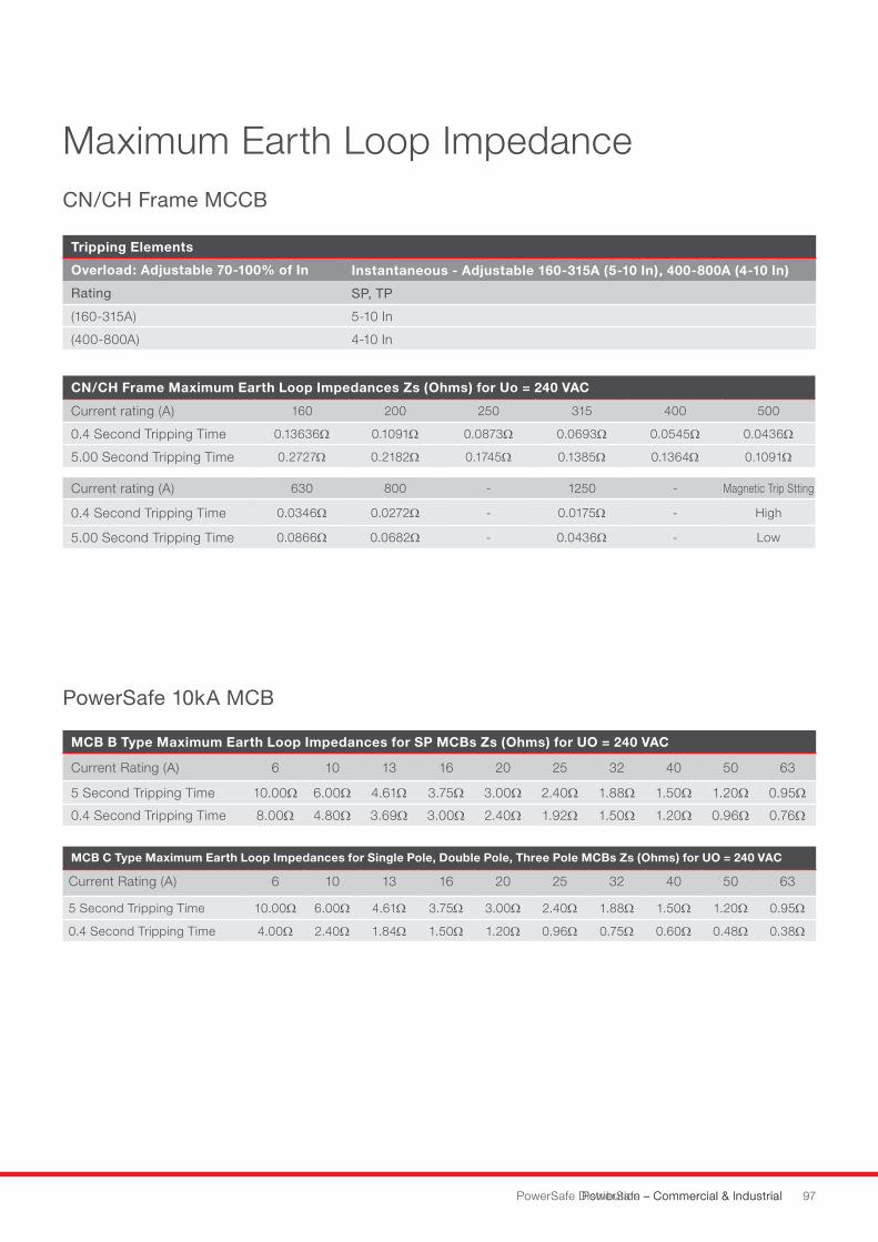
PowerSafe – Commercial & Industrial 97PowerSafe Distribution – Commercial & Industrial
Maximum Earth Loop Impedance
PowerSafe 10kA MCB
CN/CH Frame MCCB
CN/CH Frame Maximum Earth Loop Impedances Zs (Ohms) for Uo = 240 VAC
Current rating (A) 160 200 250 315 400 500
0.4 Second Tripping Time 0.13636Ω 0.1091Ω 0.0873Ω 0.0693Ω 0.0545Ω 0.0436Ω
5.00 Second Tripping Time 0.2727Ω 0.2182Ω 0.1745Ω 0.1385Ω 0.1364Ω 0.1091Ω
Current rating (A) 630 800 - 1250 - Magnetic Trip Stting
0.4 Second Tripping Time 0.0346Ω 0.0272Ω - 0.0175Ω - High
5.00 Second Tripping Time 0.0866Ω 0.0682Ω - 0.0436Ω - Low
Tripping Elements
Overload: Adjustable 70-100% of In Instantaneous - Adjustable 160-315A (5-10 In), 400-800A (4-10 In)
Rating SP, TP
(160-315A) 5-10 In
(400-800A) 4-10 In
MCB B Type Maximum Earth Loop Impedances for SP MCBs Zs (Ohms) for UO = 240 VAC
Current Rating (A) 6 10 13 16 20 25 32 40 50 63
5 Second Tripping Time 10.00Ω 6.00Ω 4.61Ω 3.75Ω 3.00Ω 2.40Ω 1.88Ω 1.50Ω 1.20Ω 0.95Ω
0.4 Second Tripping Time 8.00Ω 4.80Ω 3.69Ω 3.00Ω 2.40Ω 1.92Ω 1.50Ω 1.20Ω 0.96Ω 0.76Ω
MCB C Type Maximum Earth Loop Impedances for Single Pole, Double Pole, Three Pole MCBs Zs (Ohms) for UO = 240 VAC
Current Rating (A) 6 10 13 16 20 25 32 40 50 63
5 Second Tripping Time 10.00Ω 6.00Ω 4.61Ω 3.75Ω 3.00Ω 2.40Ω 1.88Ω 1.50Ω 1.20Ω 0.95Ω
0.4 Second Tripping Time 4.00Ω 2.40Ω 1.84Ω 1.50Ω 1.20Ω 0.96Ω 0.75Ω 0.60Ω 0.48Ω 0.38Ω
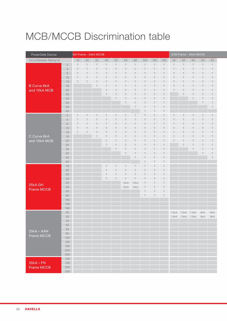
98 HAVELLS
MCB/MCCB Discrimination table
PowerSafe Device GH Frame – 25kA MCCB AAN Frame – 25kA MCCB FN Frame – 35kA MCCB CH Frame – 50kA MCCB D Frame – 50kA MCCB
Circuit Breaker Rating (A) 16 20 32 40 50 63 80 100 125 160 25 32 40 50 63 80 100 125 160 200 250 160A 200A 250A 160 250 320 400 500 630 800 630 800 1000 1250 1600
B Curve 6kA and 10kA MCB
2 T T T T T T T T T T T T T T T T T T T T T T T T T T T T T T T T T T T T
4 T T T T T T T T T T T T T T T T T T T T T T T T T T T T T T T T T T T T
6 T T T T T T T T T T T T T T T T T T T T T T T T T T T T T T T T T T T T
10 T T T T T T T T T T T T T T T T T T T T T T T T T T T T T T T T T T T T
13 T T T T T T T T T T T T T T T T T T T T T T T T T T T T T T T T T T T T
16 T T T T T T T T T T T T T T T T T T T T T T T T T T T T T T T T T T
20 T T T T T T T T T T T T T T T T T T T T T T T T T T T T T T T T T
25 T T T T T T T T T T T T T T T T T T T T T T T T T T T T T T T T
32 T T T T T T T T T T T T T T T T T T T T T T T T T T T T T T
40 T T T T T T T T T T T T T T T T T T T T T T T T T T T T
50 T T T T T T T T T T T T T T T T T T T T T T T T T T
63 T T T T T T T T T T T T T T T T T T T T T T T T
C Curve 6kA and 10kA MCB
2 T T T T T T T T T T T T T T T T T T T T T T T T T T T T T T T T T T T T
4 T T T T T T T T T T T T T T T T T T T T T T T T T T T T T T T T T T T T
6 T T T T T T T T T T T T T T T T T T T T T T T T T T T T T T T T T T T T
10 T T T T T T T T T T T T T T T T T T T T T T T T T T T T T T T T T T T T
13 T T T T T T T T T T T T T T T T T T T T T T T T T T T T T T T T T T T T
16 T T T T T T T T T T T T T T T T T T T T T T T T T T T T T T T T T T
20 T T T T T T T T T T T T T T T T T T T T T T T T T T T T T T T T T
25 T T T T T T T T T T T T T T T T T T T T T T T T T T T T T T T T
32 T T T T T T T T T T T T T T T T T T T T T T T T T T T T T T
40 T T T T T T T T T T T T T T T T T T T T T T T T T T T T
50 T T T T T T T T T T T T T T T T T T T T T T T T T T
63 T T T T T T T T T T T T T T T T T T T T T T T T
25kA GH Frame MCCB
16 T T T T T T T T T T T T T T T T T T T T T T T T T
20 T T T T T T T T T T T T T T T T T T T T T T T T T
25 T T T T T T T T T T T T T T T T T T T T T T T T T
32 T T T T T T T 14kA 14kA 14kA T T T T T T T T T T T T T T T
40 10kA 10kA T T T 14kA 14kA 14kA T T T T T T T T T T T T T T T
50 10kA 10kA T T T 14kA 14kA 14kA T T T T T T T T T T T T T T T
63 T T T 14kA 14kA 14kA T T T T T T T T T T T T T T T
80 T T T 13kA 14kA 14kA T T T T T T T T T T T T T T T
100 12.5kA 14kA 14kA T T T T T T T T T T T T T T T
125 12.5kA 13kA 13kA T T T T T T T T T T T T T T T
160 12.5kA 13kA 14kA 15kA T T T T T T T T T
25kA – AAN Frame MCCB
25 7.5kA 7.5kA 7.5kA 8kA 8kA 10kA 10kA 10kA 14kA 14kA 14kA T T T T T T T T T T T T T T T
32 7.5kA 7.5kA 7.5kA 8kA 8kA 10kA 10kA 10kA 14kA 14kA 14kA T T T T T T T T T T T T T T T
40 10kA 10kA 10kA 14kA 14kA 14kA T T T T T T T T T T T T T T T
50 10kA 10kA 10kA 14kA 14kA 14kA T T T T T T T T T T T T T T T
63 10kA 10kA 10kA 14kA 14kA 14kA T T T T T T T T T T T T T T T
80 14kA 14kA 14kA T T T T T T T T T T T T T T T
100 13kA 13kA 13kA T T T T T T T T T T T T T T T
125 13kA 13kA 13kA T T T T T T T T T T T T T T T
160 T T T T T T T T T T T
200 T T T T T T T T T T T
250 T T T T T T T T T T
35kA – FN Frame MCCB
125 T T T T T T T T T T T T T T T T T T
160 T T T T T T T T T T T
200 T T T T T T T T T T T
250 T T T T T T T T T T
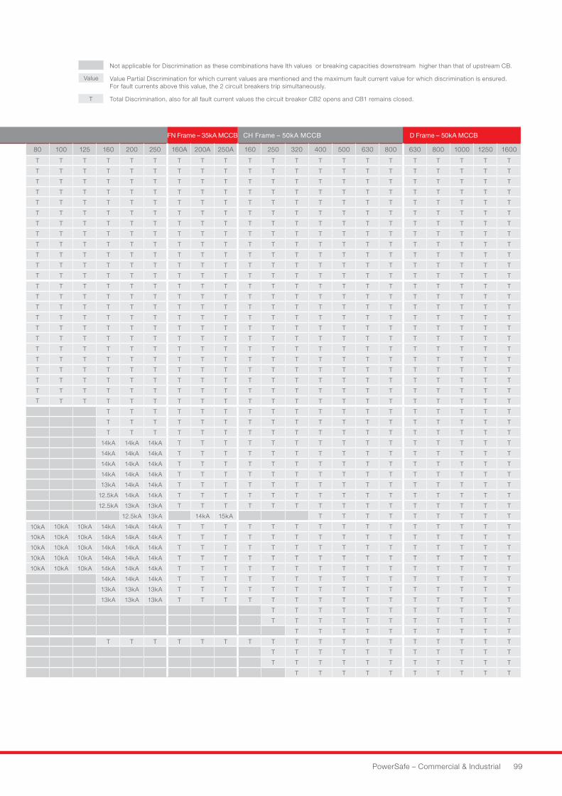
PowerSafe – Commercial & Industrial 99
PowerSafe Device GH Frame – 25kA MCCB AAN Frame – 25kA MCCB FN Frame – 35kA MCCB CH Frame – 50kA MCCB D Frame – 50kA MCCB
Circuit Breaker Rating (A) 16 20 32 40 50 63 80 100 125 160 25 32 40 50 63 80 100 125 160 200 250 160A 200A 250A 160 250 320 400 500 630 800 630 800 1000 1250 1600
B Curve 6kA and 10kA MCB
2 T T T T T T T T T T T T T T T T T T T T T T T T T T T T T T T T T T T T
4 T T T T T T T T T T T T T T T T T T T T T T T T T T T T T T T T T T T T
6 T T T T T T T T T T T T T T T T T T T T T T T T T T T T T T T T T T T T
10 T T T T T T T T T T T T T T T T T T T T T T T T T T T T T T T T T T T T
13 T T T T T T T T T T T T T T T T T T T T T T T T T T T T T T T T T T T T
16 T T T T T T T T T T T T T T T T T T T T T T T T T T T T T T T T T T
20 T T T T T T T T T T T T T T T T T T T T T T T T T T T T T T T T T
25 T T T T T T T T T T T T T T T T T T T T T T T T T T T T T T T T
32 T T T T T T T T T T T T T T T T T T T T T T T T T T T T T T
40 T T T T T T T T T T T T T T T T T T T T T T T T T T T T
50 T T T T T T T T T T T T T T T T T T T T T T T T T T
63 T T T T T T T T T T T T T T T T T T T T T T T T
C Curve 6kA and 10kA MCB
2 T T T T T T T T T T T T T T T T T T T T T T T T T T T T T T T T T T T T
4 T T T T T T T T T T T T T T T T T T T T T T T T T T T T T T T T T T T T
6 T T T T T T T T T T T T T T T T T T T T T T T T T T T T T T T T T T T T
10 T T T T T T T T T T T T T T T T T T T T T T T T T T T T T T T T T T T T
13 T T T T T T T T T T T T T T T T T T T T T T T T T T T T T T T T T T T T
16 T T T T T T T T T T T T T T T T T T T T T T T T T T T T T T T T T T
20 T T T T T T T T T T T T T T T T T T T T T T T T T T T T T T T T T
25 T T T T T T T T T T T T T T T T T T T T T T T T T T T T T T T T
32 T T T T T T T T T T T T T T T T T T T T T T T T T T T T T T
40 T T T T T T T T T T T T T T T T T T T T T T T T T T T T
50 T T T T T T T T T T T T T T T T T T T T T T T T T T
63 T T T T T T T T T T T T T T T T T T T T T T T T
25kA GH Frame MCCB
16 T T T T T T T T T T T T T T T T T T T T T T T T T
20 T T T T T T T T T T T T T T T T T T T T T T T T T
25 T T T T T T T T T T T T T T T T T T T T T T T T T
32 T T T T T T T 14kA 14kA 14kA T T T T T T T T T T T T T T T
40 10kA 10kA T T T 14kA 14kA 14kA T T T T T T T T T T T T T T T
50 10kA 10kA T T T 14kA 14kA 14kA T T T T T T T T T T T T T T T
63 T T T 14kA 14kA 14kA T T T T T T T T T T T T T T T
80 T T T 13kA 14kA 14kA T T T T T T T T T T T T T T T
100 12.5kA 14kA 14kA T T T T T T T T T T T T T T T
125 12.5kA 13kA 13kA T T T T T T T T T T T T T T T
160 12.5kA 13kA 14kA 15kA T T T T T T T T T
25kA – AAN Frame MCCB
25 7.5kA 7.5kA 7.5kA 8kA 8kA 10kA 10kA 10kA 14kA 14kA 14kA T T T T T T T T T T T T T T T
32 7.5kA 7.5kA 7.5kA 8kA 8kA 10kA 10kA 10kA 14kA 14kA 14kA T T T T T T T T T T T T T T T
40 10kA 10kA 10kA 14kA 14kA 14kA T T T T T T T T T T T T T T T
50 10kA 10kA 10kA 14kA 14kA 14kA T T T T T T T T T T T T T T T
63 10kA 10kA 10kA 14kA 14kA 14kA T T T T T T T T T T T T T T T
80 14kA 14kA 14kA T T T T T T T T T T T T T T T
100 13kA 13kA 13kA T T T T T T T T T T T T T T T
125 13kA 13kA 13kA T T T T T T T T T T T T T T T
160 T T T T T T T T T T T
200 T T T T T T T T T T T
250 T T T T T T T T T T
35kA – FN Frame MCCB
125 T T T T T T T T T T T T T T T T T T
160 T T T T T T T T T T T
200 T T T T T T T T T T T
250 T T T T T T T T T T
Not applicable for Discrimination as these combinations have Ith values or breaking capacities downstream higher than that of upstream CB.
Value Value Partial Discrimination for which current values are mentioned and the maximum fault current value for which discrimination is ensured. For fault currents above this value, the 2 circuit breakers trip simultaneously.
T Total Discrimination, also for all fault current values the circuit breaker CB2 opens and CB1 remains closed.

Havells Sylvania UK LtdAvis Way, NewhavenEast Sussex BN9 0ED
Customer Service: 0800 440 2478
CAT
5857
havells.co.uk