Embed Size (px)
Citation preview

A Brief Introduction toEngineering Graphics
Will Durfee & Tim KowalewskiDepartment of Mechanical Engineering
University of Minnesota

Opening comments
• Engineering graphics is the method for documenting a design
• Mechanical engineering students must be familiar with standards of engineering graphics as it is expected in industry
• This set of slides introduces some of the basics, but is not comprehensive
• For more, see• Engineering Graphics section on the Resources page of the
course ME2011 website• Any engineering graphics textbook

1. SHAPE2. SIZE3. MATERIAL4. TOLERANCE5. FINISH
Documenting a part requires...

Engineering drawings
• Universal language• Conventions (drawing grammar) simplify
communication; your drawing is at risk if you defy• CAD packages make formal drawing easy…if you
follow the conventions• The machinist will laugh at you behind your back if
you show up with a non-standard drawing

Multiview drawings
FRONT RIGHT SIDE
TOP
“3rd angle projection”

Multiview drawings
FRONT RIGHT SIDE
TOP
“3rd angle projection”
Views MUST align

Multiview drawings
FRONT RIGHT SIDE
TOP
“3rd angle projection”You walk around part to the right (US)
Rotate the part to the right (Europe)
Views MUST align

The Glass Box:
Bertoline, Engineering Graphics

Alignment & Orientation are preserved…
Bertoline, Engineering Graphics

Six Principle views: obey layout

Basic lines (the “alphabet of lines”)
Object line
Hidden line
Center line
Dimension line

HIDDEN LINES
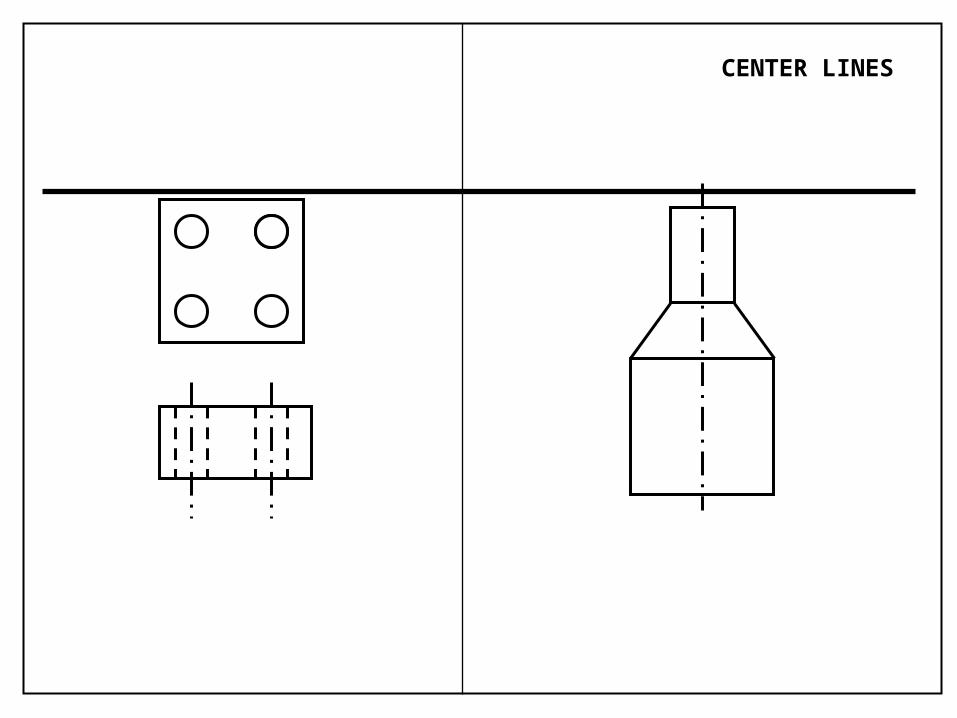
CENTER LINES

Interpreting Center Lines
Enough Info? Enough Info?

COULD BE THIS...

OR THIS
Centerlines imply symmetry, NOT revolution per se

HERE, ONLY 2 VIEWS NEEDED(Correct drawing)

Find The Mistakes!

Find The Mistakes!

FRONT

FIND THE MISTAKES!
FRONT

CORRECT DRAWING

SECTIONS
A A
YES NO

Working with person sitting next to you copy this and draw the TOP VIEW

Working with person sitting next to you copy this and draw the TOP VIEW
Possible Geometries

Working with person sitting next to you, sketch the Section View

Correct Section Views
OK
OK
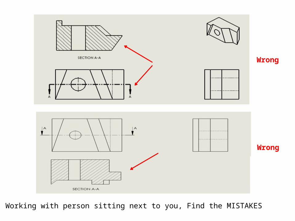
Working with person sitting next to you, Find the MISTAKES
Wrong
Wrong

Working with person sitting next to you, sketch the Section View

REVOLVED SECTION
Preferred “True” section
DIMENSIONING1. SHAPE2. SIZE3. MATERIAL4. TOLERANCE AND FINISH

Dimensioning
5
3
5
3
• Conventions exist for choice and placement
• Not too many and not too few
• Never should measure off drawing with a ruler

Under/Over Dimensioning
3
5
5
3
5
3
5
2

Dimensioning rules:…find the mistakes.
3
5
5
3
5
3
5
2

Dimensioning guidelines
3
5
5
3
5
3
5
2
1. Don’t overdefine or underdefine the object. [MOST IMPORTANT]2. Dimension to the visible contour or shape of the feature / Don’t dimension to hidden lines.4. Don’t dimension to object lines (model edges), use extension lines. 5. Don’t overlap a dimension and the model. Place dimensions awayfrom the model’s surface. 6. Don’t cross extension lines if possible.7. Group dimensions when possible unless it become difficult to read.8. Place dimensions on the side of the view were adjacent views exist (for easy referencing).

Design Detail½” thick aluminum blockWhich is more expensive: A or B and why?
4.0 4.1
A B
6.0 6.0

Dimensioning Choices & Design Intent
6
2
2
6
6
4
2
6
A B
If change width of block to 8, what happens to the hole location?

Placement conventions
2.00
3.00
small gap
letters about 1/8" tall
dimension line
extension line
dimension
arrow touches
a little extended
about 3/8" from part about 1/4" between dimensions
6.2

Lettering: 1 or 2 directions only
.50
.50 .50 .50
1.00.50
.50
OK OK NO

Extension Lines
1.000
1.000
2.007
2.000
no gaps .375 .500
no break in line

All on one side
YES NO
.913
2.739
.907 .913 .907
2.739

Dimensioning Rounds
0.25
R 0.125
0.75
Place dimension on view that shows the circleShow diameter rather than radius


TOLERANCES
www.efunda.com/processes/machining/drill_press.cfm
www.efunda.com/processes/machining/drill.cfm

Tolerances
• Matter because parts cannot be made to an exact dimension
• Must specify dimension tolerance so that every part A fits every part B
• Higher tolerance = higher cost• A ½ inch hole made on an ordinary drill press gives
you a hole in the range 0.496 to 0.504 (+/- 0.004). For higher precision, drill undersize and use a reamer…but it will cost you more and take longer to fabricate.

½ inch drill bit: +/- .0040
½ inch reamer: +.0003, -.0000

LEGOS !• You can combine six 8-stud bricks of the same color 102,981,500 different ways
• 91% of all households with children in Denmark own LEGO products
• During the period 1949-1990, 110,000,000,000 (110 billion) LEGO elements were molded
• Bayer Corporation's Polymers Division is the official supplier of ABS plastic to the LEGO group.
• Exact specifications of the Bayer resin supplied to the LEGO Group are a closely held secret.
• Dimension tolerance of mold is 0.005 mm (0.0002 inch)!
9.6
1.7
8
D 5
ABS plastic

Representing tolerances
3.000
1.000
3.0052.995
1.005.995
3.000±.005
1.000±.005
3.000+.005-.005
1.000+.005-.005

Tolerance stack-up
3.0 ± .05 5 high stack
?14.7515.25
What is min and max height of stack?
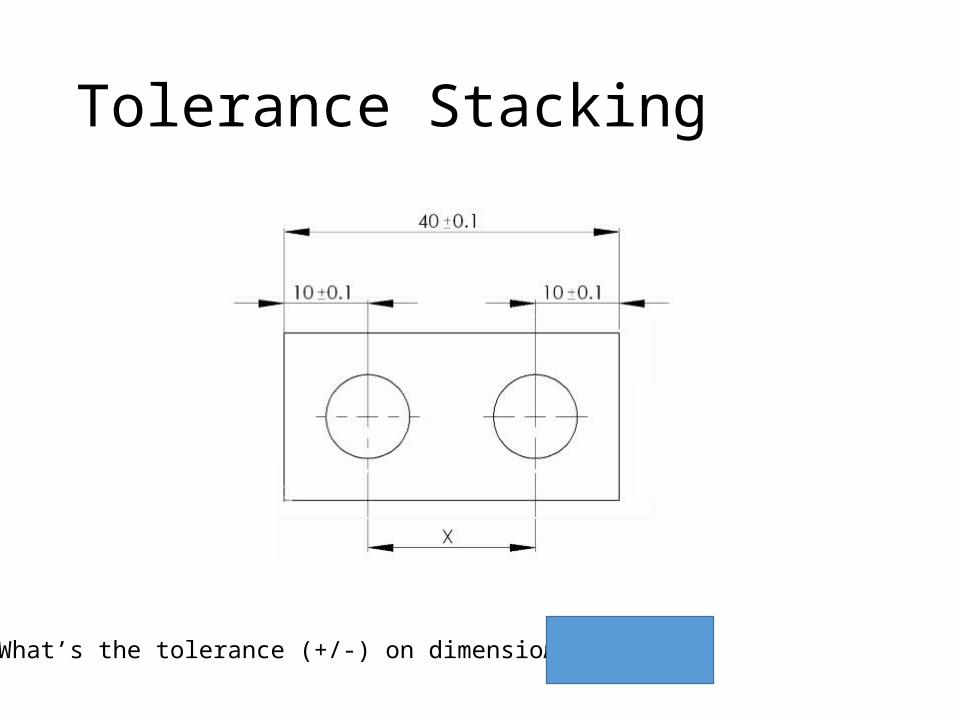
Tolerance Stacking
What’s the tolerance (+/-) on dimension x? Ans: +/- 0.3

Chain or Baseline Dimensioning?… You decide
1.0±.1 1.0±.12.0±.1 1.0±.1
3.0±.1
4.0±.1

Chain or Baseline Dimensioning
1.0±.1 1.0±.12.0±.1 1.0±.1
3.0±.1
4.0±.1

Holes and shafts
.626
.625.623.622
holeshaft
.626
.625.623.622
1. Will all shafts fit into all holes?
2. What is maximum clearance?

ANSI standards for shaft & holes.626.625
.623
.622
Clearance Shaft smaller than hole for all shafts and holes
Interference Shaft larger than hole for all shafts and holesTransition Smallest shaft fits in largest hole
Running/Sliding RC1 (fit together, no play) to RC9 (fit loosely)
Force/shrink FN1 (light drive and pressure) to FN5 (high stresses and pressures)
…and others Like Locational, etc.
Basic hole Use nominal size of hole as starting point
Basic shaft Use nominal size of shaft as starting point

Preferred Fit Example…

“Basic Hole” Tolerancing Example
1.0000+ .0012- .0000
1.0000- .0008
- .0016
Drawing shows 1 in. nominal, ANSI RC4 clearance fit
“Basic Hole” means smallest possible hole = nominal, then size shaft for clearance
RC4 clearance = [0.0008, 0.0028] = [smallest hole-largest shaft,
largest hole - smallest shaft]

Title block information for tolerance
ALL DIMENSIONS IN INCHES
HOLD ALL DIMENSIONS TO ± 0.010 UNLESS SPECIFIED
Dimension ToleranceX.X ± 0.1X.XX ± 0.05X.XXX ± 0.001

Design DetailBent aluminum sheet, 1/16” thickA or B: Which is more expensive and why?
A
B4.0 +-
0.003
0.030{

1.00 ±.05
1.000 ±.005
1.0000 ±.00005
1.00 ±.075 $
$
$$
$$$$
Tolerance vs. Cost

Manufacturing Tolerances

Geometric Dimensioning and Tolerancing (GD&T)

Traditional tolerancing is ambiguous
3.000±.005
1.000 ±.005
? ?

Ambiguity…
.25 ± .01
.25 ± .01
+ +
Square deviation Circular deviation

Geometric Dimensioning and Tolerancing
.25
.125 +/- .002
.01
• Ideal position of hole. .25, is marked with box and no +/- notation.• Feature control box shows how close hole is to exact; within circular tolerance zone with diameter .01

Geometric Dimensioning and Tolerancing
.25

GD&T Resources
ME2011 website:
https://sites.google.com/a/umn.edu/me2011/resources
• Efunda tutorial:http://www.efunda.com/designstandards/gdt

Threaded FastenersWhat they are and how to indicate on a drawing
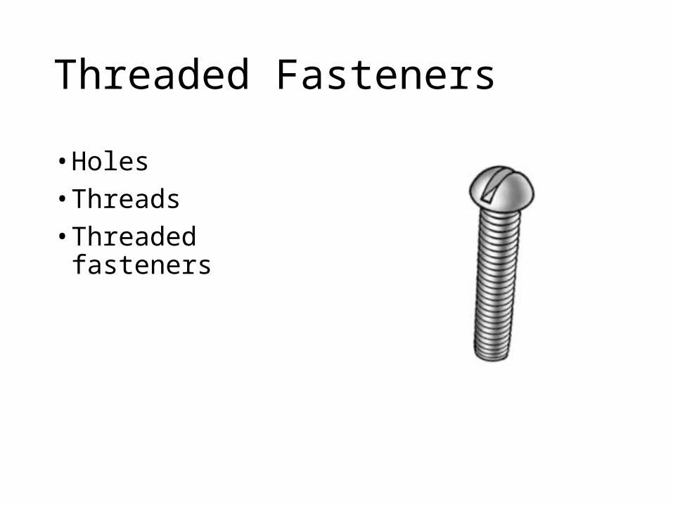
Threaded Fasteners
• Holes • Threads • Threaded fasteners

Holes
DEPTH0.75 REF
19 DRILL – 0.75 DEEPor
O .166 . 75
Pix from www.mcmaster.comunless noted

Thru holes
19 DRILL – THRUor
O .166

Threads
http://www.americanfastener.com/technical/thread_terminology.asphttp://www.machinist.org/harvard_cotreau/mshop6.html

Threaded Fasteners (screws, bolts)
• Specify diameter, thread, length, head
1/4-20 x 1, RHMS
ROUND HEADMACHINE SCREW1" LONG
20 THREADSPER INCH
1/4" DIA
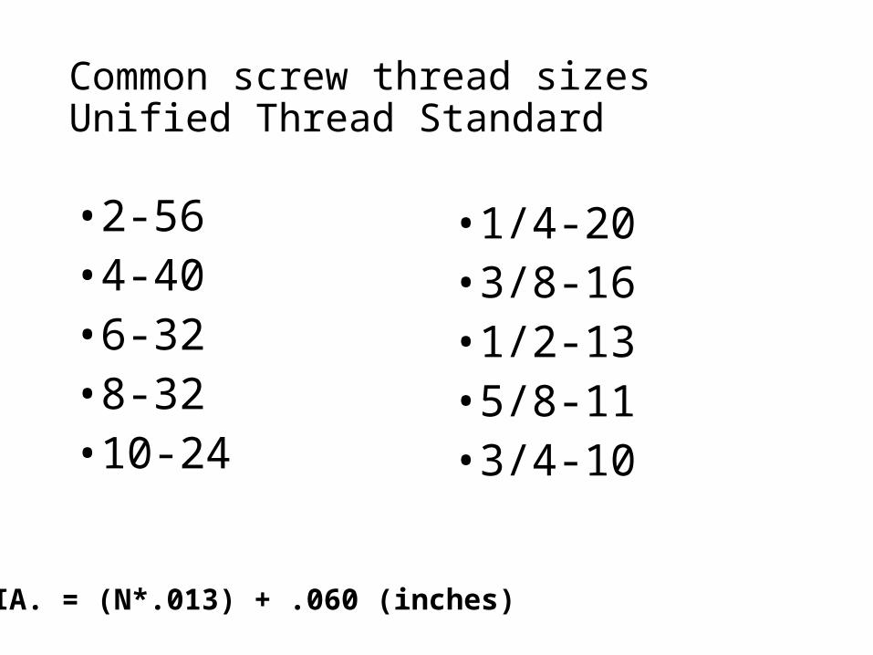
Common screw thread sizesUnified Thread Standard
• 2-56• 4-40• 6-32• 8-32• 10-24
• 1/4-20 • 3/8-16• 1/2-13• 5/8-11• 3/4-10
DIA. = (N*.013) + .060 (inches)

Alternate Thread Callout

Head shapes
Pan
Flat
Round
Cap screw
Socket head cap screw (SHCS)
Set screw
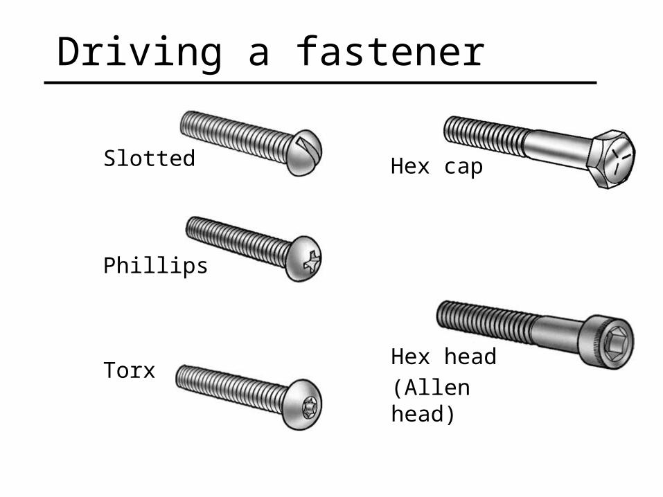
Driving a fastener
Slotted
Phillips
Torx
Hex cap
Hex head(Allen head)

McMaster-Carrwww.mcmaster.com

Name the Fastener:

Name the Fastener:
Socket Head Cap Screw
Socket Head Cap Screwwith counterbore

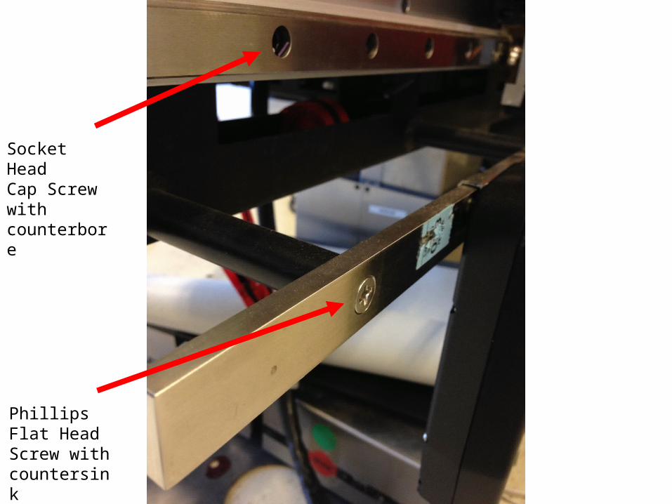
Socket Head Cap Screw with counterbore
Phillips Flat Head Screw with countersink


Countersunk,Phillips Flat head
Set Screw

Convention for screws
“SCHEMATIC” “SIMPLIFIED”

Convention for threaded holes
FRONT
TOP
FRONTSECTION
6-32 THRU

Blind threaded holes1/2 – 13 x 1.325 DEEP
THREAD DEPTH
DRILL DEPTH
.4219 1.501/2 – 13 1.325

Countersunk holes .562 – 82O CSK, 1.125
.562 1.125 x 82O

Counterbored holes 19 DRILL – 29 CBORE, 14 DEEP
C-BORE DEPTH
19 29 14


Other Items for Drawings

Leaders & notes
FINISH TOP SURFACE SMOOTH
NOTE B
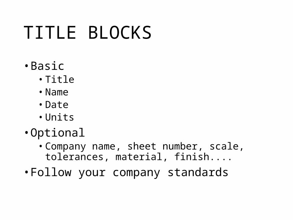
TITLE BLOCKS
• Basic• Title• Name• Date• Units
• Optional• Company name, sheet number, scale, tolerances,
material, finish....
• Follow your company standards

MY PARTW. DURFEE 10/2/2014ALL DIMENSIONS IN INCHES
A basic title block

A title block with more information

www.classic-components.co.ukA title block using a company template

Production Drawings
MODELSKETCHESSKETCHES
SKETCHES
ASSEMBLY
DETAILDETAIL
DETAILDETAIL
DETAIL
BOM MANUALS MFG PROCESS
Many types of drawings can be produced fromthe CAD database