Embed Size (px)
Citation preview
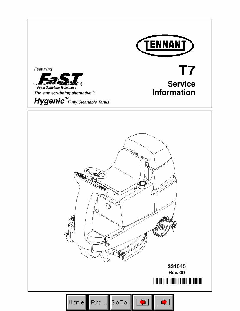
T7
331045Rev. 00
ServiceInformation
*331045*
®
Hygenic Fully Cleanable Tanks
Featuring
The safe scrubbing alternativet
t

This manual provides service information for the TENNANT Model T7.
This machine will provide excellent service. However, the best results will be obtained at minimumcosts if:
D The machine is operated with reasonable care.D The machine is maintained regularly -- per the maintenance instructions provided.D The machine is maintained with TENNANT supplied or approved parts.
Manual Number -- 331045
Revision: 00
Published: 12--04
Tennant CompanyPO Box 1452Minneapolis, MN 55440Phone: (800) 553--8033 or (763) 513--2850www.tennantco.com
FaST Foam Scrubbing Technology logo is a United States registered trademark of Tennant Company.
Copyright E 2003 TENNANT, Printed in U.S.A.
Table of Contents
Electrical Troubleshooting Information ...................................................................................... 1 Commonly Used Electrical Symbols & Terms........................................................................ 2 Ladder Schematic .................................................................................................................. 3 Wire Harness Group............................................................................................................... 5 Key OFF, Operator NOT on Seat........................................................................................... 9 Key OFF, Battery Charger Plugged In ................................................................................. 10 Key ON, Operator on Seat ................................................................................................... 11 Tank Level Sensors.............................................................................................................. 12 Horn & Hour Meter Systems ................................................................................................ 13 Propel Forward System........................................................................................................ 14 Propel Reverse System........................................................................................................ 15 Braking System .................................................................................................................... 16 Scrub Head & Squeegee Actuator Systems ........................................................................ 17 Scrub Brush Motors System................................................................................................. 19 Vacuum Fan System............................................................................................................ 20 FaST System........................................................................................................................ 21 Conventional Solution System................................................................................................. 22 LED Locations & Descriptions.............................................................................................. 23 Operational Modes & Interlocks ........................................................................................... 24 Diagnostic & Fault Alarms.................................................................................................... 25 Alarm Codes ..................................................................................................................... 25 High Current Faults ........................................................................................................... 25 Diagnostic & Configuration Modes....................................................................................... 26 Display Software Revision Mode ......................................................................................... 27 Self Test Mode ..................................................................................................................... 28 Input Display Mode............................................................................................................... 29 Manual Mode........................................................................................................................ 30 Propel / Brake Diagnostics ................................................................................................... 31 Battery Select Mode & Voltage Levels................................................................................. 32 Battery Select Mode.......................................................................................................... 32 Voltage Levels................................................................................................................... 32 Reverse Alarm & Propel Speed Select Modes .................................................................... 33 Reverse Alarm Select Mode ............................................................................................. 33 Propel Speed Select Mode ............................................................................................... 33 Inputs & Outputs Table......................................................................................................... 34 Torque Standard...................................................................................................................... 35 Inch Fasteners...................................................................................................................... 35 METRIC Fasteners............................................................................................................... 37 Nylon Insert Lock Nuts ......................................................................................................... 39 Nut-Hex Light THIN .............................................................................................................. 39 Wheel Bolt and Nuts............................................................................................................. 40 Wheel Bearing Adjustment................................................................................................... 40 Tightening Nuts on Tapered Shafts ..................................................................................... 41 Shoulder Bolts ...................................................................................................................... 42 Taper Lockr Bushings .......................................................................................................... 43 Sequence Tightening ........................................................................................................... 44
i

ii

T7
ELECTRICALTroubleshooting Information
BEFORE CONDUCTING TESTS:
DURING TESTS:
* Read and Follow ALL Safety Warnings and Precautions in Operator's Manual
* Always use an ESD (Electrostatic Discharge) strap when working near the Control Board
* Be cautious when working near Control Board – Battery voltage is always present, even with Key OFF
* Always unplug Positive Battery Cable when removing or replacing components
* Call Technical Services if Diagnostic Time Exceeds One Hour With Unknown Cause or Course of Action
NOTE:Troubleshooting charts may be shown with optional equipment. The optional equipment may not be specified in these charts. Some machines may not be equipped with all components shown.
2005.01.05 T7ETI REV 00
1
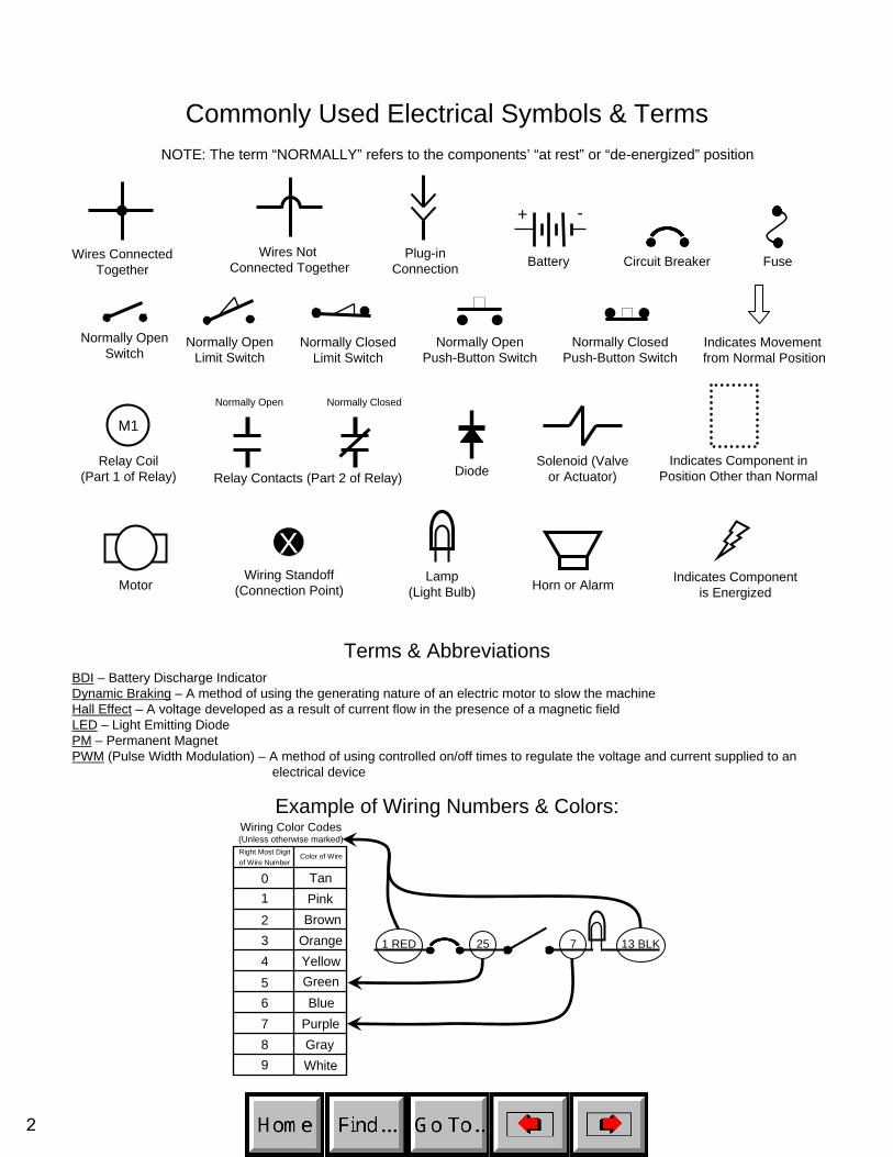
Commonly Used Electrical Symbols & TermsNOTE: The term “NORMALLY” refers to the components’ “at rest” or “de-energized” position
+ -
Battery Fuse
Normally ClosedPush-Button Switch
Normally OpenSwitch
Wires ConnectedTogether
Normally OpenPush-Button Switch
Plug-inConnection
Wires Not Connected Together Circuit Breaker
Indicates Movement from Normal Position
Normally OpenLimit Switch
Normally ClosedLimit Switch
Indicates Component inPosition Other than NormalRelay Contacts (Part 2 of Relay)
Normally Open Normally Closed
Solenoid (Valveor Actuator)
M1
Relay Coil(Part 1 of Relay) Diode
Lamp(Light Bulb)
Indicates Componentis EnergizedMotor
XWiring Standoff
(Connection Point) Horn or Alarm
Terms & AbbreviationsBDI – Battery Discharge IndicatorDynamic Braking – A method of using the generating nature of an electric motor to slow the machineHall Effect – A voltage developed as a result of current flow in the presence of a magnetic field LED – Light Emitting DiodePM – Permanent MagnetPWM (Pulse Width Modulation) – A method of using controlled on/off times to regulate the voltage and current supplied to an
electrical device
Wiring Color Codes(Unless otherwise marked)
01
23456789
TanPinkBrown
OrangeYellowGreenBlue
PurpleGrayWhite
Right Most Digitof Wire Number
Color of Wire
Example of Wiring Numbers & Colors:
1 RED 25 7 13 BLK
2
12
3
4
5
1021038
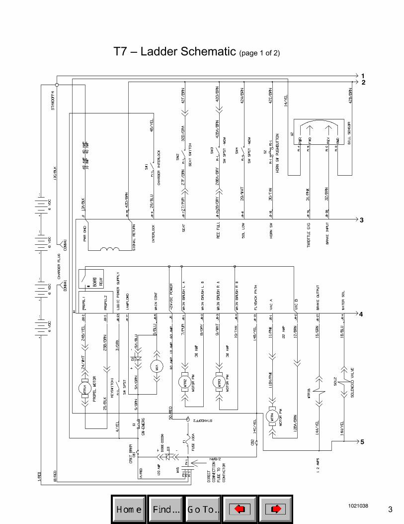
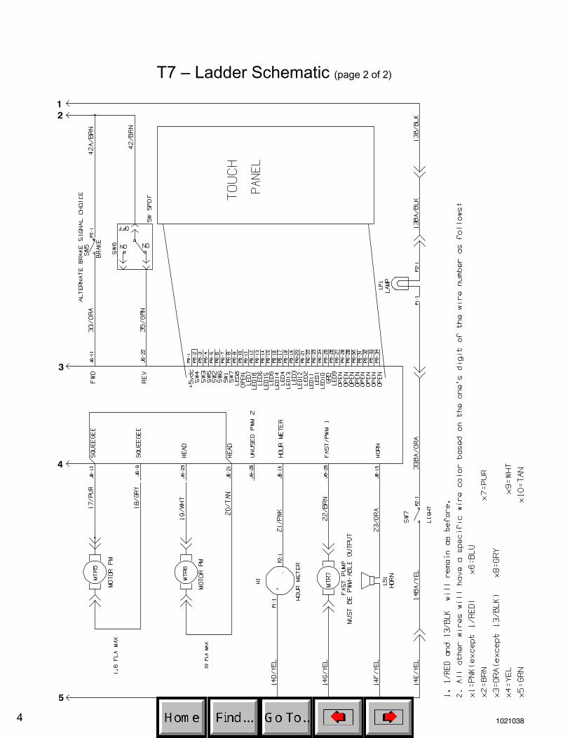
T7 – Ladder Schematic (page 1 of 2)
3
12
3
4
5
1021038
T7 – Ladder Schematic (page 2 of 2)
4
1
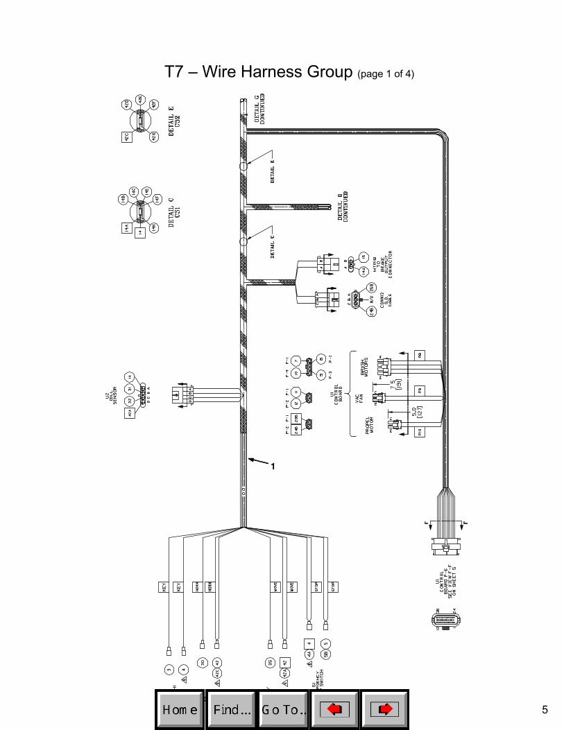
T7 – Wire Harness Group (page 1 of 4)
5

1
T7 – Wire Harness Group (page 2 of 4)
6

1
T7 – Wire Harness Group (page 3 of 4)
7
2
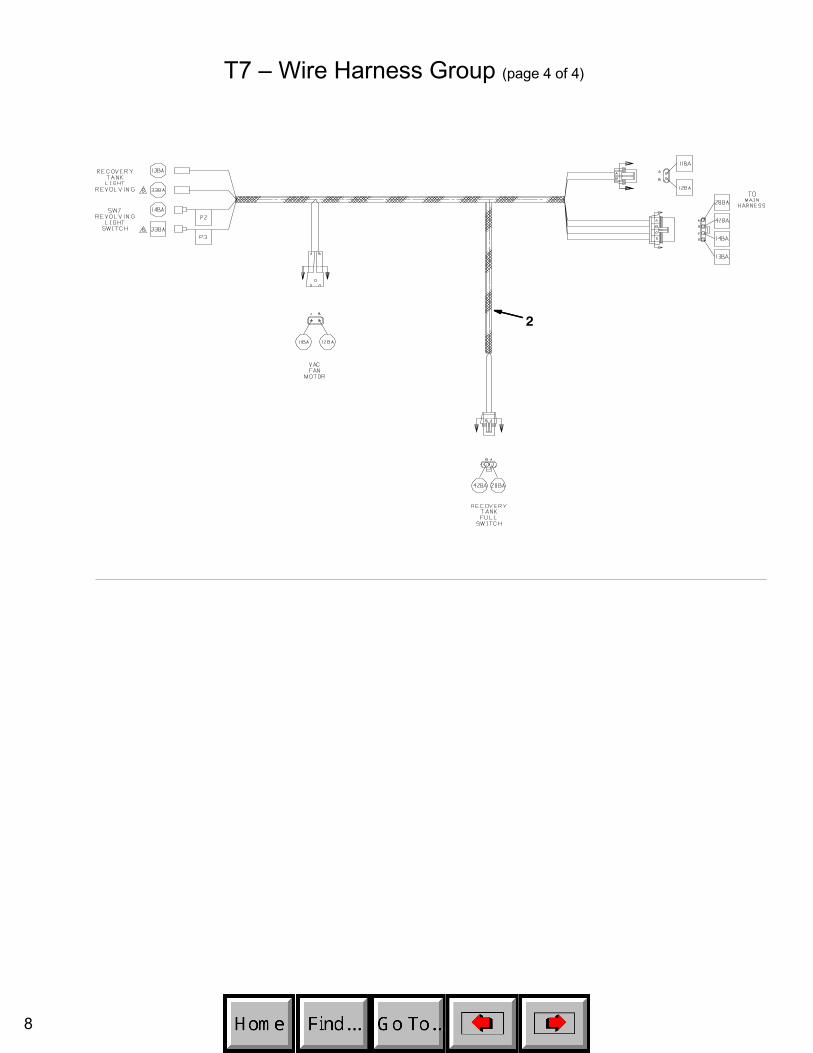
T7 – Wire Harness Group (page 4 of 4)
8

T7 - Key OFF, Operator NOT on Seat
D3
1 RED 13 BLK
14
13 BLK
2
POS
RIBBON CABLE CONNECTOR P6
CONTROL BOARD
STANDOFF 2
+ -6 VDC+ -6 VDC
+ -6 VDC+ -6 VDC
v
M1B
v1 RED
1 RED
CHARGERPLUG
STANDOFF 4
13 BLK
NEG
TOUCH PANEL
50 RED
F1 100 A
S1
M1A
D1
CB15 A
CB2 15 A
KEYSWITCH
CHARGER INTERLOCK
+
RIBBON CABLE
-
EMERGENCYSTOP SWITCH
X
X
50 RED
2
2 14
MAINCONTACTOR
6
55
5 6
3
26
3
26
4
4
4
4 4
PIN J6-17
PIN J6-5
PIN J6-24
PIN J6-6
PIN J6-1314
1 RED
1 RED 13 BLK
50 RED
1 RED
13 BLKPOST J11 POST J7
SW1 SW2SEAT
SWITCH
PIN J6-35
PIN J6-7
42
42
27
LOGIC GROUND
32ORG27
GRN
Wiring Color Codes(Unless otherwise marked)
01
23456789
TanPinkBrown
OrangeYellowGreenBlue
PurpleGrayWhite
Right Most Digitof Wire Number
Color of Wire
= Battery Negativeor Logic Ground
= Battery Positiveor Positive Output
9
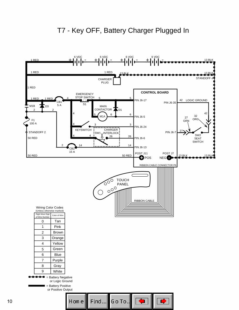
T7 - Key OFF, Battery Charger Plugged In
D3
1 RED 13 BLK
14
13 BLK
2
POS
RIBBON CABLE CONNECTOR P6
CONTROL BOARD
STANDOFF 2
+ -6 VDC+ -6 VDC
+ -6 VDC+ -6 VDC
v
M1B
v1 RED
1 RED
CHARGERPLUG
STANDOFF 4
13 BLK
NEG
TOUCH PANEL
50 RED
F1 100 A
S1
M1A
D1
CB15 A
CB2 15 A
KEYSWITCH CHARGERINTERLOCK
+
RIBBON CABLE
-
EMERGENCYSTOP SWITCH
X
X
50 RED
2
2 14
MAINCONTACTOR
6
55
5 6
3
26
3
26
4
4
4
4 4
PIN J6-17
PIN J6-5
PIN J6-24
PIN J6-6
PIN J6-1314
1 RED
1 RED 13 BLK
50 RED
1 RED
13 BLKPOST J11 POST J7
SW1SW2SEAT
SWITCH
PIN J6-35
PIN J6-7
42
42
27
LOGIC GROUND
32ORG27
GRN
Wiring Color Codes(Unless otherwise marked)
01
23456789
TanPinkBrown
OrangeYellowGreenBlue
PurpleGrayWhite
Right Most Digitof Wire Number
Color of Wire
= Battery Negativeor Logic Ground
= Battery Positiveor Positive Output
10

T7 - Key ON, Operator on Seat
D3
1 RED 13 BLK
14
13 BLK
2
POS
CONTROL BOARD
STANDOFF 2
+ -6 VDC+ -6 VDC
+ -6 VDC
v
M1B
v1 RED
1 RED
CHARGERPLUG
STANDOFF 4
13 BLK
NEG
TOUCH PANEL
50 RED
F1 100 A
S1
M1A
D1
CB15 A
CB2 15 A
KEYSWITCH
+
RIBBON CABLE
-
EMERGENCYSTOP SWITCH
X
X
50 RED
2
2 14
MAINCONTACTOR
6
55
5 6
3
26
3
4
4
4
4
PIN J6-17
PIN J6-5
PIN J6-24
PIN J6-6
PIN J6-1314
1 RED
1 RED 13 BLK
50 RED
1 RED
13 BLK
RIBBON CABLE CONNECTOR P6
POST J11 POST J7
CHARGER INTERLOCK
264 SW1PIN J6-7
27
32ORG
42
4227
GRN
SW2SEAT
SWITCH
PIN J6-35LOGIC GROUNDv
+ -6 VDC
RIGHT SIDEDASH PANEL
O
I
KEYSWITCH
Indicates Componentis Energized
Wiring Color Codes(Unless otherwise marked)
01
23456789
TanPinkBrown
OrangeYellowGreenBlue
PurpleGrayWhite
Right Most Digitof Wire Number
Color of Wire
= Battery Negativeor Logic Ground
= Battery Positiveor Positive Output
11
28
29
42
42
RECOVERY TANK FULL SWITCH
LOGIC GROUND
42
SW3
SW4
D3
1 RED 13 BLK
14
13 BLK
2
POS
CONTROL BOARD
STANDOFF 2
+ -6 VDC+ -6 VDC
+ -6 VDC
v
M1B
v1 RED
1 RED
CHARGERPLUG
STANDOFF 4
13 BLK
NEG
TOUCH PANEL
50 RED
F1 100 A
S1
M1A
D1
CB15 A
CB2 15 A
KEYSWITCH
+
RIBBON CABLE
-
EMERGENCYSTOP SWITCH
X
X
50 RED
2
2 14
MAINCONTACTOR
6
55
5 6
3
26
3
4
4
4
4
PIN J6-17
PIN J6-5
PIN J6-24
PIN J6-6
PIN J6-1314
1 RED
1 RED 13 BLK
50 RED
1 RED
13 BLK
RIBBON CABLE CONNECTOR P6
POST J11 POST J7
CHARGER INTERLOCK
264 SW1
v
+ -6 VDC
T7 – Tank Level Switches
CONDITIONS: key ON
PIN J6-20
PIN J6-35
PIN J6-8
SOLUTION TANK LOW SWITCH
Recovery Tank Full Switch closes when recovery tank is full
Solution Tank Low Switch opens when solution tank is low
Tank Level Switches are ALWAYS in the OPEN position with low orempty tank
Tank Level Switches are ALWAYS in the CLOSED position with full tank
i
Indicates Componentis Energized
Wiring Color Codes(Unless otherwise marked)
01
23456789
TanPinkBrown
OrangeYellowGreenBlue
PurpleGrayWhite
Right Most Digitof Wire Number
Color of Wire
= Battery Negativeor Logic Ground
= Battery Positiveor Positive Output
switch tank full tank empty switch OPEN switch CLOSED indicator
x x Solution Tank Empty LED OFF
x x Solution Tank Empty LED ON
x x Recovery Tank Full LED ON
x x Recovery Tank Full LED OFF
Solution Tank
Recovery Tank
Tank Level Switches Logic Chart
12
T7 – Horn & Hour Meter Systems
1 RED
D3
13 BLK
13 BLKPOS
CONTROL BOARD
STANDOFF 2
+ -6 VDC+ -6 VDC
+ -6 VDC+ -6 VDC
v v1 RED
STANDOFF 4
NEG
TOUCH PANEL
50 RED
F1 100 A
S1
D1
CB15 A
CB2 15 A
KEYSWITCH
RIBBON CABLE
-
EMERGENCYSTOP SWITCH
X
50 RED
14
MAINCONTACTOR
6
55
5 6
3
26
3
4
4
4
4
PIN J6-17
PIN J6-5
PIN J6-24
PIN J6-6
PIN J6-1314
1 RED
50 RED
13 BLK
RIBBON CABLE CONNECTOR P6
POST J11 POST J7
CHARGER INTERLOCK
264 SW1
23
X
+
21
PIN J6-15
PIN J6-14
LEFT SIDEDASH PANEL
Horn pulses ON & OFF when Directional Switch is in REVERSE
Hour Meter is ON only when propelling (forward or reverse), or anytime Squeegee/Vacuum Fan is ON
Horn pulses when a fault is detected (Directional Switch must be in FORWARDPosition) – refer to “Diagnostic/Beep Code” chart
i
CONDITIONS: key ON, operator on seat, in motion OR Vacuum Fan running (for Hour Meter)
2 2
2
30
42PIN J6-35
LOGIC GROUND
42PIN J6-10
LS1HORN
H1HOUR METER
14
2314
14
14
21
RIGHT SIDEDASH PANEL
HORNSWITCH
M1B
M1A
00000
NOTE: Hour Meter is active only when propelling (forward or reverse), ORanytime Squeegee/ Vacuum Fan is active
S2HORN
SWITCH
Indicates Componentis Energized
Wiring Color Codes(Unless otherwise marked)
01
23456789
TanPinkBrown
OrangeYellowGreenBlue
PurpleGrayWhite
Right Most Digitof Wire Number
Color of Wire
= Battery Negativeor Logic Ground
= Battery Positiveor Positive Output
13
13 BLK13 BLK
27
42
42
SW2SEAT
SWITCH
LOGIC GROUND
14
PROPEL PEDALPOSITION SENSOR
31 PROPELSIGNAL POWER
GND 42
14
X
35
PROPELDIRECTION
SWITCH
4242
REVERSE
FORWARD
HALLEFFECTSENSORPROPEL MOTOR
FORWARD
24
25
24 WHT25 BLK
25
14MTR1A
1515
1414
T7 – Propel Forward System
CONDITIONS: key ON, operator on seat, propel pedal depressed
D3
1 RED 13 BLK
POS
CONTROL BOARD
STANDOFF 2
+ -6 VDC+ -6 VDC
+ -6 VDC+ -6 VDC
v v1 RED
STANDOFF 4
TOUCH PANEL
50 RED
F1 100 A
S1
D1
CB15 A
CB2 15 A
KEYSWITCH
RIBBON CABLE
EMERGENCYSTOP SWITCH
X
50 RED
14
MAINCONTACTOR
6
55
5 6
3
26
3
4
4
4
4
PIN J6-17
PIN J6-5
PIN J6-24
PIN J6-6
PIN J6-1314
1 RED
50 RED
RIBBON CABLE CONNECTOR P6
POST J11
CHARGER INTERLOCK
264 SW1
X
+
LEFT SIDEDASH PANEL
2 2
2
M1B
M1A
i
FORWARD
REVERSERIGHT SIDE
DASH PANEL
DIRECTIONALSWITCH
PIN J10-2
PIN J10-1
PIN J6-27
NEG -POST J7
PIN J6-7
PIN J6-35
PIN J6-34
PIN J6-22
14 14
NOTE: Brake Solenoid is energized to releaseparking brake.
32ORG
27GRN
MTR1BBRAKE
SOLENOID
Indicates Componentis Energized
Wiring Color Codes(Unless otherwise marked)
01
23456789
TanPinkBrown
OrangeYellowGreenBlue
PurpleGrayWhite
Right Most Digitof Wire Number
Color of Wire
= Battery Negativeor Logic Ground
= Battery Positiveor Positive Output
= Output that canChange Polarity
Typical Propel Motor Current Draw: 1 to 20 Amps in motion, higher at start-up
Propel Motor Voltage: 0 to 24 VDC - FORWARDApprox. 0 to 17 VDC - REVERSE
Propel Motor is controlled by PWM (Pulse Width Modulation)
The Propel Pedal Position HALL EFFECT Sensor sends a varying voltagesignal (1 to 4 Volts) to control board, based upon position of the propel pedal
NOTE: Refer to the “Propel/Brake Diagnostics” page for more information
SW6
U2
14

25
25 BLK
25
13 BLK13 BLK
27
42
42
SW2SEAT
SWITCH
LOGIC GROUND
14
PROPEL PEDALPOSITION SENSOR
31 PROPELSIGNAL POWER
GND 42
14
X
354242
REVERSE
FORWARD
HALLEFFECTSENSORPROPEL MOTOR
REVERSE
14MTR1A
MTR1BBRAKE
SOLENOID
1515
1414
D3
1 RED 13 BLK
POS
CONTROL BOARD
STANDOFF 2
+ -6 VDC+ -6 VDC
+ -6 VDC
v v1 RED
STANDOFF 4
TOUCH PANEL
50 RED
F1 100 A
S1
D1
CB15 A
CB2 15 A
KEYSWITCH
RIBBON CABLE
EMERGENCYSTOP SWITCH
X
50 RED
14
MAINCONTACTOR
6
55
5 6
3
26
3
4
4
4
4
PIN J6-17
PIN J6-5
PIN J6-24
PIN J6-6
PIN J6-1314
1 RED
50 RED
RIBBON CABLE CONNECTOR P6
POST J11
CHARGER INTERLOCK
264 SW1
X
+
LEFT SIDEDASH PANEL
2 2
2
M1B
M1A
PIN J10-2
PIN J10-1
NEG -POST J7
PIN J6-7
PIN J6-35
PIN J6-34
PIN J6-22
14 14
NOTE: Brake Solenoid is energized to releaseparking brake.
32ORG
27GRN
T7 – Propel Reverse System
CONDITIONS: key ON, operator on seat, propel pedal depressed
FORWARD
REVERSEDIRECTIONAL
SWITCHRIGHT SIDE
DASH PANEL
+ -6 VDC
Indicates Componentis Energized
Wiring Color Codes(Unless otherwise marked)
01
23456789
TanPinkBrown
OrangeYellowGreenBlue
PurpleGrayWhite
Right Most Digitof Wire Number
Color of Wire
= Battery Negativeor Logic Ground
= Battery Positiveor Positive Output
= Output that canChange Polarity
2424 WHT
Typical Propel Motor Current Draw: 1 to 20 Amps in motion, higher at start-up
Propel Motor Voltage: 0 to 24 VDC - FORWARDApprox. 0 to 17 VDC - REVERSE
Propel Motor is controlled by PWM (Pulse Width Modulation)
The Propel Pedal Position HALL EFFECT Sensor sends a varying voltagesignal (1 to 4 Volts) to control board, based upon position of the propel pedal
i
PIN J6-27
PROPELDIRECTION
SWITCH
SW6
U2NOTE: Refer to the “Propel/Brake Diagnostics” page for more information
15

T7 – Braking System
CONDITIONS: key ON, operator on seat, brake pedal depressed
13 BLK13 BLK
27
42
42
SW2SEAT
SWITCH
LOGIC GROUND
14
BRAKE PEDALPOSITION SENSOR
32 BRAKESIGNAL POWER
GND 42
14
HALLEFFECTSENSORPROPEL MOTOR
24
25
24 WHT25 BLK
25
14
1515
1414
D3
1 RED 13 BLK
POS
CONTROL BOARD
STANDOFF 2
+ -6 VDC+ -6 VDC
+ -6 VDC
v v1 RED
STANDOFF 4
TOUCH PANEL
50 RED
F1 100 A
S1
D1
CB15 A
CB2 15 A
KEYSWITCH
RIBBON CABLE
EMERGENCYSTOP SWITCH
X
50 RED
14
MAINCONTACTOR
6
55
5 6
3
26
3
4
4
4
4
PIN J6-17
PIN J6-5
PIN J6-24
PIN J6-6
PIN J6-1314
1 RED
50 RED
RIBBON CABLE CONNECTOR P6
POST J11
CHARGER INTERLOCK
264 SW1
X
+
LEFT SIDEDASH PANEL
2 2
2
M1B
M1A
PIN J10-2
PIN J10-1
NEG -POST J7
PIN J6-7
PIN J6-35
PIN J6-33
14 14
32ORG
27GRN
Indicates Componentis Energized
Wiring Color Codes(Unless otherwise marked)
01
23456789
TanPinkBrown
OrangeYellowGreenBlue
PurpleGrayWhite
Right Most Digitof Wire Number
Color of Wire
= Battery Negativeor Logic Ground
= Battery Positiveor Positive Output
MTR1BBRAKE
SOLENOID
NOTE: Brake Solenoid is DE-energized to apply parking brake. Dynamic Braking will occur before Brake Solenoid is de-energized.
MTR1A
+ -6 VDC
The brake pedal position HALL EFFECT sensor sends a varying voltagesignal (1 to 4 Volts) to control board, based upon position of the brake pedal
Brake Solenoid is DE-energized to apply brake.
Dynamic Braking will occur before Brake Solenoid is de-energized.
i
PIN J6-27
U2NOTE: Refer to the “Propel/Brake Diagnostics” page for more information
16

T7 – Scrub Head & Squeegee Actuator Systems(page 1 of 2)
CONDITIONS: key ON, operator on seat, forward travel, propel pedal depressed, One Step Scrub Button pressed
SQUEEGEE ACTUATOR
17
18
MTR518 17
SCRUB HEAD ACTUATOR
19
20
20 19
Pressing the “One Step Scrub Button” will lower the squeegee and scrub head
Only one actuator will be energized at any given time – squeegee is loweredfirst, then the scrub head
Squeegee actuator uses internal limit switches to stop travel in upward anddownward travel
Scrub head actuator travel is controlled by monitoring actuator current inupward travel and brush motor current in downward travel
Squeegee actuator can also be operated by pressing the “Vacuum Fan/Squeegee Button”, without operating scrub brushes
i
D3
1 RED 13 BLK
13 BLKPOS
CONTROL BOARD
STANDOFF 2
+ -6 VDC+ -6 VDC
+ -6 VDC+ -6 VDC
v v1 RED
STANDOFF 4
NEG50 RED
F1 100 A
S1
D1
CB15 A
CB2 15 A
KEYSWITCH
-
EMERGENCYSTOP SWITCH
X
50 RED
14
MAINCONTACTOR
6
55
5 6
3
26
3
4
4
4
4
PIN J6-17
PIN J6-5
PIN J6-24
PIN J6-6
PIN J6-1314
1 RED
50 RED
13 BLK
RIBBON CABLE CONNECTOR P6
POST J11 POST J7
CHARGER INTERLOCK
264 SW1
X
+
2 2
2
M1B
M1A
PIN J6-727
32ORG
42
4227
GRN
SW2SEAT
SWITCH
PIN J6-35LOGIC GROUND
PIN J6-12
PIN J6-9
PIN J6-23
PIN J6-21
TOUCH PANEL
RIBBON CABLE
LEFT SIDEDASH PANEL
One StepScrub Button
Vacuum Fan/Squeegee Button
NOTE: Actuator voltage switches polarity when direction of actuator travel changes (see next page for more information)
MTR6
Indicates Componentis Energized
Wiring Color Codes(Unless otherwise marked)
01
23456789
TanPinkBrown
OrangeYellowGreenBlue
PurpleGrayWhite
Right Most Digitof Wire Number
Color of Wire
= Battery Negativeor Logic Ground
= Battery Positiveor Positive Output
= Output that canChange Polarity
17
T7 – Scrub Head & Squeegee Actuator Systems(page 2 of 2)
Actuator Voltage DataActuator Travel Direction Wire # Color Polarity Notes
17 Purple −18 Gray "+"17 Purple "+"18 Gray −19 White −20 Tan "+"19 White "+"20 Tan −
DOWN
UP
Squeegee
Voltage at actuator connector will be approx. 24 VDC for 2 seconds, then approx. 12 VDC for 2 seconds for both UP & DOWN travel
Scrub Head
DOWN
UP
Voltage at actuator connector will be approx. 24 VDC for 4 seconds
Voltage at actuator connector will be approx. 24 VDC for 4 seconds, then approx. 11 to 12 VDC for 2 to 4 seconds
Pressing the “One Step Scrub Button” will lower the squeegee and scrub head
Only one actuator will be energized at any given time – squeegee is loweredfirst, then the scrub head
Squeegee actuator uses internal limit switches to stop travel in upward anddownward travel
Scrub head actuator travel is controlled by monitoring actuator current inupward travel and brush motor current in downward travel
Squeegee actuator can also be operated by pressing the “Vacuum Fan/Squeegee Button”, without operating scrub brushes
i
18

T7 – Scrub Brush Motors System
CONDITIONS: key ON, operator on seat, forward travel, propel pedal depressed, One Step Scrub Button pressed
Brush Motor Current Draw: Approx. 10 to 20 Amps per motor, varying uponselected brush pressure setting
Brush Motor Voltage: Approx. 18 VDC in Economy ModeApprox. 21.5 VDC in All Other Modes
Scrub Brush Motors are controlled by PWM (Pulse Width Modulation)Pressing the “One Step Scrub Button” will turn on the Scrub Brush Motors(after lowering squeegee and scrub head)
Scrub Brush Motors will function only when propelling either forward or reverse
Scrub Brush Pressure is controlled by monitoring brush motor current
i
D3
1 RED 13 BLK
13 BLKPOS
CONTROL BOARD
STANDOFF 2
+ -6 VDC+ -6 VDC
+ -6 VDC+ -6 VDC
v v1 RED
STANDOFF 4
NEG50 RED
F1 100 A
S1
D1
CB15 A
CB2 15 A
KEYSWITCH
-
EMERGENCYSTOP SWITCH
X
50 RED
14
MAINCONTACTOR
6
55
5 6
3
26
3
4
4
4
4
PIN J6-17
PIN J6-5
PIN J6-24
PIN J6-6
PIN J6-1314
1 RED
50 RED
13 BLK
RIBBON CABLE CONNECTOR P6
POST J11 POST J7
CHARGER INTERLOCK
264 SW1
X
+
2 2
2
M1B
M1A
PIN J6-727
32ORG
42
4227
GRN
SW2SEAT
SWITCH
PIN J6-35LOGIC GROUND
TOUCH PANEL
RIBBON CABLE
LEFT SIDEDASH PANEL
One StepScrub Button
Brush PressureButtons
LEFT SCRUB BRUSH MOTOR
7
8
MTR28 7
9
10
MTR310 9
PIN J8-1
PIN J8-2
PIN J8-3
PIN J8-4RIGHT SCRUB BRUSH MOTOR
Indicates Componentis Energized
Wiring Color Codes(Unless otherwise marked)
01
23456789
TanPinkBrown
OrangeYellowGreenBlue
PurpleGrayWhite
Right Most Digitof Wire Number
Color of Wire
= Battery Negativeor Logic Ground
= Battery Positiveor Positive Output
19

T7 – Vacuum Fan System
CONDITIONS: key ON, operator on seat, forward travel, One Step Scrub Button pressed
VACUUM FAN
11
12
MTR412 11
Vacuum Fan Motor Current Draw: Approx. 18 to 21 Amps
Vacuum Fan Motor Voltage: Approx. 18 VDC in Economy ModeApprox. 21.5 VDC in All Other Modes
Vacuum Fan Motor is controlled by PWM (Pulse Width Modulation)
Pressing the “One Step Scrub Button” will activate Vacuum Fan
Vacuum Fan can also be operated by pressing the “Vacuum Fan/Squeegee Button”, without operating scrub brushes
i
D3
1 RED 13 BLK
13 BLKPOS
CONTROL BOARD
STANDOFF 2
+ -6 VDC+ -6 VDC
+ -6 VDC+ -6 VDC
v v1 RED
STANDOFF 4
NEG50 RED
F1 100 A
S1
D1
CB15 A
CB2 15 A
KEYSWITCH
-
EMERGENCYSTOP SWITCH
X
50 RED
14
MAINCONTACTOR
6
55
5 6
3
26
3
4
4
4
4
PIN J6-17
PIN J6-5
PIN J6-24
PIN J6-6
PIN J6-1314
1 RED
50 RED
13 BLK
RIBBON CABLE CONNECTOR P6
POST J11 POST J7
CHARGER INTERLOCK
264 SW1
X
+
2 2
2
M1B
M1A
PIN J6-727
32ORG
42
4227
GRN
SW2SEAT
SWITCH
PIN J6-35LOGIC GROUND
TOUCH PANEL
RIBBON CABLE
LEFT SIDEDASH PANEL
One StepScrub Button
Vacuum Fan/Squeegee Button
PIN J9-1
PIN J9-2
Indicates Componentis Energized
Wiring Color Codes(Unless otherwise marked)
01
23456789
TanPinkBrown
OrangeYellowGreenBlue
PurpleGrayWhite
Right Most Digitof Wire Number
Color of Wire
= Battery Negativeor Logic Ground
= Battery Positiveor Positive Output
20

T7 – FaST System
CONDITIONS: key ON, operator on seat, forward travel, propel pedal depressed, One Step Scrub Button pressed
D3
1 RED 13 BLK
13 BLKPOS
CONTROL BOARD
STANDOFF 2
+ -6 VDC+ -6 VDC
+ -6 VDC+ -6 VDC
v v1 RED
STANDOFF 4
NEG50 RED
F1 100 A
S1
D1
CB15 A
CB2 15 A
KEYSWITCH
-
EMERGENCYSTOP SWITCH
X
50 RED
14
MAINCONTACTOR
6
55
5 6
3
26
3
4
4
4
4
PIN J6-17
PIN J6-5
PIN J6-24
PIN J6-6
PIN J6-1314
1 RED
50 RED
13 BLK
RIBBON CABLE CONNECTOR P6
POST J11 POST J7
CHARGER INTERLOCK
264 SW1
X
+
2 2
2
M1B
M1A
PIN J6-727
32ORG
42
4227
GRN
SW2SEAT
SWITCH
PIN J6-35LOGIC GROUND
TOUCH PANEL
RIBBON CABLE
LEFT SIDEDASH PANEL
One StepScrub Button
Pressing the “One Step Scrub Button” will activate FaST Pump Motor ORSolution Solenoid Valve as Scrub Brush Motors engage
Pressing the FaST button will toggle from FaST scrubbing to Conventional scrubbing
FaST system will operate ONLY if FaST LED is ON
Solution Volume Control Buttons will NOT operate & Solution Volume Control LED’s will be OFF during FaST scrubbing
i
FaST PUMP MOTOR
22MTR7
14 22PIN J6-25
FaST Button
Indicates Componentis Energized
Wiring Color Codes(Unless otherwise marked)
01
23456789
TanPinkBrown
OrangeYellowGreenBlue
PurpleGrayWhite
Right Most Digitof Wire Number
Color of Wire
= Battery Negativeor Logic Ground
= Battery Positiveor Positive Output
14
21
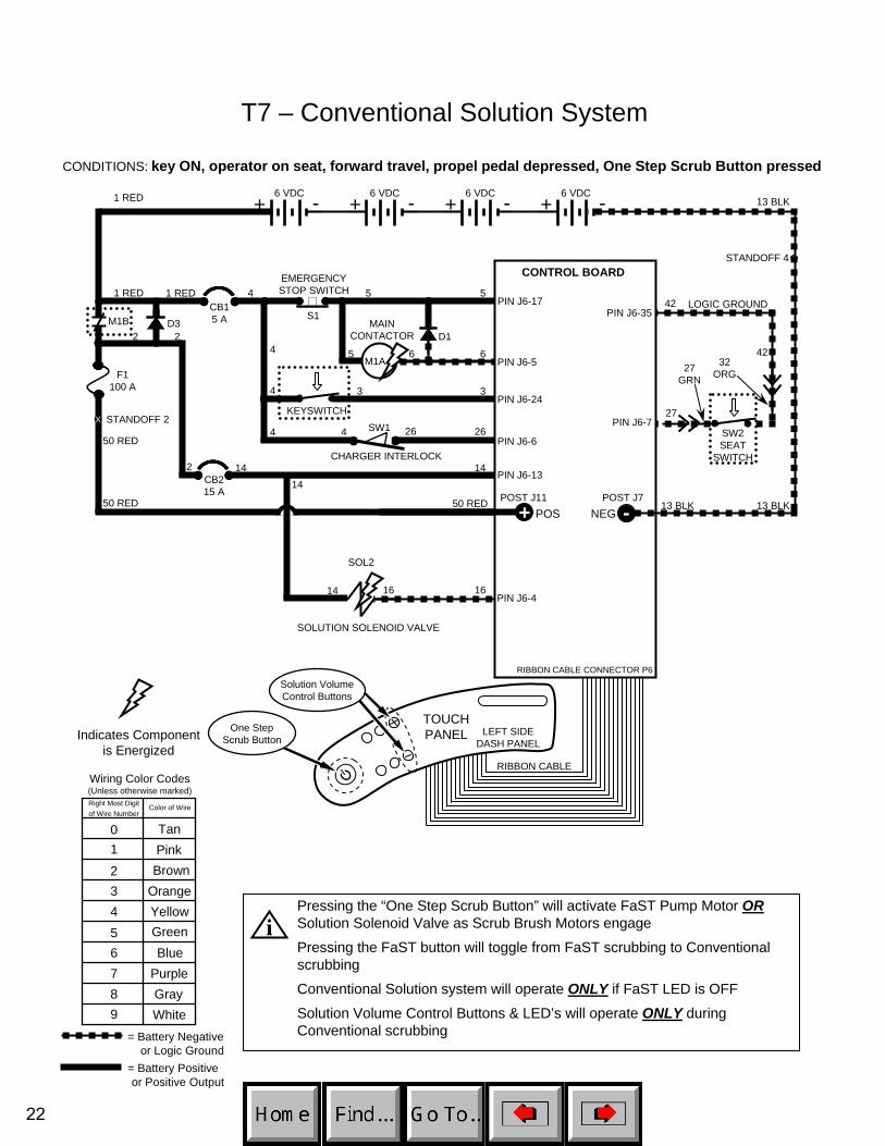
T7 – Conventional Solution System
CONDITIONS: key ON, operator on seat, forward travel, propel pedal depressed, One Step Scrub Button pressed
D3
1 RED 13 BLK
13 BLKPOS
CONTROL BOARD
STANDOFF 2
+ -6 VDC+ -6 VDC
+ -6 VDC+ -6 VDC
v v1 RED
STANDOFF 4
NEG50 RED
F1 100 A
S1
D1
CB15 A
CB2 15 A
KEYSWITCH
-
EMERGENCYSTOP SWITCH
X
50 RED
14
MAINCONTACTOR
6
55
5 6
3
26
3
4
4
4
4
PIN J6-17
PIN J6-5
PIN J6-24
PIN J6-6
PIN J6-1314
1 RED
50 RED
13 BLK
RIBBON CABLE CONNECTOR P6
POST J11 POST J7
CHARGER INTERLOCK
264 SW1
X
+
2 2
2
M1B
M1A
PIN J6-727
32ORG
42
4227
GRN
SW2SEAT
SWITCH
PIN J6-35LOGIC GROUND
TOUCH PANEL
RIBBON CABLE
LEFT SIDEDASH PANEL
One StepScrub Button
1614PIN J6-4
Indicates Componentis Energized
Wiring Color Codes(Unless otherwise marked)
01
23456789
TanPinkBrown
OrangeYellowGreenBlue
PurpleGrayWhite
Right Most Digitof Wire Number
Color of Wire
= Battery Negativeor Logic Ground
= Battery Positiveor Positive Output
14
SOLUTION SOLENOID VALVE
16
Solution VolumeControl Buttons
Pressing the “One Step Scrub Button” will activate FaST Pump Motor ORSolution Solenoid Valve as Scrub Brush Motors engage
Pressing the FaST button will toggle from FaST scrubbing to Conventional scrubbing
Conventional Solution system will operate ONLY if FaST LED is OFF
Solution Volume Control Buttons & LED’s will operate ONLY during Conventional scrubbing
i
SOL2
22
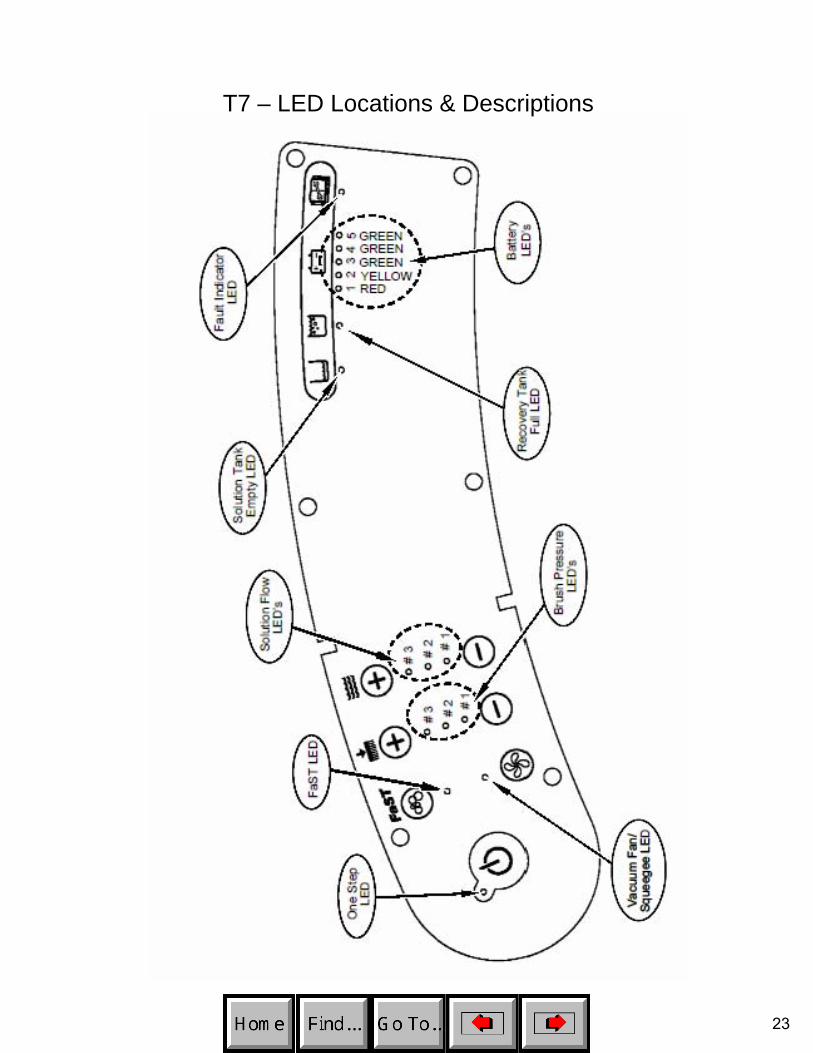
T7 – LED Locations & Descriptions
23
T7 – Operational Modes & Interlocks
Mode Entry Sequence Indicator Function
−Directional Switch Forward
−Propel Pedal Depressed
−Directional Switch Reverse −Directional Switch in Reverse position
−Propel Pedal Depressed −Horn Sounding continuously ON & OFF (except in "Hospital" mode)
Scrub Mode −Press One Step Scrub Button (ON) −One Step Scrub LED ON
Activate Scrub Brush, Squeegee, Vacuum Fan & Solution Flow operations
−Press One Step Scrub Button (ON) −One Step Scrub & FaST LED's ON
−Press FaST Button (ON) −Solution Flow LED's OFF
−Press One Step Scrub Button (ON) −One Step Scrub & Solution Flow LED(s) ON
−Press FaST Button (OFF) −FaST LED OFF
−Press One Step Scrub Button (ON) −One Step Scrub LED ON
−Press Vacuum Fan/Squeegee Button (OFF) −Vacuum Fan/Squeege LED OFF
−One Step Scrub LED OFF
−Vacuum Fan/Squeegee LED ON
−Lower Brush Pressure (#1) LED ON; Middle (#2) & Upper (#3) LED's OFF−Lower Solution Flow (#1) LED ON; Middle (#2) & Upper (#3) LED's OFF
−Press Brush Pressure Decrease (-) to one LED
−Lower Brush Pressure (#1) LED ON; Middle (#2) & Upper (#3) LED's OFF
−Press FaST Button (ON) −FaST LED ON (Solution Flow LED's OFF)
Recovery Tank Full
−Recovery Tank Full (Float Switch Closed) −Recovery Tank Full LED ON
Disable Scrub function (Operator can get an additional minute of operation by re-engaging scrub system with One Step button)
Battery Discharged
−Battery voltage at or below full discharge voltage −Red LED (on Battery Gauge) blinking
Disable Scrub function (Operator can get an additional minute of operation by re-engaging scrub system with One Step button)
−Fault LED ON and any one or more of the following:
Lower Brush Pressure (#1) LED ON (Right Motor) Upper Brush Pressure (#3) LED ON (Left Motor) Upper Solution Flow (#3) LED ON (Vacuum Fan)
Prevent damage to Scrub Brush Motors or Vacuum Fan Motor – Scrub function shuts off
Double Scrub (no water pickup)
Water pickup (no Scrub)
Accessory Motor High
Current Fault
−Controller sensed an Over Current condition in the Scrub Brush Motors or Vacuum Fan Motor
Forward
Reverse
FaST Mode
Conventional Solution Mode
−Press Brush Pressure Decrease (-) to one LED −Press Solution Flow Decrease (-) to one LED
−Solution Tank Empty LED ON
Disable Scrub function (Operator can get an additional minute of operation by re-engaging scrub system with One Step button)
Low Power Mode
Low Power Mode w/ FaST
Solution Tank Empty
Reduce Scrub Brush and Fan speeds (to prolong battery life, reduce noise, lower water usage)
Reduce Scrub Brush and Fan speeds (to prolong battery life, reduce noise, lower water usage)
−Solution Tank Empty (Float Switch Open)
Activate Conventional solution flow when scrub and propel are engaged
Apply cleaning solution with no water pickup
−Press Vacuum Fan/Squeegee Button (ON)
Collect solution on floor with squeegee, without scrubbing floor
−Directional Switch in Forward position Forward movement of machine
Reverse movement of machine
Activate FaST foam solution flow when scrub and propel are engaged
24

T7 – Diagnostic & Fault Alarms
Alarm CodesMode Directional
Switch Entry Sequence Alarm Sequence Function
Back-Up Alarm REVERSE Directional switch placed in REVERSE Horn sounds 1 beep cycle (repeats)
Alerts nearby persons of machine backward movement (Note: Back-
up alarm will not sound when machine is placed in "Hospital"
mode)
Propel Interlock: Seat Switch Released FORWARD
Propel Pedal depressed with operator NOT on
seatHorn sounds 2 beep cycle (repeats)
Prevents movement of machine when operator not in place
Propel interlock: High Pedal Disable FORWARD
Key switch turned ON with Propel
Pedal engagedHorn sounds 4 beep cycle (repeats)
Prevents movement of machine when key switched ON while throttle
depressed
Propel Interlock: Throttle Fault FORWARD
Controller sensed an out-of range Throttle signal
Horn sounds 5 beep cycle (repeats) (Also FAULT and FaST LED's blink)
Prevents movement of machine with invalid throttle voltage. Scrub
function shuts off.
Propel Interlock: Parking Brake Fault FORWARD
Controller sensed an out-of range
Brake signal
Horn sounds 6 beep cycle (repeats) (Also FAULT and Vacuum Fan/ Squeegee LED's blink)
Prevents movement of machine with invalid brake voltage. Scrub
function shuts off.
Propel Interlock: Parking Brake Unplugged FORWARD Controller sensed open
circuit on parking brakeHorn sounds 7 beep cycle (repeats) (Also FAULT and Lower Solution Flow LED's blink)
Prevents movement of machine with ineffective parking brake. Scrub
function shuts off.
Propel Interlock: E-STOP Switch Activated FORWARD
Controller sensed open circuit on Emergency
Stop Switch circuit
Horn sounds 8 beep cycle (repeats) (When in Input Display Mode, FAULT LED will also blink)
Disables all functions (Note: To reset, key switch must be
cycled OFF and ON after the E-STOP switch has closed)
Propel Interlock: Charger Plugged In FORWARD
Battery charger plugged into machine with Key Switch ON
Horn sounds 9 beep cycle (repeats)Prevents movement of the machine
with charger plugged in
High Current FaultsFault Entry Sequence Indicator
Excessive Left Brush Motor Current
Left brush motor current higher than 30 Amps Blinking FAULT LED, Blinking Brush Pressure LED #3
Excessive Right Brush Motor Current
Right brush motor current higher than 30 Amps Blinking FAULT LED, Blinking Brush Pressure LED #1
Excessive Vacuum Fan Motor Current
Vacuum Fan Motor current higher than 27 Amps Blinking FAULT LED, Blinking Vacuum Fan/Squeegee LED
Excessive Propel Motor Current
Blinking FAULT LED, Propel disabled
Propel Motor Current Higher than 40 Amps for 15 min. OR Higher than 55 Amps for 6 min.
OR Higher than 68 Amps for 4 min.
25
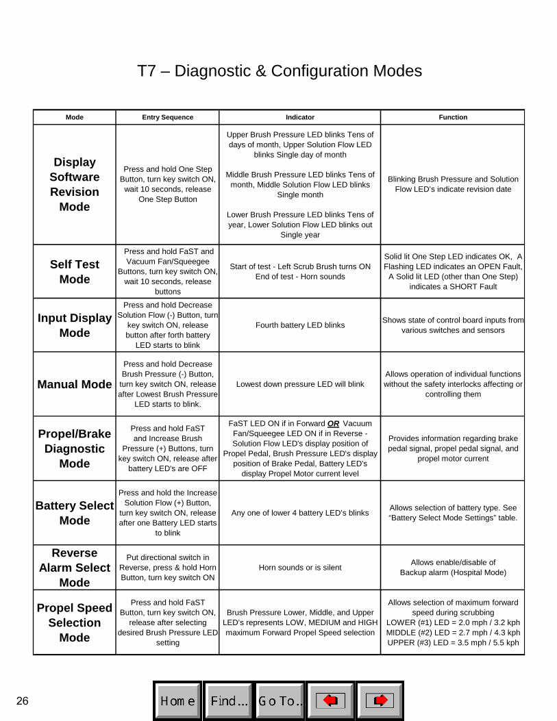
T7 – Diagnostic & Configuration Modes
Mode Entry Sequence Indicator Function
Upper Brush Pressure LED blinks Tens of days of month, Upper Solution Flow LED
blinks Single day of month
Middle Brush Pressure LED blinks Tens of month, Middle Solution Flow LED blinks
Single month
Lower Brush Pressure LED blinks Tens of year, Lower Solution Flow LED blinks out
Single year
Self Test Mode
Press and hold FaST and Vacuum Fan/Squeegee
Buttons, turn key switch ON, wait 10 seconds, release
buttons
Start of test - Left Scrub Brush turns ON End of test - Horn sounds
Solid lit One Step LED indicates OK, A Flashing LED indicates an OPEN Fault,
A Solid lit LED (other than One Step) indicates a SHORT Fault
Input Display Mode
Press and hold Decrease Solution Flow (-) Button, turn
key switch ON, release button after forth battery
LED starts to blink
Fourth battery LED blinks Shows state of control board inputs from various switches and sensors
Manual Mode
Press and hold Decrease Brush Pressure (-) Button,
turn key switch ON, release after Lowest Brush Pressure
LED starts to blink.
Lowest down pressure LED will blinkAllows operation of individual functions without the safety interlocks affecting or
controlling them
Propel/Brake Diagnostic
Mode
Press and hold FaST and Increase Brush
Pressure (+) Buttons, turn key switch ON, release after
battery LED's are OFF
FaST LED ON if in Forward OR Vacuum Fan/Squeegee LED ON if in Reverse - Solution Flow LED's display position of
Propel Pedal, Brush Pressure LED's display position of Brake Pedal, Battery LED's
display Propel Motor current level
Provides information regarding brake pedal signal, propel pedal signal, and
propel motor current
Battery Select Mode
Press and hold the Increase Solution Flow (+) Button,
turn key switch ON, release after one Battery LED starts
to blink
Any one of lower 4 battery LED’s blinks Allows selection of battery type. See “Battery Select Mode Settings” table.
Reverse Alarm Select
Mode
Put directional switch in Reverse, press & hold Horn Button, turn key switch ON
Horn sounds or is silent Allows enable/disable of Backup alarm (Hospital Mode)
Propel Speed Selection
Mode
Press and hold FaST Button, turn key switch ON,
release after selecting desired Brush Pressure LED
setting
Brush Pressure Lower, Middle, and Upper LED’s represents LOW, MEDIUM and HIGH maximum Forward Propel Speed selection
Allows selection of maximum forward speed during scrubbing
LOWER (#1) LED = 2.0 mph / 3.2 kph MIDDLE (#2) LED = 2.7 mph / 4.3 kph UPPER (#3) LED = 3.5 mph / 5.5 kph
Display Software Revision
Mode
Press and hold One Step Button, turn key switch ON,
wait 10 seconds, release One Step Button
Blinking Brush Pressure and Solution Flow LED’s indicate revision date
26
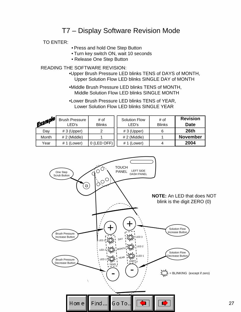
T7 – Display Software Revision ModeTO ENTER:
• Press and hold One Step Button• Turn key switch ON, wait 10 seconds• Release One Step Button
READING THE SOFTWARE REVISION:•Upper Brush Pressure LED blinks TENS of DAYS of MONTH,
Upper Solution Flow LED blinks SINGLE DAY of MONTH
•Middle Brush Pressure LED blinks TENS of MONTH, Middle Solution Flow LED blinks SINGLE MONTH
•Lower Brush Pressure LED blinks TENS of YEAR,Lower Solution Flow LED blinks SINGLE YEAR
Brush Pressure LED's
# of Blinks
Solution Flow LED's
# of Blinks
Revision Date
Day # 3 (Upper) 2 # 3 (Upper) 6 26thMonth # 2 (Middle) 1 # 2 (Middle) 1 NovemberYear # 1 (Lower) 0 (LED OFF) # 1 (Lower) 4 2004
TOUCH PANEL LEFT SIDE
DASH PANEL
+ +
- -
Brush PressureIncrease Button
Solution FlowIncrease Button
DAY
MONTH
YEAR
LED 3
LED 2
LED 1
LED 3
LED 2
LED 1
TENSONES
= BLINKING (except if zero)
One StepScrub Button
NOTE: An LED that does NOTblink is the digit ZERO (0)
Solution FlowDecrease Button
Brush PressureDecrease Button
27
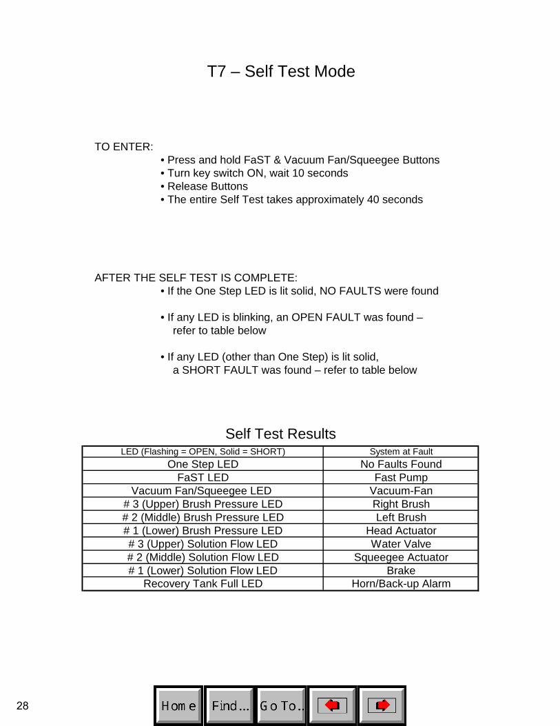
T7 – Self Test Mode
TO ENTER:• Press and hold FaST & Vacuum Fan/Squeegee Buttons• Turn key switch ON, wait 10 seconds• Release Buttons• The entire Self Test takes approximately 40 seconds
AFTER THE SELF TEST IS COMPLETE:• If the One Step LED is lit solid, NO FAULTS were found
• If any LED is blinking, an OPEN FAULT was found –refer to table below
• If any LED (other than One Step) is lit solid,a SHORT FAULT was found – refer to table below
Self Test ResultsLED (Flashing = OPEN, Solid = SHORT) System at Fault
One Step LED No Faults FoundFaST LED Fast Pump
Vacuum Fan/Squeegee LED Vacuum-Fan# 3 (Upper) Brush Pressure LED Right Brush# 2 (Middle) Brush Pressure LED Left Brush# 1 (Lower) Brush Pressure LED Head Actuator# 3 (Upper) Solution Flow LED Water Valve# 2 (Middle) Solution Flow LED Squeegee Actuator# 1 (Lower) Solution Flow LED Brake
Recovery Tank Full LED Horn/Back-up Alarm
28

T7 – Input Display Mode
INPU
TA
SSO
CIA
TED
LED
LED
IS O
N W
HEN
:LE
D IS
OFF
WH
EN:
NO
TES
Cha
rger
Inte
rlock
Sw
itch
FaS
T LE
DB
atte
ry c
harg
er IS
NO
T pl
ugge
d in
(s
witc
h is
CLO
SED
)Ba
ttery
cha
rger
IS p
lugg
ed in
(s
witc
h is
OP
EN)
FaS
T sy
stem
will
still
oper
ate,
but
with
out
indi
cato
r
Sea
t Sw
itch
# 5
(Gre
en) B
atte
ry L
ED
Ope
rato
r IS
NO
T si
tting
on
seat
(sw
itch
is O
PEN
)O
pera
tor I
S si
tting
on
Sea
t (sw
itch
is
CLO
SED
)
Rec
over
y Ta
nk F
loat
S
witc
hR
ecov
ery
Tank
Ful
l LED
Rec
over
y ta
nk IS
FU
LL (s
witc
h m
ust b
e C
LOSE
D fo
r 5 to
7 s
econ
ds a
fter O
ne
Ste
p B
utto
n is
act
ivat
ed)
Rec
over
y ta
nk IS
NO
T FU
LL (s
witc
h is
OP
EN)
Ope
ning
sw
itch
and
push
ing
the
the
One
Ste
p Bu
tton
turn
s LE
D o
ff ag
ain
Sol
utio
n Ta
nk F
loat
S
witc
hS
olut
ion
Tank
Em
pty
LED
Solu
tion
tank
IS E
MPT
Y (s
witc
h m
ust b
e O
PEN
for 5
to 7
sec
onds
afte
r One
Ste
p B
utto
n is
act
ivat
ed)
Solu
tion
tank
IS N
OT
EM
PTY
(sw
itch
is C
LOSE
D)
Clo
sing
sw
itch
and
push
ing
the
the
One
Ste
p B
utto
n tu
rns
LED
off
agai
n
Em
erge
ncy
Stop
Sw
itch
Faul
t Ind
icat
or L
ED
(Blin
king
)Em
erge
ncy
Sto
p S
witc
h IS
AC
TIVA
TED
(s
witc
h is
OPE
N)
Em
erge
ncy
Sto
p S
witc
h IS
NO
T AC
TIV
ATE
D (s
witc
h is
CLO
SED
)H
orn
will
repe
at 8
bee
p cy
cle
whe
n Em
erge
ncy
Sto
p S
witc
h is
act
ivat
ed
One
Ste
p Bu
tton
One
Ste
p LE
DSc
rub
syst
em IS
AC
TIV
ATE
DSc
rub
syst
em IS
NO
T A
CTI
VATE
D
Vac
uum
Fan
/Squ
eege
e B
utto
nV
acuu
m F
an/S
quee
gee
LED
Vac
uum
Fan
& S
quee
gee
ARE
AC
TIV
ATE
DVa
cuum
Fan
& S
quee
gee
AR
E N
OT
ACTI
VAT
ED
Bat
tery
Vol
tage
# 1
(Red
) Bat
tery
LED
Batte
ry n
eeds
cha
rgin
g (L
ED is
B
LIN
KIN
G)
Bat
tery
has
suf
ficie
nt c
harg
e le
vel
Left
Scr
ub B
rush
Lo
w P
ress
ure
# 1
(Low
er) B
rush
Pre
ssur
e LE
DLO
W s
crub
bru
sh c
urre
nt s
ense
dM
ediu
m P
ress
ure
# 2
(Mid
dle)
Bru
sh P
ress
ure
LED
ME
DIU
M s
crub
bru
sh c
urre
nt s
ense
dH
igh
Pre
ssur
e#
3 (U
pper
) Bru
sh P
ress
ure
LED
HIG
H s
crub
bru
sh c
urre
nt s
ense
d
Rig
ht S
crub
Bru
shLo
w P
ress
ure
# 1
(Low
er) S
olut
ion
Flow
LE
DLO
W s
crub
bru
sh c
urre
nt s
ense
dM
ediu
m P
ress
ure
# 2
(Mid
dle)
Sol
utio
n Fl
ow L
ED
ME
DIU
M s
crub
bru
sh c
urre
nt s
ense
dH
i gh
Pre
ss
TO E
NTE
R:
• Pre
ss a
nd h
old
the
Dec
reas
e S
olut
ion
Flow
(-) B
utto
n• T
urn
key
switc
h O
N•R
elea
se B
utto
n af
ter t
he #
4 B
atte
ry L
ED
blin
ks
The
purp
ose
of th
e In
put D
ispl
ay M
ode
is to
sho
w th
e co
nditi
on o
f var
ious
con
trol b
oard
inpu
ts
NO
TE: F
or P
rope
l & B
rake
sig
nal t
roub
lesh
ootin
g, re
fer t
o th
e P
rope
l Dia
gnos
tics
Mod
e pa
ge
ure
# 3
(Upp
er) S
olut
ion
Flow
LED
HIG
H s
crub
bru
sh c
urre
nt s
ense
d
Scru
b sy
stem
IS N
OT
AC
TIVA
TED
Scru
b sy
stem
IS N
OT
AC
TIVA
TED
29

T7 – Manual Mode
FUN
CTI
ON
BU
TTO
NA
CTI
ON
IND
ICA
TOR
NO
TES
Low
er S
crub
Hea
dO
ne S
tep
Pres
s &
Hol
dO
ne S
tep
LED
ON
Scru
b he
ad w
ill co
ntin
ue to
low
er a
s lo
ng a
s bu
tton
is h
eld
Ope
rate
Scr
ub B
rush
esO
ne S
tep
Rel
ease
but
ton
afte
r lo
wer
ing
scru
b he
adO
ne S
tep
LED
ON
Scru
b he
ad s
tops
low
erin
g af
ter O
ne S
tep
Butto
n is
rele
ased
Turn
OFF
Scr
ub B
rush
es
and
Rai
se S
crub
Hea
dO
ne S
tep
Pres
s &
Rel
ease
One
Ste
p LE
D O
FFSc
rub
head
rais
es to
to to
p of
stro
ke a
nd s
tops
Turn
ON
Vac
uum
Fan
an
d Lo
wer
Squ
eege
eV
acuu
m F
an/
Sque
egee
Pres
s &
Rel
ease
Vacu
um F
an/
Sq
ueeg
ee L
ED O
NIn
this
mod
e, p
ress
ing
the
One
Ste
p Bu
tton
durin
g lo
wer
ing
of
the
sque
egee
will
stop
squ
eege
e tra
vel
Turn
OFF
Vac
uum
Fan
an
d R
aise
Squ
eege
eV
acuu
m F
an/
Sque
egee
Pres
s &
Rel
ease
Vacu
um F
an/
Sq
ueeg
ee L
ED O
FFIn
this
mod
e, p
ress
ing
the
One
Ste
p Bu
tton
durin
g ra
isin
g of
th
e sq
ueeg
ee w
ill st
op s
quee
gee
trave
l
Turn
ON
FaS
T pu
mp
FaST
Pres
s &
Rel
ease
FaST
LED
ON
Turn
OFF
FaS
T pu
mp
FaST
Pre
ss &
Rel
ease
FaST
LED
OFF
Incr
ease
Sol
utio
n
Flow
Rat
eIn
crea
se S
olut
ion
Flow
(+)
Pres
s &
Rel
ease
Solu
tion
Flow
LED
'sIn
this
mod
e, th
e So
lutio
n Fl
ow a
utom
atic
ON
/OFF
inte
rlock
is d
isab
led
Dec
reas
e So
lutio
n
Flow
Rat
eD
ecre
ase
Solu
tion
Flow
(-)
Pres
s &
Rel
ease
Solu
tion
Flow
LED
'sIn
this
mod
e, th
e So
lutio
n Fl
ow a
utom
atic
ON
/OFF
inte
rlock
is d
isab
led
• Whe
n th
e So
lutio
n Em
pty
switc
h is
un-
grou
nded
for a
sho
rt tim
e, th
e So
lutio
n Em
pty
LED
will
light
• If t
he R
ecov
ery
Full
LED
or t
he S
olut
ion
Empt
y LE
D is
ON
, and
the
Scru
b Sy
stem
or V
acuu
m F
an/S
quee
gee
syst
em is
act
ivat
ed, t
he R
ecov
ery
Full
LED
and
So
lutio
n Em
pty
LED
will
turn
OFF
and
the
sens
ing
of b
oth
switc
hes
will
be d
isab
led
for a
bout
a m
inut
e
• For
saf
ety
cons
ider
atio
ns, t
he "H
igh
Peda
l Dis
able
" and
"Sea
t Sw
itch
Dis
able
" int
erlo
cks
& al
arm
s ar
e st
ill ac
tive
in M
anua
l Mod
e
• With
the
Dire
ctio
nal S
witc
h in
REV
ERSE
, the
Bac
k-up
Ala
rm w
ill so
und
but a
utom
atic
rais
ing
of th
e sq
ueeg
ee is
dis
able
d
ADD
ITIO
NAL
NO
TES
• Whe
n th
e R
ecov
ery
Full
switc
h is
gro
unde
d fo
r a s
hort
time,
the
Rec
over
y Fu
ll LE
D w
ill lig
ht
!C
AU
TIO
N: D
o no
t hol
d O
ne S
tep
Butto
n do
wn
too
long
- ac
tuat
or s
tall
will
occu
r, po
ssib
ly d
amag
ing
actu
ator
or c
ontro
l boa
rd
!C
AU
TIO
N: I
n th
is m
ode,
aut
omat
ic ra
isin
g of
the
sque
egee
whe
n in
REV
ER
SE is
dis
able
d
The
purp
ose
of th
e M
anua
l Mod
e is
to a
llow
func
tioni
ng o
f the
indi
vidu
al s
yste
ms
on th
e m
achi
ne w
ithou
t reg
ard
of m
ost s
afet
y in
terlo
cks
TO E
NTE
R:
• Pre
ss a
nd h
old
the
Dec
reas
e B
rush
Pre
ssur
e (-)
But
ton
• Tur
n ke
y sw
itch
ON
•Rel
ease
But
ton
afte
r # 1
(Low
er) B
rush
Pre
ssur
e LE
D b
links
30
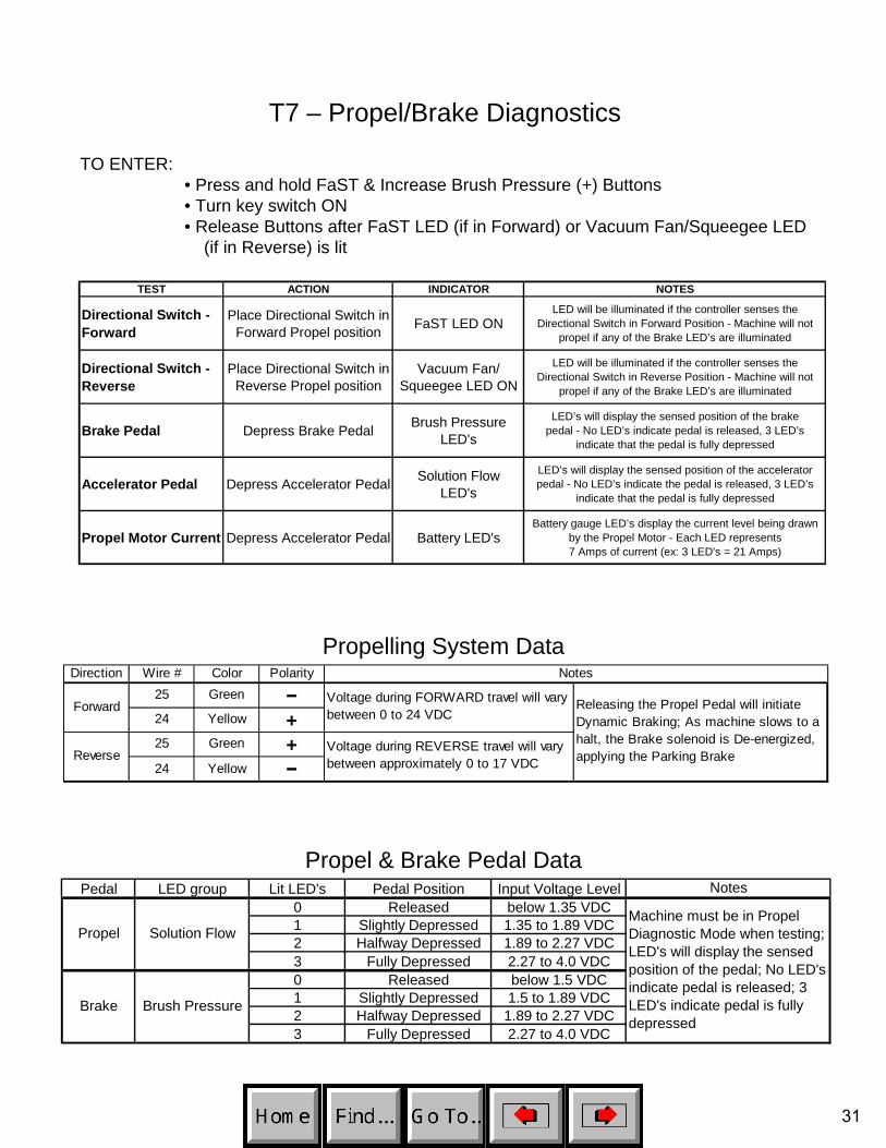
T7 – Propel/Brake Diagnostics
TO ENTER:• Press and hold FaST & Increase Brush Pressure (+) Buttons• Turn key switch ON• Release Buttons after FaST LED (if in Forward) or Vacuum Fan/Squeegee LED
(if in Reverse) is lit
TEST ACTION INDICATOR NOTES
Directional Switch - Forward
Place Directional Switch in Forward Propel position FaST LED ON
LED will be illuminated if the controller senses the Directional Switch in Forward Position - Machine will not
propel if any of the Brake LED’s are illuminated
Directional Switch - Reverse
Place Directional Switch in Reverse Propel position
Vacuum Fan/ Squeegee LED ON
LED will be illuminated if the controller senses the Directional Switch in Reverse Position - Machine will not
propel if any of the Brake LED’s are illuminated
Brake Pedal Depress Brake Pedal Brush Pressure LED's
LED’s will display the sensed position of the brake pedal - No LED’s indicate pedal is released, 3 LED’s
indicate that the pedal is fully depressed
Accelerator Pedal Depress Accelerator Pedal Solution Flow LED's
LED’s will display the sensed position of the accelerator pedal - No LED’s indicate the pedal is released, 3 LED’s
indicate that the pedal is fully depressed
Propel Motor Current Depress Accelerator Pedal Battery LED'sBattery gauge LED’s display the current level being drawn
by the Propel Motor - Each LED represents 7 Amps of current (ex: 3 LED's = 21 Amps)
Propelling System DataDirection Wire # Color Polarity
25 Green −24 Yellow "+"25 Green "+"24 Yellow −
Releasing the Propel Pedal will initiate Dynamic Braking; As machine slows to a halt, the Brake solenoid is De-energized, applying the Parking Brake
Notes
Forward
Reverse
Voltage during FORWARD travel will vary between 0 to 24 VDC
Voltage during REVERSE travel will vary between approximately 0 to 17 VDC
Propel & Brake Pedal DataPedal LED group Lit LED's Pedal Position Input Voltage Level Notes
0 Released below 1.35 VDC1 Slightly Depressed 1.35 to 1.89 VDC2 Halfway Depressed 1.89 to 2.27 VDC3 Fully Depressed 2.27 to 4.0 VDC0 Released below 1.5 VDC1 Slightly Depressed 1.5 to 1.89 VDC2 Halfway Depressed 1.89 to 2.27 VDC3 Fully Depressed 2.27 to 4.0 VDC
PropelMachine must be in Propel Diagnostic Mode when testing; LED's will display the sensed position of the pedal; No LED's indicate pedal is released; 3 LED's indicate pedal is fully depressed
Brake
Solution Flow
Brush Pressure
31
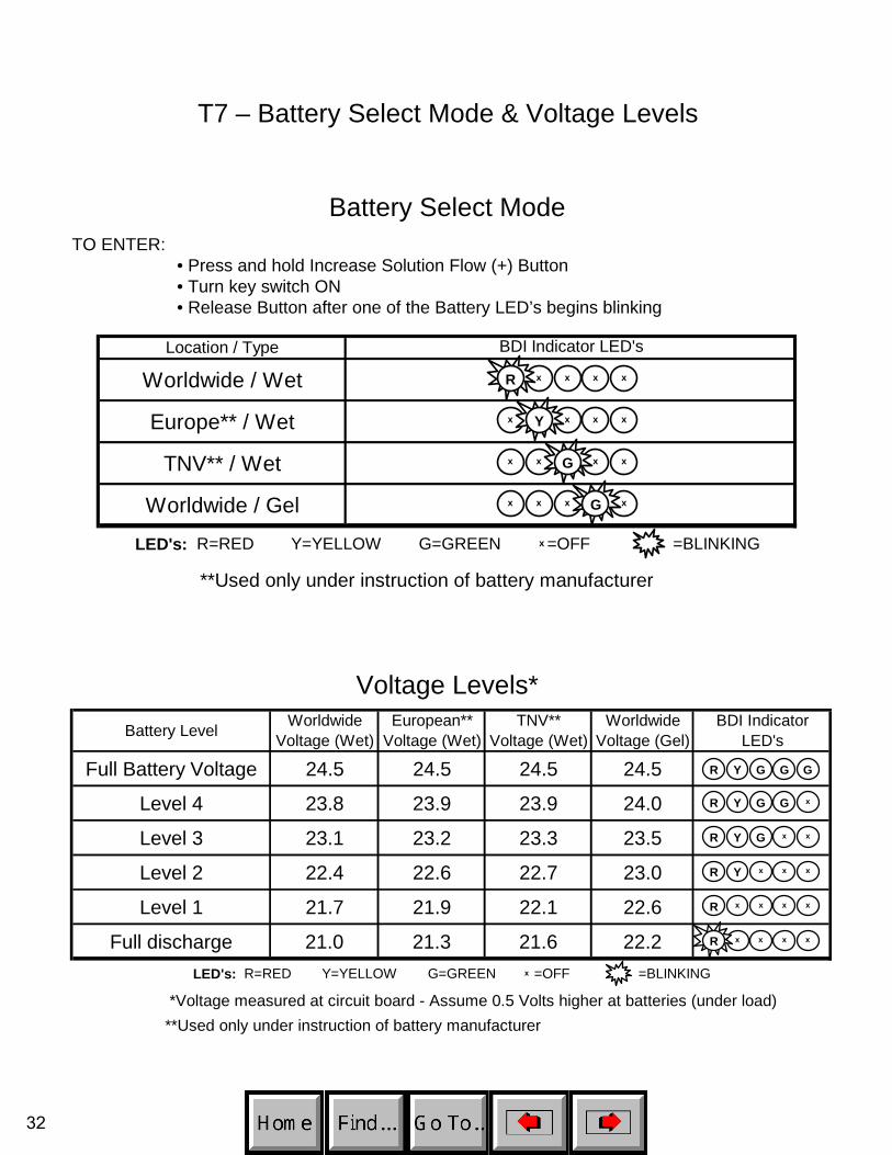
T7 – Battery Select Mode & Voltage Levels
Battery Select ModeTO ENTER:
• Press and hold Increase Solution Flow (+) Button• Turn key switch ON• Release Button after one of the Battery LED’s begins blinking
Location / Type
Worldwide / Wet
Europe** / Wet
TNV** / Wet
Worldwide / Gel
LED's: R=RED Y=YELLOW G=GREEN =OFF =BLINKING
BDI Indicator LED's
**Used only under instruction of battery manufacturer
x x
x x x x
x x x x
x x x x
x x
x
G
G
Y
R
Voltage Levels*Battery Level Worldwide
Voltage (Wet)European**
Voltage (Wet)TNV**
Voltage (Wet)Worldwide
Voltage (Gel)BDI Indicator
LED's
Full Battery Voltage 24.5 24.5 24.5 24.5
Level 4 23.8 23.9 23.9 24.0
Level 3 23.1 23.2 23.3 23.5
Level 2 22.4 22.6 22.7 23.0
Level 1 21.7 21.9 22.1 22.6
Full discharge 21.0 21.3 21.6 22.2
*Voltage measured at circuit board - Assume 0.5 Volts higher at batteries (under load)
LED's: R=RED Y=YELLOW G=GREEN =OFF =BLINKING
**Used only under instruction of battery manufacturer
x
R Y G G G
R Y G G x
R Y G x x
R Y x x x
R x x x x
R x x x
x
32
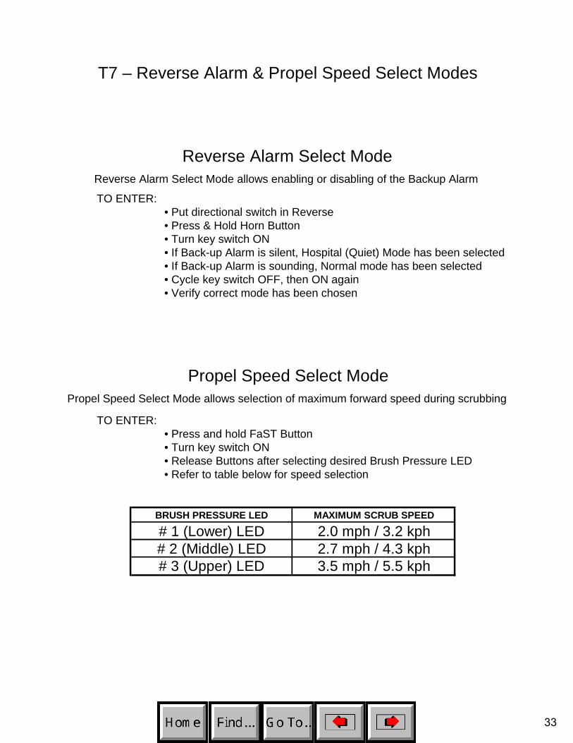
T7 – Reverse Alarm & Propel Speed Select Modes
Reverse Alarm Select ModeReverse Alarm Select Mode allows enabling or disabling of the Backup Alarm
TO ENTER:• Put directional switch in Reverse• Press & Hold Horn Button• Turn key switch ON• If Back-up Alarm is silent, Hospital (Quiet) Mode has been selected• If Back-up Alarm is sounding, Normal mode has been selected• Cycle key switch OFF, then ON again• Verify correct mode has been chosen
Propel Speed Select ModePropel Speed Select Mode allows selection of maximum forward speed during scrubbing
TO ENTER:• Press and hold FaST Button• Turn key switch ON• Release Buttons after selecting desired Brush Pressure LED• Refer to table below for speed selection
BRUSH PRESSURE LED MAXIMUM SCRUB SPEED
# 1 (Lower) LED 2.0 mph / 3.2 kph# 2 (Middle) LED 2.7 mph / 4.3 kph# 3 (Upper) LED 3.5 mph / 5.5 kph
33
Mai
n C
onta
ctor
ED
DP
rope
l For
war
dE
ED
DE
DE
DP
rope
l Rev
erse
EE
DD
DE*
*E
DD
ynam
ic B
raki
ng
Forc
e - I
ncre
ase
EE
DE
Park
ing
Bra
keE
ED
E***
Scr
ub M
otor
sE
DD
ED
DE
DS
crub
Hea
d P
ress
ure
Con
trol
ED
DE
DD
ED
Vac
uum
Mot
orE
DD
ED
DSq
ueeg
ee D
own
ED
DE
DD
ED
FaS
T S
yste
mE
DD
EE
DD
ED
Sol
utio
n So
leno
idE
DD
EH
our M
eter
O
pera
tion
EE*
Hor
nE
E**
E*
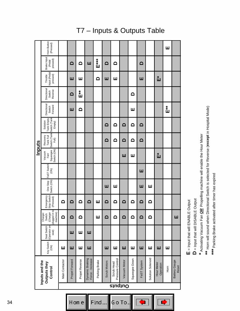
T7 – Inputs & Outputs Table
EBa
ttery
Gau
ge
Res
etE
E =
Inpu
t tha
t will
ENAB
LE O
utpu
t
D =
Inpu
t tha
t will
DIS
ABLE
Out
put
* Act
ivat
ing
Vacu
um F
an O
R P
rope
lling
mac
hine
will
enab
le th
e H
our M
eter
** H
orn
will
soun
d w
hen
Dire
ctio
nal S
witc
h is
sel
ecte
d fo
r Rev
erse
(exc
ept i
n H
ospi
tal M
ode)
*** P
arki
ng B
rake
act
ivat
ed a
fter t
imer
has
exp
ired
OutputsInpu
ts a
nd th
e
O
utpu
ts th
ey
C
ontr
olD
irect
iona
l S
witc
h R
ever
se
Dire
ctio
nal
Switc
h Fo
rwar
d
Thro
ttle
Inpu
t (Pe
dal
pres
sed)
Bra
ke In
put
(Ped
al
pres
sed)
Hor
n B
utto
n (P
ress
ed)
Inpu
tsC
harg
er
Sw
itch
(Cha
rger
pl
ugge
d in
to
mac
hine
)
Rec
over
y Ta
nk F
ull
Sw
itch
(Tan
kFu
ll)
Sol
utio
n Ta
nk E
mpt
y S
witc
h (T
ank
Em
pty)
Key
Sw
itch
(ON
)
Sea
t Sw
itch
(Ope
rato
r on
seat
)
Em
erge
ncy
Sto
p S
witc
h (P
ress
ed)
One
Ste
p Sw
itch
(ON
)Fa
ST
Sw
itch
(ON
)
Vacu
um
Fan/
Sq
ueeg
ee
Switc
h (O
N)
34
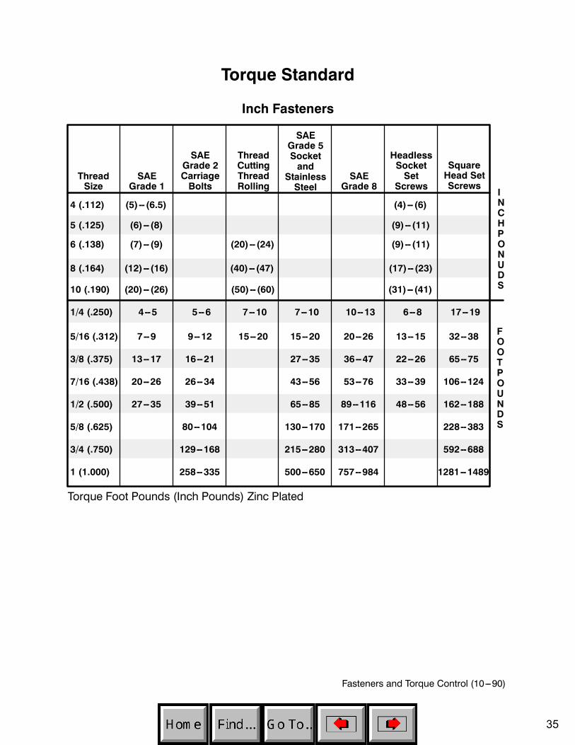
Fasteners and Torque Control (10---90)
Torque Standard
Inch Fasteners
(5)-- (6.5)
ThreadSize
SAEGrade 1
SAEGrade 2CarriageBolts
ThreadCuttingThreadRolling
SAEGrade 5Socketand
StainlessSteel
SAEGrade 8
HeadlessSocketSet
Screws
SquareHead SetScrews
4 (.112) (4)-- (6)
5 (.125) (6)-- (8) (9)-- (11)
6 (.138) (7)-- (9) (20)-- (24) (9)-- (11)
8 (.164) (12)-- (16) (40)-- (47) (17)-- (23)
10 (.190) (20)-- (26) (50)-- (60) (31)-- (41)
1/4 (.250) 4--5 5--6 7--10 7--10 10--13 6--8 17--19
5/16 (.312) 7--9 9--12 15--20 15--20 20--26 13--15 32--38
3/8 (.375) 13--17 16--21 27--35 36--47 22--26 65--75
7/16 (.438) 20--26 26--34 43--56 53--76 33--39 106--124
1/2 (.500) 27--35 39--51 65--85 89--116 48--56 162--188
5/8 (.625) 80--104 130--170 171--265 228--383
3/4 (.750) 129--168 215--280 313--407 592--688
1 (1.000) 258--335 500--650 757--984 1281--1489
INCHPONUDS
FOOTPOUNDS
Torque Foot Pounds (Inch Pounds) Zinc Plated
35

Fasteners and Torque Control (10---90)
Torque Standard
Inch Fasteners
FastenerIdentification Type Material
NominalSize
Proof Load(PSI)
TensileStrengthMin (PSI)
YieldStrengthMin (PSI)
Mechanical Properties
SAEGrade 1MachineScrews
Low orMediumCarbonSteel
#2 Thru#10
1/4 Thru1 1/2 33,000 36,000
55,000
60,000
SAEGrade 2CarriageBolts
Low orMediumCarbonSteel
1/4 Thru3/4
Over 3/4Thru 1 1/2
55,000
33,000
57,000 74,000
36,000 60,000
StainlessSteel
18--8AusteniticStainlessSteel
50,000 90,000
SAEGrade 5
MediumCarbonSteel
QuenchedTempered
1/4 Thru 1
Over 1 to1 1/2
85,000
74,000
92,000
81,000
120,000
105,000
SocketScrews
High CarbonAlloy SteelQuenchedTempered
136,000 160,000
SAEGrade 8
MediumCarbon Al-
loyQuenchedTempered
1/4 Thru1 1/2 120,000 130,000 150,000
36

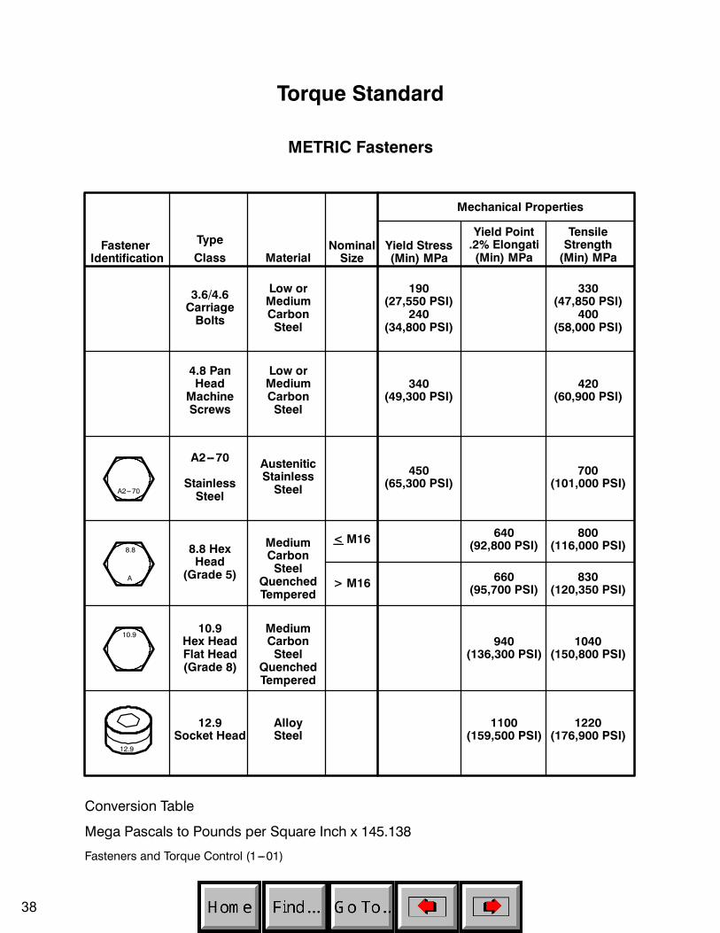
Fasteners and Torque Control (10---90)
Torque Standard
METRIC Fasteners
747--970 Ncm
18.3--23.7 Nm
ThreadSize 4.8/5.6
8.8StainlessSteel 10.9 12.9
SetScrews
M3 43--56 Ncm 99--128 Ncm 139--180 Ncm 166--215 Ncm 61--79 Ncm
M4 99--128 Ncm 223--290 Ncm 316--410 Ncm 381--495 Ncm 219--285 Ncm
M5 193--250 Ncm 443--575 Ncm 624--810 Ncm 427--554 Ncm
M6 3.3--4.3 Nm 7.6--9.9 Nm 10.8--14 Nm 12.7--16.5 Nm 7.5--9.8 Nm
M8 8.1--10.5 Nm 18.5--24 Nm 26.2--34 Nm 31--40 Nm
M10 16--21 Nm 37--48 Nm 52--67 Nm 63--81 Nm
M12 28--36 Nm 64--83 Nm 90--117 Nm 108--140 Nm
M14 45--58 Nm 102--132 Nm 142--185 Nm 169--220 Nm
M16 68--88 Nm 154--200 Nm 219--285 Nm 262--340 Nm
M20 132--171 Nm 300--390 Nm 424--550 Nm 508--660 Nm
NEWTON
CENTIMETERS
NEWTONMETERS
M22 177--230 Nm 409--530 Nm 574--745 Nm 686--890 Nm
M24 227--295 Nm 520--675 Nm 732--950 Nm 879--1140 Nm
Zinc Plated
Conversion Tables
Ncm to Inch Pound x 0.08851 Inch Pound to Ncm x 11.2982Nm to Foot Pound x 0.7376 Foot Pound to Nm x 1.3558
37
Fasteners and Torque Control (1---01)
Torque Standard
METRIC Fasteners
FastenerIdentification
Type
MaterialNominalSize
Yield Stress(Min) MPa
Yield Point.2% Elongati(Min) MPa
TensileStrength(Min) MPa
Mechanical Properties
3.6/4.6CarriageBolts
Low orMediumCarbonSteel
4.8 PanHead
MachineScrews
Low orMediumCarbonSteel
A2--70
StainlessSteel
AusteniticStainlessSteel
8.8 HexHead
(Grade 5)
MediumCarbonSteel
QuenchedTempered
10.9Hex HeadFlat Head(Grade 8)
12.9Socket Head
Class
190(27,550 PSI)
240(34,800 PSI)
330(47,850 PSI)
400(58,000 PSI)
340(49,300 PSI)
420(60,900 PSI)
450(65,300 PSI)
700(101,000 PSI)
< M16
> M16
640(92,800 PSI)
800(116,000 PSI)
660(95,700 PSI)
830(120,350 PSI)
MediumCarbonSteel
QuenchedTempered
940(136,300 PSI)
1040(150,800 PSI)
AlloySteel
A2---70
8.8
A
10.9
12.9
1100(159,500 PSI)
1220(176,900 PSI)
Conversion Table
Mega Pascals to Pounds per Square Inch x 145.138
38
Fasteners and Torque Control (10---90)
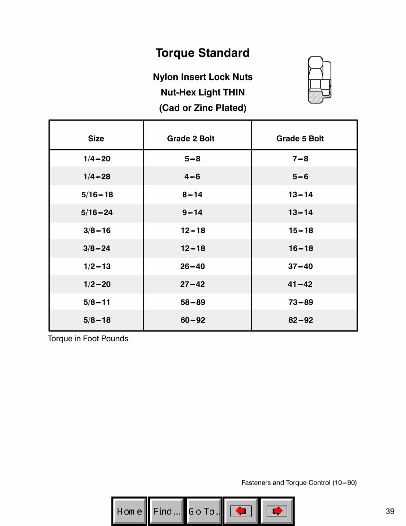
Size Grade 2 Bolt Grade 5 Bolt
1/4---20 5---8 7---8
1/4---28 4---6 5---6
5/16---18 8---14 13---14
5/16---24 9---14 13---14
3/8---16 12---18 15---18
3/8---24 12---18 16---18
1/2---13 26---40 37---40
1/2---20 27---42 41---42
5/8---11 58---89 73---89
5/8---18 60---92 82---92
Torque Standard
Nylon Insert Lock Nuts
Nut-Hex Light THIN
(Cad or Zinc Plated)
Torque in Foot Pounds
39
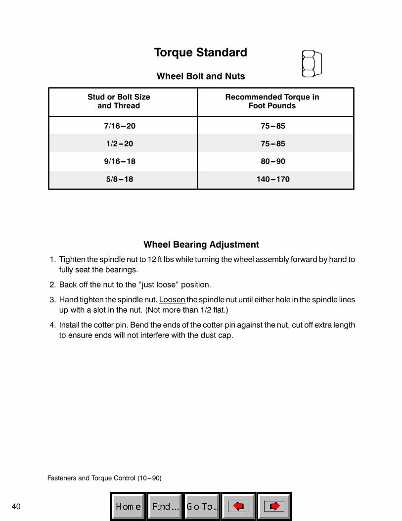
Fasteners and Torque Control (10---90)
Stud or Bolt Sizeand Thread
Recommended Torque inFoot Pounds
7/16---20 75---85
1/2---20 75---85
9/16---18 80---90
5/8---18 140---170
Torque Standard
Wheel Bolt and Nuts
Wheel Bearing Adjustment
1. Tighten the spindle nut to 12 ft lbs while turning the wheel assembly forward by hand tofully seat the bearings.
2. Back off the nut to the “just loose” position.
3. Hand tighten the spindle nut. Loosen the spindle nut until either hole in the spindle linesup with a slot in the nut. (Not more than 1/2 flat.)
4. Install the cotter pin. Bend the ends of the cotter pin against the nut, cut off extra lengthto ensure ends will not interfere with the dust cap.
40

Fasteners and Torque Control (10---90)
Tightening Nuts on Tapered Shafts
.37301”--20 UNEF--2B SLOTTEDHEX LOCKNUT PER SAEJ--501 (EXCEPT 1.50/38,1ACROSS FLATS).RECOMMENDED TOQUE TO175 FT LB PLUS TORQUEREQUIRED TO ALIGNSLOTTED NUT TO SHAFTHOLE
2.27/57,7CLEARANCE
DIA. PSHAFTDIA.
1.500 + .002 TAPER PERFOOT/125 + 0,17 MM TAPERPER METER
.750 + .01019,05 + 0,25
1.89048,01
+.0010-- .00000 /9,474
+0,025--0
3.0076,2
KEY WIDTH
.1563,96 DIA. THRU
Example ofrecommendedtorque.
Check with the manufacturer to see what the recommended maximum torque is.Tighten the slotted nut to a lower torque, and then tighten the nut to align the cotter pinhole with the slot on the nut. Do not exceed the recommended torque. Do not back offthe nut to align the holes.Motor Tapered Shaft Nut Info. Torque Specification Recommendations
A&H Series 1.00 dia. .75--16 UNF 150 ft lb dry1.107 Hex 125 ft lb lubricated
Plus torque to align for pin
2000 Series 1.25 dia. 1--20 UNEF 225 ft lb dry1.44 Hex 225 ft lb lubricated
PLUS torque to align for pin
4000 Series 1.625 dia. 1.25--18 UNEF 475 ft lb dry2.187 Hex 375 ft lb lubricated
PLUS torque to align for pin
6000 Series 1.75 dia. 1.25--18 UNEF 475 ft lb dry2.187 Hex 375 ft lb lubricated
PLUS torque to align for pin
41
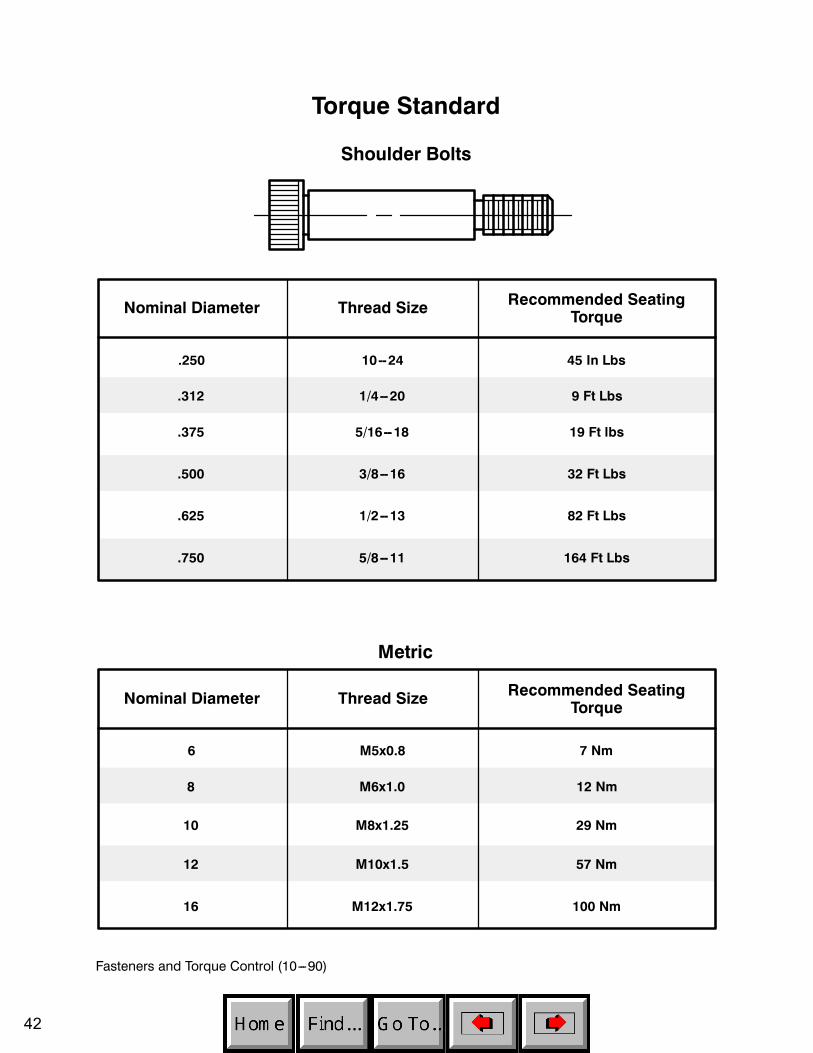
Fasteners and Torque Control (10---90)
Nominal Diameter
Torque Standard
Shoulder Bolts
Thread Size Recommended SeatingTorque
.250 10--24
.312
45 In Lbs
1/4--20 9 Ft Lbs
.375 5/16--18 19 Ft lbs
.500 3/8--16 32 Ft Lbs
.625 1/2--13 82 Ft Lbs
.750 5/8--11 164 Ft Lbs
Nominal Diameter Thread Size Recommended SeatingTorque
6
8
7 Nm
M6x1.0 12 Nm
10 M8x1.25 29 Nm
12 M10x1.5 57 Nm
16 M12x1.75 100 Nm
M5x0.8
Metric
42

Fasteners and Torque Control (10---90)
Taper Lockr BushingsIMPORTANT: Follow all these instructions carefully. This is necessary to insuresatisfactory performance.
C C
1008 to 3030
To Install1. Clean shaft, bore and outside of bushing, and hub bore of all oil, lacquer, and dirt.
2. Insert bushing in hub. Match the hole pattern, not threaded holes (each hole will bethreaded on one side only).
3. Oil setscrews and thread into those half threaded holes indicated by C on abovediagram.
4. Alternately torque setscrews to recommended torque setting in chart below.
5. Using a block, sleeve, or drift, hammer large end of bushing (do not hammer bushingdirectly).
6. Repeat steps 4 and 5 until torque wrench reading after hammering is the same asbefore hammering.
7. Fill all unoccupied holes with grease.
To Remove1. Remove all setscrews.
2. Insert setscrews in holes indicated byD on the diagram. Loosenbushing by alternatelytightening setscrews.
3. To reinstall, complete all seven (7) steps installation steps.Recommended Wrench Torque
Bushing No. ScrewsWrench Torque(Pound-Inch)
HammerSize
1008, 11081210, 1215, 1310
1610, 1615
1/4” Setscrews3/8” Setscrews3/8” Setscrews
55175175
6 lb6 lb6 lb
20122517, 25253020, 3030
7/16” Setscrews1/2” Setscrews5/8” Setscrews
280430800
6 lb6 lb6 lb
If two bushings are used on same component and shaft, fully tighten one bushing beforeworking on the other.
43
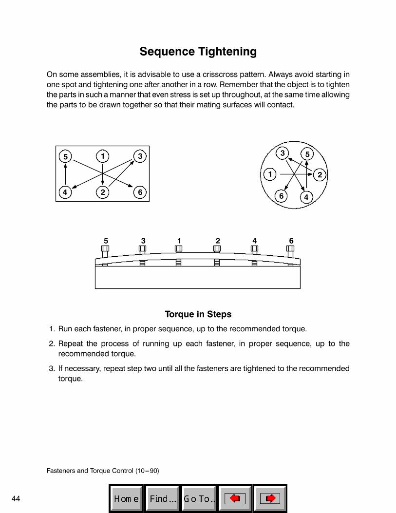
Fasteners and Torque Control (10---90)
Sequence Tightening
On some assemblies, it is advisable to use a crisscross pattern. Always avoid starting inone spot and tightening one after another in a row. Remember that the object is to tightenthe parts in such amanner that even stress is set up throughout, at the same time allowingthe parts to be drawn together so that their mating surfaces will contact.
5 1 3
4 2 6
1 2
53
6 4
1 23 45 6
Torque in Steps
1. Run each fastener, in proper sequence, up to the recommended torque.
2. Repeat the process of running up each fastener, in proper sequence, up to therecommended torque.
3. If necessary, repeat step two until all the fasteners are tightened to the recommendedtorque.
44