Embed Size (px)
Citation preview
Z-Power LED X10490
Technical Data Sheet
Rev. 07 Rev. 07
May. 2009May. 2009
www.ZLED.com www.ZLED.com 1
Document No. : SSC-QP-7-07-24 (Rev.00)
X42180 X42180
Features• Super high flux output
and high luminance
• Designed for high
current operation
• Low thermal resistance
• SMT solderability
• Lead free product
• RoHS compliant
Applications• Mobile phone flash
• Automotive interior / Exterior lighting
• Automotive signal lighting
• Automotive forward lighting
• Torch
• Architectural lighting
• LCD TV / Monitor backlight
• Projector light source
• Traffic signals
• Task lighting
• Decorative / Pathway lighting
• Remote / Solar powered lighting
• Household appliances
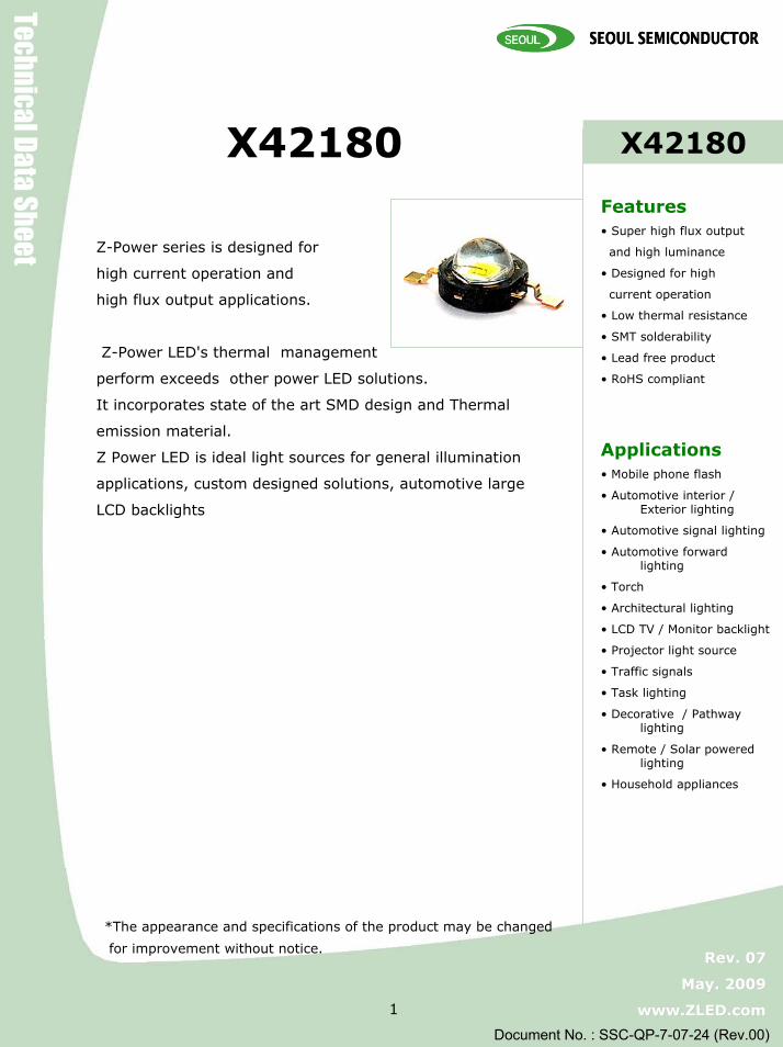
사진Z-Power series is designed for
high current operation and
high flux output applications.
Z-Power LED's thermal management
perform exceeds other power LED solutions.
It incorporates state of the art SMD design and Thermal
emission material.
Z Power LED is ideal light sources for general illumination
applications, custom designed solutions, automotive large
LCD backlights
*The appearance and specifications of the product may be changed
for improvement without notice.
Z-Power LED X10490
Z-Power LED X10490
Technical Data Sheet
Rev. 07 Rev. 07
May. 2009 May. 2009
www.ZLED.com www.ZLED.com 2
Document No. : SSC-QP-7-07-24 (Rev.00)
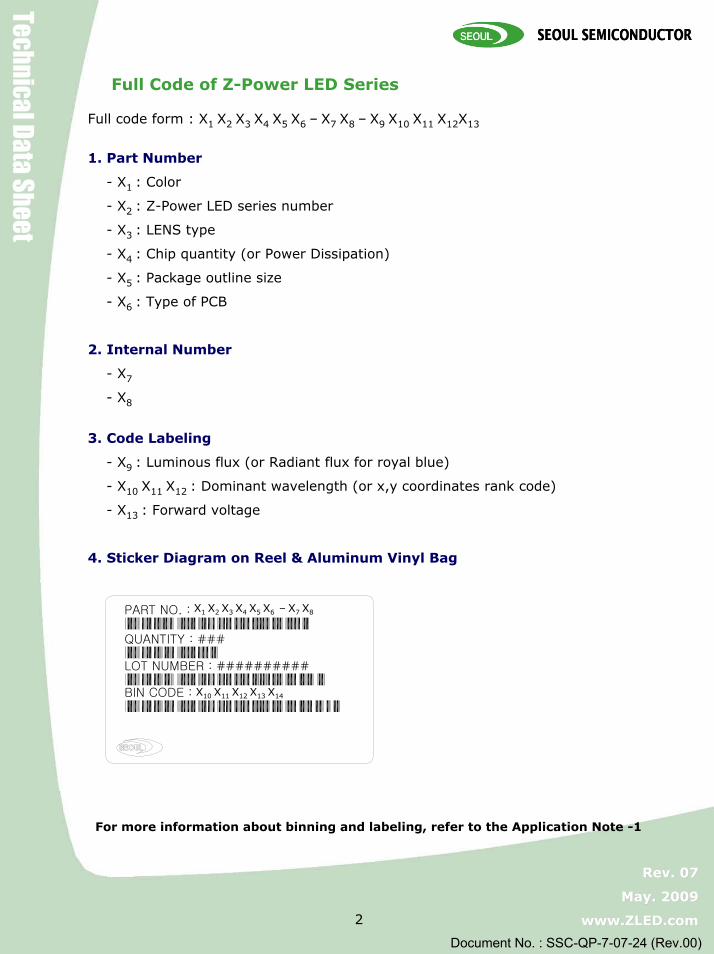
Full Code of Z-Power LED Series
Full code form : X1 X2 X3 X4 X5 X6 – X7 X8 – X9 X10 X11 X12X13
1. Part Number
- X1 : Color
- X2 : Z-Power LED series number
- X3 : LENS type
- X4 : Chip quantity (or Power Dissipation)
- X5 : Package outline size
- X6 : Type of PCB
2. Internal Number
- X7
- X8
3. Code Labeling
- X9 : Luminous flux (or Radiant flux for royal blue)
- X10 X11 X12 : Dominant wavelength (or x,y coordinates rank code)
- X13 : Forward voltage
4. Sticker Diagram on Reel & Aluminum Vinyl Bag
For more information about binning and labeling, refer to the Application Note -1
PART NO. :
QUANTITY : ###
LOT NUMBER : ##########
BIN CODE :
X1 X2 X3 X4 X5 X6 – X7 X8
X10 X11 X12 X13 X14

Z-Power LED X10490
Z-Power LED X10490
Technical Data Sheet
Rev. 07 Rev. 07
May. 2009 May. 2009
www.ZLED.com www.ZLED.com 3
Document No. : SSC-QP-7-07-24 (Rev.00)
1. Dome Type
Notes :
1. All dimensions are in millimeters. (tolerance : ±0.2 )2. Scale : none3. Slug of package is connected to anode.
*The appearance and specifications of the product may be changed for improvement without notice.
Body
Lead
Cathode Mark
Lens
SLUG
Outline Dimension

Z-Power LED X10490
Z-Power LED X10490
Technical Data Sheet
Rev. 07 Rev. 07
May. 2009 May. 2009
www.ZLED.com www.ZLED.com 4
Document No. : SSC-QP-7-07-24 (Rev.00)
1. Pure White (W42180)1-1 Electro-Optical characteristics at IF=350mA, TA=25ºC
1-2 Absolute Maximum Ratings
Thermal resistance [6]
Thermal resistance [5]
View Angle
Forward Voltage [4]
CRI
Correlated Color Temperature [3]
Luminous Flux [1]
Parameter
lm918070ФV [2]T rank
ºC /W8.8RθJ-B
ºC /W7.2RθJ-C
V43.252.9VF
K-6300-CCT
MaxTypMin
-
-
75
100
deg.1272Θ ½
--Ra
lm91ФV [2]U rank
UnitValue
Symbol
mA1000 (@ Tj = 90 ºC) [7]
IFForward Current1800 (@ 1KHz, 1/10 duty)
W4PdPower Dissipation
ºC145(@ IF ≤ 700mA)TjJunction Temperature
-±10,000V HBM-ESD Sensitivity [8]
ºC-40 ~ +100TstgStorage Temperature
ºC-40 ~ +85ToprOperating Temperature
UnitValueSymbolParameter
*Notes : [1] SSC maintains a tolerance of ±10% on flux and power measurements.[2] ФV is the total luminous flux output as measured with an integrated sphere.[3] Correlated Color Temperature is derived from the CIE 1931 Chromaticity diagram. CCT ±5%
tester tolerance.[4] A tolerance of ±0.06V on forward voltage measurements[5], [6] RθJ-B is measured with a SSC metal core pcb.(25 ºC ≤TJ ≤ 110 ºC)
RθJ-C is measured with only emitter. (25 ºC ≤TJ ≤ 110 ºC)Break voltage of Metal PCB is 6.5kVAC.
[7] IF Max is guaranteed under the TJ ≤90 ºC.[8] It is included the zener chip to protect the product from ESD.
--------------------------Caution--------------------------1. Please do not drive at rated current more than 5 sec. without proper heat sink.
Characteristics for Z-Power LED

Z-Power LED X10490
Z-Power LED X10490
Technical Data Sheet
Rev. 07 Rev. 07
May. 2009 May. 2009
www.ZLED.com www.ZLED.com 5
Document No. : SSC-QP-7-07-24 (Rev.00)
2. Warm White (N42180)2-1 Electro-Optical characteristics at IF=350mA, TA=25ºC
2-2 Absolute Maximum Ratings
ºC /W8.5RθJ-BThermal resistance [5]
ºC /W6.9RθJ-CThermal resistance [6]
V43.252.9VFForward Voltage [4]
K-3000-CCTCorrelated Color Temperature [3]
MaxTypMin
-
-
93
53
deg.1242Θ 1/2View Angle
--RaCRI
lm-ФV [2]Luminous Flux [1]
UnitValue
SymbolParameter
*Notes : [1] SSC maintains a tolerance of ±10% on flux and power measurements.[2] ФV is the total luminous flux output as measured with an integrated sphere.[3] Correlated Color Temperature is derived from the CIE 1931 Chromaticity diagram.
CCT ±5% tester tolerance[4] A tolerance of ±0.06V on forward voltage measurements[5], [6] RθJ-B is measured with a SSC metal core pcb.(25 ºC ≤TJ ≤ 110 ºC)
RθJ-C is measured with only emitter. .(25 ºC ≤TJ ≤ 110 ºC)Break voltage of Metal PCB is 6.5kVAC
[7] It is included the zener chip to protect the product from ESD.
--------------------------Caution--------------------------1. Please do not drive at rated current more than 5 sec. without proper heat sink
mA800IFForward Current
W3.2PdPower Dissipation
ºC145TjJunction Temperature
-±10,000V HBM-ESD Sensitivity [7]
ºC-40 ~ +100TstgStorage Temperature
ºC-40 ~ +85ToprOperating Temperature
UnitValueSymbolParameter
Characteristics for Z-Power LED

Z-Power LED X10490
Z-Power LED X10490
Technical Data Sheet
Rev. 07 Rev. 07
May. 2009 May. 2009
www.ZLED.com www.ZLED.com 6
Document No. : SSC-QP-7-07-24 (Rev.00)
3. Natural White (S42180)3-1 Electro-Optical characteristics at IF=350mA, TA=25ºC
3-2 Absolute Maximum Ratings
ºC /W8.5RθJ-BThermal resistance [5]
ºC /W6.9RθJ-CThermal resistance [6]
V43.252.9VFForward Voltage [4]
K-4000-CCTCorrelated Color Temperature [3]
MaxTypMin
-
-
93
61
deg.1242Θ 1/2View Angle
--RaCRI
lm-ФV [2]Luminous Flux [1]
UnitValue
SymbolParameter
--------------------------Caution--------------------------1. Please do not drive at rated current more than 5 sec. without proper heat sink
mA800IFForward Current
W3.2PdPower Dissipation
ºC145TjJunction Temperature
-±10,000V HBM-ESD Sensitivity [8]
ºC-40 ~ +100TstgStorage Temperature
ºC-40 ~ +85ToprOperating Temperature
UnitValueSymbolParameter
*Notes : [1] SSC maintains a tolerance of ±10% on flux and power measurements.[2] ФV is the total luminous flux output as measured with an integrated sphere.[3] Correlated Color Temperature is derived from the CIE 1931 Chromaticity diagram. CCT ±5%
tester tolerance.[4] A tolerance of ±0.06V on forward voltage measurements[5], [6] RθJ-B is measured with a SSC metal core pcb.(25 ºC ≤TJ ≤ 110 ºC)
RθJ-C is measured with only emitter. (25 ºC ≤TJ ≤ 110 ºC)Break voltage of Metal PCB is 6.5kVAC.
[7] It is included the zener chip to protect the product from ESD.
Characteristics for Z-Power LED

Z-Power LED X10490
Z-Power LED X10490
Technical Data Sheet
Rev. 07 Rev. 07
May. 2009 May. 2009
www.ZLED.com www.ZLED.com 7
Document No. : SSC-QP-7-07-24 (Rev.00)
4. Blue (B42180)4-1 Electro-Optical characteristics at IF=350mA, TA=25ºC
4-2 Absolute Maximum Ratings
deg.1302Θ 1/2View Angle
ºC /W8.5RθJ-BThermal resistance [5]
ºC /W6.9RθJ-CThermal resistance [6]
V43.252.9VFForward Voltage [4]
nm475465455λDDominant Wavelength[3]
MaxTypMin
-22 lm-ФV [2]Luminous Flux [1]
UnitValue
SymbolParameter
W4PdPower Dissipation
ºC145TjJunction Temperature
mA1000IFForward Current
-±10,000V HBM-ESD Sensitivity [7]
ºC-40 ~ +100TstgStorage Temperature
ºC-40 ~ +85ToprOperating Temperature
UnitValueSymbolParameter
*Notes : [1] SSC maintains a tolerance of ±10% on flux and power measurements.[2] ФV is the total luminous flux output as measured with an integrated sphere.[3] Dominant wavelength is derived from the CIE 1931 Chromaticity diagram.
A tolerance of ±0.5nm for dominant wavelength[4] A tolerance of ±0.06V on forward voltage measurements[5], [6] RθJ-B is measured with a SSC metal core pcb.(25 ºC ≤TJ ≤ 110 ºC)
RθJ-C is measured with only emitter. .(25 ºC ≤TJ ≤ 110 ºC)Break voltage of Metal PCB is 6.5kVAC
[7] It is included the zener chip to protect the product from ESD.
--------------------------Caution--------------------------1. Please do not drive at rated current more than 5 sec. without proper heat sink2. Blue power light sources represented here are IEC825 Class 2 for eye safety
Characteristics for Z-Power LED

Z-Power LED X10490
Z-Power LED X10490
Technical Data Sheet
Rev. 07 Rev. 07
May. 2009 May. 2009
www.ZLED.com www.ZLED.com 8
Document No. : SSC-QP-7-07-24 (Rev.00)
5. Royal Blue (D42180)5-1 Electro-Optical characteristics at IF=350mA, TA=25ºC
5-2 Absolute Maximum Ratings
*Notes : [1] SSC maintains a tolerance of ±10% on flux and power measurements.[2] ФV is the total luminous flux output as measured with an integrated sphere.[3] Correlated Color Temperature is derived from the CIE 1931 Chromaticity diagram.
CCT ±5% tester tolerance[4] A tolerance of ±0.06V on forward voltage measurements[5], [6] RθJ-B is measured with a SSC metal core pcb.(25 ºC ≤TJ ≤ 110 ºC)
RθJ-C is measured with only emitter. .(25 ºC ≤TJ ≤ 110 ºC)Break voltage of Metal PCB is 6.5kVAC
[7] It is included the zener chip to protect the product from ESD.
--------------------------Caution--------------------------1. Please do not drive at rated current more than 5 sec. without proper heat sink2. Blue power light sources represented here are IEC825 Class 2 for eye safety
Characteristics for Z-Power LED
deg.1302Θ 1/2View Angle
ºC /W8.5RθJ-BThermal resistance [5]
nm460457455λDDominant Wavelength [3]
MaxTypMin
3.8
-
3.25
468
ºC /W6.9RθJ-CThermal resistance [6]
V2.9VFForward Voltage [4]
mW-ФV [2]Radiant Power [1]
UnitValue
SymbolParameter
W4PdPower Dissipation
ºC145TjJunction Temperature
mA1000IFForward Current
-±10,000V HBM-ESD Sensitivity [7]
ºC-40 ~ +100TstgStorage Temperature
ºC-40 ~ +85ToprOperating Temperature
UnitValueSymbolParameter

Z-Power LED X10490
Z-Power LED X10490
Technical Data Sheet
Rev. 07 Rev. 07
May. 2009 May. 2009
www.ZLED.com www.ZLED.com 9
Document No. : SSC-QP-7-07-24 (Rev.00)
6. Green (G42180)6-1 Electro-Optical characteristics at IF=350mA, TA=25ºC
6-2 Absolute Maximum Ratings
deg.1302Θ 1/2View Angle
ºC /W9.5RθJ-BThermal resistance [5]
ºC /W8.0RθJ-CThermal resistance [6]
V43.252.9VFForward Voltage [4]
nm535525520λDDominant Wavelength[3]
MaxTypMin
-70 lm-ФV [2]Luminous Flux [1]
UnitValue
SymbolParameter
W4PdPower Dissipation
ºC145TjJunction Temperature
mA1000IFForward Current
-±10,000V HBM-ESD Sensitivity [7]
ºC-40 ~ +100TstgStorage Temperature
ºC-40 ~ +85ToprOperating Temperature
UnitValueSymbolParameter
*Notes : [1] SSC maintains a tolerance of ±10% on flux and power measurements.[2] ФV is the total luminous flux output as measured with an integrated sphere.[3] Dominant wavelength is derived from the CIE 1931 Chromaticity diagram.
A tolerance of ±0.5nm for dominant wavelength[4] A tolerance of ±0.06V on forward voltage measurements[5], [6] RθJ-B is measured with a SSC metal core pcb.(25 ºC ≤TJ ≤ 110 ºC)
RθJ-C is measured with only emitter. .(25 ºC ≤TJ ≤ 110 ºC)Break voltage of Metal PCB is 6.5kVAC
[7] It is included the zener chip to protect the product from ESD.
--------------------------Caution--------------------------1. Please do not drive at rated current more than 5 sec. without proper heat sin
Characteristics for Z-Power LED

Z-Power LED X10490
Z-Power LED X10490
Technical Data Sheet
Rev. 07 Rev. 07
May. 2009 May. 2009
www.ZLED.com www.ZLED.com 10
Document No. : SSC-QP-7-07-24 (Rev.00)
Characteristics for Z-Power LED
7. Red (R42180)7-1 Electro-Optical characteristics at IF=350mA, TA=25ºC
7-2 Absolute Maximum Ratings
ote1] SSC maintains a tolerance
ºC /W9RθJ-BThermal resistance [5]
deg.1302Θ 1/2View Angle
V3.02.32.0VFForward Voltage [4]
nm630625618λDDominant Wavelength[3]
MaxTypMin
-48
ºC /W7.8RθJ-CThermal resistance [6]
lm-ФV [2]Luminous Flux [1]
UnitValue
SymbolParameter
W2.4PdPower Dissipation
ºC145TjJunction Temperature
mA800IFForward Current
-±10,000V HBM-ESD Sensitivity [7]
ºC-40 ~ +100TstgStorage Temperature
ºC-40 ~ +85ToprOperating Temperature
UnitValueSymbolParameter
*N s : [ of ±10% on flux and power measurements.[2] ФV is the total luminous flux output as measured with an integrated sphere.[3] Dominant wavelength is derived from the CIE 1931 Chromaticity diagram.
A tolerance of ±0.5nm for dominant wavelength[4] A tolerance of ±0.06V on forward voltage measurements[5], [6] RθJ-B is measured with a SSC metal core pcb.(25 ºC ≤TJ ≤ 110 ºC)
RθJ-C is measured with only emitter. .(25 ºC ≤TJ ≤ 110 ºC)Break voltage of Metal PCB is 6.5kVAC
[7] It is included the zener chip to protect the product from ESD.
--------------------------Caution--------------------------1. Please do not drive at rated current more than 5 sec. without proper heat sink
Z-Power LED X10490
Z-Power LED X10490
Technical Data Sheet
Rev. 07 Rev. 07
May. 2009 May. 2009
www.ZLED.com www.ZLED.com 11
Document No. : SSC-QP-7-07-24 (Rev.00)
Characteristics for Z-Power LED
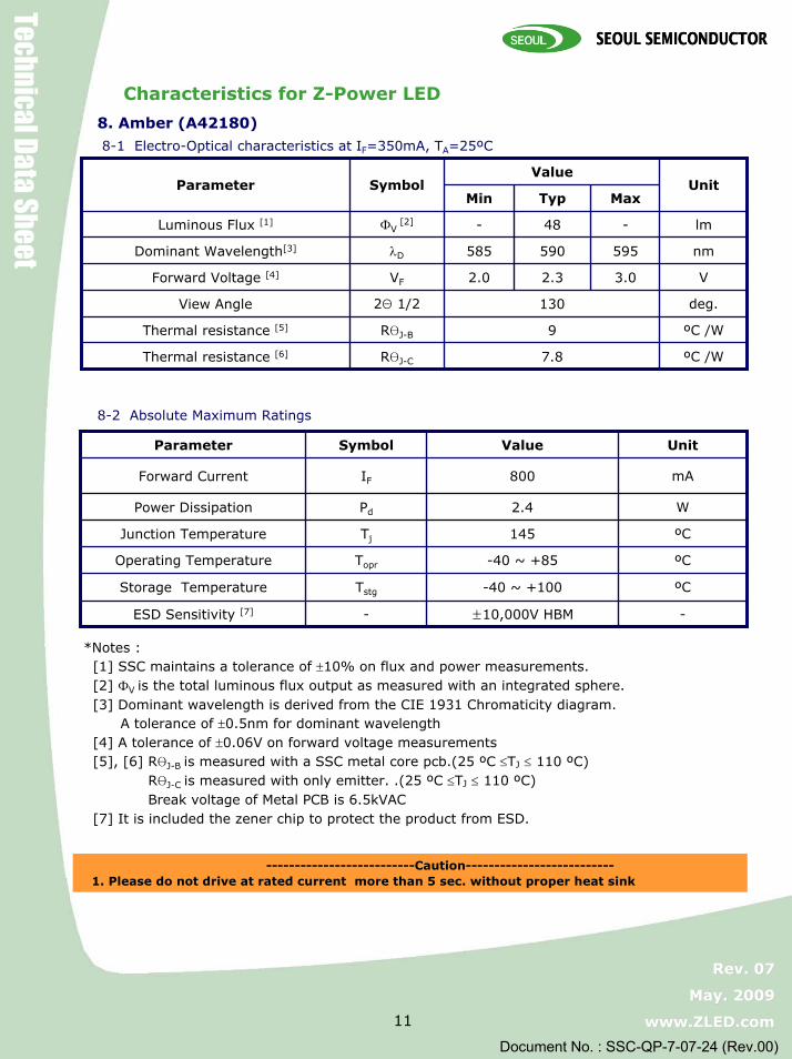
8. Amber (A42180)8-1 Electro-Optical characteristics at IF=350mA, TA=25ºC
8-2 Absolute Maximum Ratings
Op
ote1] SSC maintains a tolerance
ºC /W9RθJ-BThermal resistance [5]
deg.1302Θ 1/2View Angle
V3.02.32.0VFForward Voltage [4]
nm595590585λDDominant Wavelength[3]
MaxTypMin
-48
ºC /W7.8RθJ-CThermal resistance [6]
lm-ФV [2]Luminous Flux [1]
UnitValue
SymbolParameter
W2.4PdPower Dissipation
ºC145TjJunction Temperature
mA800IFForward Current
-±10,000V HBM-ESD Sensitivity [7]
ºC-40 ~ +100TstgStorage Temperature
ºC-40 ~ +85Toprerating Temperature
UnitValueSymbolParameter
*N s : [ of ±10% on flux and power measurements.[2] ФV is the total luminous flux output as measured with an integrated sphere.[3] Dominant wavelength is derived from the CIE 1931 Chromaticity diagram.
A tolerance of ±0.5nm for dominant wavelength[4] A tolerance of ±0.06V on forward voltage measurements[5], [6] RθJ-B is measured with a SSC metal core pcb.(25 ºC ≤TJ ≤ 110 ºC)
RθJ-C is measured with only emitter. .(25 ºC ≤TJ ≤ 110 ºC)Break voltage of Metal PCB is 6.5kVAC
[7] It is included the zener chip to protect the product from ESD.
--------------------------Caution--------------------------1. Please do not drive at rated current more than 5 sec. without proper heat sink

Z-Power LED X10490
Z-Power LED X10490
Technical Data Sheet
Rev. 07 Rev. 07
May. 2009 May. 2009
www.ZLED.com www.ZLED.com 12
Document No. : SSC-QP-7-07-24 (Rev.00)
1. Pure White
2. Warm White
3 0 0 4 0 0 5 0 0 6 0 0 7 0 0 8 0 00 .0
0 .2
0 .4
0 .6
0 .8
1 .0
Rel
ativ
e Sp
ectra
l Pow
er
W a v e le n g th
Color Spectrum, TA=25ºC
3 0 0 4 0 0 5 0 0 6 0 0 7 0 0 8 0 0 9 0 00 .0
0 .2
0 .4
0 .6
0 .8
1 .0 S ta n d a rd e ye re s p o n s e c u rv e
Rela
tive S
pect
ral
Po
wer
Dis
trib
uti
on
W a v e le n g th ( n m )

Z-Power LED X10490
Z-Power LED X10490
Technical Data Sheet
Rev. 07 Rev. 07
May. 2009 May. 2009
www.ZLED.com www.ZLED.com 13
Document No. : SSC-QP-7-07-24 (Rev.00)
3. Natural White
3 0 0 4 0 0 5 0 0 6 0 0 7 0 0 8 0 00 .0
0 .2
0 .4
0 .6
0 .8
1 .0
Rel
ativ
e S
pect
ral P
ower
W a v e le n g th
4. Red, Amber, Green, Blue(Royal Blue)
Color Spectrum, TA=25ºC
4 0 0 5 0 0 6 0 0 7 0 00 .0
0 .2
0 .4
0 .6
0 .8
1 .0
Rela
tive S
pect
ral
Po
wer
Dis
trib
uti
on
W a v e le n g th ( n m )

Z-Power LED X10490
Z-Power LED X10490
Technical Data Sheet
Rev. 07 Rev. 07
May. 2009 May. 2009
www.ZLED.com www.ZLED.com 14
Document No. : SSC-QP-7-07-24 (Rev.00)
Junction Temperature Characteristics
1. Relative Light Output vs. Junction Temperature at IF=350mA
25 50 75 100 125 1500
20
40
60
80
100
120
Rela
tive
Ligh
t Out
put(%
)
Junction Temperature(OC)
Natural White, Warm White Pure White Blue(Royal Blue) Green
25 50 75 100 125 1500
20
40
60
80
100
Rela
tive L
igh
t O
utp
ut
[%]
Junction Temperature [oC]
Red Amber

Z-Power LED X10490
Z-Power LED X10490
Technical Data Sheet
Rev. 07 Rev. 07
May. 2009 May. 2009
www.ZLED.com www.ZLED.com 15
Document No. : SSC-QP-7-07-24 (Rev.00)
3. Wavelength Shift vs Junction Temperature at IF=350mA
Junction Temperature Characteristics
2. Forward Voltage Shift vs. Junction Temperature at IF=350mA
25 50 75 100 125 1500
2
4
6
8
10
12
Dom
inan
t Wav
elen
gth
Shift
[nm
]
Junction Temperature[oC]
Red Green Blue(Royal Blue) Amber
25 50 75 100 125 150-1.0
-0.8
-0.6
-0.4
-0.2
0.0
Fo
rward
Vo
ltag
e S
hif
t[V
]
Junction Temperature [OC]
Pure White, Warm White, Natural White, Blue(Royal Blue) Red Amber Green

Z-Power LED X10490
Z-Power LED X10490
Technical Data Sheet
Rev. 07 Rev. 07
May. 2009 May. 2009
www.ZLED.com www.ZLED.com 16
Document No. : SSC-QP-7-07-24 (Rev.00)
0.0 0.5 1.0 1.5 2.0 2.5 3.0 3.5 4.00
200
400
600
800
1000 Blue(Royal Blue), Green, Pure White
Warm White, Natural White
A
vera
ge F
orw
ard
Cu
rren
t [m
A]
Forward Voltage [V]
Forward Current Characteristics
1. Forward Voltage vs. Forward Current , TA=25 ºc
0.0 0.5 1.0 1.5 2.0 2.5 3.00
100
200
300
400
500
600
700
800 Red, Amber
Avera
ge F
orw
ard
Cu
rren
t [m
A]
Forward Voltage [V]

Z-Power LED X10490
Z-Power LED X10490
Technical Data Sheet
Rev. 07 Rev. 07
May. 2009 May. 2009
www.ZLED.com www.ZLED.com 17
Document No. : SSC-QP-7-07-24 (Rev.00)
0 200 400 600 800 10000.0
0.5
1.0
1.5
2.0
2.5
Forward Current [mA]
Rela
tive L
um
iou
s Flu
x(a
.U)
Blue(Royal Blue), Green, Pure White Warm White, Natural White
Forward Current Characteristics
2. Forward Current vs. Normalized Relative Luminous Flux, TA=25 ºc
0 200 400 600 8000.0
0.5
1.0
1.5
2.0
2.5
Forward Current [mA]
Rela
tive L
um
iou
s Flu
x(a
.U)
Red, Amber
Z-Power LED X10490
Z-Power LED X10490
Technical Data Sheet
Rev. 07 Rev. 07
May. 2009 May. 2009
www.ZLED.com www.ZLED.com 18
Document No. : SSC-QP-7-07-24 (Rev.00)
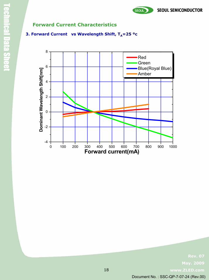
3. Forward Current vs Wavelength Shift, TA=25 ºc
Forward Current Characteristics
0 100 200 300 400 500 600 700 800 900 1000-4
-2
0
2
4
6
8
Dom
inan
t Wav
elen
gth
Shift
[nm
]
Forward current(mA)
Red Green Blue(Royal Blue) Amber
Z-Power LED X10490
Z-Power LED X10490
Technical Data Sheet
Rev. 07 Rev. 07
May. 2009 May. 2009
www.ZLED.com www.ZLED.com 19
Document No. : SSC-QP-7-07-24 (Rev.00)
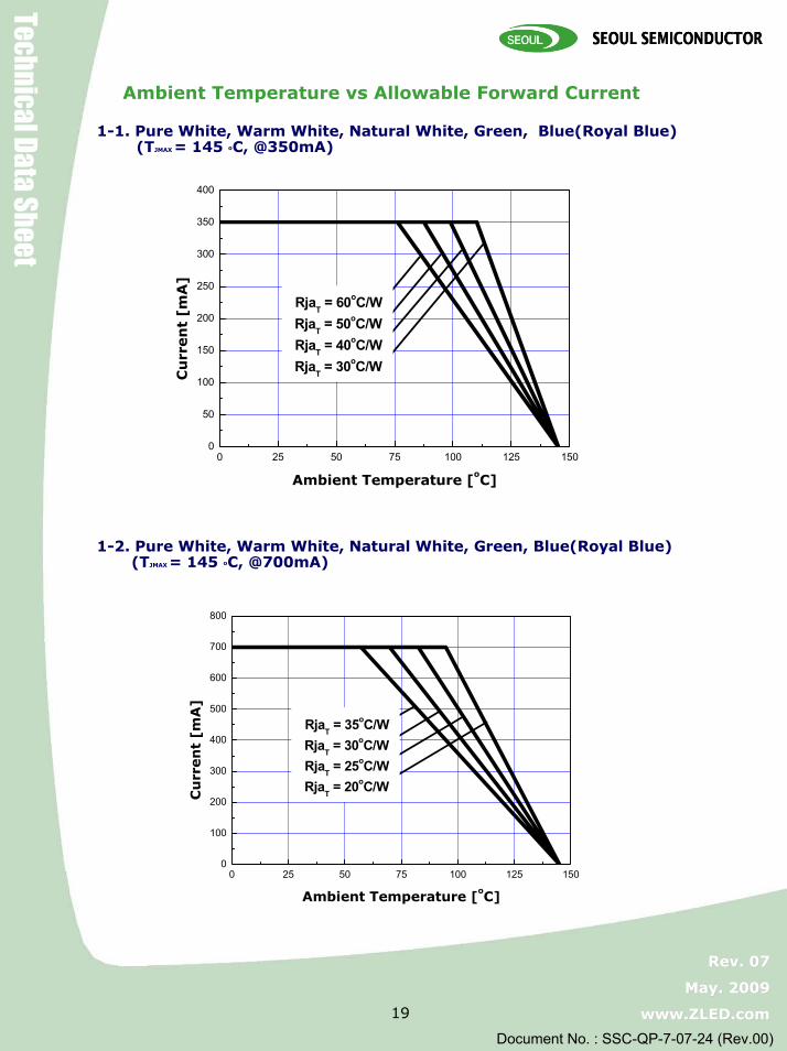
1-1. Pure White, Warm White, Natural White, Green, Blue(Royal Blue)(TJMAX = 145 ºC, @350mA)
1-2. Pure White, Warm White, Natural White, Green, Blue(Royal Blue)(TJMAX = 145 ºC, @700mA)
0 25 50 75 100 125 1500
50
100
150
200
250
300
350
400
RjaT = 60oC/W RjaT = 50oC/W RjaT = 40oC/W RjaT = 30oC/W
C
urr
en
t [m
A]
Ambient Temperature [oC]
0 25 50 75 100 125 1500
100
200
300
400
500
600
700
800
RjaT = 35oC/W RjaT = 30oC/W RjaT = 25oC/W RjaT = 20oC/W
Cu
rren
t [m
A]
Ambient Temperature [oC]
Ambient Temperature vs Allowable Forward Current

Z-Power LED X10490
Z-Power LED X10490
Technical Data Sheet
Rev. 07 Rev. 07
May. 2009 May. 2009
www.ZLED.com www.ZLED.com 20
Document No. : SSC-QP-7-07-24 (Rev.00)
1-3. Pure White, Green, Blue(Royal Blue)(TJMAX = 90 ºC, at 1000mA)
0 25 50 75 100 125 1500
200
400
600
800
1000
1200
RjaT = 25oC/W RjaT = 20oC/W
C
urr
en
t [m
A]
Ambient Temperature [oC]
Ambient Temperature vs Allowable Forward Current

Z-Power LED X10490
Z-Power LED X10490
Technical Data Sheet
Rev. 07 Rev. 07
May. 2009 May. 2009
www.ZLED.com www.ZLED.com 21
Document No. : SSC-QP-7-07-24 (Rev.00)
0 25 50 75 100 125 1500
100
200
300
400
RjaT = 60oC/W RjaT = 50oC/W RjaT = 40oC/W RjaT = 30oC/W
Cu
rren
t [m
A]
Ambient Temperature [oC]
1-4. Red, Amber (TJMAX = 145 ºC, at 350mA)
0 25 50 75 100 125 1500
100
200
300
400
500
600
700
800
RjaT = 60oC/W RjaT = 50oC/W RjaT = 40oC/W RjaT = 30oC/W
Cu
rren
t [m
A]
Ambient Temperature [oC]
1-5. Red, Amber(TJMAX = 145 ºC, @700mA)
Ambient Temperature vs Allowable Forward Current

Z-Power LED X10490
Z-Power LED X10490
Technical Data Sheet
Rev. 07 Rev. 07
May. 2009 May. 2009
www.ZLED.com www.ZLED.com 22
Document No. : SSC-QP-7-07-24 (Rev.00)
1. Pure White
2. Warm White, Natural White
0
30
60
90-80 -60 -40 -20 0
0.0
0.2
0.4
0.6
0.8
1.0
Rel
ativ
e Lu
min
ous
Flux
Angle(deg.)
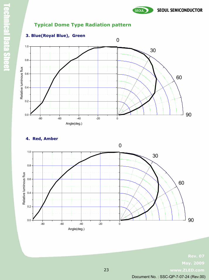
Typical Dome Type Radiation pattern
0
30
60
90-80 -60 -40 -20 0
0.0
0.2
0.4
0.6
0.8
1.0
Rel
ativ
e lu
min
ous
flux
Angle(deg.)
Z-Power LED X10490
Z-Power LED X10490
Technical Data Sheet
Rev. 07 Rev. 07
May. 2009 May. 2009
www.ZLED.com www.ZLED.com 23
Document No. : SSC-QP-7-07-24 (Rev.00)
3. Blue(Royal Blue), Green
4. Red, Amber
0
30
60
90
-80 -60 -40 -20 00.0
0.2
0.4
0.6
0.8
1.0
Rel
ativ
e lu
min
ous
flux
Angle(deg.)
0
30
60
90
-80 -60 -40 -20 00.0
0.2
0.4
0.6
0.8
1.0
Rel
ativ
e lu
min
ous
flux
Angle(deg.)
Typical Dome Type Radiation pattern

Z-Power LED X10490
Z-Power LED X10490
Technical Data Sheet
Rev. 07 Rev. 07
May. 2009 May. 2009
www.ZLED.com www.ZLED.com 24
Document No. : SSC-QP-7-07-24 (Rev.00)
1. Solder pad
2. Solder paste pattern
Recommended Solder pad
Note :
1. All dimensions are in millimeters (tolerance : ±0.2 )
2. Scale none
*The appearance and specifications of the product may be changed for improvement without notice.

Z-Power LED X10490
Z-Power LED X10490
Technical Data Sheet
Rev. 07 Rev. 07
May. 2009 May. 2009
www.ZLED.com www.ZLED.com 25
Document No. : SSC-QP-7-07-24 (Rev.00)
3. Reflow Soldering Conditions / Profile
4. Hand Soldering conditions
Lead : Not more than 3 seconds @MAX280℃
Slug : Use a thermal-adhesives
Pre-heating
200
180
150
~
0
220
240
260
Rising5 °C/sec
Tm : Reflow machine setting temp (max 30 sec.)
Ts : Surface temp of PCB (min)
Ts : Surface temp of PCB (max)Ts : Surface temp of PCB (recommend)
Cooling-5 °C/sec
Time
[Hr]
* Caution1. Reflow soldering should not be done more than one time.2. Repairing should not be done after the LEDs have been soldered.
When repairing is unavoidable, suitable tools have to be used. 3. Die slug is to be soldered.4. When soldering, do not put stress on the LEDs during heating.5. After soldering, do not warp the circuit board.6. Recommend to use a convection type reflow machine with 7 ~ 8 zones.
Z-Power LED X10490
Z-Power LED X10490
Technical Data Sheet
Rev. 07 Rev. 07
May. 2009 May. 2009
www.ZLED.com www.ZLED.com 26
Document No. : SSC-QP-7-07-24 (Rev.00)
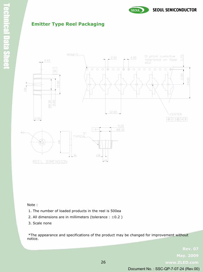
Note :
1. The number of loaded products in the reel is 500ea
2. All dimensions are in millimeters (tolerance : ±0.2 )
3. Scale none
*The appearance and specifications of the product may be changed for improvement without notice.
Emitter Type Reel Packaging

Z-Power LED X10490
Z-Power LED X10490
Technical Data Sheet
Rev. 07 Rev. 07
May. 2009 May. 2009
www.ZLED.com www.ZLED.com 27
Document No. : SSC-QP-7-07-24 (Rev.00)
Note :
1. 6~10 reels are loaded in box
2. Scale none
3. For more information about binning and labeling, refer to the Application Note - 1
a
ZLED
b
c
Outer Box
Aluminum Vinyl Bag
ba c
SEOUL SEMICONDUCTOR CO.,LTD
PART : W42180-**
LOT NO : YMDD-#####Q'YT : ######PO CODE : ##
DATE : ######
ZLED
350 350 370
SIZE(mm)TYPE
LOT NUMBER : #######-#######
PART NO. : ######-##
BIN CODE : #######
QUANTITY : ***
Packaging Structure
Z-Power LED X10490
Z-Power LED X10490
Technical Data Sheet
Rev. 07 Rev. 07
May. 2009 May. 2009
www.ZLED.com www.ZLED.com 28
Document No. : SSC-QP-7-07-24 (Rev.00)
• Storage
To avoid the moisture penetration, we recommend storing Z Power LEDs in a dry box
(or desiccator) with a desiccant . The recommended storage conditions are Temperature 5 to 30
degrees Centigrade. Humidity 50% maximum.
• Precaution after opening packaging
However LED is correspond SMD, when LED be soldered dip, interfacial separation may affect
the light transmission efficiency, causing the light intensity to drop.
Attention in followed.
a. Soldering should be done right after opening the package(within 24Hrs).
b. Keeping of a fraction
- Sealing
- Temperature : 5 ~ 40℃ Humidity : less than 30%
c. If the package has been opened more than 1week or the color of desiccant changes,
components should be dried for 10-12hr at 60±5℃
• Any mechanical force or any excess vibration shall not be accepted to apply during cooling
process to normal temp. after soldering.
• Please avoid rapid cooling after soldering.
• Components should not be mounted on warped direction of PCB.
• Anti radioactive ray design is not considered for the products listed here in.
• Gallium arsenide is used in some of the products listed in this publication. These products are
dangerous if they are burned or shredded in the process of disposal. It is also dangerous to
drink the liquid or inhale the gas generated by such products when chemically disposed.
• This device should not be used in any type of fluid such as water, oil, organic solvent and etc.
When washing is required, IPA(Isopropyl Alcohol) should be used.
• When the LEDs are illuminating, operating current should be decided after considering the
package maximum temperature.
• LEDs must be stored to maintain a clean atmosphere. If the LEDs are stored for 3 months or
more after being shipped from SSC, a sealed container with a nitrogen atmosphere should be used for storage.
• The appearance and specifications of the product may be modified for improvement without
notice.
• Long time exposure of sunlight or occasional UV exposure will cause lens discoloration.
• The slug is connected to the anode. Therefore, we recommend to isolate the heat sink.
• Attaching LEDs, don’t use adhesives to generate organic vapor.
precaution for use

Z-Power LED X10490
Z-Power LED X10490
Technical Data Sheet
Rev. 07 Rev. 07
May. 2009 May. 2009
www.ZLED.com www.ZLED.com 29
Document No. : SSC-QP-7-07-24 (Rev.00)
Z-Power LED is encapsulated by silicone resin for the highest flux efficiency.Notes for handling of Silicone resin Z-Power LEDs• Avoid touching silicone resin parts especially by sharp tools such as Pincette(Tweezers)• Avoid leaving fingerprints on silicone resin parts.• Dust sensitivity silicone resin need containers having cover for storage.• When populating boards in SMT production, there are basically no restrictions
regarding the form of the pick and place nozzle, except that mechanical pressure on the surface of the resin must be prevent.
• Please do not force over 2000 gf impact or pressure diagonally on the silicon lens.It will cause fatal damage of this product
• Please do not recommend to cover the silicone resin of the LEDs with other resin (epoxy, urethane, etc)
Handling of Silicone resin LEDs


![VebraAlto.com - Agency Cloud2d4233eac846bc0f89e3-0ef12140d803ffe0f177b474e8de00ef.r19.cf3.rackcdn.… · îõ W µ ,]ooZ} U,ÇÁ , ZUt ^µ ÆUZ,íòí>z tZ Á o]l XXX W }( o À o}](https://img.pdfslide.us/doc/110x75/5e1ea556e31a545b9d7b6e9b/-agency-cloud2d4233eac846bc0f89e3-0ef12140d803ffe0f177b474e8de00efr19cf3rackcdn.jpg)


![Microsoft power point_çá·¹á¨å×àì¼ç[1]](https://img.pdfslide.us/doc/110x75/55c325f0bb61eb55348b458b/microsoft-power-pointcaaaaic1-55c45886c4b1e.jpg)