Embed Size (px)
Citation preview
PowerMatch®
Configurable Professional Power Amplifiers
Installation and Operating Guide
PM8500 / PM8500N
PM8250 / PM8250N
PM4500 / PM4500N
PM4250 / PM4250N

English UserGuide Page3
pro.Bose.com Contents
Introduction .................................................................................................................................................... 12
Product Features .......................................................................................................................................... 12
PowerMatch® Amplifier Line Overview ................................................................................................. 13
PowerMatch configurable professional power amplifiers ...................................................................... 13
Onboard Loudspeaker Processing and Front Panel Interface ............................................................... 13
Accessory Cards .................................................................................................................................... 13
Ideal for use with RoomMatch® array module loudspeakers .................................................................. 13
Interfacing with ControlSpace® engineered sound processors .............................................................. 13
Controls, Display, and Connectors ......................................................................................................... 14
Hardware Installation .................................................................................................................................. 15
Unpacking............................................................................................................................................... 15
Ventilation ............................................................................................................................................... 15
AC Mains Outlet Requirements .............................................................................................................. 15
Making Connections ................................................................................................................................... 16
Connection and Configuration Steps ..................................................................................................... 16
Power (Mains) Connection ...................................................................................................................... 16
Standby Mode ........................................................................................................................................ 16
Wiring Input Connectors ......................................................................................................................... 17
Wiring Output Connectors ...................................................................................................................... 17
Fault Notification Output ........................................................................................................................ 19
Serial over Ethernet ................................................................................................................................ 19
Setup and Configuration ........................................................................................................................... 20
Configuration Methods ........................................................................................................................... 20
Control Panel Description ....................................................................................................................... 21
Front Panel Control Menu Structure ....................................................................................................... 22
Control Menu Descriptions ..................................................................................................................... 22
Setting the Limiting Function for use with 3rd Party Loudspeakers ....................................................... 34
Sample Output Configurations for Different Loudspeaker Loads ............................................... 35
Configuration of a RoomMatch Two-Module Array (Example 1) ............................................................ 35
Configuration of a RoomMatch RMS215 Subwoofer Module (Example 2) ............................................ 35
Maintenance Operations ........................................................................................................................... 36
Updating Firmware and Speaker EQ Presets ......................................................................................... 36
Saving and Recalling Amplifier Settings (USB-only version amplifiers) ................................................. 37
Saving and Recalling Amplifier Settings (network version amplifiers) .................................................... 37
About the Alarm Log and Fault Indicator ................................................................................................ 38
Troubleshooting ............................................................................................................................................ 39
Appendix ......................................................................................................................................................... 40
Interface Comparison Table .................................................................................................................... 40
Technical Specifications ........................................................................................................................ 41
AC Current Draw and Thermal Dissipation Information ......................................................................... 46
Important Safety Information pro.Bose.com
Page4 InstallationandSafetyGuidelines English
WARNING: This product is intended for installation by professional installers only.
Thank you for selecting Bose® PowerMatch® amplifiers for your sound reinforcement system. This document is intended to provide professional installers with basic installation and safety guidelines for Bose PowerMatch amplifiers in typical fixed-installation systems. Please read this document before attempting installation.
WARNING: Do not expose this apparatus to dripping or splashing, and do not place objects filled with liquids such as vases, on or near the apparatus. As with any electronic products, use care not to spill liquids into any part of the system. Liquids can cause a failure and/or a fire hazard.
WARNING: To reduce the risk of fire or electric shock, do not expose this apparatus to rain.
WARNING: Do not place any naked flame sources, such as lighted candles, on or near the apparatus.
Note: The product must be used indoors. It is neither designed nor tested for use outdoors, in recreational vehicles, or on boats.
The lightning flash with arrowhead symbol, within an equilateral triangle, is intended to alert the user to the presence of uninsu-lated dangerous voltage within the system enclosure that may be of sufficient magnitude to constitute a risk of electrical shock. Do not touch the output terminals while amplifier power is ON. Make all connections with amplifier OFF.
The exclamation point within an equilateral triangle, as marked on the system, is intended to alert the user to the presence of important operating and maintenance instructions in this installation guide.
CAUTION: Make no modifications to the amplifier or accessories. Unauthorized alternations may compromise safety, regulatory compliance, and system performance.
CAUTION: This product shall be connected to an AC mains socket outlet with a protective earthing (grounding) connection.
CAUTION: Where the AC mains plug is used as the disconnect device, such disconnect device shall remain fully operable.
Important Safety Instructions1. Read these instructions.
2. Keep these instructions – for future reference.
3. Heed all warnings – on the product and in all product documentation.
4. Follow all instructions.
5. Do not use this apparatus near water or moisture.
6. Clean only with a dry cloth.
7. Do not block any ventilation openings. Install in accordance with the manufacturer’s instructions. To ensure reliable operation of the product and to protect it from overheating, put the product in a position and location that will not interfere with its proper ventilation.
8. Do not install near any heat sources, such as radiators, heat registers, stoves, or other apparatus (including amplifiers) that produce heat.
9. Do not defeat the safety purpose of the polarized or grounding-type plug. A polarized plug has two blades with one wider than the other. A grounding-type plug has two blades and a third grounding prong. The wider blade or third prong is provided for your safety. If the provided plug does not fit in your outlet, consult an electrician for replacement of the obsolete outlet.
10. Protect the power cord from being walked on or pinched, particularly at plugs, convenience receptacles, and the point where they exit from the apparatus.
11. Only use attachments/accessories specified by the manufacturer.
12. Use only with the cart, stand, tripod, bracket, or table specified by the manufacturer or sold with the apparatus. When a cart is used, use caution when moving the cart/apparatus combination to avoid injury from tip-over.

English InstallationandSafetyGuidelines Page5
pro.Bose.com Important Safety Information
13. Unplug this apparatus during lightning storms or when unused for long periods of time to prevent damage to this product.
14. Refer all servicing to qualified service personnel. Servicing is required when the apparatus has been damaged in any way such as power-supply cord or plug is damaged; liquid has been spilled or objects have fallen into the apparatus; the apparatus has been exposed to rain or moisture, does not operate normally, or has been dropped. Do not attempt to service this product yourself. Opening or removing covers may expose you to dangerous voltages or other hazards. Please call Bose to be referred to an authorized service center near you.
15. To prevent risk of fire or electric shock, avoid overloading wall outlets, extension cords, or integral convenience receptacles.
16. Do not let objects or liquids enter the product – as they may touch dangerous voltage points or short-out parts that could result in a fire or electric shock.
17. See product enclosure for safety-related markings.
18. The front panel LCD screen will illuminate when the product has mains power. If power is applied and the LCD screen is not illuminated, please send the unit for service.
19. Do not allow the unit to exceed the maximum operating ambient temperature of 40° C. Be aware of conditions in an enclosed rack that may increase the temperature above room ambient conditions.
This product conforms to all applicable EU directive requirements. The complete declaration of conformity can be found at www.Bose.com/compliance.
This Product meets the immunity requirements for the E2 class EN55103-2 directive.
Initial turn on inrush current: 14.8 Amps (230V / 50 Hz)
Inrush current after 5 seconds AC mains interruption: 15.4 Amps (230V / 50 Hz)
Information About Products That Generate Electrical Noise (FCC Compliance Notice for U.S.)
Note: This equipment has been tested and found to comply with the limits for a Class A digital device, pursuant to part 15 of the FCC Rules. These limits are designed to provide reasonable protection against harmful interference when the equipment is operated in a commercial environment. This equipment generates, uses, and can radiate radio frequency energy and, if not installed and used in accordance with the instruction manual, may cause harmful interference to radio communications. Operation of this equipment in a residential area is likely to cause harmful interference in which case the user will be required to correct the interference at one’s own expense.
This product complies with CAN ICES-3 (A)/NMB-3 (A).

Información de seguridad importante pro.Bose.com
Página6 Instruccionesdeinstalaciónydeseguridad Español
WARNING: This product is intended for installation by professional installers only.
Thank you for selecting Bose® PowerMatch® amplifiers for your sound reinforcement system. This document is intended to provide professional installers with basic installation and safety guidelines for Bose PowerMatch amplifiers in typical fixed-installation systems. Please read this document before attempting installation.
WARNING: Do not expose this apparatus to dripping or splashing, and do not place objects filled with liquids such as vases, on or near the apparatus. As with any electronic products, use care not to spill liquids into any part of the system. Liquids can cause a failure and/or a fire hazard.
WARNING: To reduce the risk of fire or electric shock, do not expose this apparatus to rain.
WARNING: Do not place any naked flame sources, such as lighted candles, on or near the apparatus.
Note: The product must be used indoors. It is neither designed nor tested for use outdoors, in recreational vehicles, or on boats.
The lightning flash with arrowhead symbol, within an equilateral triangle, is intended to alert the user to the presence of uninsu-lated dangerous voltage within the system enclosure that may be of sufficient magnitude to constitute a risk of electrical shock. Do not touch the output terminals while amplifier power is ON. Make all connections with amplifier OFF.
The exclamation point within an equilateral triangle, as marked on the system, is intended to alert the user to the presence of important operating and maintenance instructions in this installation guide.
CAUTION: Make no modifications to the amplifier or accessories. Unauthorized alternations may compromise safety, regulatory compliance, and system performance.
CAUTION: This product shall be connected to an AC mains socket outlet with a protective earthing (grounding) connection.
CAUTION: Where the AC mains plug is used as the disconnect device, such disconnect device shall remain fully operable.
Important Safety Instructions1. Read these instructions.
2. Keep these instructions – for future reference.
3. Heed all warnings – on the product and in all product documentation.
4. Follow all instructions.
5. Do not use this apparatus near water or moisture.
6. Clean only with a dry cloth.
7. Do not block any ventilation openings. Install in accordance with the manufacturer’s instructions. To ensure reliable operation of the product and to protect it from overheating, put the product in a position and location that will not interfere with its proper ventilation.
8. Do not install near any heat sources, such as radiators, heat registers, stoves, or other apparatus (including amplifiers) that produce heat.
9. Do not defeat the safety purpose of the polarized or grounding-type plug. A polarized plug has two blades with one wider than the other. A grounding-type plug has two blades and a third grounding prong. The wider blade or third prong is provided for your safety. If the provided plug does not fit in your outlet, consult an electrician for replacement of the obsolete outlet.
10. Protect the power cord from being walked on or pinched, particularly at plugs, convenience receptacles, and the point where they exit from the apparatus.
11. Only use attachments/accessories specified by the manufacturer.
12. Use only with the cart, stand, tripod, bracket, or table specified by the manufacturer or sold with the apparatus. When a cart is used, use caution when moving the cart/apparatus combination to avoid injury from tip-over.
pro.Bose.com

Español Instruccionesdeinstalaciónydeseguridad Página7
pro.Bose.com Información de seguridad importante
13. Unplug this apparatus during lightning storms or when unused for long periods of time to prevent damage to this product.
14. Refer all servicing to qualified service personnel. Servicing is required when the apparatus has been damaged in any way such as power-supply cord or plug is damaged; liquid has been spilled or objects have fallen into the apparatus; the apparatus has been exposed to rain or moisture, does not operate normally, or has been dropped. Do not attempt to service this product yourself. Opening or removing covers may expose you to dangerous voltages or other hazards. Please call Bose to be referred to an authorized service center near you.
15. To prevent risk of fire or electric shock, avoid overloading wall outlets, extension cords, or integral convenience receptacles.
16. Do not let objects or liquids enter the product – as they may touch dangerous voltage points or short-out parts that could result in a fire or electric shock.
17. See product enclosure for safety-related markings.
18. The front panel LCD screen will illuminate when the product has mains power. If power is applied and the LCD screen is not illuminated, please send the unit for service.
19. Do not allow the unit to exceed the maximum operating ambient temperature of 40° C. Be aware of conditions in an enclosed rack that may increase the temperature above room ambient conditions.
This product conforms to all applicable EU directive requirements. The complete declaration of conformity can be found at www.Bose.com/compliance.
This Product meets the immunity requirements for the E2 class EN55103-2 directive.
Initial turn on inrush current: 14.8 Amps (230V / 50 Hz)
Inrush current after 5 seconds AC mains interruption: 15.4 Amps (230V / 50 Hz)
Information About Products That Generate Electrical Noise (FCC Compliance Notice for U.S.)
Note: This equipment has been tested and found to comply with the limits for a Class A digital device, pursuant to part 15 of the FCC Rules. These limits are designed to provide reasonable protection against harmful interference when the equipment is operated in a commercial environment. This equipment generates, uses, and can radiate radio frequency energy and, if not installed and used in accordance with the instruction manual, may cause harmful interference to radio communications. Operation of this equipment in a residential area is likely to cause harmful interference in which case the user will be required to correct the interference at one’s own expense.
This product complies with CAN ICES-3 (A)/NMB-3 (A).
Informations importantes pour la sécurité pro.Bose.com
Page8 Installationetinstructionsdesécurité Français
WARNING: This product is intended for installation by professional installers only.
Thank you for selecting Bose® PowerMatch® amplifiers for your sound reinforcement system. This document is intended to provide professional installers with basic installation and safety guidelines for Bose PowerMatch amplifiers in typical fixed-installation systems. Please read this document before attempting installation.
WARNING: Do not expose this apparatus to dripping or splashing, and do not place objects filled with liquids such as vases, on or near the apparatus. As with any electronic products, use care not to spill liquids into any part of the system. Liquids can cause a failure and/or a fire hazard.
WARNING: To reduce the risk of fire or electric shock, do not expose this apparatus to rain.
WARNING: Do not place any naked flame sources, such as lighted candles, on or near the apparatus.
Note: The product must be used indoors. It is neither designed nor tested for use outdoors, in recreational vehicles, or on boats.
The lightning flash with arrowhead symbol, within an equilateral triangle, is intended to alert the user to the presence of uninsu-lated dangerous voltage within the system enclosure that may be of sufficient magnitude to constitute a risk of electrical shock. Do not touch the output terminals while amplifier power is ON. Make all connections with amplifier OFF.
The exclamation point within an equilateral triangle, as marked on the system, is intended to alert the user to the presence of important operating and maintenance instructions in this installation guide.
CAUTION: Make no modifications to the amplifier or accessories. Unauthorized alternations may compromise safety, regulatory compliance, and system performance.
CAUTION: This product shall be connected to an AC mains socket outlet with a protective earthing (grounding) connection.
CAUTION: Where the AC mains plug is used as the disconnect device, such disconnect device shall remain fully operable.
Important Safety Instructions1. Read these instructions.
2. Keep these instructions – for future reference.
3. Heed all warnings – on the product and in all product documentation.
4. Follow all instructions.
5. Do not use this apparatus near water or moisture.
6. Clean only with a dry cloth.
7. Do not block any ventilation openings. Install in accordance with the manufacturer’s instructions. To ensure reliable operation of the product and to protect it from overheating, put the product in a position and location that will not interfere with its proper ventilation.
8. Do not install near any heat sources, such as radiators, heat registers, stoves, or other apparatus (including amplifiers) that produce heat.
9. Do not defeat the safety purpose of the polarized or grounding-type plug. A polarized plug has two blades with one wider than the other. A grounding-type plug has two blades and a third grounding prong. The wider blade or third prong is provided for your safety. If the provided plug does not fit in your outlet, consult an electrician for replacement of the obsolete outlet.
10. Protect the power cord from being walked on or pinched, particularly at plugs, convenience receptacles, and the point where they exit from the apparatus.
11. Only use attachments/accessories specified by the manufacturer.
12. Use only with the cart, stand, tripod, bracket, or table specified by the manufacturer or sold with the apparatus. When a cart is used, use caution when moving the cart/apparatus combination to avoid injury from tip-over.

Français Installationetinstructionsdesécurité Page9
pro.Bose.com Informations importantes pour la sécurité
13. Unplug this apparatus during lightning storms or when unused for long periods of time to prevent damage to this product.
14. Refer all servicing to qualified service personnel. Servicing is required when the apparatus has been damaged in any way such as power-supply cord or plug is damaged; liquid has been spilled or objects have fallen into the apparatus; the apparatus has been exposed to rain or moisture, does not operate normally, or has been dropped. Do not attempt to service this product yourself. Opening or removing covers may expose you to dangerous voltages or other hazards. Please call Bose to be referred to an authorized service center near you.
15. To prevent risk of fire or electric shock, avoid overloading wall outlets, extension cords, or integral convenience receptacles.
16. Do not let objects or liquids enter the product – as they may touch dangerous voltage points or short-out parts that could result in a fire or electric shock.
17. See product enclosure for safety-related markings.
18. The front panel LCD screen will illuminate when the product has mains power. If power is applied and the LCD screen is not illuminated, please send the unit for service.
19. Do not allow the unit to exceed the maximum operating ambient temperature of 40° C. Be aware of conditions in an enclosed rack that may increase the temperature above room ambient conditions.
This product conforms to all applicable EU directive requirements. The complete declaration of conformity can be found at www.Bose.com/compliance.
This Product meets the immunity requirements for the E2 class EN55103-2 directive.
Initial turn on inrush current: 14.8 Amps (230V / 50 Hz)
Inrush current after 5 seconds AC mains interruption: 15.4 Amps (230V / 50 Hz)
Information About Products That Generate Electrical Noise (FCC Compliance Notice for U.S.)
Note: This equipment has been tested and found to comply with the limits for a Class A digital device, pursuant to part 15 of the FCC Rules. These limits are designed to provide reasonable protection against harmful interference when the equipment is operated in a commercial environment. This equipment generates, uses, and can radiate radio frequency energy and, if not installed and used in accordance with the instruction manual, may cause harmful interference to radio communications. Operation of this equipment in a residential area is likely to cause harmful interference in which case the user will be required to correct the interference at one’s own expense.
This product complies with CAN ICES-3 (A)/NMB-3 (A).
Wichtige Sicherheitshinweise pro.Bose.com
Seite10 Installations-undSicherheitshinweise Deutsch
WARNING: This product is intended for installation by professional installers only.
Thank you for selecting Bose® PowerMatch® amplifiers for your sound reinforcement system. This document is intended to provide professional installers with basic installation and safety guidelines for Bose PowerMatch amplifiers in typical fixed-installation systems. Please read this document before attempting installation.
WARNING: Do not expose this apparatus to dripping or splashing, and do not place objects filled with liquids such as vases, on or near the apparatus. As with any electronic products, use care not to spill liquids into any part of the system. Liquids can cause a failure and/or a fire hazard.
WARNING: To reduce the risk of fire or electric shock, do not expose this apparatus to rain.
WARNING: Do not place any naked flame sources, such as lighted candles, on or near the apparatus.
Note: The product must be used indoors. It is neither designed nor tested for use outdoors, in recreational vehicles, or on boats.
The lightning flash with arrowhead symbol, within an equilateral triangle, is intended to alert the user to the presence of uninsu-lated dangerous voltage within the system enclosure that may be of sufficient magnitude to constitute a risk of electrical shock. Do not touch the output terminals while amplifier power is ON. Make all connections with amplifier OFF.
The exclamation point within an equilateral triangle, as marked on the system, is intended to alert the user to the presence of important operating and maintenance instructions in this installation guide.
CAUTION: Make no modifications to the amplifier or accessories. Unauthorized alternations may compromise safety, regulatory compliance, and system performance.
CAUTION: This product shall be connected to an AC mains socket outlet with a protective earthing (grounding) connection.
CAUTION: Where the AC mains plug is used as the disconnect device, such disconnect device shall remain fully operable.
Important Safety Instructions1. Read these instructions.
2. Keep these instructions – for future reference.
3. Heed all warnings – on the product and in all product documentation.
4. Follow all instructions.
5. Do not use this apparatus near water or moisture.
6. Clean only with a dry cloth.
7. Do not block any ventilation openings. Install in accordance with the manufacturer’s instructions. To ensure reliable operation of the product and to protect it from overheating, put the product in a position and location that will not interfere with its proper ventilation.
8. Do not install near any heat sources, such as radiators, heat registers, stoves, or other apparatus (including amplifiers) that produce heat.
9. Do not defeat the safety purpose of the polarized or grounding-type plug. A polarized plug has two blades with one wider than the other. A grounding-type plug has two blades and a third grounding prong. The wider blade or third prong is provided for your safety. If the provided plug does not fit in your outlet, consult an electrician for replacement of the obsolete outlet.
10. Protect the power cord from being walked on or pinched, particularly at plugs, convenience receptacles, and the point where they exit from the apparatus.
11. Only use attachments/accessories specified by the manufacturer.
12. Use only with the cart, stand, tripod, bracket, or table specified by the manufacturer or sold with the apparatus. When a cart is used, use caution when moving the cart/apparatus combination to avoid injury from tip-over.

Deutsch Installations-undSicherheitshinweise Seite11
pro.Bose.com Wichtige Sicherheitshinweise
13. Unplug this apparatus during lightning storms or when unused for long periods of time to prevent damage to this product.
14. Refer all servicing to qualified service personnel. Servicing is required when the apparatus has been damaged in any way such as power-supply cord or plug is damaged; liquid has been spilled or objects have fallen into the apparatus; the apparatus has been exposed to rain or moisture, does not operate normally, or has been dropped. Do not attempt to service this product yourself. Opening or removing covers may expose you to dangerous voltages or other hazards. Please call Bose to be referred to an authorized service center near you.
15. To prevent risk of fire or electric shock, avoid overloading wall outlets, extension cords, or integral convenience receptacles.
16. Do not let objects or liquids enter the product – as they may touch dangerous voltage points or short-out parts that could result in a fire or electric shock.
17. See product enclosure for safety-related markings.
18. The front panel LCD screen will illuminate when the product has mains power. If power is applied and the LCD screen is not illuminated, please send the unit for service.
19. Do not allow the unit to exceed the maximum operating ambient temperature of 40° C. Be aware of conditions in an enclosed rack that may increase the temperature above room ambient conditions.
This product conforms to all applicable EU directive requirements. The complete declaration of conformity can be found at www.Bose.com/compliance.
This Product meets the immunity requirements for the E2 class EN55103-2 directive.
Initial turn on inrush current: 14.8 Amps (230V / 50 Hz)
Inrush current after 5 seconds AC mains interruption: 15.4 Amps (230V / 50 Hz)
Information About Products That Generate Electrical Noise (FCC Compliance Notice for U.S.)
Note: This equipment has been tested and found to comply with the limits for a Class A digital device, pursuant to part 15 of the FCC Rules. These limits are designed to provide reasonable protection against harmful interference when the equipment is operated in a commercial environment. This equipment generates, uses, and can radiate radio frequency energy and, if not installed and used in accordance with the instruction manual, may cause harmful interference to radio communications. Operation of this equipment in a residential area is likely to cause harmful interference in which case the user will be required to correct the interference at one’s own expense.
This product complies with CAN ICES-3 (A)/NMB-3 (A).

Page12 UserGuide English
Installation and Operating Guide pro.Bose.com
IntroductionThank you for choosing Bose® PowerMatch® configurable professional power amplifiers.
PowerMatch® power amplifiers deliver concert-quality sound for a wide variety of fixed-installation sound reinforcement systems and provide class-leading efficiency, sound quality, and reliability.
Two documents are available to assist with amplifier installation and configuration. This document delivers detailed installation and standalone configuration information. A separate document, the ControlSpace® Designer™ Software Guide (downloadable from pro.Bose.com), provides detailed instructions on how to use ControlSpace Designer software to fully configure, monitor, and update PowerMatch amplifiers. For network version amplifiers, Designer software provides additional network setup, control, and monitoring capabilities.
Information furnished in these guides is intended to help professionals install and set up the product, but does not include all details of design, production, or variations of equipment. Nor does it cover every possible situation that may arise during installation, operation, or maintenance. If assistance is required beyond the scope of these documents, please contact your local Bose Representative or Technical Support specialist.
Product Features• PowerMatch amplifier series
Four amplifier models provide multiple channel and power options to satisfy the needs of almost any audio installation. Models include options for 4 or 8 channel versions and 250 or 500 watt per channel power levels. Additionally, network versions add control and monitoring functionality over standard Ethernet networks.
• PowerMatch Class-D AmplifierProprietary design combines Class-D efficiency with a dual current and voltage feedback loop circuit that continuously monitors and controls both the current and voltage delivered to the loudspeaker load. This combination allows the amplifier to consistently deliver the widest possible dynamic range, frequency response, and lowest possible distortion, independent of power level and load impedance.
• QuadBridge™ Output ConfigurationEach loudspeaker output terminal can be configured as Mono, V-Bridge, I-Share or Quad, allowing the total available power of the amplifier bank to be allocated to one or more output channels. V-Bridge and Quad modes can drive either low-impedance or 70/100V loads. Configuration of the loudspeaker output can be accessed from either the front panel of the amplifier or using ControlSpace Designer software.
• PeakBank™ Power SupplyRegenerative 4-quadrant power supply with fast-tracking Power Factor Correction (PFC) supports high efficiency while delivering sustainable and repeatable low frequency response.
• Integrated DSPA configurable fixed-architecture DSP provides multiple EQ stages, crossovers, delays, limiters, and matrix mixing. While PowerMatch can drive nearly any loudspeaker for the installed sound market, pre-loaded loudspeaker EQs and limiting presets for Bose loudspeakers provide an additional layer of simplified setup and premium sound. Amplifier models PM8500 and PM4500 feature power levels and array EQ features ideal for use with RoomMatch® array module loudspeakers and subwoofers.
• ControlSpace® Designer™ Software SetupAll models offer front panel USB connectivity for Bose ControlSpace Designer software programming, with network versions adding Ethernet network setup, control, and monitoring.
• Front Panel User InterfaceCombined front panel LCD and user controls provide useful visual information and access to a subset of amplifier settings suffi-cient for basic amplifier output configuration and status/fault monitoring. A convenient panel lock can be set to prevent access to unauthorized users.
• Network Control and MonitoringNetwork versions support a set of remote monitoring and fault reporting capabilities via the rear panel RJ45 Ethernet connection and Bose ControlSpace Designer software. A fault reporting and control protocol using Serial over Ethernet allows third party control and monitoring systems to communicate easily with one or many PowerMatch amplifiers.
• Load Sweep ToolUsing ControlSpace Designer software, the amplifier can measure the load impedance of each low impedance-configured output for system diagnostic and documentation purposes. The load measurement can be stored inside the amplifier and recalled as a reference curve for future comparisons to determine if the system is still operating as expected.
• Digital Expansion SlotOptional digital cards expand the input capabilities of PowerMatch® amplifiers, enabling the amplifiers to receive digital audio from Bose ESPLink-equipped devices and popular digital audio networks.
• Auto-Standby / Auto-WakeEnergy saving feature that allows PowerMatch amplifiers to automatically go into a lower power Standby Mode when audio signal falls below a set threshold, and wake up when audio signal is above threshold. All parameters, including time and audio detection levels are adjustable from within ControlSpace® Designer™ software.
English UserGuide Page13
pro.Bose.com Installation and Operating Guide
PowerMatch® Amplifier Line OverviewPowerMatch configurable professional power amplifiers
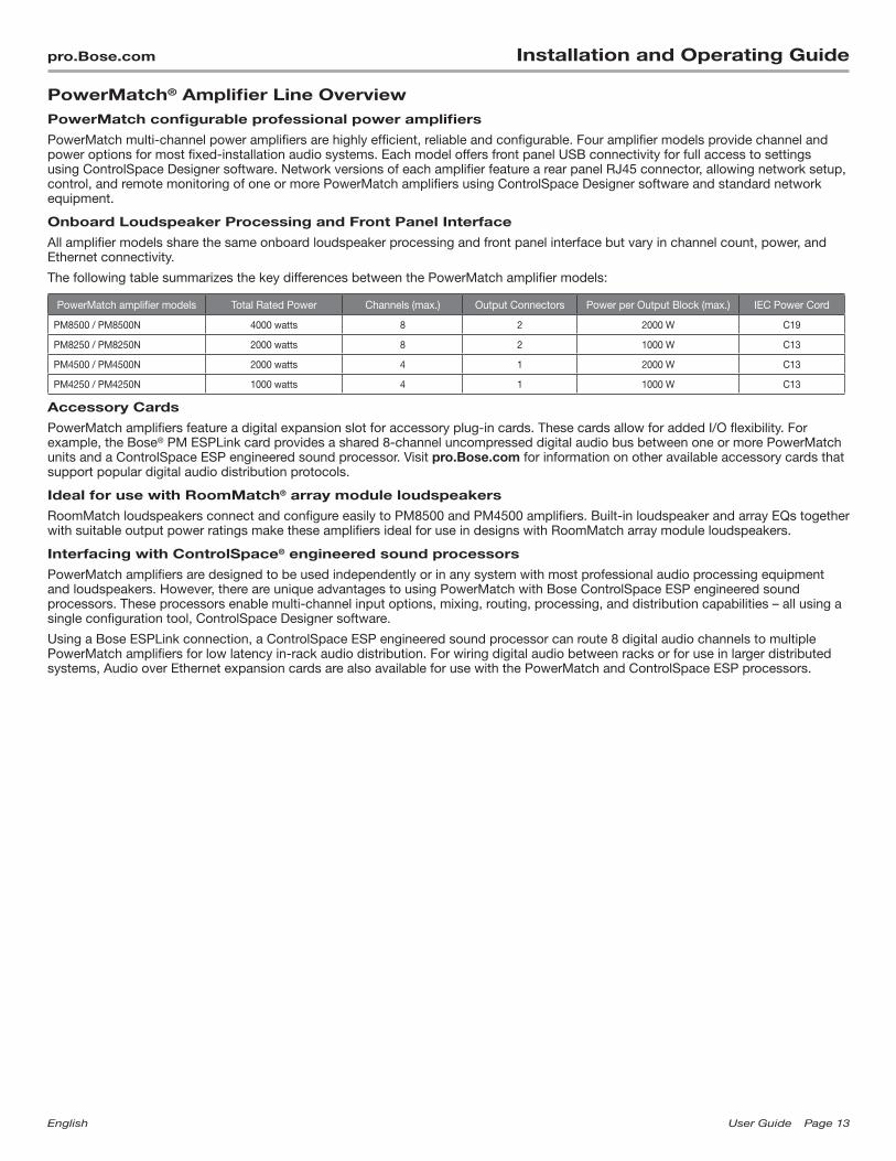
PowerMatch multi-channel power amplifiers are highly efficient, reliable and configurable. Four amplifier models provide channel and power options for most fixed-installation audio systems. Each model offers front panel USB connectivity for full access to settings using ControlSpace Designer software. Network versions of each amplifier feature a rear panel RJ45 connector, allowing network setup, control, and remote monitoring of one or more PowerMatch amplifiers using ControlSpace Designer software and standard network equipment.
Onboard Loudspeaker Processing and Front Panel Interface
All amplifier models share the same onboard loudspeaker processing and front panel interface but vary in channel count, power, and Ethernet connectivity.
The following table summarizes the key differences between the PowerMatch amplifier models:
PowerMatch amplifier models Total Rated Power Channels (max.) Output Connectors Power per Output Block (max.) IEC Power Cord
PM8500 / PM8500N 4000 watts 8 2 2000 W C19
PM8250 / PM8250N 2000 watts 8 2 1000 W C13
PM4500 / PM4500N 2000 watts 4 1 2000 W C13
PM4250 / PM4250N 1000 watts 4 1 1000 W C13
Accessory Cards
PowerMatch amplifiers feature a digital expansion slot for accessory plug-in cards. These cards allow for added I/O flexibility. For example, the Bose® PM ESPLink card provides a shared 8-channel uncompressed digital audio bus between one or more PowerMatch units and a ControlSpace ESP engineered sound processor. Visit pro.Bose.com for information on other available accessory cards that support popular digital audio distribution protocols.
Ideal for use with RoomMatch® array module loudspeakers
RoomMatch loudspeakers connect and configure easily to PM8500 and PM4500 amplifiers. Built-in loudspeaker and array EQs together with suitable output power ratings make these amplifiers ideal for use in designs with RoomMatch array module loudspeakers.
Interfacing with ControlSpace® engineered sound processors
PowerMatch amplifiers are designed to be used independently or in any system with most professional audio processing equipment and loudspeakers. However, there are unique advantages to using PowerMatch with Bose ControlSpace ESP engineered sound processors. These processors enable multi-channel input options, mixing, routing, processing, and distribution capabilities – all using a single configuration tool, ControlSpace Designer software.
Using a Bose ESPLink connection, a ControlSpace ESP engineered sound processor can route 8 digital audio channels to multiple PowerMatch amplifiers for low latency in-rack audio distribution. For wiring digital audio between racks or for use in larger distributed systems, Audio over Ethernet expansion cards are also available for use with the PowerMatch and ControlSpace ESP processors.

Page14 UserGuide English
Installation and Operating Guide pro.Bose.com
Controls, Display, and Connectors
Figures 1 and 2 detail the various elements found on the front and rear panels of PowerMatch amplifiers.
Figure 1. Front Panel View
1. LED Indicators
2. LCD Screen
3. Navigation Soft Key
4. Rotary Encoder
5. Menu Soft Keys (1-5)
6. USB connector
7. Front airflow intake vents
8. Front rack-mount ears
Figure 2. 4-channel and 8-channel Rear Panel Views
9. Analog Input connectors
10. Fault Notification Output
11. Ethernet RJ-45 network connector (Network versions only)
12. Rear airflow exhaust vents
13. Digital expansion card slot cover
14. Loudspeaker output connectors
15. AC Mains receptacle
16. AC Mains retention clip
17. Power Switch/Resettable Circuit Breaker
18. Rear rack-mount support tabs
31 2
456
7 8
8
9 141112 15 17131018 1816
English UserGuide Page15
pro.Bose.com Installation and Operating Guide
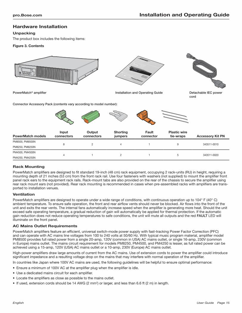
Hardware InstallationUnpacking
The product box includes the following items:
Figure 3. Contents
PowerMatch® amplifier Installation and Operating Guide Detachable IEC power cord
Connector Accessory Pack (contents vary according to model number):
PowerMatch modelsInput
connectorsOutput
connectorsShorting jumpers
Fault connector
Plastic wire tie-wraps Accessory Kit PN
PM8500, PM8500N8 2 4 1 9 343511-0010
PM8250, PM8250N
PM4500, PM4500N4 1 2 1 5 343511-0020
PM4250, PM4250N
Rack Mounting
PowerMatch amplifiers are designed to fit standard 19-inch (48 cm) rack equipment, occupying 2 rack-units (RU) in height, requiring a mounting depth of 21 inches (53 cm) from the front rack rail. Use four fasteners with washers (not supplied) to mount the amplifier front panel rack ears to the equipment rack rails. Rack-mount tabs are also provided on the rear of the chassis to secure the amplifier using rear rack mount ears (not provided). Rear rack mounting is recommended in cases when pre-assembled racks with amplifiers are trans-ported to installation venues.
Ventilation
PowerMatch amplifiers are designed to operate under a wide range of conditions, with continuous operation up to 104° F (40° C) ambient temperature. To ensure safe operation, the front and rear airflow vents should never be blocked. Air flows into the front of the unit and exits the rear vents. The internal fans automatically increase speed when the amplifier is generating more heat. Should the unit exceed safe operating temperature, a gradual reduction of gain will automatically be applied for thermal protection. If the automatic gain reduction does not reduce operating temperatures to safe conditions, the unit will mute all outputs and the red FAULT LED will illuminate on the front panel.
AC Mains Outlet Requirements
PowerMatch amplifiers feature an efficient, universal switch-mode power supply with fast-tracking Power Factor Correction (PFC) and can operate with AC mains line voltages from 100 to 240 volts at 50/60 Hz. With typical music program material, amplifier model PM8500 provides full rated power from a single 20-amp, 120V (common in USA) AC mains outlet, or single 16-amp, 230V (common in Europe) mains outlet. The mains circuit requirement for models PM8250, PM4500, and PM4250 is lesser, as full rated power can be achieved using a 15-amp, 120V (USA) AC mains outlet or a 10-amp, 230V (Europe) AC mains outlet.
High-power amplifiers draw large amounts of current from the AC mains. Use of extension cords to power the amplifier could introduce significant impedance and a resulting voltage drop on the mains that may interfere with normal operation of the amplifier.
In countries like Japan where 100V AC mains are used, the following guidelines will be helpful to ensure optimal performance:
• Ensure a minimum of 100V AC at the amplifier plug when the amplifier is idle.• Use a dedicated mains circuit for each amplifier.• Locate the amplifiers as close as possible to the mains outlet.• If used, extension cords should be 14 AWG (2 mm2) or larger, and less than 6.6 ft (2 m) in length.

Page16 UserGuide English
Installation and Operating Guide pro.Bose.com
Making ConnectionsConnection and Configuration Steps
Use the following procedure when setting up a PowerMatch® amplifier for the first time.
1. Install any digital expansion cards (optional)
2. Mount the amplifier into the rack
3. Connect power cable and retaining clip
4. Turn on amplifier
5. Enable Standby Mode from the front panel of the amplifier (See page 30.)
6. Configure amplifier (use front panel or ControlSpace® Designer™ software)
7. Wire input connection from source device(s)
8. Wire output connectors to speakers
9. Disable Standby Mode
10. Connect Fault Notification Output to management system or device (optional)
11. Clear alarms (See page 31.)
12. Test system
Power (Mains) Connection
Power connection is made using the included IEC power cord. The amplifier also includes a retaining clip to help secure the power connection to the amplifier. To install, place the retaining clip toward the center of the amplifier, plug in the IEC power cord, then swing the retaining clip so it locks behind the IEC connector.
Figure 4. IEC Connector retaining clip in place.
Standby Mode
Enabling Standby Mode decouples the amplifier section from the loudspeaker output. In this state the product also consumes less power. Standby Mode can be entered manually from the front panel using the following steps:
MAIN MENU > UTILITY > STANDBY MODE > press ENTER STANDBY
While in Standby, front panel options and loudspeaker output configurations can be changed without directly affecting the loudspeaker load.
Standby Mode can be automatically entered and exited using the Auto-Standby/Auto-Wake function as a method to help reduce energy usage during times when audio is not required. Refer to the ControlSpace Designer Software Guide for details on this feature.
English UserGuide Page17
pro.Bose.com Installation and Operating Guide
Wiring Input Connectors
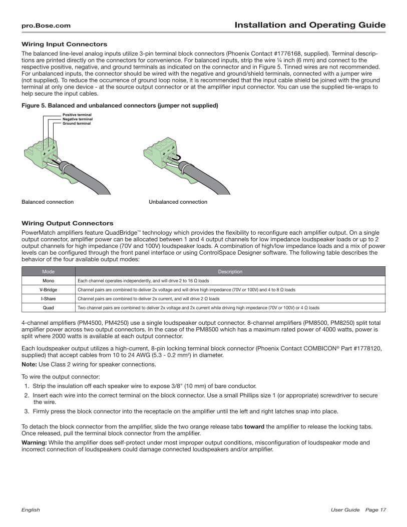
The balanced line-level analog inputs utilize 3-pin terminal block connectors (Phoenix Contact #1776168, supplied). Terminal descrip-tions are printed directly on the connectors for convenience. For balanced inputs, strip the wire ¼ inch (6 mm) and connect to the respective positive, negative, and ground terminals as indicated on the connector and in Figure 5. Tinned wires are not recommended. For unbalanced inputs, the connector should be wired with the negative and ground/shield terminals, connected with a jumper wire (not supplied). To reduce the occurrence of ground loop noise, it is recommended that the input cable shield be joined with the ground terminal at only one device - at the source output connector or at the amplifier input connector. You can use the supplied tie-wraps to help secure the input cables.
Figure 5. Balanced and unbalanced connectors (jumper not supplied)Positive terminalNegative terminalGround terminal
Balanced connection Unbalanced connection
Wiring Output Connectors
PowerMatch amplifiers feature QuadBridge™ technology which provides the flexibility to reconfigure each amplifier output. On a single output connector, amplifier power can be allocated between 1 and 4 output channels for low impedance loudspeaker loads or up to 2 output channels for high impedance (70V and 100V) loudspeaker loads. A combination of high/low impedance loads and a mix of power levels can be configured through the front panel interface or using ControlSpace Designer software. The following table describes the behavior of the four available output modes:
Mode Description
Mono Each channel operates independently, and will drive 2 to 16 Ω loads
V-Bridge Channel pairs are combined to deliver 2x voltage and will drive high impedance (70V or 100V) and 4 to 8 Ω loads
I-Share Channel pairs are combined to deliver 2x current, and will drive 2 Ω loads
Quad Two channel pairs are combined to deliver 2x voltage and 2x current while driving high impedance (70V or 100V) or 4 Ω loads
4-channel amplifiers (PM4500, PM4250) use a single loudspeaker output connector. 8-channel amplifiers (PM8500, PM8250) split total amplifier power across two output connectors. In the case of the PM8500 which has a maximum rated power of 4000 watts, power is split where 2000 watts is available at each output connector.
Each loudspeaker output utilizes a high-current, 8-pin locking terminal block connector (Phoenix Contact COMBICON® Part #1778120, supplied) that accept cables from 10 to 24 AWG (5.3 - 0.2 mm2) in diameter.
Note: Use Class 2 wiring for speaker connections.
To wire the output connector:
1. Strip the insulation off each speaker wire to expose 3/8" (10 mm) of bare conductor.
2. Insert each wire into the correct terminal on the block connector. Use a small Phillips size 1 (or appropriate) screwdriver to secure the wire.
3. Firmly press the block connector into the receptacle on the amplifier until the left and right latches snap into place.
To detach the block connector from the amplifier, slide the two orange release tabs toward the amplifier to release the locking tabs. Once released, pull the terminal block connector from the amplifier.
Warning: While the amplifier does self-protect under most improper output conditions, misconfiguration of loudspeaker mode and incorrect connection of loudspeakers could damage connected loudspeakers and/or amplifier.
Page18 UserGuide English
Installation and Operating Guide pro.Bose.com
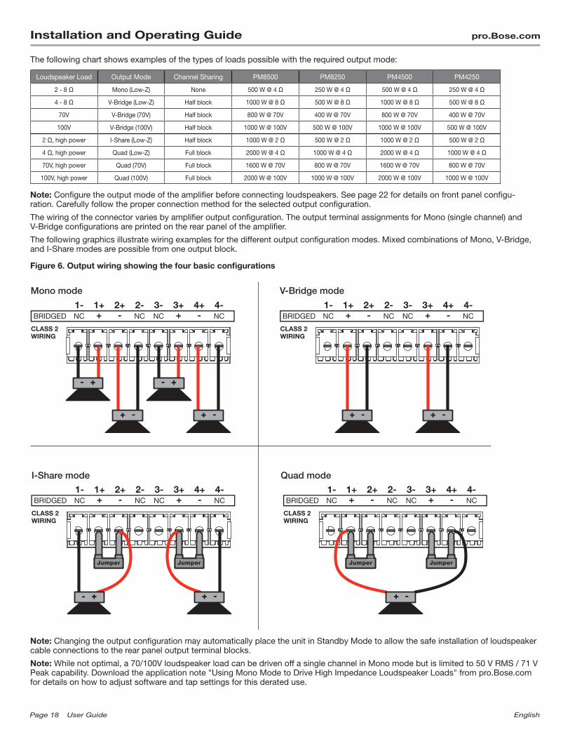
The following chart shows examples of the types of loads possible with the required output mode:
Loudspeaker Load Output Mode Channel Sharing PM8500 PM8250 PM4500 PM4250
2 - 8 Ω Mono (Low-Z) None 500 W @ 4 Ω 250 W @ 4 Ω 500 W @ 4 Ω 250 W @ 4 Ω
4 - 8 Ω V-Bridge (Low-Z) Half block 1000 W @ 8 Ω 500 W @ 8 Ω 1000 W @ 8 Ω 500 W @ 8 Ω
70V V-Bridge (70V) Half block 800 W @ 70V 400 W @ 70V 800 W @ 70V 400 W @ 70V
100V V-Bridge (100V) Half block 1000 W @ 100V 500 W @ 100V 1000 W @ 100V 500 W @ 100V
2 Ω, high power I-Share (Low-Z) Half block 1000 W @ 2 Ω 500 W @ 2 Ω 1000 W @ 2 Ω 500 W @ 2 Ω
4 Ω, high power Quad (Low-Z) Full block 2000 W @ 4 Ω 1000 W @ 4 Ω 2000 W @ 4 Ω 1000 W @ 4 Ω
70V, high power Quad (70V) Full block 1600 W @ 70V 800 W @ 70V 1600 W @ 70V 800 W @ 70V
100V, high power Quad (100V) Full block 2000 W @ 100V 1000 W @ 100V 2000 W @ 100V 1000 W @ 100V
Note: Configure the output mode of the amplifier before connecting loudspeakers. See page 22 for details on front panel configu-ration. Carefully follow the proper connection method for the selected output configuration.
The wiring of the connector varies by amplifier output configuration. The output terminal assignments for Mono (single channel) and V-Bridge configurations are printed on the rear panel of the amplifier.
The following graphics illustrate wiring examples for the different output configuration modes. Mixed combinations of Mono, V-Bridge, and I-Share modes are possible from one output block.
Figure 6. Output wiring showing the four basic configurations
Mono mode V-Bridge mode
I-Share mode Quad mode
Note: Changing the output configuration may automatically place the unit in Standby Mode to allow the safe installation of loudspeaker cable connections to the rear panel output terminal blocks.
Note: While not optimal, a 70/100V loudspeaker load can be driven off a single channel in Mono mode but is limited to 50 V RMS / 71 V Peak capability. Download the application note "Using Mono Mode to Drive High Impedance Loudspeaker Loads" from pro.Bose.com for details on how to adjust software and tap settings for this derated use.

English UserGuide Page19
pro.Bose.com Installation and Operating Guide
Fault Notification Output
Each PowerMatch amplifier features a hardware fault notification circuit. This circuit drives a normally open or normally closed contact closure (1A, 30 VDC maximum). The fault output, using the orange-colored 3-pin terminal block (Phoenix Contact #1976010, supplied), is intended to provide an external connection to a remote system monitor for fault notification purposes. Terminal assignments are printed directly on the connector as shown in Figure 7. See "About the Alarm Log and Fault Indicator" on page 38 for details on trapped faults and how to filter reported faults.
Figure 7. Fault Notification output connector
Normally closedCommonNormally open
Serial over Ethernet
Network version amplifiers can leverage the Ethernet connector to communicate serial data with control systems and devices. Commands are available to read and set Standby Mode status, and to read the output configuration. For interfacing with third party control systems, the amplifier is also able to read and set the amplifier to broadcast alarms, fault events, and changes to the Fault Output state when they occur.
A full listing of the available protocol can be found in the PDF document "ControlSpace Serial Control Protocol" on pro.Bose.com.

Page20 UserGuide English
Installation and Operating Guide pro.Bose.com
Setup and ConfigurationFigure 8 shows the basic signal flow and available DSP functions available to manipulate each individual input channel.
Some functions and advanced parameters can only be modified using ControlSpace® Designer™ software. See "Interface Comparison Table" on page 40 to view configurations required to access functions and features.
Figure 8. Simplified DSP block diagram (8-channel diagram shown; 4-channel models are similar)
Analog In
In A
Analog In
In B
Analog In
In C
Analog In
In D
Analog In
In E
Analog In
In F
Analog In
In G
Analog In
In H
Amp Output
Out 1
Amp Output
Out 2
Amp Output
Out 3
Amp Output
Out 4
Amp Output
Out 5
Amp Output
Out 6
Amp Output
Out 7
Amp Output
Out 8
Signal Generator
PEQ-5band
PEQ-5band
PEQ-5band
PEQ-5band
PEQ-5band
PEQ-5band
PEQ-5band
PEQ-5band
Array EQ MatrixA 1
Array EQ
Array EQ
Array EQ
Array EQ
Array EQ
Array EQ
Array EQ
Band Pass
Band Pass
Band Pass
Band Pass
Band Pass
Band Pass
Band Pass
Band Pass
SpeakerPEQ
SpeakerPEQ
SpeakerPEQ
SpeakerPEQ
SpeakerPEQ
SpeakerPEQ
SpeakerPEQ
SpeakerPEQ
Delay
Delay
Delay
Delay
Delay
Delay
Delay
Delay
Limiter
Limiter
Limiter
Limiter
Limiter
Limiter
Limiter
Limiter
B 2
C 3
D 4
E 5
F 6
G 7
H 8
Signal Generator
Configuration Methods
There are three methods to configure a PowerMatch amplifier for use. The table below shows those methods and describes function-ality differences between the methods.
Method of Configuration Use Case
1. Local front panel Fast, easy access to status, basic loudspeaker processing and control options.
2. USB connection to ControlSpace Designer software • Full-featured control and visibility over all DSP functions. • Graphical tools available to help create EQs for 3rd party loudspeakers, real time
display and monitoring. • Multiple network version amplifiers can be configured and monitored from a single
PC using an RJ45 Ethernet connection.
3. RJ45 connection to ControlSpace Designer software (network versions only)
English UserGuide Page21
pro.Bose.com Installation and Operating Guide
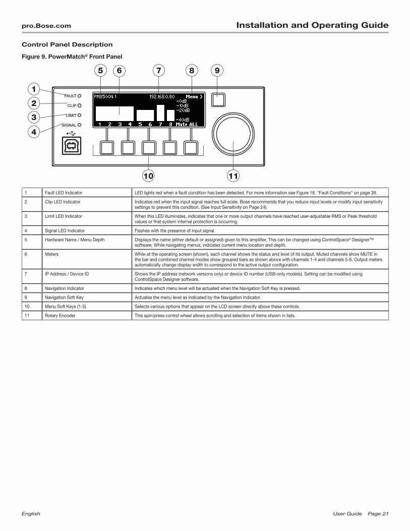
Control Panel Description
Figure 9. PowerMatch® Front Panel
1 Fault LED Indicator LED lights red when a fault condition has been detected. For more information see Figure 18, "Fault Conditions" on page 38.
2 Clip LED Indicator Indicates red when the input signal reaches full scale. Bose recommends that you reduce input levels or modify input sensitivity settings to prevent this condition. (See Input Sensitivity on Page 24).
3 Limit LED Indicator When this LED illuminates, indicates that one or more output channels have reached user-adjustable RMS or Peak threshold values or that system internal protection is occurring.
4 Signal LED Indicator Flashes with the presence of input signal.
5 Hardware Name / Menu Depth Displays the name (either default or assigned) given to this amplifier. This can be changed using ControlSpace® Designer™ software. While navigating menus, indicates current menu location and depth.
6 Meters While at the operating screen (shown), each channel shows the status and level of its output. Muted channels show MUTE in the bar and combined channel modes show grouped bars as shown above with channels 1-4 and channels 5-6. Output meters automatically change display width to correspond to the active output configuration.
7 IP Address / Device ID Shows the IP address (network versions only) or device ID number (USB-only models). Setting can be modified using ControlSpace Designer software.
8 Navigation Indicator Indicates which menu level will be actuated when the Navigation Soft Key is pressed.
9 Navigation Soft Key Actuates the menu level as indicated by the Navigation Indicator.
10 Menu Soft Keys (1-5) Selects various options that appear on the LCD screen directly above these controls.
11 Rotary Encoder This spin/press control wheel allows scrolling and selection of items shown in lists.
3
5 6 7 8 9
1110
1
2
4
Page22 UserGuide English
Installation and Operating Guide pro.Bose.com
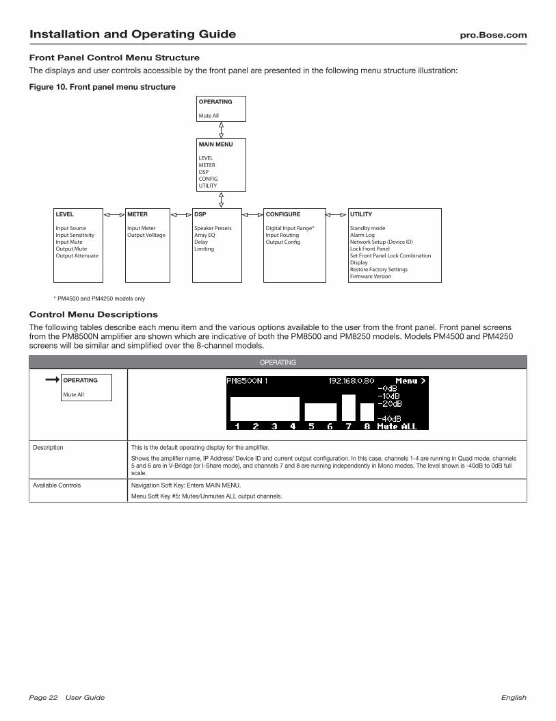
Front Panel Control Menu Structure
The displays and user controls accessible by the front panel are presented in the following menu structure illustration:
Figure 10. Front panel menu structure
OPERATING
Mute All
MAIN MENU
LEVELMETERDSPCONFIGUTILITY
DSP
Speaker PresetsArray EQDelayLimiting
LEVEL
Input SourceInput SensitivityInput MuteOutput MuteOutput Attenuate
METER
Input MeterOutput Volltage
CONFIGURE UTILITY
Standby modeAlarm LogNetwork Setup (Device ID)Lock Front PanelSet Front Panel Lock CombinationDisplayRestore Factory SettingsFirmware Version
* PM4500 and PM4250 models only
Control Menu Descriptions
The following tables describe each menu item and the various options available to the user from the front panel. Front panel screens from the PM8500N amplifier are shown which are indicative of both the PM8500 and PM8250 models. Models PM4500 and PM4250 screens will be similar and simplified over the 8-channel models.
OPERATING
OPERATING
Mute All
Description This is the default operating display for the amplifier.
Shows the amplifier name, IP Address/ Device ID and current output configuration. In this case, channels 1-4 are running in Quad mode, channels 5 and 6 are in V-Bridge (or I-Share mode), and channels 7 and 8 are running independently in Mono modes. The level shown is -40dB to 0dB full scale.
Available Controls Navigation Soft Key: Enters MAIN MENU.
Menu Soft Key #5: Mutes/Unmutes ALL output channels.
English UserGuide Page23
pro.Bose.com Installation and Operating Guide
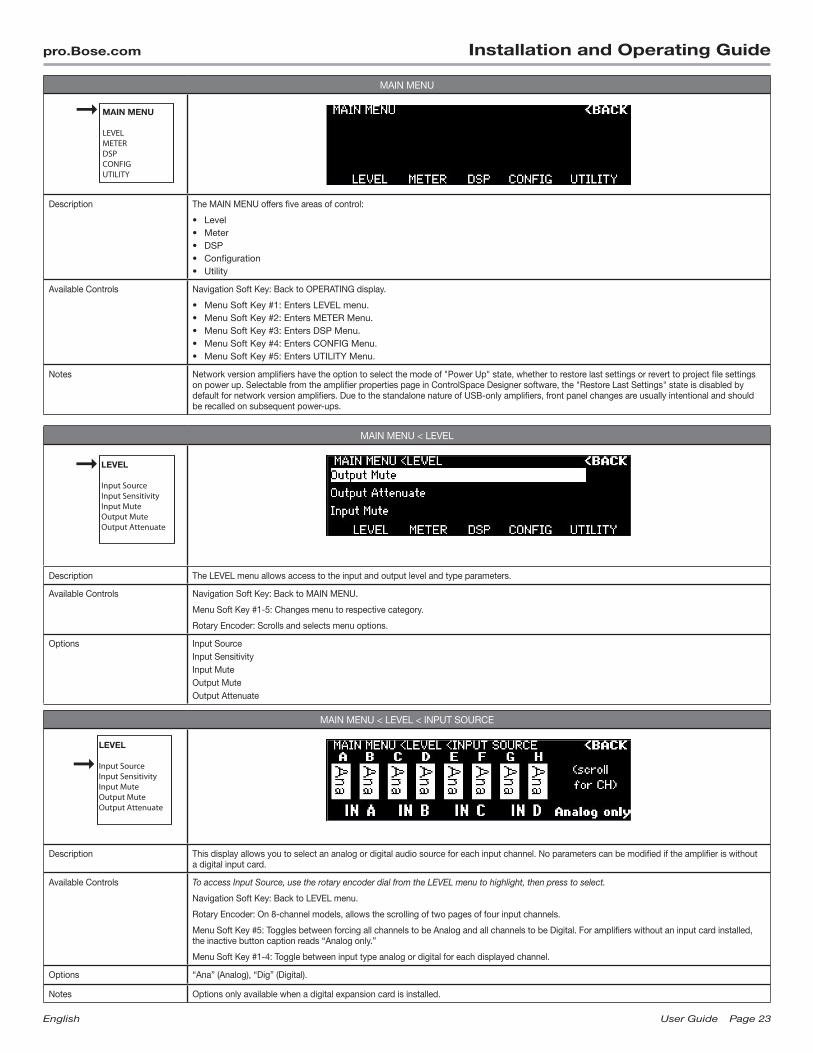
MAIN MENU
MAIN MENU
LEVELMETERDSPCONFIGUTILITY
Description The MAIN MENU offers five areas of control:
• Level• Meter• DSP• Configuration• Utility
Available Controls Navigation Soft Key: Back to OPERATING display.
• Menu Soft Key #1: Enters LEVEL menu.• Menu Soft Key #2: Enters METER Menu.• Menu Soft Key #3: Enters DSP Menu.• Menu Soft Key #4: Enters CONFIG Menu.• Menu Soft Key #5: Enters UTILITY Menu.
Notes Network version amplifiers have the option to select the mode of "Power Up" state, whether to restore last settings or revert to project file settings on power up. Selectable from the amplifier properties page in ControlSpace Designer software, the "Restore Last Settings" state is disabled by default for network version amplifiers. Due to the standalone nature of USB-only amplifiers, front panel changes are usually intentional and should be recalled on subsequent power-ups.
MAIN MENU < LEVEL
LEVEL
Input SourceInput SensitivityInput MuteOutput MuteOutput Attenuate
Description The LEVEL menu allows access to the input and output level and type parameters.
Available Controls Navigation Soft Key: Back to MAIN MENU.
Menu Soft Key #1-5: Changes menu to respective category.
Rotary Encoder: Scrolls and selects menu options.
Options Input SourceInput SensitivityInput Mute Output Mute Output Attenuate
MAIN MENU < LEVEL < INPUT SOURCE
LEVEL
Input SourceInput SensitivityInput MuteOutput MuteOutput Attenuate
Description This display allows you to select an analog or digital audio source for each input channel. No parameters can be modified if the amplifier is without a digital input card.
Available Controls To access Input Source, use the rotary encoder dial from the LEVEL menu to highlight, then press to select.
Navigation Soft Key: Back to LEVEL menu.
Rotary Encoder: On 8-channel models, allows the scrolling of two pages of four input channels.
Menu Soft Key #5: Toggles between forcing all channels to be Analog and all channels to be Digital. For amplifiers without an input card installed, the inactive button caption reads “Analog only.”
Menu Soft Key #1-4: Toggle between input type analog or digital for each displayed channel.
Options “Ana” (Analog), “Dig” (Digital).
Notes Options only available when a digital expansion card is installed.

Page24 UserGuide English
Installation and Operating Guide pro.Bose.com
MAIN MENU < LEVEL < INPUT SENS
LEVEL
Input SourceInput SensitivityInput MuteOutput MuteOutput Attenuate
Description This display allows you to appropriately match each configured input channel to the incoming signal. This per channel setting corresponds to the level that will create rated power out of the amplifier, with all other gains through the DSP signal processing chain set to 0 dB (unity gain). For best noise performance use the highest setting you can, keeping peaks of the input signal as close to the sensitivity level as you can without exceeding it.
Real-time output is displayed and affected by changing the sensitivity level.
Available Controls To access Input Sensitivity, use the rotary encoder dial from the LEVEL menu to highlight, then press to select.
Navigation Soft Key: Back to LEVEL menu.
Menu Soft Key #5: Enables the scrolling of four pages of two input channels using the rotary encoder.
Menu Soft Key #1 and #3: Enables the respective input channel to be selected. Use the rotary encoder to select sensitivity values in dBu.
Options +0.0 dBu, +4.0dBu, +12dBu, +24dBu
MAIN MENU < LEVEL < INPUT MUTE
LEVEL
Input SourceInput SensitivityInput MuteOutput MuteOutput Attenuate
Description This display allows you to mute each input channel.
Available Controls To access Input Mute, use the rotary encoder dial from the LEVEL menu to highlight, then press to select.
Navigation Soft Key: Back to LEVEL menu.
Rotary Encoder: Continuously scrolls through two input channel pages, allowing users to access Input A-D, and on 8-channel models, Input E-H.
Menu Soft Key #1-4: Toggles the mute state for each channel listed above each button.
Menu Soft Key #5: Enables/disables muting of all channels.
Options Mute enabled/disabled per channel.Mute ALL enabled/disabled for all channels.
Notes All input channels can also be muted from the MAIN MENU < METER < INPUT display.
MAIN MENU < LEVEL < OUTPUT MUTE
LEVEL
Input SourceInput SensitivityInput MuteOutput MuteOutput Attenuate
Description This display allows each configured output channel to be muted. For channels set to output modes other than Mono, as in the case shown with channels 1-4 above, muting control is bound by the configured groupings.
Available Controls To access Output Mute, use the rotary encoder dial from the LEVEL menu to highlight, then press to select.
Navigation Soft Key: Back to LEVEL MENU.
Rotary Encoder: Scrolls through output channels as displayed under the eight indicator boxes (8-channel models only).
Menu Soft Key #1-4: Toggles the mute state for each channel listed above each button. Note that some keys may not have channels listed.
Menu Soft Key #5: Enables/disables muting of all channels.
Options Mute enabled/disabled per channel.
Mute ALL enabled/disabled for all channels.
Notes Output channels can also be (all) muted from the MAIN MENU and MAIN MENU < METER < OUTPUT VOLTS screens.
English UserGuide Page25
pro.Bose.com Installation and Operating Guide
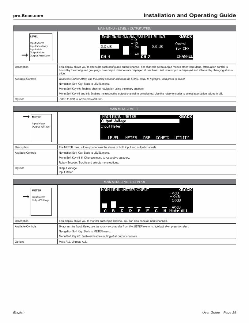
MAIN MENU < LEVEL < OUTPUT ATTEN
LEVEL
Input SourceInput SensitivityInput MuteOutput MuteOutput Attenuate
Description This display allows you to attenuate each configured output channel. For channels set to output modes other than Mono, attenuation control is bound by the configured groupings. Two output channels are displayed at one time. Real time output is displayed and affected by changing attenu-ation.
Available Controls To access Output Atten, use the rotary encoder dial from the LEVEL menu to highlight, then press to select.
Navigation Soft Key: Back to LEVEL menu.
Menu Soft Key #5: Enables channel navigation using the rotary encoder.
Menu Soft Key #1 and #3: Enables the respective output channel to be selected. Use the rotary encoder to select attenuation values in dB.
Options -60dB to 0dB in increments of 0.5dB.
MAIN MENU < METER
METER
Input MeterOutput Volltage
Description The METER menu allows you to view the status of both input and output channels.
Available Controls Navigation Soft Key: Back to LEVEL menu.
Menu Soft Key #1-5: Changes menu to respective category.
Rotary Encoder: Scrolls and selects menu options.
Options Output VoltageInput Meter
MAIN MENU < METER < INPUT
METER
Input MeterOutput Volltage
Description This display allows you to monitor each input channel. You can also mute all input channels.
Available Controls To access the Input Meter, use the rotary encoder dial from the METER menu to highlight, then press to select.
Navigation Soft Key: Back to METER menu.
Menu Soft Key #5: Enables/disables muting of all output channels.
Options Mute ALL, Unmute ALL.
Page26 UserGuide English
Installation and Operating Guide pro.Bose.com
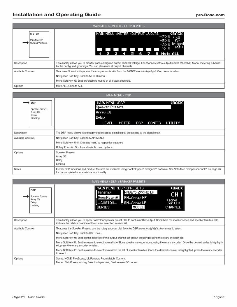
MAIN MENU < METER < OUTPUT VOLTS
METER
Input MeterOutput Volltage
Description This display allows you to monitor each configured output channel voltage. For channels set to output modes other than Mono, metering is bound by the configured groupings. You can also mute all output channels.
Available Controls To access Output Voltage, use the rotary encoder dial from the METER menu to highlight, then press to select.
Navigation Soft Key: Back to METER menu.
Menu Soft Key #5: Enables/disables muting of all output channels.
Options Mute ALL, Unmute ALL.
MAIN MENU < DSP
DSP
Speaker PresetsArray EQDelayLimiting
Description The DSP menu allows you to apply sophisticated digital signal processing to the signal chain.
Available Controls Navigation Soft Key: Back to MAIN MENU.
Menu Soft Key #1-5: Changes menu to respective category.
Rotary Encoder: Scrolls and selects menu options.
Options Speaker PresetsArray EQDelayLimiting
Notes Further DSP functions and product features are available using ControlSpace® Designer™ software. See “Interface Comparison Table” on page 26 for the complete list of available functionality.
MAIN MENU < DSP < SPEAKER PRESETS
DSP
Speaker PresetsArray EQDelayLimiting
Description This display allows you to apply Bose® loudspeaker preset EQs to each amplifier output. Scroll bars for speaker series and speaker families help indicate the relative position of the current selection in each list.
Available Controls To access the Speaker Presets, use the rotary encoder dial from the DSP menu to highlight, then press to select.
Navigation Soft Key: Back to DSP menu.
Menu Soft Key #5: Enables the selection of the output channel (or output groupings) using the rotary encoder dial.
Menu Soft Key #1: Enables users to select from a list of Bose speaker series, or none, using the rotary encoder. Once the desired series is highlight-ed, press the rotary encoder to select.
Menu Soft Key #3: Enables users to select from within the list of speaker families. Once the desired speaker is highlighted, press the rotary encoder to select.
Options Series: NONE, FreeSpace, LT, Panaray, RoomMatch, Custom.Model: Flat, Corresponding Bose loudspeakers, Custom user EQ curves.
English UserGuide Page27
pro.Bose.com Installation and Operating Guide
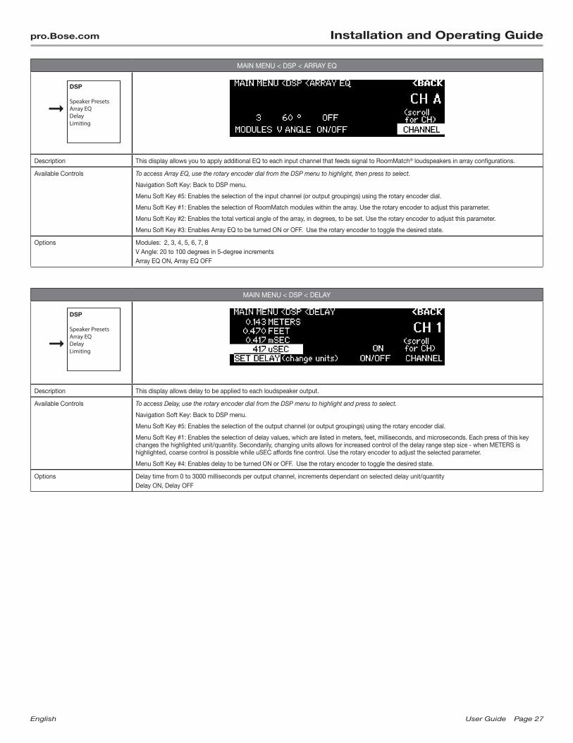
MAIN MENU < DSP < ARRAY EQ
DSP
Speaker PresetsArray EQDelayLimiting
Description This display allows you to apply additional EQ to each input channel that feeds signal to RoomMatch® loudspeakers in array configurations.
Available Controls To access Array EQ, use the rotary encoder dial from the DSP menu to highlight, then press to select.
Navigation Soft Key: Back to DSP menu.
Menu Soft Key #5: Enables the selection of the input channel (or output groupings) using the rotary encoder dial.
Menu Soft Key #1: Enables the selection of RoomMatch modules within the array. Use the rotary encoder to adjust this parameter.
Menu Soft Key #2: Enables the total vertical angle of the array, in degrees, to be set. Use the rotary encoder to adjust this parameter.
Menu Soft Key #3: Enables Array EQ to be turned ON or OFF. Use the rotary encoder to toggle the desired state.
Options Modules: 2, 3, 4, 5, 6, 7, 8V Angle: 20 to 100 degrees in 5-degree incrementsArray EQ ON, Array EQ OFF
MAIN MENU < DSP < DELAY
DSP
Speaker PresetsArray EQDelayLimiting
Description This display allows delay to be applied to each loudspeaker output.
Available Controls To access Delay, use the rotary encoder dial from the DSP menu to highlight and press to select.
Navigation Soft Key: Back to DSP menu.
Menu Soft Key #5: Enables the selection of the output channel (or output groupings) using the rotary encoder dial.
Menu Soft Key #1: Enables the selection of delay values, which are listed in meters, feet, milliseconds, and microseconds. Each press of this key changes the highlighted unit/quantity. Secondarily, changing units allows for increased control of the delay range step size - when METERS is highlighted, coarse control is possible while uSEC affords fine control. Use the rotary encoder to adjust the selected parameter.
Menu Soft Key #4: Enables delay to be turned ON or OFF. Use the rotary encoder to toggle the desired state.
Options Delay time from 0 to 3000 milliseconds per output channel, increments dependant on selected delay unit/quantityDelay ON, Delay OFF

Page28 UserGuide English
Installation and Operating Guide pro.Bose.com
MAIN MENU < DSP < LIMITING
DSP
Speaker PresetsArray EQDelayLimiting
Description This display allows you to adjust limiting parameters that allow for loudspeaker driver protection for each output channel.
Available Controls To access Limiting, use the rotary encoder dial from the DSP menu to highlight, then press to select.
Navigation Soft Key: Back to DSP menu.
Menu Soft Key #5: Enables the selection of the output channel (or output groupings) using the rotary encoder dial.
Menu Soft Key #1: Enables the selection of a peak voltage value, which corresponds to the maximum voltage that may be applied to the driver without causing over-excursion. Use the rotary encoder to adjust the selected parameter.
Menu Soft Key #2: Enables the selection of an RMS voltage threshold value, which works in conjunction with the subsequent attack and release values. The RMS voltage setting corresponds to the long-term power handling capability of the loudspeaker. Use the rotary encoder to adjust the selected parameter.
Menu Soft Key #3: Enables the selection of attack time, in milliseconds, related to the RMS limiter. Use the rotary encoder to adjust the selected parameter.
Menu Soft Key #4: Enables the selection of release time, in milliseconds, related to the RMS limiter. Use the rotary encoder to adjust the selected parameter.
Options PEAK: 0.5 to 200 Volts (dependant on output mode), 0.5 V incrementsRMS: 0.5 to 100 Volts (dependant on output mode), 0.5 V incrementsATTACK: From 500 to 10,000 millisecondsRELEASE: From 500 to 10,000 milliseconds
Notes Values are automatically applied for Bose® loudspeakers set in MAIN MENU < DSP < SPEAKER PRESETS.For non-Bose loudspeakers, refer to manufacturer technical specifications for information to properly configure the limiter.See "Setting the Limiting Function for use with 3rd Party Loudspeakers" on page 34 for further details.
MAIN MENU < CONFIGURE
CONFIGURE
Description The CONFIGURE menu allows you to access the configuration of input and output signals for a particular system design.
Available Controls Navigation Soft Key: Return back to MAIN MENU.
Menu Soft Key #1-5: Changes menu to respective category.
Rotary Encoder: Scrolls and selects menu options.
Options Output ConfigInput Routing
MAIN MENU < CONFIGURE < DIGITAL INPUT RANGE
CONFIGURE
Description On 4-channel models (PM4500, PM4250), a group of channels from expansion cards card can be mapped to input channels A-D.
Available Controls "To access Digital Input Range, use the rotary encoder dial from the CONFIGURE menu to highlight, then press to select. Navigation Soft Key: Back to CONFIG menu. Menu Soft Key #1 and 2: Selects a range of digital input channels for access by the amplifier."
Options [1-4], [5-8]
Notes Amplifier models PM4500 and PM4250 are input channel limited to four analog and/or four digital channels. For additional flexibility, 8-channel feeds from the digital expansion slot have been grouped into 4-channel banks for selective use in installations with multiple 4-channel PowerMatch amplifiers.
English UserGuide Page29
pro.Bose.com Installation and Operating Guide
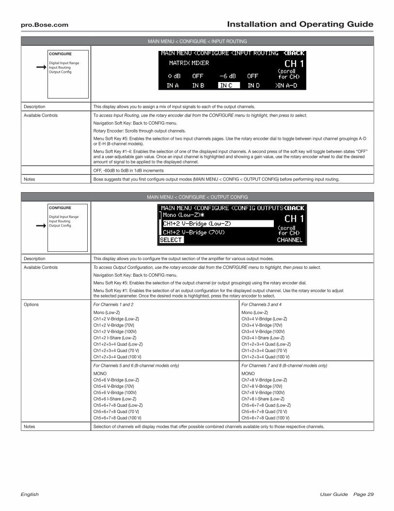
MAIN MENU < CONFIGURE < INPUT ROUTING
CONFIGURE
Description This display allows you to assign a mix of input signals to each of the output channels.
Available Controls To access Input Routing, use the rotary encoder dial from the CONFIGURE menu to highlight, then press to select.
Navigation Soft Key: Back to CONFIG menu.
Rotary Encoder: Scrolls through output channels.
Menu Soft Key #5: Enables the selection of two input channels pages. Use the rotary encoder dial to toggle between input channel groupings A-D or E-H (8-channel models).
Menu Soft Key #1-4: Enables the selection of one of the displayed input channels. A second press of the soft key will toggle between states “OFF” and a user-adjustable gain value. Once an input channel is highlighted and showing a gain value, use the rotary encoder wheel to dial the desired amount of signal to be applied to the displayed channel.
OFF, -60dB to 0dB in 1dB increments
Notes Bose suggests that you first configure output modes (MAIN MENU < CONFIG < OUTPUT CONFIG) before performing input routing.
MAIN MENU < CONFIGURE < OUTPUT CONFIG
CONFIGURE
Description This display allows you to configure the output section of the amplifier for various output modes.
Available Controls To access Output Configuration, use the rotary encoder dial from the CONFIGURE menu to highlight, then press to select.
Navigation Soft Key: Back to CONFIG menu.
Menu Soft Key #5: Enables the selection of the output channel (or output groupings) using the rotary encoder dial.
Menu Soft Key #1: Enables the selection of an output configuration for the displayed output channel. Use the rotary encoder to adjust the selected parameter. Once the desired mode is highlighted, press the rotary encoder to select.
Options For Channels 1 and 2
Mono (Low-Z)Ch1+2 V-Bridge (Low-Z)Ch1+2 V-Bridge (70V)Ch1+2 V-Bridge (100V)Ch1+2 I-Share (Low-Z)Ch1+2+3+4 Quad (Low-Z)Ch1+2+3+4 Quad (70 V)Ch1+2+3+4 Quad (100 V)
For Channels 3 and 4
Mono (Low-Z)Ch3+4 V-Bridge (Low-Z)Ch3+4 V-Bridge (70V)Ch3+4 V-Bridge (100V)Ch3+4 I-Share (Low-Z)Ch1+2+3+4 Quad (Low-Z)Ch1+2+3+4 Quad (70 V)Ch1+2+3+4 Quad (100 V)
For Channels 5 and 6 (8-channel models only)
MONOCh5+6 V-Bridge (Low-Z)Ch5+6 V-Bridge (70V)Ch5+6 V-Bridge (100V)Ch5+6 I-Share (Low-Z)Ch5+6+7+8 Quad (Low-Z)Ch5+6+7+8 Quad (70 V)Ch5+6+7+8 Quad (100 V)
For Channels 7 and 8 (8-channel models only)
MONOCh7+8 V-Bridge (Low-Z)Ch7+8 V-Bridge (70V)Ch7+8 V-Bridge (100V)Ch7+8 I-Share (Low-Z)Ch5+6+7+8 Quad (Low-Z)Ch5+6+7+8 Quad (70 V)Ch5+6+7+8 Quad (100 V)
Notes Selection of channels will display modes that offer possible combined channels available only to those respective channels.
Page30 UserGuide English
Installation and Operating Guide pro.Bose.com
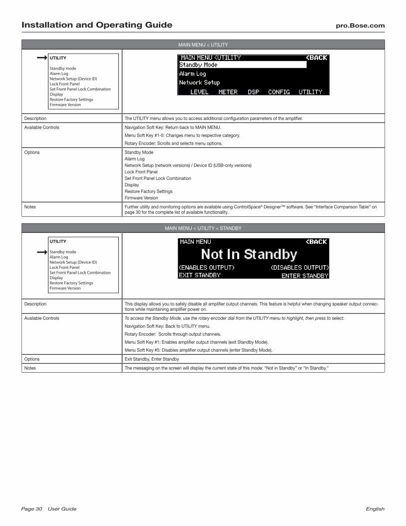
MAIN MENU < UTILITY
UTILITY
Standby modeAlarm LogNetwork Setup (Device ID)Lock Front PanelSet Front Panel Lock CombinationDisplayRestore Factory SettingsFirmware Version
Description The UTILITY menu allows you to access additional configuration parameters of the amplifier.
Available Controls Navigation Soft Key: Return back to MAIN MENU.
Menu Soft Key #1-5: Changes menu to respective category.
Rotary Encoder: Scrolls and selects menu options.
Options Standby ModeAlarm LogNetwork Setup (network versions) / Device ID (USB-only versions)Lock Front PanelSet Front Panel Lock CombinationDisplayRestore Factory SettingsFirmware Version
Notes Further utility and monitoring options are available using ControlSpace® Designer™ software. See “Interface Comparison Table” on page 30 for the complete list of available functionality.
MAIN MENU < UTILITY < STANDBY
UTILITY
Standby modeAlarm LogNetwork Setup (Device ID)Lock Front PanelSet Front Panel Lock CombinationDisplayRestore Factory SettingsFirmware Version
Description This display allows you to safely disable all amplifier output channels. This feature is helpful when changing speaker output connec-tions while maintaining amplifier power on.
Available Controls To access the Standby Mode, use the rotary encoder dial from the UTILITY menu to highlight, then press to select.
Navigation Soft Key: Back to UTILITY menu.
Rotary Encoder: Scrolls through output channels.
Menu Soft Key #1: Enables amplifier output channels (exit Standby Mode).
Menu Soft Key #5: Disables amplifier output channels (enter Standby Mode).
Options Exit Standby, Enter Standby
Notes The messaging on the screen will display the current state of this mode: “Not in Standby” or “In Standby.”
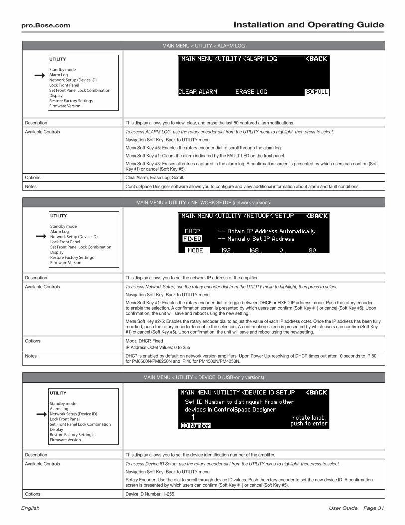
English UserGuide Page31
pro.Bose.com Installation and Operating Guide
MAIN MENU < UTILITY < ALARM LOG
UTILITY
Standby modeAlarm LogNetwork Setup (Device ID)Lock Front PanelSet Front Panel Lock CombinationDisplayRestore Factory SettingsFirmware Version
Description This display allows you to view, clear, and erase the last 50 captured alarm notifications.
Available Controls To access ALARM LOG, use the rotary encoder dial from the UTILITY menu to highlight, then press to select.
Navigation Soft Key: Back to UTILITY menu.
Menu Soft Key #5: Enables the rotary encoder dial to scroll through the alarm log.
Menu Soft Key #1: Clears the alarm indicated by the FAULT LED on the front panel.
Menu Soft Key #3: Erases all entries captured in the alarm log. A confirmation screen is presented by which users can confirm (Soft Key #1) or cancel (Soft Key #5).
Options Clear Alarm, Erase Log, Scroll.
Notes ControlSpace Designer software allows you to configure and view additional information about alarm and fault conditions.
MAIN MENU < UTILITY < NETWORK SETUP (network versions)
UTILITY
Standby modeAlarm LogNetwork Setup (Device ID)Lock Front PanelSet Front Panel Lock CombinationDisplayRestore Factory SettingsFirmware Version
Description This display allows you to set the network IP address of the amplifier.
Available Controls To access Network Setup, use the rotary encoder dial from the UTILITY menu to highlight, then press to select.
Navigation Soft Key: Back to UTILITY menu.
Menu Soft Key #1: Enables the rotary encoder dial to toggle between DHCP or FIXED IP address mode. Push the rotary encoder to enable the selection. A confirmation screen is presented by which users can confirm (Soft Key #1) or cancel (Soft Key #5). Upon confirmation, the unit will save and reboot using the new setting.
Menu Soft Key #2-5: Enables the rotary encoder dial to adjust the value of each IP address octet. Once the IP address has been fully modified, push the rotary encoder to enable the selection. A confirmation screen is presented by which users can confirm (Soft Key #1) or cancel (Soft Key #5). Upon confirmation, the unit will save and reboot using the new setting.
Options Mode: DHCP, FixedIP Address Octet Values: 0 to 255
Notes DHCP is enabled by default on network version amplifiers. Upon Power Up, resolving of DHCP times out after 10 seconds to IP:80 for PM8500N/PM8250N and IP:40 for PM4500N/PM4250N.
MAIN MENU < UTILITY < DEVICE ID (USB-only versions)
UTILITY
Standby modeAlarm LogNetwork Setup (Device ID)Lock Front PanelSet Front Panel Lock CombinationDisplayRestore Factory SettingsFirmware Version
Description This display allows you to set the device identification number of the amplifier.
Available Controls To access Device ID Setup, use the rotary encoder dial from the UTILITY menu to highlight, then press to select.
Navigation Soft Key: Back to UTILITY menu.
Rotary Encoder: Use the dial to scroll through device ID values. Push the rotary encoder to set the new device ID. A confirmation screen is presented by which users can confirm (Soft Key #1) or cancel (Soft Key #5).
Options Device ID Number: 1-255
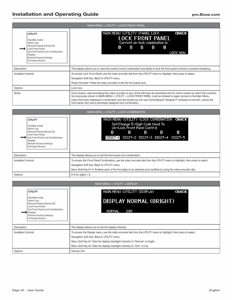
Page32 UserGuide English
Installation and Operating Guide pro.Bose.com
MAIN MENU < UTILITY < LOCK FRONT PANEL
UTILITY
Standby modeAlarm LogNetwork Setup (Device ID)Lock Front PanelSet Front Panel Lock CombinationDisplayRestore Factory SettingsFirmware Version
Description This display allows you to view the current unlock combination and ability to lock the front panel controls to prevent tampering.
Available Controls To access Lock Front Panel, use the rotary encoder dial from the UTILITY menu to highlight, then press to select.
Navigation Soft Key: Back to UTILITY menu.
Rotary Encoder: Press the rotary encoder to set the front panel lock.
Options Lock now
Notes Once locked, users accessing the rotary encoder or any of the soft keys are prompted with an unlock screen by which the combina-tion previously shown in MAIN MENU < UTILITY < LOCK FRONT PANEL must be entered to regain access to the Main Menu.Users that have misplaced a combination and are locked out can use ControlSpace® Designer™ software to connect, unlock the front panel, and view a previously assigned lock combination.
MAIN MENU < UTILITY < LOCK COMBINATION
UTILITY
Standby modeAlarm LogNetwork Setup (Device ID)Lock Front PanelSet Front Panel Lock CombinationDisplayRestore Factory SettingsFirmware Version
Description This display allows you to set the front panel lock combination.
Available Controls To access Set Front Panel Combination, use the rotary encoder dial from the UTILITY menu to highlight, then press to select.
Navigation Soft Key: Back to UTILITY menu.
Menu Soft Key #1-5: Enables each of the five digits to be selected and modified by using the rotary encoder dial.
Options 0–9 for digits 1–5.
MAIN MENU < UTILITY < DISPLAY
UTILITY
Standby modeAlarm LogNetwork Setup (Device ID)Lock Front PanelSet Front Panel Lock CombinationDisplayRestore Factory SettingsFirmware Version
Description This display allows you to set the display intensity.
Available Controls To access the Display menu, use the rotary encoder dial from the UTILITY menu to highlight, then press to select.
Navigation Soft Key: Back to UTILITY menu.
Menu Soft Key #1: Sets the display backlight intensity to “Normal” or bright.
Menu Soft Key #2: Sets the display backlight intensity to “Dim” or low.
Options Normal, Dim
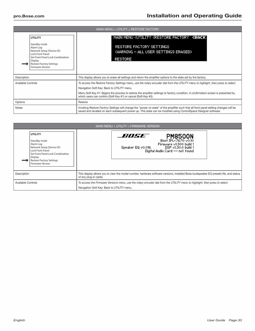
English UserGuide Page33
pro.Bose.com Installation and Operating Guide
MAIN MENU < UTILITY < RESTORE FACTORY
UTILITY
Standby modeAlarm LogNetwork Setup (Device ID)Lock Front PanelSet Front Panel Lock CombinationDisplayRestore Factory SettingsFirmware Version
Description This display allows you to erase all settings and return the amplifier options to the state set by the factory.
Available Controls To access the Restore Factory Settings menu, use the rotary encoder dial from the UTILITY menu to highlight, then press to select.
Navigation Soft Key: Back to UTILITY menu.
Menu Soft Key #1: Begins the process to restore the amplifier settings to factory condition. A confirmation screen is presented by which users can confirm (Soft Key #1) or cancel (Soft Key #5).
Options Restore
Notes Invoking Restore Factory Settings will change the "power on state" of the amplifier such that all front panel setting changes will be saved and recalled on each subsequent power up. This state can be modified using ControlSpace Designer software.
MAIN MENU < UTILITY < FIRMWARE VERSION
UTILITY
Standby modeAlarm LogNetwork Setup (Device ID)Lock Front PanelSet Front Panel Lock CombinationDisplayRestore Factory SettingsFirmware Version
Description This display allows you to view the model number, hardware software versions, installed Bose loudspeaker EQ presets file, and status of any plug-in cards.
Available Controls To access the Firmware Versions menu, use the rotary encoder dial from the UTILITY menu to highlight, then press to select.
Navigation Soft Key: Back to UTILITY menu.
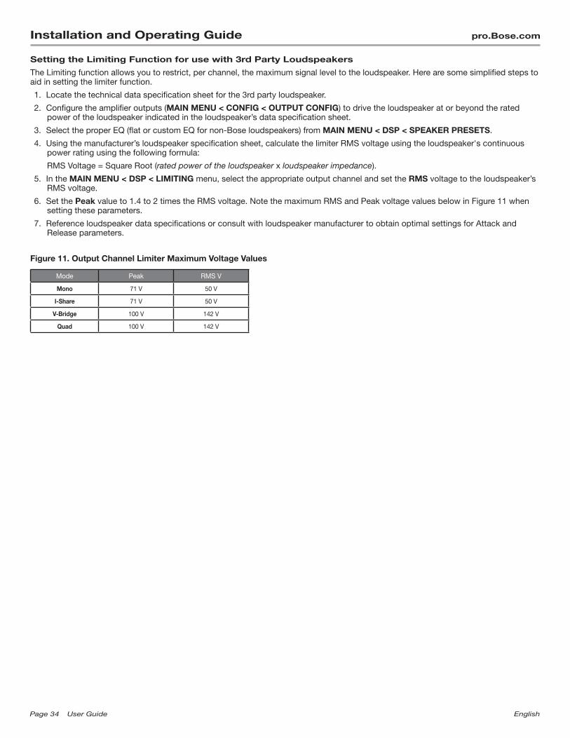
Page34 UserGuide English
Installation and Operating Guide pro.Bose.com
Setting the Limiting Function for use with 3rd Party Loudspeakers
The Limiting function allows you to restrict, per channel, the maximum signal level to the loudspeaker. Here are some simplified steps to aid in setting the limiter function.
1. Locate the technical data specification sheet for the 3rd party loudspeaker.
2. Configure the amplifier outputs (MAIN MENU < CONFIG < OUTPUT CONFIG) to drive the loudspeaker at or beyond the rated power of the loudspeaker indicated in the loudspeaker’s data specification sheet.
3. Select the proper EQ (flat or custom EQ for non-Bose loudspeakers) from MAIN MENU < DSP < SPEAKER PRESETS.
4. Using the manufacturer’s loudspeaker specification sheet, calculate the limiter RMS voltage using the loudspeaker's continuous power rating using the following formula:
RMS Voltage = Square Root (rated power of the loudspeaker x loudspeaker impedance).
5. In the MAIN MENU < DSP < LIMITING menu, select the appropriate output channel and set the RMS voltage to the loudspeaker’s RMS voltage.
6. Set the Peak value to 1.4 to 2 times the RMS voltage. Note the maximum RMS and Peak voltage values below in Figure 11 when setting these parameters.
7. Reference loudspeaker data specifications or consult with loudspeaker manufacturer to obtain optimal settings for Attack and Release parameters.
Figure 11. Output Channel Limiter Maximum Voltage Values
Mode Peak RMS V
Mono 71 V 50 V
I-Share 71 V 50 V
V-Bridge 100 V 142 V
Quad 100 V 142 V
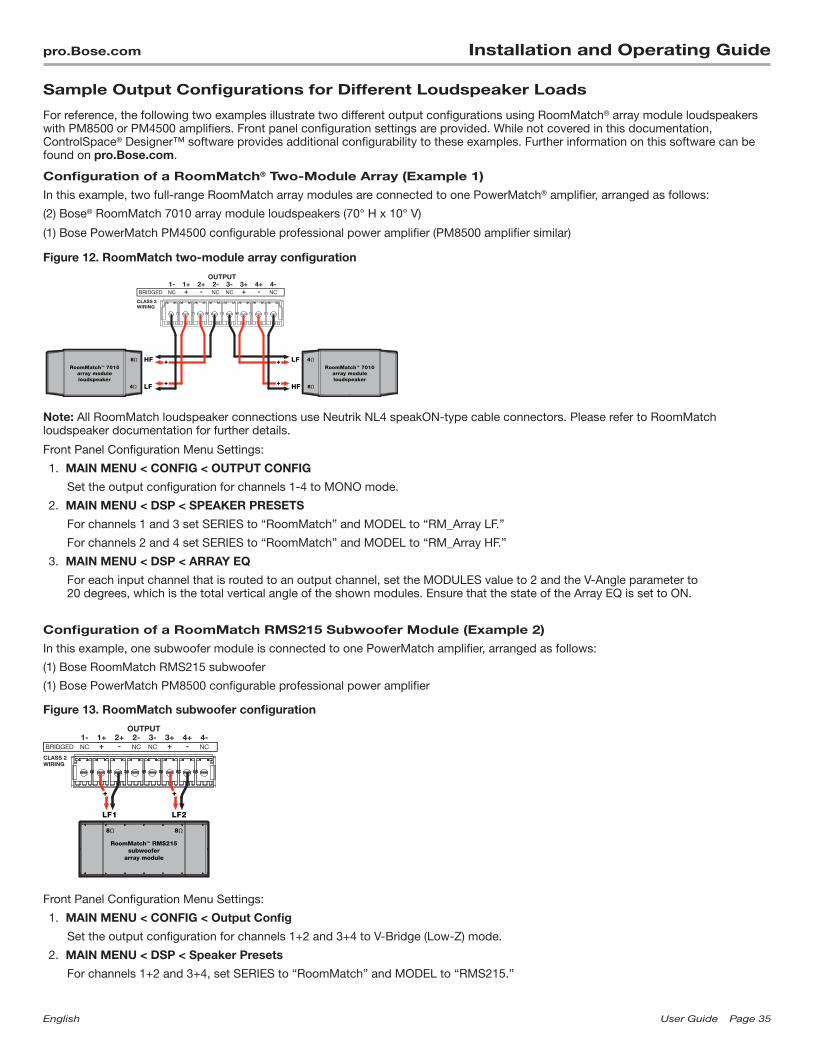
English UserGuide Page35
pro.Bose.com Installation and Operating Guide
Sample Output Configurations for Different Loudspeaker Loads
For reference, the following two examples illustrate two different output configurations using RoomMatch® array module loudspeakers with PM8500 or PM4500 amplifiers. Front panel configuration settings are provided. While not covered in this documentation, ControlSpace® Designer™ software provides additional configurability to these examples. Further information on this software can be found on pro.Bose.com.
Configuration of a RoomMatch® Two-Module Array (Example 1)
In this example, two full-range RoomMatch array modules are connected to one PowerMatch® amplifier, arranged as follows:
(2) Bose® RoomMatch 7010 array module loudspeakers (70° H x 10° V)
(1) Bose PowerMatch PM4500 configurable professional power amplifier (PM8500 amplifier similar)
Figure 12. RoomMatch two-module array configuration
Note: All RoomMatch loudspeaker connections use Neutrik NL4 speakON-type cable connectors. Please refer to RoomMatch loudspeaker documentation for further details.
Front Panel Configuration Menu Settings:
1. MAIN MENU < CONFIG < OUTPUT CONFIG
Set the output configuration for channels 1-4 to MONO mode.
2. MAIN MENU < DSP < SPEAKER PRESETS
For channels 1 and 3 set SERIES to “RoomMatch” and MODEL to “RM_Array LF.”
For channels 2 and 4 set SERIES to “RoomMatch” and MODEL to “RM_Array HF.”
3. MAIN MENU < DSP < ARRAY EQ
For each input channel that is routed to an output channel, set the MODULES value to 2 and the V-Angle parameter to 20 degrees, which is the total vertical angle of the shown modules. Ensure that the state of the Array EQ is set to ON.
Configuration of a RoomMatch RMS215 Subwoofer Module (Example 2)
In this example, one subwoofer module is connected to one PowerMatch amplifier, arranged as follows:
(1) Bose RoomMatch RMS215 subwoofer
(1) Bose PowerMatch PM8500 configurable professional power amplifier
Figure 13. RoomMatch subwoofer configuration
Front Panel Configuration Menu Settings:
1. MAIN MENU < CONFIG < Output Config
Set the output configuration for channels 1+2 and 3+4 to V-Bridge (Low-Z) mode.
2. MAIN MENU < DSP < Speaker Presets
For channels 1+2 and 3+4, set SERIES to “RoomMatch” and MODEL to “RMS215.”
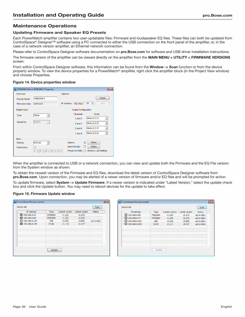
Page36 UserGuide English
Installation and Operating Guide pro.Bose.com
Maintenance OperationsUpdating Firmware and Speaker EQ Presets
Each PowerMatch amplifier contains two user-updatable files: Firmware and loudspeaker EQ files. These files can both be updated from ControlSpace® Designer™ software using a PC connected to either the USB connection on the front panel of the amplifier, or, in the case of a network version amplifier, an Ethernet network connection.
Please refer to ControlSpace Designer software documentation on pro.Bose.com for software and USB driver installation instructions.
The firmware version of the amplifier can be viewed directly on the amplifier from the MAIN MENU < UTILITY < FIRMWARE VERSIONS screen.
From within ControlSpace Designer software, this information can be found from the Window -> Scan function or from the device property window. To view the device properties for a PowerMatch® amplifier, right click the amplifier block (in the Project View window) and choose Properties.
Figure 14. Device properties window
When the amplifier is connected to USB or a network connection, you can view and update both the Firmware and the EQ File version from the System window as shown.
To obtain the newest version of the Firmware and EQ files, download the latest version of ControlSpace Designer software from pro.Bose.com. Upon connection, you may be alerted of a newer version of firmware and/or EQ files and will be prompted for action.
To update firmware, select System -> Update Firmware. If a newer version is indicated under “Latest Version,” select the update check box and click the Update button. You may need to reboot devices for the update to take effect.
Figure 15. Firmware Update window

English UserGuide Page37
pro.Bose.com Installation and Operating Guide
To update the amplifier’s EQ file, select System -> Update EQ file. Same as the process to update firmware, if a newer version is available from the drop-down list under “Latest Version,” select the update check box and click the Update button.
Figure 16. EQ Update window
Note: Between timed releases of ControlSpace® Designer™ software, PowerMatch® firmware updates and loudspeaker EQ files may become available. Check pro.Bose.com for updates and instructions on how to load and apply these files.
Saving and Recalling Amplifier Settings (USB-only version amplifiers)
You can save amplifier settings using a PC, USB connection, and ControlSpace Designer software. This may be useful for archiving settings made on the front panel after installation. You may also find it useful to copy settings from one PowerMatch amplifier to other PowerMatch amplifiers.
To save front panel settings:
1. Install ControlSpace Designer software on a compatible PC.
2. Connect the PC to the amplifier using USB.
3. Start ControlSpace Designer.
4. The amplifier should automatically connect and populate into the Project Window.
5. Save the Project File by selecting File -> Save As… from the menu bar.
To replace front panel settings with a previously saved filed:
1. Start ControlSpace Designer.
2. Open the previously saved Project File by selecting File -> Open from the menu bar.
3. Connect the PC to the amplifier using USB.
4. Click the YES button when presented with a dialog box asking, “Go Online via USB?”
5. Click “Send to Device” in the Settings Transfer window (Figure 17) to push the settings to the connected amplifier.
Figure 17. Settings Transfer window
Saving and Recalling Amplifier Settings (network version amplifiers)
With any network version amplifier, you can save and update device settings within a networked system with one or more amplifiers. This process is outside the scope of this guide. Refer to the ControlSpace Designer software documentation for details.
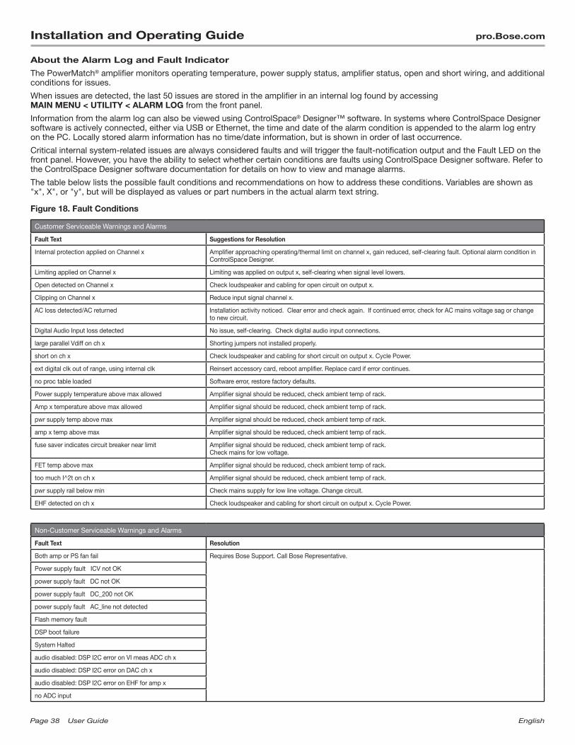
Page38 UserGuide English
Installation and Operating Guide pro.Bose.com
About the Alarm Log and Fault Indicator
The PowerMatch® amplifier monitors operating temperature, power supply status, amplifier status, open and short wiring, and additional conditions for issues.
When issues are detected, the last 50 issues are stored in the amplifier in an internal log found by accessing MAIN MENU < UTILITY < ALARM LOG from the front panel.
Information from the alarm log can also be viewed using ControlSpace® Designer™ software. In systems where ControlSpace Designer software is actively connected, either via USB or Ethernet, the time and date of the alarm condition is appended to the alarm log entry on the PC. Locally stored alarm information has no time/date information, but is shown in order of last occurrence.
Critical internal system-related issues are always considered faults and will trigger the fault-notification output and the Fault LED on the front panel. However, you have the ability to select whether certain conditions are faults using ControlSpace Designer software. Refer to the ControlSpace Designer software documentation for details on how to view and manage alarms.
The table below lists the possible fault conditions and recommendations on how to address these conditions. Variables are shown as "x", X", or "y", but will be displayed as values or part numbers in the actual alarm text string.
Figure 18. Fault Conditions
Customer Serviceable Warnings and Alarms
Fault Text Suggestions for Resolution
Internal protection applied on Channel x Amplifier approaching operating/thermal limit on channel x, gain reduced, self-clearing fault. Optional alarm condition in ControlSpace Designer.
Limiting applied on Channel x Limiting was applied on output x, self-clearing when signal level lowers.
Open detected on Channel x Check loudspeaker and cabling for open circuit on output x.
Clipping on Channel x Reduce input signal channel x.
AC loss detected/AC returned Installation activity noticed. Clear error and check again. If continued error, check for AC mains voltage sag or change to new circuit.
Digital Audio Input loss detected No issue, self-clearing. Check digital audio input connections.
large parallel Vdiff on ch x Shorting jumpers not installed properly.
short on ch x Check loudspeaker and cabling for short circuit on output x. Cycle Power.
ext digital clk out of range, using internal clk Reinsert accessory card, reboot amplifier. Replace card if error continues.
no proc table loaded Software error, restore factory defaults.
Power supply temperature above max allowed Amplifier signal should be reduced, check ambient temp of rack.
Amp x temperature above max allowed Amplifier signal should be reduced, check ambient temp of rack.
pwr supply temp above max Amplifier signal should be reduced, check ambient temp of rack.
amp x temp above max Amplifier signal should be reduced, check ambient temp of rack.
fuse saver indicates circuit breaker near limit Amplifier signal should be reduced, check ambient temp of rack. Check mains for low voltage.
FET temp above max Amplifier signal should be reduced, check ambient temp of rack.
too much I^2t on ch x Amplifier signal should be reduced, check ambient temp of rack.
pwr supply rail below min Check mains supply for low line voltage. Change circuit.
EHF detected on ch x Check loudspeaker and cabling for short circuit on output x. Cycle Power.
Non-Customer Serviceable Warnings and Alarms
Fault Text Resolution
Both amp or PS fan fail Requires Bose Support. Call Bose Representative.
Power supply fault ICV not OK
power supply fault DC not OK
power supply fault DC_200 not OK
power supply fault AC_line not detected
Flash memory fault
DSP boot failure
System Halted
audio disabled: DSP I2C error on VI meas ADC ch x
audio disabled: DSP I2C error on DAC ch x
audio disabled: DSP I2C error on EHF for amp x
no ADC input
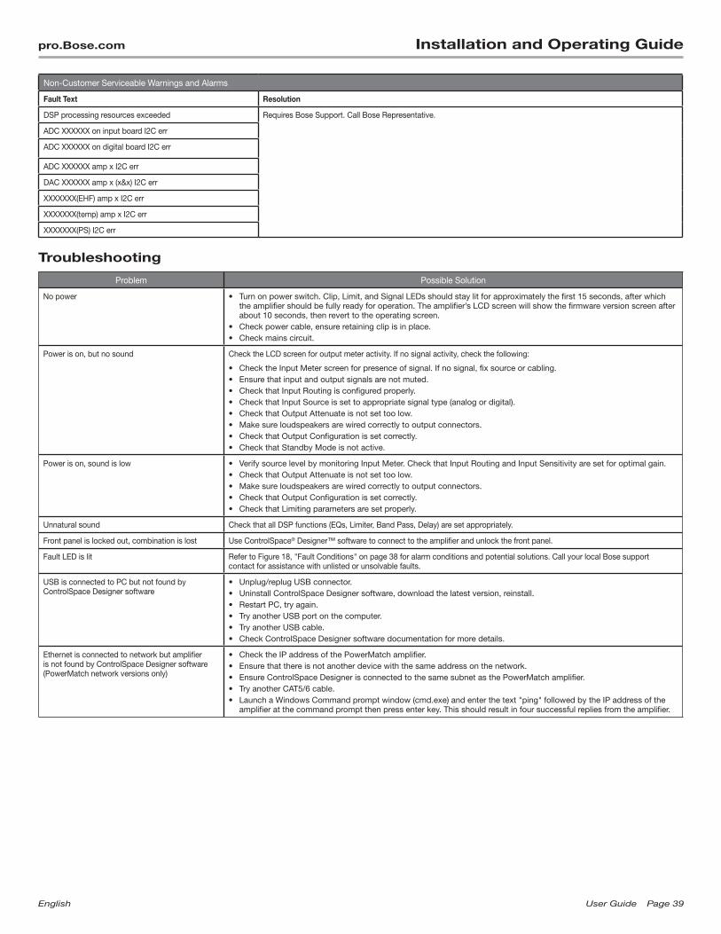
English UserGuide Page39
pro.Bose.com Installation and Operating Guide
Non-Customer Serviceable Warnings and Alarms
Fault Text Resolution
DSP processing resources exceeded Requires Bose Support. Call Bose Representative.
ADC XXXXXX on input board I2C err
ADC XXXXXX on digital board I2C err
ADC XXXXXX amp x I2C err
DAC XXXXXX amp x (x&x) I2C err
XXXXXXX(EHF) amp x I2C err
XXXXXXX(temp) amp x I2C err
XXXXXXX(PS) I2C err
Troubleshooting
Problem Possible Solution
No power • Turn on power switch. Clip, Limit, and Signal LEDs should stay lit for approximately the first 15 seconds, after which the amplifier should be fully ready for operation. The amplifier’s LCD screen will show the firmware version screen after about 10 seconds, then revert to the operating screen.
• Check power cable, ensure retaining clip is in place. • Check mains circuit.
Power is on, but no sound Check the LCD screen for output meter activity. If no signal activity, check the following:
• Check the Input Meter screen for presence of signal. If no signal, fix source or cabling.• Ensure that input and output signals are not muted. • Check that Input Routing is configured properly.• Check that Input Source is set to appropriate signal type (analog or digital).• Check that Output Attenuate is not set too low.• Make sure loudspeakers are wired correctly to output connectors.• Check that Output Configuration is set correctly.• Check that Standby Mode is not active.
Power is on, sound is low • Verify source level by monitoring Input Meter. Check that Input Routing and Input Sensitivity are set for optimal gain.• Check that Output Attenuate is not set too low.• Make sure loudspeakers are wired correctly to output connectors.• Check that Output Configuration is set correctly.• Check that Limiting parameters are set properly.
Unnatural sound Check that all DSP functions (EQs, Limiter, Band Pass, Delay) are set appropriately.
Front panel is locked out, combination is lost Use ControlSpace® Designer™ software to connect to the amplifier and unlock the front panel.
Fault LED is lit Refer to Figure 18, "Fault Conditions" on page 38 for alarm conditions and potential solutions. Call your local Bose support contact for assistance with unlisted or unsolvable faults.
USB is connected to PC but not found by ControlSpace Designer software
• Unplug/replug USB connector.• Uninstall ControlSpace Designer software, download the latest version, reinstall.• Restart PC, try again.• Try another USB port on the computer.• Try another USB cable.• Check ControlSpace Designer software documentation for more details.
Ethernet is connected to network but amplifier is not found by ControlSpace Designer software (PowerMatch network versions only)
• Check the IP address of the PowerMatch amplifier.• Ensure that there is not another device with the same address on the network.• Ensure ControlSpace Designer is connected to the same subnet as the PowerMatch amplifier.• Try another CAT5/6 cable.• Launch a Windows Command prompt window (cmd.exe) and enter the text "ping" followed by the IP address of the
amplifier at the command prompt then press enter key. This should result in four successful replies from the amplifier.
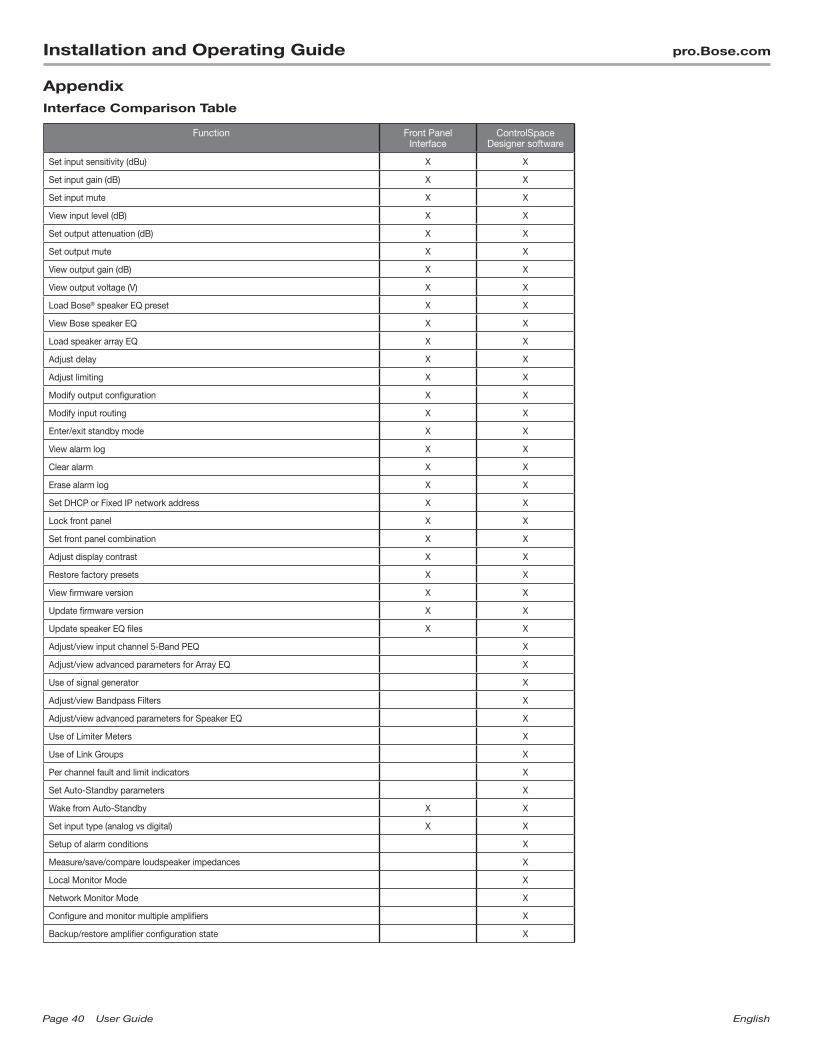
Page40 UserGuide English
Installation and Operating Guide pro.Bose.com
AppendixInterface Comparison Table
Function Front Panel Interface
ControlSpace Designer software
Set input sensitivity (dBu) X X
Set input gain (dB) X X
Set input mute X X
View input level (dB) X X
Set output attenuation (dB) X X
Set output mute X X
View output gain (dB) X X
View output voltage (V) X X
Load Bose® speaker EQ preset X X
View Bose speaker EQ X X
Load speaker array EQ X X
Adjust delay X X
Adjust limiting X X
Modify output configuration X X
Modify input routing X X
Enter/exit standby mode X X
View alarm log X X
Clear alarm X X
Erase alarm log X X
Set DHCP or Fixed IP network address X X
Lock front panel X X
Set front panel combination X X
Adjust display contrast X X
Restore factory presets X X
View firmware version X X
Update firmware version X X
Update speaker EQ files X X
Adjust/view input channel 5-Band PEQ X
Adjust/view advanced parameters for Array EQ X
Use of signal generator X
Adjust/view Bandpass Filters X
Adjust/view advanced parameters for Speaker EQ X
Use of Limiter Meters X
Use of Link Groups X
Per channel fault and limit indicators X
Set Auto-Standby parameters X
Wake from Auto-Standby X X
Set input type (analog vs digital) X X
Setup of alarm conditions X
Measure/save/compare loudspeaker impedances X
Local Monitor Mode X
Network Monitor Mode X
Configure and monitor multiple amplifiers X
Backup/restore amplifier configuration state X
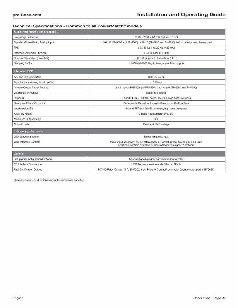
English UserGuide Page41
pro.Bose.com Installation and Operating Guide
Technical Specifications - Common to all PowerMatch® models
Audio Performance Specifications 1
Frequency Response 20 Hz - 20 kHz (@ 1 W and +/- 0.5 dB)
Signal-to-Noise Ratio, Analog Input > 102 dB (PM8500 and PM4500), > 99 dB (PM8250 and PM4250), below rated power, A-weighted
THD < 0.4 % (at 1 W, 20 Hz to 20 kHz)
Intermod Distortion - SMPTE < 0.4 % (60 Hz, 7 kHz)
Channel Separation (Crosstalk) > 65 dB (adjacent channels, at 1 kHz)
Damping Factor > 1000 (10-1000 Hz, 4 ohms, at amplifier output)
Integrated DSP
A/D and D/A Converters 48 kHz / 24-bit
Total Latency (Analog In - Amp Out) < 0.95 ms
Input to Output Signal Routing 8 x 8 matrix (PM8500 and PM8250), 4 x 4 matrix (PM4500 and PM4250)
Loudspeaker Presets Bose Professional
Input EQ 5-band PEQ (+/- 20 dB), notch, shelving, high pass, low pass
Bandpass Filters (Crossover) Butterworth, Bessel, or Linkwitz-Riley, up to 48 dB/octave
Loudspeaker EQ 9-band PEQ (+/- 20 dB), shelving, high pass, low pass
Array EQ Filters 2-band RoomMatch® array EQ
Maximum Output Delay 3 s
Output Limiter Peak and RMS voltage
Indicators and Controls
LED Status Indicators Signal, limit, clip, fault
User Interface Controls Mute, input sensitivity, output attenuation, EQ on/off, preset select. 240 x 64 LCD. Additional controls available w/ ControlSpace® Designer™ software
General
Setup and Configuration Software ControlSpace Designer software V3.2 or greater
PC Interface Connection USB (Network version adds Ethernet RJ45)
Fault Notification Output NC/NO Relay Contact (1 A, 30 VDC), 3-pin Phoenix Contact® connector (orange color; part # 1976010)
(1) Measured at +24 dBu sensitivity unless otherwise specified.
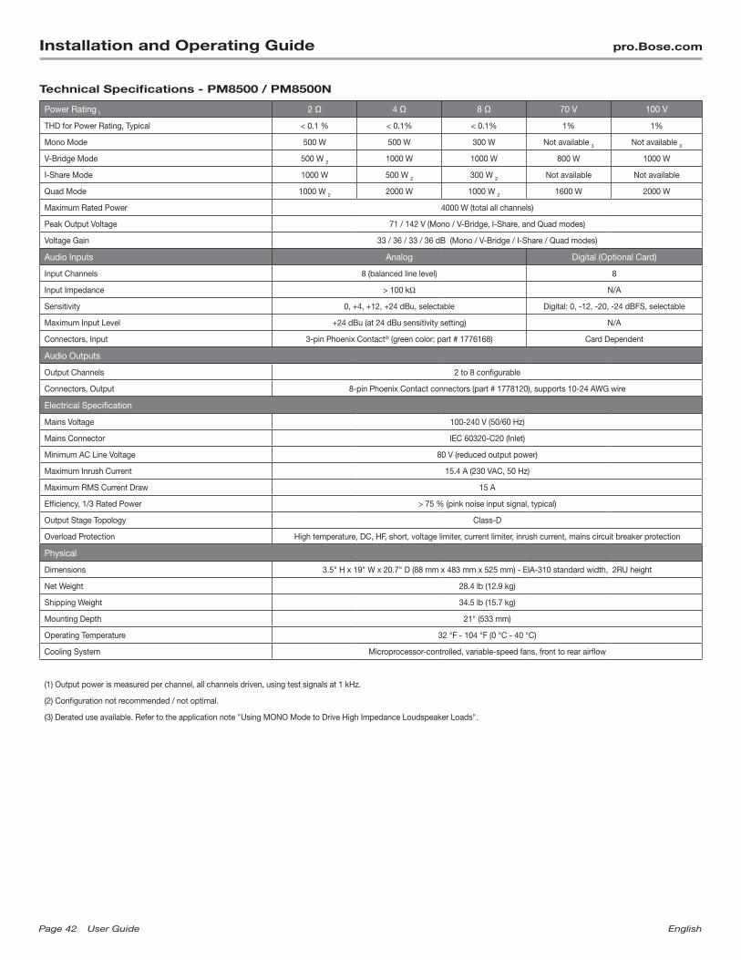
Page42 UserGuide English
Installation and Operating Guide pro.Bose.com
Technical Specifications - PM8500 / PM8500N
Power Rating 1 2 Ω 4 Ω 8 Ω 70 V 100 V
THD for Power Rating, Typical < 0.1 % < 0.1% < 0.1% 1% 1%
Mono Mode 500 W 500 W 300 W Not available 3 Not available 3
V-Bridge Mode 500 W 2 1000 W 1000 W 800 W 1000 W
I-Share Mode 1000 W 500 W 2 300 W 2 Not available Not available
Quad Mode 1000 W 2 2000 W 1000 W 2 1600 W 2000 W
Maximum Rated Power 4000 W (total all channels)
Peak Output Voltage 71 / 142 V (Mono / V-Bridge, I-Share, and Quad modes)
Voltage Gain 33 / 36 / 33 / 36 dB (Mono / V-Bridge / I-Share / Quad modes)
Audio Inputs Analog Digital (Optional Card)
Input Channels 8 (balanced line level) 8
Input Impedance > 100 kΩ N/A
Sensitivity 0, +4, +12, +24 dBu, selectable Digital: 0, -12, -20, -24 dBFS, selectable
Maximum Input Level +24 dBu (at 24 dBu sensitivity setting) N/A
Connectors, Input 3-pin Phoenix Contact® (green color; part # 1776168) Card Dependent
Audio Outputs
Output Channels 2 to 8 configurable
Connectors, Output 8-pin Phoenix Contact connectors (part # 1778120), supports 10-24 AWG wire
Electrical Specification
Mains Voltage 100-240 V (50/60 Hz)
Mains Connector IEC 60320-C20 (Inlet)
Minimum AC Line Voltage 80 V (reduced output power)
Maximum Inrush Current 15.4 A (230 VAC, 50 Hz)
Maximum RMS Current Draw 15 A
Efficiency, 1/3 Rated Power > 75 % (pink noise input signal, typical)
Output Stage Topology Class-D
Overload Protection High temperature, DC, HF, short, voltage limiter, current limiter, inrush current, mains circuit breaker protection
Physical
Dimensions 3.5" H x 19" W x 20.7" D (88 mm x 483 mm x 525 mm) - EIA-310 standard width, 2RU height
Net Weight 28.4 lb (12.9 kg)
Shipping Weight 34.5 lb (15.7 kg)
Mounting Depth 21" (533 mm)
Operating Temperature 32 °F - 104 °F (0 °C - 40 °C)
Cooling System Microprocessor-controlled, variable-speed fans, front to rear airflow
(1) Output power is measured per channel, all channels driven, using test signals at 1 kHz.
(2) Configuration not recommended / not optimal.
(3) Derated use available. Refer to the application note "Using MONO Mode to Drive High Impedance Loudspeaker Loads".

English UserGuide Page43
pro.Bose.com Installation and Operating Guide
Technical Specifications - PM8250 / PM8250N
Power Rating 1
2 Ω 4 Ω 8 Ω 70 V 100 V
THD for Power Rating, Typical < 0.1 % < 0.1% < 0.1% 1% 1%
Mono Mode 250 W 250 W 250 W Not available 3 Not available 3
V-Bridge Mode 250 W 2 500 W 500 W 400 W 500 W
I-Share Mode 500 W 250 W 2 150 W 2 Not available Not available
Quad Mode 1000 W 2 1000 W 500 W 2 800 W 1000 W
Maximum Rated Power 2000 W (total all channels)
Peak Output Voltage 71 / 142 V (Mono / V-Bridge, I-Share, and Quad modes)
Voltage Gain 30 / 33 / 30 / 33 dB (Mono / V-Bridge / I-Share / Quad modes)
Audio Inputs Analog Digital (Optional Card)
Input Channels 8 (balanced line level) 8
Input Impedance > 100 kΩ N/A
Sensitivity 0, +4, +12, +24 dBu, selectable Digital: 0, -12, -20, -24 dBFS, selectable
Maximum Input Level +24 dBu (at 24 dBu sensitivity setting) N/A
Connectors, Input 3-pin Phoenix Contact® (green color; part # 1776168) Card Dependent
Audio Outputs
Output Channels 2 to 8 configurable
Connectors, Output 8-pin Phoenix Contact®connectors (part # 1778120), supports 10-24 AWG wire
Electrical Specification
Mains Voltage 100-240 V (50/60 Hz)
Mains Connector IEC 60320-C14 (Inlet)
Minimum AC Line Voltage 80 V (reduced output power)
Maximum Inrush Current 15.4 A (230 VAC, 50 Hz)
Maximum RMS Current Draw 8 A
Efficiency, 1/3 Rated Power > 68 % (pink noise input signal, typical)
Output Stage Topology Class-D
Overload Protection High temperature, DC, HF, short, voltage limiter, current limiter, inrush current, mains circuit breaker protection
Physical
Dimensions 3.5" H x 19" W x 20.7" D (88 mm x 483 mm x 525 mm) - EIA-310 standard width, 2RU height
Net Weight 28.3 lb (12.8 kg)
Shipping Weight 34.0 lb (15.4 kg)
Mounting Depth 21" (533 mm)
Operating Temperature 32 °F - 104 °F (0 °C - 40 °C)
Cooling System Microprocessor-controlled, variable-speed fans, front to rear airflow
(1) Output power is measured per channel, all channels driven, using test signals at 1 kHz.
(2) Configuration not recommended / not optimal.
(3) Derated use available. Refer to the application note "Using MONO Mode to Drive High Impedance Loudspeaker Loads".
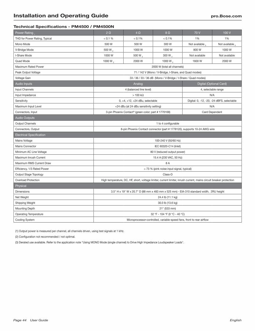
Page44 UserGuide English
Installation and Operating Guide pro.Bose.com
Technical Specifications - PM4500 / PM4500N
Power Rating 1
2 Ω 4 Ω 8 Ω 70 V 100 V
THD for Power Rating, Typical < 0.1 % < 0.1% < 0.1% 1% 1%
Mono Mode 500 W 500 W 300 W Not available 3 Not available 3
V-Bridge Mode 500 W 2 1000 W 1000 W 800 W 1000 W
I-Share Mode 1000 W 500 W 2 300 W 2 Not available Not available
Quad Mode 1000 W 2 2000 W 1000 W 2 1600 W 2000 W
Maximum Rated Power 2000 W (total all channels)
Peak Output Voltage 71 / 142 V (Mono / V-Bridge, I-Share, and Quad modes)
Voltage Gain 33 / 36 / 33 / 36 dB (Mono / V-Bridge / I-Share / Quad modes)
Audio Inputs Analog Digital (Optional Card)
Input Channels 4 (balanced line level) 4, selectable range
Input Impedance > 100 kΩ N/A
Sensitivity 0, +4, +12, +24 dBu, selectable Digital: 0, -12, -20, -24 dBFS, selectable
Maximum Input Level +24 dBu (at 24 dBu sensitivity setting) N/A
Connectors, Input 3-pin Phoenix Contact® (green color; part # 1776168) Card Dependent
Audio Outputs
Output Channels 1 to 4 configurable
Connectors, Output 8-pin Phoenix Contact connector (part # 1778120), supports 10-24 AWG wire
Electrical Specification
Mains Voltage 100-240 V (50/60 Hz)
Mains Connector IEC 60320-C14 (Inlet)
Minimum AC Line Voltage 80 V (reduced output power)
Maximum Inrush Current 15.4 A (230 VAC, 50 Hz)
Maximum RMS Current Draw 8 A
Efficiency, 1/3 Rated Power > 73 % (pink noise input signal, typical)
Output Stage Topology Class-D
Overload Protection High temperature, DC, HF, short, voltage limiter, current limiter, inrush current, mains circuit breaker protection
Physical
Dimensions 3.5" H x 19" W x 20.7" D (88 mm x 483 mm x 525 mm) - EIA-310 standard width, 2RU height
Net Weight 24.4 lb (11.1 kg)
Shipping Weight 30.0 lb (13.6 kg)
Mounting Depth 21" (533 mm)
Operating Temperature 32 °F - 104 °F (0 °C - 40 °C)
Cooling System Microprocessor-controlled, variable-speed fans, front to rear airflow
(1) Output power is measured per channel, all channels driven, using test signals at 1 kHz.
(2) Configuration not recommended / not optimal.
(3) Derated use available. Refer to the application note "Using MONO Mode (single channel) to Drive High Impedance Loudspeaker Loads".
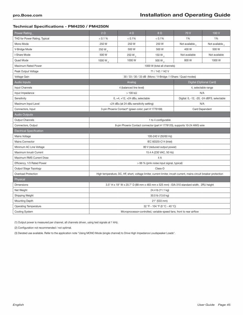
English UserGuide Page45
pro.Bose.com Installation and Operating Guide
Technical Specifications - PM4250 / PM4250N
Power Rating 1
2 Ω 4 Ω 8 Ω 70 V 100 V
THD for Power Rating, Typical < 0.1 % < 0.1% < 0.1% 1% 1%
Mono Mode 250 W 250 W 250 W Not available 3 Not available 3
V-Bridge Mode 250 W 2
500 W 500 W 400 W 500 W
I-Share Mode 500 W 250 W 2
150 W 2
Not available Not available
Quad Mode 1000 W 2
1000 W 500 W 2
800 W 1000 W
Maximum Rated Power 1000 W (total all channels)
Peak Output Voltage 71 / 142 / 142 V
Voltage Gain 30 / 33 / 30 / 33 dB (Mono / V-Bridge / I-Share / Quad modes)
Audio Inputs Analog Digital (Optional Card)
Input Channels 4 (balanced line level) 4, selectable range
Input Impedance > 100 kΩ N/A
Sensitivity 0, +4, +12, +24 dBu, selectable Digital: 0, -12, -20, -24 dBFS, selectable
Maximum Input Level +24 dBu (at 24 dBu sensitivity setting) N/A
Connectors, Input 3-pin Phoenix Contact® (green color; part # 1776168) Card Dependent
Audio Outputs
Output Channels 1 to 4 configurable
Connectors, Output 8-pin Phoenix Contact connector (part # 1778120), supports 10-24 AWG wire
Electrical Specification
Mains Voltage 100-240 V (50/60 Hz)
Mains Connector IEC 60320-C14 (Inlet)
Minimum AC Line Voltage 80 V (reduced output power)
Maximum Inrush Current 15.4 A (230 VAC, 50 Hz)
Maximum RMS Current Draw 4 A
Efficiency, 1/3 Rated Power > 66 % (pink noise input signal, typical)
Output Stage Topology Class-D
Overload Protection High temperature, DC, HF, short, voltage limiter, current limiter, inrush current, mains circuit breaker protection
Physical
Dimensions 3.5" H x 19" W x 20.7" D (88 mm x 483 mm x 525 mm) - EIA-310 standard width, 2RU height
Net Weight 24.4 lb (11.1 kg)
Shipping Weight 30.0 lb (13.6 kg)
Mounting Depth 21" (533 mm)
Operating Temperature 32 °F - 104 °F (0 °C - 40 °C)
Cooling System Microprocessor-controlled, variable-speed fans, front to rear airflow
(1) Output power is measured per channel, all channels driven, using test signals at 1 kHz.
(2) Configuration not recommended / not optimal.
(3) Derated use available. Refer to the application note "Using MONO Mode (single channel) to Drive High Impedance Loudspeaker Loads".

Page46 UserGuide English
Installation and Operating Guide pro.Bose.com
AC Current Draw and Thermal Dissipation Information
PM8500 / PM8500N, AC Current Draw and Thermal Dissipation
Test Signal & Power LevelLoad Configuration
(All Channels Driven)Total Audio Output, W
120VAC 60Hz. Typical Line Current, A
230VAC 50Hz. Typical Line Current, A
Thermal Dissipation, Typical
Watts BTU/hr. kCal/hr.
Idle (Standby, Networked) N/A 0 0.3 0.1 31 106 27
Idle (Awake) N/A 0 1.3 0.7 176 601 151
1/8th Rated Power IEC65 Bandlimited Pink Noise,
6dB Crest Factor
8Ω/Ch Mono 16Ω/Ch V-Bridge
8Ω/Ch Quad300 4.2 2.3 205 699 176
4Ω/Ch Mono 2Ω/Ch I-Share
8Ω/Ch V-Bridge 4Ω/Ch Quad
500 6.4 3.3 272 928 234
1/3rd Rated Power IEC65 Bandlimited Pink Noise,
6dB Crest Factor
8Ω/Ch Mono 16Ω/Ch V-Bridge
8Ω/Ch Quad800 9.3 4.8 275 938 236
4Ω/Ch Mono 2Ω/Ch I-Share
8Ω/Ch V-Bridge 4Ω/Ch Quad
1,333 14.9 7.5 455 1,553 391
PM8250 / PM8250N, AC Current Draw and Thermal Dissipation
Test Signal & Power LevelLoad Configuration
(All Channels Driven)Total Audio Output, W
120VAC 60Hz. Typical Line Current, A
230VAC 50Hz. Typical Line Current, A
Thermal Dissipation, Typical
Watts BTU/hr. kCal/hr.
Idle (Standby, Networked) N/A 0 0.3 0.1 31 106 27
Idle (Awake) N/A 0 1.3 0.7 176 601 151
1/8th Rated Power IEC65 Bandlimited Pink Noise,
6dB Crest Factor
8Ω/Ch Mono 16Ω/Ch V-Bridge
8Ω/Ch Quad250 3.9 2.1 201 686 173
4Ω/Ch Mono 2Ω/Ch I-Share
8Ω/Ch V-Bridge 4Ω/Ch Quad
250 3.9 2.0 214 730 184
1/3rd Rated Power IEC65 Bandlimited Pink Noise,
6dB Crest Factor
8Ω/Ch Mono 16Ω/Ch V-Bridge
8Ω/Ch Quad667 8.0 4.2 281 959 242
4Ω/Ch Mono 2Ω/Ch I-Share
8Ω/Ch V-Bridge 4Ω/Ch Quad
667 8.1 4.1 308 1,051 265
PM4500 / PM4500N, AC Current Draw and Thermal Dissipation
Test Signal & Power LevelLoad Configuration
(All Channels Driven)Total Audio Output, W
120VAC 60Hz. Typi-cal Line Current, A
230VAC 50Hz. Typical Line Current, A
Thermal Dissipation, Typical
Watts BTU/hr. kCal/hr.
Idle (Standby, Networked) N/A 0 0.3 0.1 31 106 27
Idle (Awake) N/A 0 1.0 0.5 176 601 151
1/8th Rated Power IEC65 Bandlimited Pink Noise,
6dB Crest Factor
8Ω/Ch Mono 16Ω/Ch V-Bridge
8Ω/Ch Quad150 2.6 1.6 130 444 112
4Ω/Ch Mono 2Ω/Ch I-Share
8Ω/Ch V-Bridge 4Ω/Ch Quad
250 3.4 1.8 162 553 139
1/3rd Rated Power IEC65 Bandlimited Pink Noise,
6dB Crest Factor
8Ω/Ch Mono 16Ω/Ch V-Bridge
8Ω/Ch Quad400 5.2 3.0 172 587 148
4Ω/Ch Mono 2Ω/Ch I-Share
8Ω/Ch V-Bridge 4Ω/Ch Quad
667 7.6 3.9 241 822 207
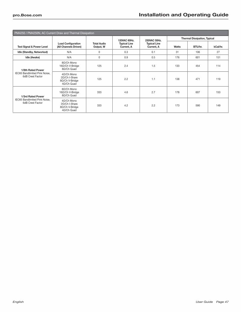
English UserGuide Page47
pro.Bose.com Installation and Operating Guide
PM4250 / PM4250N, AC Current Draw and Thermal Dissipation
Test Signal & Power LevelLoad Configuration
(All Channels Driven)Total Audio Output, W
120VAC 60Hz. Typical Line Current, A
230VAC 50Hz. Typical Line Current, A
Thermal Dissipation, Typical
Watts BTU/hr. kCal/hr.
Idle (Standby, Networked) N/A 0 0.3 0.1 31 106 27
Idle (Awake) N/A 0 0.9 0.5 176 601 151
1/8th Rated Power IEC65 Bandlimited Pink Noise,
6dB Crest Factor
8Ω/Ch Mono 16Ω/Ch V-Bridge
8Ω/Ch Quad125 2.4 1.5 133 454 114
4Ω/Ch Mono 2Ω/Ch I-Share
8Ω/Ch V-Bridge 4Ω/Ch Quad
125 2.2 1.1 138 471 119
1/3rd Rated Power IEC65 Bandlimited Pink Noise,
6dB Crest Factor
8Ω/Ch Mono 16Ω/Ch V-Bridge
8Ω/Ch Quad333 4.6 2.7 178 607 153
4Ω/Ch Mono 2Ω/Ch I-Share
8Ω/Ch V-Bridge 4Ω/Ch Quad
333 4.2 2.2 173 590 149

Page48 UserGuide English
Installation and Operating Guide pro.Bose.com

English UserGuide Page49
pro.Bose.com Installation and Operating Guide

Page50 UserGuide English
Installation and Operating Guide pro.Bose.com
English Page51 UserGuide
pro.Bose.com Additional Resources
Additional Resources
Visit us on the web at pro.Bose.com for more information, including specifications, technical literature, product warranty, parts and accessories, and global support contact information.
Americas (USA, Canada, Mexico, Central America, South America) Bose Corporation The Mountain Framingham, MA 01701 USA Corporate Center: 508-879-7330 Americas Professional Systems, Technical Support: 800-994-2673
Australia Bose Pty Limited Unit 3/2 Holker Street Newington NSW Australia 61 2 8737 9999
Belgium Bose N.V. / S.A Limesweg 2, 03700 Tongeren, Belgium 012-390800
China Bose Electronics (Shanghai) Co. Ltd. 36F, West Gate Tower 1038 West Nanjing Road Shanghai, P.R.C. 200041 China 86 21 6271 3800
France Bose S.A.S 12 rue de Temara 78100 St. Germain-en-Laye, France 01-30616363
Germany Bose GmbH Max-Planck Strasse 36D 61381 Friedrichsdorf, Deutschland 06172-7104-0
Hong Kong Bose Limited Suites 2101-2105, Tower One, Times Square 1 Matheson Street, Causeway Bay, Hong Kong 852 2123 9000
India Bose Corporation India Private Limited 4th Floor, Shriram Bhartiya Kala Kendra 1, Copernicus Marg New Delhi 110001, India 91 11 23073825
Italy Bose SpA Via Della Magliana 87600148 Rome, Italy 066-5670802
Japan Bose Kabushiki Kaisha Sumitomo Fudosan Shibuya Garden Tower 5F 16-17, Nanpeidai-cho Shibuya-Ku, Tokyo, 150-0036, Japan
TEL 81-3-5489-0955 www.bose.co.jp
The Netherlands Bose BV Nijverheidstraat 8 1135 GE Edam, Nederland 0299-390139
United Kingdom Bose Ltd 1 Ambley Green, Gillingham Business Park KENT ME8 0NJ Gillingham, England 0870-741-4500
See website for other countries.
COMBICON is a registered trademark of Phoenix Contact GmbH & Co.
Phoenix Contact is a registered trademark of Phoenix Contact GmbH & Co.
CobraNet is a registered trademark of Cirrus Logic, Inc.

© 2013 Bose Corporation. All rights reserved.The Mountain, Framingham, MA 01701-9168 USA
www.pro.Bose.comAll trademarks are the property of their respective owners.
AM364052 Rev. 00