Embed Size (px)
Citation preview
8/19/2019 Powermac Server g3 Minitower
http://slidepdf.com/reader/full/powermac-server-g3-minitower 1/292
Service SourcK
Power Macintosh/Server
G3 Minitowe
8/19/2019 Powermac Server g3 Minitower
http://slidepdf.com/reader/full/powermac-server-g3-minitower 2/292
Service SourcK
Hot IssuePower Macintosh/Server G3
Minitowe
8/19/2019 Powermac Server g3 Minitower
http://slidepdf.com/reader/full/powermac-server-g3-minitower 3/292
Hot Issues Introduction -
IntroductionThis chapter is designed to highlight unique or high-priority product issues that you should be aware of beforeservicing the Power Macintosh G3 Minitower or Macintosh
Server G3 computers.
This chapter alerts you to important issues and provideslinks to other areas in the manual where more completeinformation can be found. This chapter is not intended toreplace other parts of this manual; it merely provides apointer to pertinent information in those chapters.
To familiarize yourself with a new product family, always
read the Basics chapter in its entirety.
8/19/2019 Powermac Server g3 Minitower
http://slidepdf.com/reader/full/powermac-server-g3-minitower 4/292
Hot Issues Shared Logic Board - 2
Shared Logic BoardThe Power Macintosh G3 Desktop, G3 Minitower, andMacintosh Server G3 computers use the same logic board,but there are jumper settings that differ between them (see
“Jumper Location J28” and “Jumper Location J16” in theTroubleshooting chapter).
Processor Module Vs. CardWhereas previous Power Macintosh computers featured auser-installable processor card, this logic board uses aprocessor module that must not be removed by the customer(see “Processor Module” in the Take-Apart chapter).
8/19/2019 Powermac Server g3 Minitower
http://slidepdf.com/reader/full/powermac-server-g3-minitower 5/292
Hot Issues Power Supply Jumper - 3
Power Supply JumperThe Power Macintosh/Server G3 Minitower logic board hasa power supply jumper installed at J28. The setting of this
jumper differs between the Power Mac G3 Desktop and
Power Mac/Server G3 Minitower models. Failure to installthis jumper in the correct position may result in acomputer that won’t boot up. (See “Jumper Location J28”in the Troubleshooting chapter.)
Processor Module JumperThe Power Mac/Server G3 logic board has a processormodule jumper installed at J16. The processor jumper iscolor coded for the speed of processor module used. Failureto install the correct jumper may result in a computer thatwon’t boot up. (See “Jumper Location J16” in the
8/19/2019 Powermac Server g3 Minitower
http://slidepdf.com/reader/full/powermac-server-g3-minitower 6/292
Hot Issues Warranty Sticker - 4
Troubleshooting chapter.)
Warranty StickerThere is a warranty sticker that covers the processormodule jumper. The customer’s warranty is void if thissticker is tampered with. Service Providers must replacethis sticker if they have removed it during servicing toprotect the customer’s warranty. (See “Processor Module”in the Take-Apart chapter.)
Power Supply Voltage SettingThere is a switch on the back of the power supply thatcontrols the voltage setting. The voltage switch must be secorrectly to avoid damaging the computer. (See “Voltage
8/19/2019 Powermac Server g3 Minitower
http://slidepdf.com/reader/full/powermac-server-g3-minitower 7/292
8/19/2019 Powermac Server g3 Minitower
http://slidepdf.com/reader/full/powermac-server-g3-minitower 8/292
Hot Issues ROM DIMM
ROM DIMMThe Power Mac/Server G3 Minitower logic board uses aROM DIMM as opposed to soldered ROM. You should notremove the ROM DIMM from the logic board. (See “Logic
Board” in the Take-Apart chapter for instructions on how toprepare the logic board for return to Apple Computer.)
SDRAM DIMMsThe Power Mac/Server G3 Minitower uses SDRAM DIMMs.DIMMs from older Macintosh computers, although they willfit, are not compatible and should never be used in the PowerMac/Server G3 computers. (See “SDRAM DIMMs” in theBasics chapter and refer to the Power Macintosh G3Minitower or Macintosh Server G3 sections of the MemoryGuide.)
8/19/2019 Powermac Server g3 Minitower
http://slidepdf.com/reader/full/powermac-server-g3-minitower 9/292
Hot Issues SGRAM Video Memory -
SGRAM Video MemoryPower Mac/Server G3 computers use SGRAM video memory.Use only SGRAM SO-DIMMs in these machines. Never installthe 256K or 512K video memory DIMMs used in older
Macintosh computers. (See “SGRAM Video Memory” in theBasics chapter.)
EIDE Bus IssueIf you have only one device connected to the EIDE bus, thedevice must be plugged into the first EIDE connector on thelogic board (the one closer to the rear panel), which ismarked J9. If you plug the device into J10 and leave J9empty, the device may not boot up. (See “Connecting EIDEDevices to the Logic Board” in the Basics chapter.)
8/19/2019 Powermac Server g3 Minitower
http://slidepdf.com/reader/full/powermac-server-g3-minitower 10/292
Hot Issues Master/Slave Support - 8
Master/Slave SupportSome Power Mac/Server G3 computers support adding twoATA/IDE devices to the same ATA/IDE channel, or what iscommonly known as master and slave. This configuration
provides user with the ability to add additional hard drivesor removal media devices to their system. Because thecabling is different, you cannot replace ATA drives with SCSIdrives and vice versa. (See “Support for Master and Slave”in the Basics chapter.)
Ultra Wide SCSI Cable RoutingThe Ultra Wide SCSI cable (if present) must be routedinside the computer’s chassis in a very specific manner.Failure to route the cable correctly could result inperformance problems. (See “Ultra Wide SCSI PCI Card” in

8/19/2019 Powermac Server g3 Minitower
http://slidepdf.com/reader/full/powermac-server-g3-minitower 11/292
Hot Issues DVD-ROM Disk Damage -
the Take-Apart chapter.)
DVD-ROM Disk DamageThe Power Macintosh G3 Minitower and Macintosh ServerG3 offer DVD-ROM drives as a build-to-order option. It isimportant to note that DVD disks are much more prone todamage than CD-ROM disks. Any type of scratch or otherabuse may result in a disk that is unreadable. (See “DVD-ROM Drive Technology” in the Basics chapter.)
8/19/2019 Powermac Server g3 Minitower
http://slidepdf.com/reader/full/powermac-server-g3-minitower 12/292
Hot Issues HFS+ Formatted Drives - 10
HFS+ Formatted DrivesHard drives that ship with the Version 2 Power MacintoshG3 logic board (part number 661-2063) use a file formatcalled Mac OS Extended format, also referred to as HFS+.
Norton Utilities version 3.5 is not compatible with Mac OSand version 3.5.1 and earlier can result in hard drivecorruption and loss of all data on the hard drive. If youexperience problems with a hard drive in one of thesesystems, Apple Computer recommends using the version ofDisk First Aid included on the system software CD thatshipped with the unit. (See “HFS+ Formatted Drives” in theTroubleshooting chapter.)
8/19/2019 Powermac Server g3 Minitower
http://slidepdf.com/reader/full/powermac-server-g3-minitower 13/292
Hot Issues PM G3 Minitower "Sleep/Beep" Issue - 11
PM G3 Minitower "Sleep/Beep" IssueA problem has been reported with some of the AV I/O cardsinstalled in the Power Macintosh G3 Minitower computer.Systems with the problem exhibit the following symptoms:
The computer goes into sleep mode and begins beeping about2 times a second. Then one of three things happens:
1 The computer wakes itself up after 3 to 4 seconds.
2 The user is able to wake up the computer in a normalfashion.
3 The user is unable to wake the computer.
Note: this problem only occurs on the Minitower version ofthe Power Macintosh G3 computer and only with the AV I/Ocard installed (that is, the problem does not occur with theAudio Only card).
8/19/2019 Powermac Server g3 Minitower
http://slidepdf.com/reader/full/powermac-server-g3-minitower 14/292
Hot Issues PM G3 Minitower "Sleep/Beep" Issue - 12
To resolve this issue, replace the AV I/O card (p/n 661-1456) only if the customer's system meets both of thefollowing criteria:• The computer has a serial number date range of
xxx42xxxxxx-xxx47xxxxxx; and
• The AV I/O card has not been repaired already (see"Identifying Repaired Cards" below).
Identifying Repaired Cards
Repaired cards will have a blue dot on the back fence of thecard, OR the system serial number will have an “AA”appended to the serial number label. Make sure that you arenot replacing a repaired card for this problem.

8/19/2019 Powermac Server g3 Minitower
http://slidepdf.com/reader/full/powermac-server-g3-minitower 15/292
Hot Issues Power-On Issue - 1
Power-On IssueIf you experience a power-on issue with the PowerMacintosh G3 Minitower or Macintosh Server G3 where thepower supply fan is spinning, but there is no boot tone, no
hard drive noise, no power LED, and no video, you may havean improperly installed or faulty voltage regulator. Youshould always reseat and/or replace the voltage regulatorbefore replacing the logic board. (See “System” symptom/cures in the Troubleshooting chapter.)
8/19/2019 Powermac Server g3 Minitower
http://slidepdf.com/reader/full/powermac-server-g3-minitower 16/292
Service SourcK
BasicPower Mac/Server G3 Minitower
8/19/2019 Powermac Server g3 Minitower
http://slidepdf.com/reader/full/powermac-server-g3-minitower 17/292
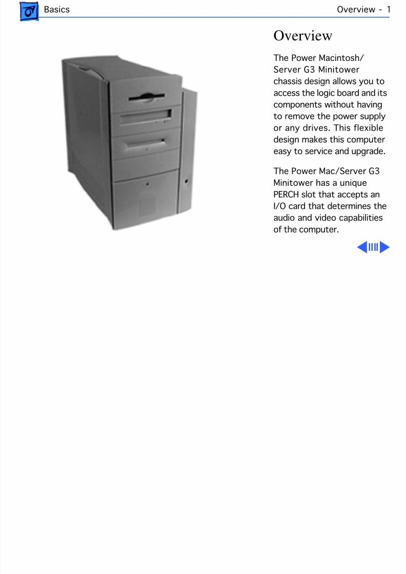
Basics Overview
OverviewThe Power Macintosh/Server G3 Minitowerchassis design allows you to
access the logic board and itscomponents without havingto remove the power supplyor any drives. This flexibledesign makes this computereasy to service and upgrade.
The Power Mac/Server G3Minitower has a uniquePERCH slot that accepts anI/O card that determines theaudio and video capabilitiesof the computer.
8/19/2019 Powermac Server g3 Minitower
http://slidepdf.com/reader/full/powermac-server-g3-minitower 18/292
Basics Features -
FeaturesThere are standard features available with every PowerMacintosh G3 Minitower computer as well as build-to-order features that are optional. The standard and optional
features are listed below:
Standard Power Mac G3 Minitower Features:• 233 MHz, 266 MHz, 300, or 333 MHz PowerPC G3
microprocessor• RAM expandable to 384 MB in three DIMM card slots
using 64-bit, 168-pin, JEDEC-standard, 3.3 V,unbuffered, SDRAM DIMM cards
• 512K backside L2 cache (233 and 266 MHz) or 1 MBbackside L2 cache (300 and 333 MHz) on processor
• Built-in 2D and 3D hardware graphics acceleration• PERCH slot to support Apple I/O cards• One modem slot on I/O cards for optional fax/modem card
8/19/2019 Powermac Server g3 Minitower
http://slidepdf.com/reader/full/powermac-server-g3-minitower 19/292
Basics Features -
• 4 GB or 6 GB ATA hard drive• CD-ROM ATAPI drive at 24X speed (unless customer
orders DVD-ROM drive)• 1.4 MB SuperDrive• Three expansion bays for adding internal 3.5” SCSI
devices• One SCSI port• Two GeoPort serial ports• 10BASE-T Ethernet port• One ADB port• Three PCI expansion slots to accept three 12” PCI cards,
or three 15 W cards, or two 25 W cards• Voltage switch• Fan speed thermally controlled• Energy Saver control panel• 2 MB video RAM expandable to 4 MB or 6 MB with
3.3 V, 83 MHz or faster SGRAM on a 144-pin smalloutline dual inline memory module (SO-DIMM)
8/19/2019 Powermac Server g3 Minitower
http://slidepdf.com/reader/full/powermac-server-g3-minitower 20/292
Basics Features -
Optional Build-to-Order Power Mac G3 MinitowerFeatures:• 100 MB SCSI Iomega or ATAPI Zip drive in the expansion
bay• Ultra Wide SCSI PCI card
• 4 GB or 9 GB Ultra Wide 3.5” SCSI hard drive(s)(replaces 4 GB or 6 GB ATA hard drive(s))• DVD-ROM Drive (in place of CD-ROM drive)• 8 MB IX Micro 3D graphics accelerator card• 10/100 BaseT ethernet card• FireWire DVC card
Features of the Macintosh Server G3 include• 233 MHz, 266 MHz, 300, or 333 MHz PowerPC G3
microprocessor• RAM expandable to 384 MB in three DIMM card slots
using 64-bit, 168-pin, JEDEC-standard, 3.3 V,unbuffered, SDRAM DIMM cards
8/19/2019 Powermac Server g3 Minitower
http://slidepdf.com/reader/full/powermac-server-g3-minitower 21/292
Basics Features -
• 512K backside L2 cache (233 and 266 MHz) or 1 MBbackside L2 cache (300 and 333 MHz) on processor
• Built-in 2D and 3D hardware graphics acceleration• PERCH slot to support Apple I/O cards• One modem slot on I/O cards for optional fax/modem card
• 4 GB or 9 GB Ultra Wide 3.5” SCSI hard drive(s)• Ultra Wide SCSI PCI card• 10/100 BaseT ethernet card• Three expansion bays for adding internal 3.5’’ SCSI
devices (CD-ROM drive pre-installed in one bay)• CD-ROM ATAPI drive at 24X speed (unless customer
orders DVD-ROM drive)• 1.4 MB SuperDrive• One SCSI port• Two GeoPort serial ports• 10BASE-T Ethernet port• One ADB port• Three PCI expansion slots to accept three 12” PCI cards,
8/19/2019 Powermac Server g3 Minitower
http://slidepdf.com/reader/full/powermac-server-g3-minitower 22/292
Basics Features -
or three 15 W cards, or two 25 W cards (two slots filledin standard Server G3 configuration with 10/100 BaseTethernet card and Ultra Wide SCSI PCI card; one to twoslots filled only in build-to-order G3 Minitowerconfigurations with 10/100 BaseT ethernet card and/or
Ultra Wide SCSI PCI card)• Voltage switch• Fan speed thermally controlled• Energy Saver control panel• 2 MB video RAM expandable to 4 MB or 6 MB with
3.3 V, 83 MHz or faster SGRAM on a 144-pin smalloutline dual inline memory module (SO-DIMM)
Optional Build-to-Order Macintosh Server G3Features:• 6 GB ATA hard drive (in place of Ultra Wide SCSI drive)• DVD-ROM drive (in place of CD-ROM drive)• DDS-3 tape drive
8/19/2019 Powermac Server g3 Minitower
http://slidepdf.com/reader/full/powermac-server-g3-minitower 23/292
Basics Features -
Software included with Macintosh Server G3 Units:• Mac OS 8.1, specifically tuned for server use• AppleShare IP 5.0 server software• Apple Network Administrator Toolkit network
management software
• SoftRAID volume management software• Virex 5.8
8/19/2019 Powermac Server g3 Minitower
http://slidepdf.com/reader/full/powermac-server-g3-minitower 24/292
Basics Data Buses -
Data BusesThe data buses on the Power Macintosh G3 Minitower andMacintosh Server G3 include:• Narrow SCSI-1: The SCSI-1 chain transfers data at up to
5 MB per second. The narrow SCSI-1 chain supports upto seven internal and external SCSI devices. The NarrowSCSI-1 bus is used to connect the ZIP drive (if present)and any SCSI-1 hard drives.
• Ultra Wide SCSI-3 (provided on Ultra Wide SCSI card,which is optional on the G3 Minitower and standard onthe Server G3): The Ultra Wide SCSI-3 chain cantransfer data at up to 40 MB per second and supports up
to three internal devices. This bus is used to connect anyUltra Wide SCSI devices.• EIDE (Extended Integrated Drive Electronics): There are
two EIDE connectors on the logic board (the ATAPI CD-ROM drive or DVD-ROM drive uses one of these
8/19/2019 Powermac Server g3 Minitower
http://slidepdf.com/reader/full/powermac-server-g3-minitower 25/292
Basics Data Buses -
connectors, and if an ATA hard drive is installed, it usesthe second connector). In the standard G3 Minitowerconfiguration, both channels are in use. In the standardG3 Server configuration, one EIDE channel is available.
Note: Some Power Mac G3 system use a Master/Slaveinterface. See “Support for Master and Slave” later in thissection for more information.
The following table gives more information about the databuses in the Power Macintosh G3 Minitower and MacintoshServer G3 computers.
8/19/2019 Powermac Server g3 Minitower
http://slidepdf.com/reader/full/powermac-server-g3-minitower 26/292
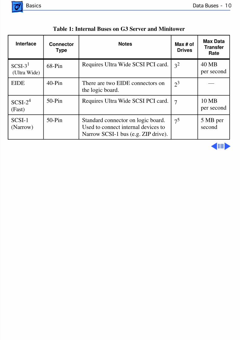
Basics Data Buses - 1
Table 1: Internal Buses on G3 Server and Minitower
Interface ConnectorType
Notes Max # ofDrives
Max DatTransfer
Rate
CSI-3 1
Ultra Wide)68-Pin Requires Ultra Wide SCSI PCI card. 32 40 MB
per secon
IDE 40-Pin There are two EIDE connectors onthe logic board.
23 —
CSI-2 4 Fast)
50-Pin Requires Ultra Wide SCSI PCI card. 7 10 MBper secon
CSI-1Narrow)
50-Pin Standard connector on logic board.Used to connect internal devices toNarrow SCSI-1 bus (e.g. ZIP drive).
75 5 MB pesecond
8/19/2019 Powermac Server g3 Minitower
http://slidepdf.com/reader/full/powermac-server-g3-minitower 27/292
Basics Data Buses - 1
Notes for Table 1:
1 The Ultra Wide SCSI PCI card is optional on G3 Minitower and standard on G3 Server. TheApple Ultra Wide SCSI card and cable allow you to connect a maximum of 3 devices to thisbus.2 Physical space inside the computer limits this number to 3.3 The ATAPI CD-ROM drive, ATAPI DVD-ROM drive, and ATA hard drive (if present) usehis bus.
4 Ultra Wide SCSI PCI card is optional on G3 Minitower and standard on G3 Server. It’sbest not to use this bus because it will cause any Ultra Wide SCSI-3 devices to transferdata at the slower SCSI-2 rate. No cable is provided for the SCSI-2 bus.5 The G3 Minitower comes with a Zip drive attached to this bus. The standard G3 Serverconfiguration does not use this bus; however, an internal cable may be provided that canconnect up to two internal SCSI-1 devices. You can add additional SCSI-1 devices as long ashe combined number of internal and external devices is no more than seven.
8/19/2019 Powermac Server g3 Minitower
http://slidepdf.com/reader/full/powermac-server-g3-minitower 28/292
Basics Data Buses - 1
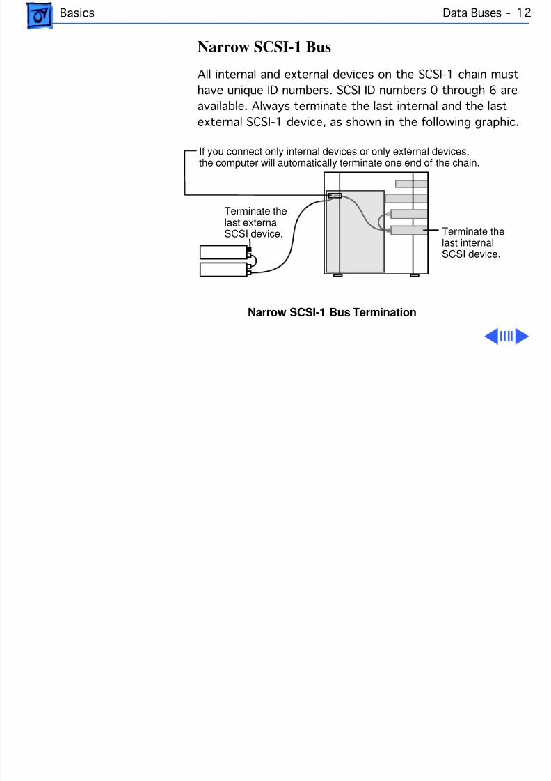
Narrow SCSI-1 Bus
All internal and external devices on the SCSI-1 chain musthave unique ID numbers. SCSI ID numbers 0 through 6 areavailable. Always terminate the last internal and the lastexternal SCSI-1 device, as shown in the following graphic.
Narrow SCSI-1 Bus Termination
Terminate thelast externalSCSI device. Terminate the
last internal
SCSI device.
If you connect only internal devices or only external devices,the computer will automatically terminate one end of the chain.
8/19/2019 Powermac Server g3 Minitower
http://slidepdf.com/reader/full/powermac-server-g3-minitower 29/292
Basics Data Buses - 1
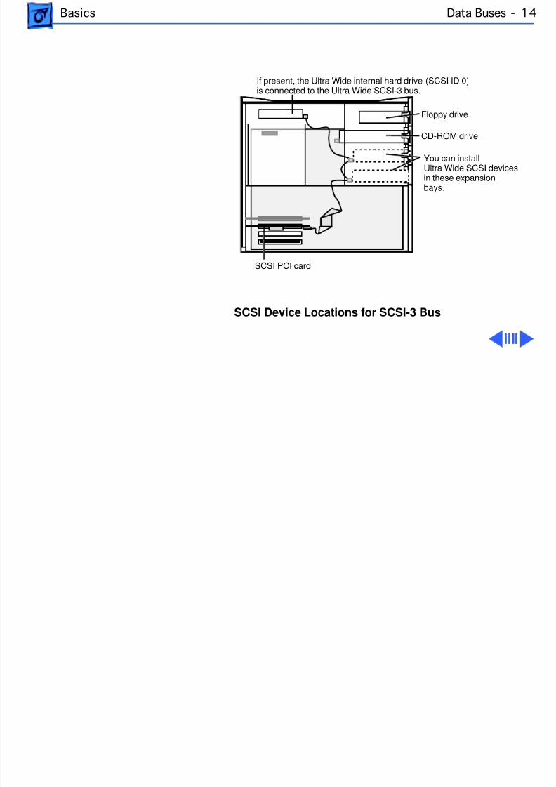
Ultra Wide SCSI-3 Bus
Ultra Wide SCSI support is offered on the Power MacintoshG3 Minitower (optional feature) and G3 Server (standardfeature) via an Ultra Wide SCSI PCI card (p/n 661-2011).If present, this card is installed in the first PCI slot on thelogic board. You can connect a total of three internal devicesto the Ultra Wide SCSI-3 bus.
Important : Before you connect an internal device to the UltraWide SCSI-3 bus, refer to the information on cable lengthlimits and termination later in this section.
The following illustration shows where to install SCSI
devices for use with the Ultra Wide SCSI-3 bus and how toroute the Ultra Wide cable. (Note: More detailed informationon how to route and tape the Ultra Wide SCSI cable can befound in the Take-Apart chapter in the Hard Drive topic.)
8/19/2019 Powermac Server g3 Minitower
http://slidepdf.com/reader/full/powermac-server-g3-minitower 30/292
Basics Data Buses - 1
SCSI Device Locations for SCSI-3 Bus
If present, the Ultra Wide internal hard drive (SCSI ID 0)is connected to the Ultra Wide SCSI-3 bus.
SCSI PCI card
CD-ROM drive
Floppy drive
You can installUltra Wide SCSI devicesin these expansionbays.
8/19/2019 Powermac Server g3 Minitower
http://slidepdf.com/reader/full/powermac-server-g3-minitower 31/292
Basics Data Buses - 1
All devices on the same SCSI bus must have unique IDnumbers, but devices on different SCSI buses may use thesame SCSI ID number. (For example, you could have aremovable media drive with ID number 3 connected to theNarrow SCSI-1 bus and a hard drive with ID number 3
connected to the Ultra Wide SCSI-3 bus.)Some of the drives that were installed at the factory, as wellas the SCSI card itself, have already reserved certain SCSIID numbers on the Ultra Wide SCSI-3 bus. Other IDnumbers are available for assignment to SCSI devices thatare added later.
The following table provides more information on assigning
SCSI ID numbers to Ultra Wide devices.
8/19/2019 Powermac Server g3 Minitower
http://slidepdf.com/reader/full/powermac-server-g3-minitower 32/292
Basics Data Buses - 1
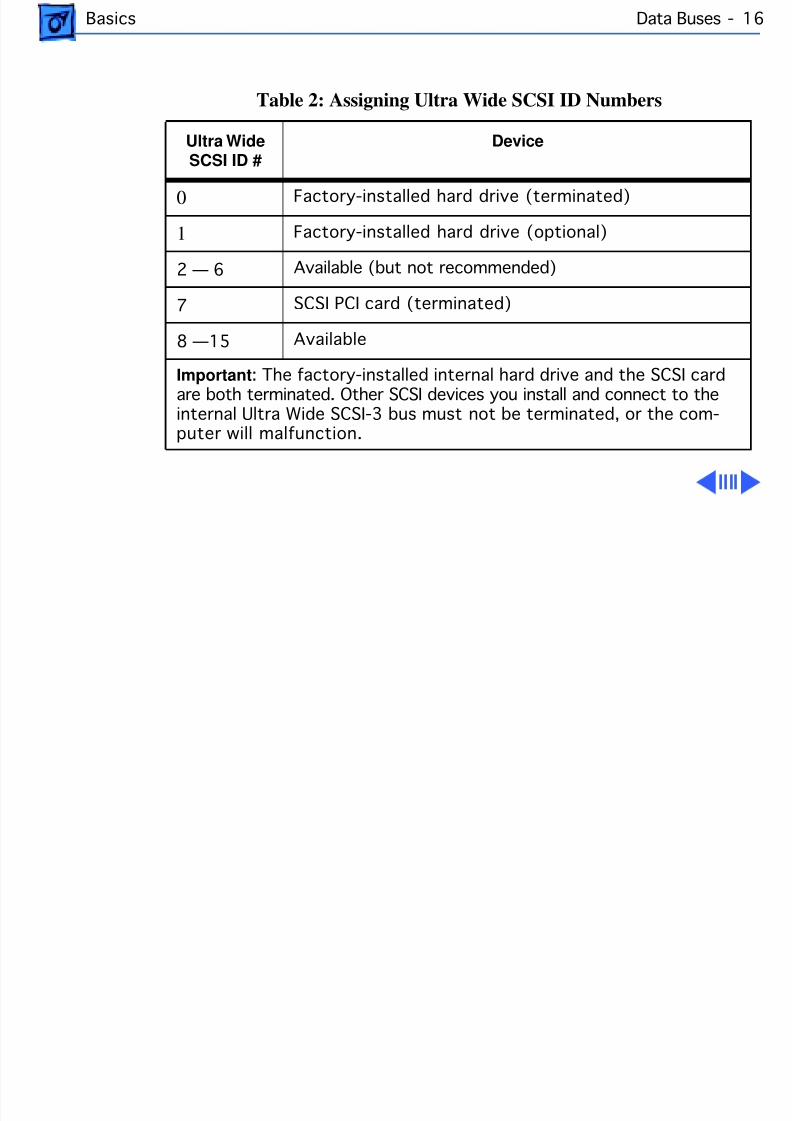
Table 2: Assigning Ultra Wide SCSI ID Numbers
Ultra WideSCSI ID #
Device
0 Factory-installed hard drive (terminated)
1 Factory-installed hard drive (optional)
2 — 6 Available (but not recommended)
7 SCSI PCI card (terminated)
8 —15 Available
Important : The factory-installed internal hard drive and the SCSI cardare both terminated. Other SCSI devices you install and connect to theinternal Ultra Wide SCSI-3 bus must not be terminated, or the com-puter will malfunction.
8/19/2019 Powermac Server g3 Minitower
http://slidepdf.com/reader/full/powermac-server-g3-minitower 33/292
Basics Data Buses - 1
EIDE Bus
The internal EIDE bus supports the internal CD-ROM orDVD-ROM drive. You can connect another EIDE device, suchas an EIDE hard drive, to the second channel of the EIDE bus.(Note that in the standard G3 Minitower configuration, thereis already an ATA hard drive attached to the second EIDEchannel. Some build-to-order G3 Minitowers, however,come with the optional Ultra Wide SCSI card and Ultra WideSCSI hard drive, in which case the second EIDE channel isavailable.) You can install an EIDE device in one of theavailable expansion bays.
Connecting EIDE Devices to the Logic Board
There are two EIDE connectors on the G3 Minitower logicboard, which are marked J9 and J10. Use the internalribbon cable with the 40-pin connector to connect EIDE
8/19/2019 Powermac Server g3 Minitower
http://slidepdf.com/reader/full/powermac-server-g3-minitower 34/292
Basics Data Buses - 1
devices to the EIDE bus.
If you are connecting a single device to the EIDE bus, youshould use the J9 connector (the one closer to the rearpanel). If you plug a single device into the J10 EIDEconnector and leave J9 empty, the device may not boot.However, if the system is booting from a device that has theApple CD-ROM driver v 5.4.1 or later installed, you canconnect a single CD-ROM drive to either the J9 or J10connector, and the system will recognize it.
If the Power Macintosh G3 Minitower ships with two EIDEdevices (a CD-ROM or DVD-ROM drive and an ATA harddrive), both EIDE connectors (J9 and J10) will be
automatically used. Service Providers should keep the J9 vs.J10 issue in mind, however, when testing G3 Minitowerunits.
8/19/2019 Powermac Server g3 Minitower
http://slidepdf.com/reader/full/powermac-server-g3-minitower 35/292
Basics Data Buses - 1
Support for Master and Slave
Some Power Mac/Server G3 computers support adding twoATA/IDE devices to the same ATA/IDE channel, or what iscommonly known as master and slave. This configurationprovides user with the ability to add additional hard drivesor removal media devices to their system.
The Power Macintosh G3 Minitower and Macintosh ServerG3 units that support this feature can only be identified bylooking at the logic board itself and verifying the revision ofthe built-in video ASIC made by ATI Technologies. If you arelooking at the logic board with the rear connector towardsyou, the video ASIC is located approximately 1” from the
built-in video connector on the logic board.
If the ASIC reads: “ATI 3D Rage II+DVD,” the logic boarddoes not support the master and slave configuration; If thecontroller reads: “ATI 3D Rage Pro PCI,” the logic board
8/19/2019 Powermac Server g3 Minitower
http://slidepdf.com/reader/full/powermac-server-g3-minitower 36/292
Basics Data Buses - 2
does support the master and slave configuration.
Note: Although the ATI chip is an ideal way to identify theversion of the logic board, it does not control the EIDEinterface.
Conguring or Connecting Master/Slave Devices
Each IDE channel can support either one or two devices. AllPower Macintosh G3's have two ATA/IDe channels. ATA/IDEdevices each contain their own integrated controllers, and soin order to maintain order on the channel, it is necessary tohave some way of differentiating between the two devices.This is done by giving each device a designation as either
master or slave, and then having the controller addresscommands and data to either one or the other. The drive thatis the target of the command responds to it, and the other oneremains silent.
8/19/2019 Powermac Server g3 Minitower
http://slidepdf.com/reader/full/powermac-server-g3-minitower 37/292
Basics Data Buses - 2
Note: Despite the hierarchical-sounding names of "master"and "slave", the master drive does not have any specialstatus compared to the slave one; they are really equals inmost respects. The slave drive doesn't rely on the masterdrive or anything like that, despite the names.
Devices are designated as master or slave using jumpers,small connectors that fit over pairs of pins to program thedrive through hardware. Each hard drive manufacturer usesa different combination of jumpers (usually nameddifferently) for specifying whether its drive is master orslave on the channel. Some disks put this information righton the top label of the drive itself, while many do not; itsometimes takes some hunting around to find where the
jumper pins are on the drive even once you know how the jumpers are supposed to go.
ATAPI drives, or ATA/IDE devices that support removable
8/19/2019 Powermac Server g3 Minitower
http://slidepdf.com/reader/full/powermac-server-g3-minitower 38/292
Basics Data Buses - 2
media like CD-ROM's are jumpered in exactly the same way,and they have the advantage of having their jumpers muchmore universally labeled than their hard disk counterparts.
If you are using two drives on a channel, it is important toensure that they are jumpered correctly. Making bothdrives the master, or both the slave will likely result in avery confused system.
Note : It makes no difference which connector on the ATA/IDE cable is used in a standard ATA/IDE setup, because it isthe jumpers that control master and slave, not the cable. Aslong as one device is jumpered as master and the other asslave, any two ATA/IDE or ATAPI devices should work
together on a single channel.
8/19/2019 Powermac Server g3 Minitower
http://slidepdf.com/reader/full/powermac-server-g3-minitower 39/292
Basics Expansion Bays - 2
Expansion BaysIt is important to remember that customers may upgradetheir drives or have different types of drives installed in thedrive bays. You can replace the hard drive with a 3.5-inch
hard drive (1-inch high). You can replace the floppy drivewith a 5.25-inch or smaller device (maximum 1 inchhigh). The CD-ROM drive, Zip drive (Power Mac G3 only),and lower expansion bays accept a 5.25-inch or smallerdevice (maximum 1.625 inches high).
The following illustration shows where the expansion baysare located:
8/19/2019 Powermac Server g3 Minitower
http://slidepdf.com/reader/full/powermac-server-g3-minitower 40/292
Basics Expansion Bays - 2
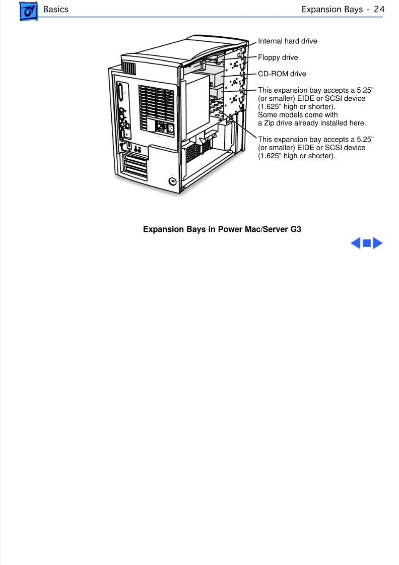
Expansion Bays in Power Mac/Server G3
Floppy drive
CD-ROM drive
This expansion bay accepts a 5.25"(or smaller) EIDE or SCSI device(1.625" high or shorter).Some models come witha Zip drive already installed here.
Internal hard drive
This expansion bay accepts a 5.25"(or smaller) EIDE or SCSI device(1.625" high or shorter).
8/19/2019 Powermac Server g3 Minitower
http://slidepdf.com/reader/full/powermac-server-g3-minitower 41/292
Basics Ultra Wide SCSI Card -
Ultra Wide SCSI CardUltra Wide SCSI support is offered on the Power MacintoshG3 Minitower (optional feature) and G3 Server (standardfeature) via an Ultra Wide SCSI PCI card (p/n 661-2011).
If present, this card is installed in the first PCI slot on thelogic board.
Connecting Additional Internal Devices
If you add an internal drive to the Ultra Wide SCSI bus, youneed to assign it a SCSI ID number in the 8 to 15 range.Devices assigned to numbers 2 through 6 may not work
reliably.
Only internal SCSI devices may be attached to the primaryUltra Wide SCSI card; that is to say, you cannot use theexternal 68-pin connector on the card. To connect external
8/19/2019 Powermac Server g3 Minitower
http://slidepdf.com/reader/full/powermac-server-g3-minitower 42/292
Basics Ultra Wide SCSI Card -
Ultra Wide SCSI devices to the computer, you must install asecond Ultra Wide SCSI card.
To install a second Ultra Wide SCSI card, follow theseguidelines:• Use a single-channel card if possible.• If you need to add a dual-channel Ultra Wide SCSI card,
contact the PCI card vendor to verify compatibility withthe Power Macintosh G3 Minitower and MacintoshServer G3.
• Do not use the Apple Ultra Wide SCSI PCI card (p/n661-2011) as the second card unless it is shipped fromthe factory this way.
Specications for the Ultra Wide SCSI Card
The Ultra Wide SCSI PCI card specifications are as follows:• Automatic termination
8/19/2019 Powermac Server g3 Minitower
http://slidepdf.com/reader/full/powermac-server-g3-minitower 43/292
Basics Ultra Wide SCSI Card -
• Advanced Data Streaming Technology (ADS)• RAID Ready• Embedded RISC I/P processor• Ultra SCSI connector: Fine pitch 68-pin “P”• Flash ROM BIOS
• PCI 2.1 compliant• Large command FIFO• Supports disconnect/reconnect• Asynchronous I/O support• Multiple initiator support• SCSI-3 tagged command queuing• SCSI Manager 4.3 compatible
SCSI-3 Bus
• Adapter interface: Special Bus management hardware forvideo, fileservers, and real-time environments
• Maximum host transfer rate: 133 MB/sec.• Maximum SCSI transfer rates: Synchronous data rate—
8/19/2019 Powermac Server g3 Minitower
http://slidepdf.com/reader/full/powermac-server-g3-minitower 44/292
Basics Ultra Wide SCSI Card -
40 MB/sec. per channel; asynchronous data rate—12 MB/sec.
• SCSI interface: SCSI-1, SCSI-2, SCSI-3, Ultra SCSI• Electrical signals: Single-ended versions• Extensive device support: Up to 105 Through Logical
Unit Numbers (LUN’s) (Wide and Narrow devices)
Cable Length Limits
When using Ultra SCSI single-ended devices, you can connectup to 8 devices if the total cable length is no longer than 1.5meters (about 4.5 feet). If total cable length is between 1.5meters and 3.0 meters (about 9 feet), you can connect only
4 SCSI devices. Error-free operation is not guaranteed ifyou exceed these limits.
When not using Ultra SCSI devices, SCSI specification limitstotal bus cable length for single-ended SCSI to 6 meters or
8/19/2019 Powermac Server g3 Minitower
http://slidepdf.com/reader/full/powermac-server-g3-minitower 45/292
Basics Ultra Wide SCSI Card -
approximately 18 feet (this is a combined figure of bothinternal and external cable lengths). You should keep cablelengths as short as possible to ensure high signal quality andperformance.
If you connect a combination of Wide 16-bit devices andNarrow 8-bit devices on the same connector (notrecommended), Wide devices must be connected first(closest to the connector), followed by the Narrow devices.Refer to the documentation that came with your SCSI devicesto determine if your device is Wide or Narrow, and if it is anUltra SCSI device.
8/19/2019 Powermac Server g3 Minitower
http://slidepdf.com/reader/full/powermac-server-g3-minitower 46/292
Basics 10/100 BaseT Ethernet Card - 30
10/100 BaseT Ethernet CardThe specifications for the 10/100 BaseT ethernet card,which is an optional feature in the G3 Minitower andstandard in the Server G3, are as follows:
• Open Transport: Mac OS 8.1 or later, AppleShare,AppleTalk, NetWare for Macintosh, TCP-IP
• Connector: RJ-45 (for 10BaseT and 100BaseT)• Media, 10BaseT: Cat 3, 4, or 5 UTP on 2 pairs up to
100M• Media, 100BaseT: Cat 5 UTP on 2 pairs up to 100M• Bus interface: PCI revision 2.0 and 2.1, share
interrupt A
• Channel speeds: IEEE Auto Negotiation of 10BaseT and100BaseTX• Communications: IEEE 802.3u 100BaseTX; IEEE 802.3i
10BaseT• Power: 1.2A @ 5V typical
8/19/2019 Powermac Server g3 Minitower
http://slidepdf.com/reader/full/powermac-server-g3-minitower 47/292
Basics 10/100 BaseT Ethernet Card - 31
• Controllers: DECchip 21140, 32-bit internal processorper channel
8/19/2019 Powermac Server g3 Minitower
http://slidepdf.com/reader/full/powermac-server-g3-minitower 48/292
Basics DVD-ROM Drive Technology - 3
DVD-ROM Drive TechnologyDVD stands for Digital Versatile Disc, an audio/video/datastandard based on high-density next-generation opticaldiscs. Through the build-to-order (BTO) program, Apple
Computer offers a DVD-ROM drive (part number 661-1513) and decoder card (part number 661-2071) thattogether are capable of playing DVD-ROM discs.
Warning: DVD discs are much more prone to damage thanCD-ROM discs. Any type of scratch or other abuse mayresult in a disc that is unreadable.
DVD DiscsThe DVD Forum designed several standards for discmanufacture ranging from a single-sided, single-layer discwith 4.7 Gigabytes of data to a double-sided, double-layer
8/19/2019 Powermac Server g3 Minitower
http://slidepdf.com/reader/full/powermac-server-g3-minitower 49/292
Basics DVD-ROM Drive Technology -
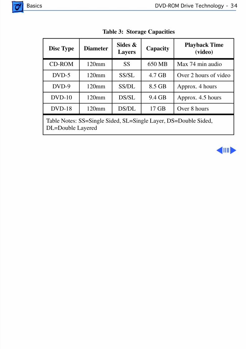
disc with 17 Gigabytes of data stored on the disc.
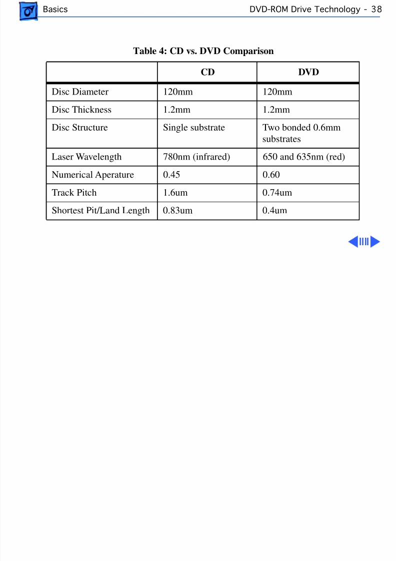
DVD discs can hold nearly 26 times the amount of data thatcan be stored on a conventional CD. This capacity virtuallyeliminates the need to swap discs in the middle of a game orapplication and at the same time reduces the cost and thenumber of discs necessary to hold the data. The followingtable clearly illustrates the difference between CD and DVDstorage possibilities.
8/19/2019 Powermac Server g3 Minitower
http://slidepdf.com/reader/full/powermac-server-g3-minitower 50/292
Basics DVD-ROM Drive Technology -
Table 3: Storage Capacities
Disc Type DiameterSides &Layers Capacity
Playback Time(video)
CD-ROM 120mm SS 650 MB Max 74 min audio
DVD-5 120mm SS/SL 4.7 GB Over 2 hours of video
DVD-9 120mm SS/DL 8.5 GB Approx. 4 hours
DVD-10 120mm DS/SL 9.4 GB Approx. 4.5 hours
DVD-18 120mm DS/DL 17 GB Over 8 hours
Table Notes: SS=Single Sided, SL=Single Layer, DS=Double Sided,DL=Double Layered

8/19/2019 Powermac Server g3 Minitower
http://slidepdf.com/reader/full/powermac-server-g3-minitower 51/292
Basics DVD-ROM Drive Technology -
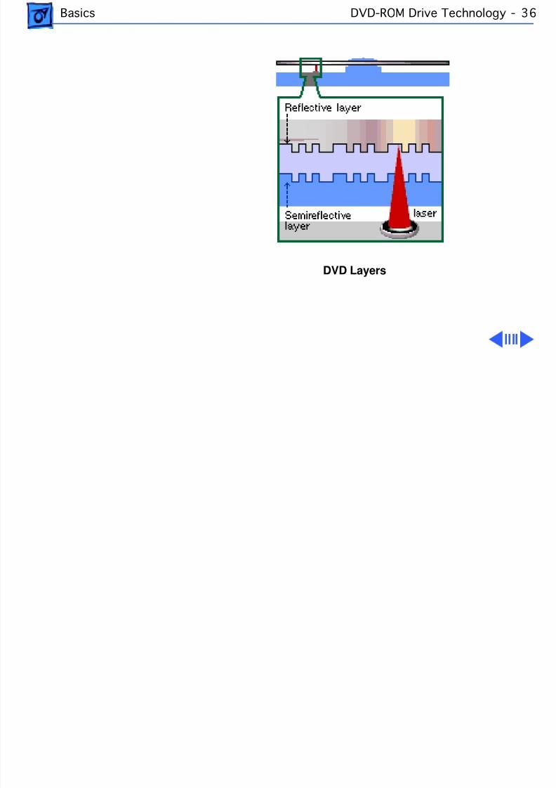
To squeeze all this information onto the CD-sized disc, DVDdisc designers: 1)made track spacing and the pits and landsused to record data nearly half the size of the original CDdesign; 2) made the discs double sided and added another datalayer to each side creating a potential for four layers of data
per disc.The figure below illustrates the layers of a DVD disc.
8/19/2019 Powermac Server g3 Minitower
http://slidepdf.com/reader/full/powermac-server-g3-minitower 52/292
Basics DVD-ROM Drive Technology -
DVD Layers
8/19/2019 Powermac Server g3 Minitower
http://slidepdf.com/reader/full/powermac-server-g3-minitower 53/292
Basics DVD-ROM Drive Technology -
Compared to CD, DVD uses smaller pits and a more closelyspaced track.The result is a significant increase in datadensity. The higher Numerical Aperture (NA) lens of DVDhelps the laser focus on the smaller pits.
Like CD, DVD is 120 mm (4-3/4 inches) in diameter. LikeCD, DVD is 1.2 mm thick composed of (2) 0.6 mmsubstrates bonded together. The new DVD Players will beable to play existing music CDs.
The DVD standard defines a disc that maintains the overalldimensions, look and feel of the current Compact Disc. Someof these similarities will be unmistakable to customersexperiencing DVD for the first time.
8/19/2019 Powermac Server g3 Minitower
http://slidepdf.com/reader/full/powermac-server-g3-minitower 54/292
Basics DVD-ROM Drive Technology -
Table 4: CD vs. DVD Comparison
CD DVD
Disc Diameter 120mm 120mmDisc Thickness 1.2mm 1.2mm
Disc Structure Single substrate Two bonded 0.6mmsubstrates
Laser Wavelength 780nm (infrared) 650 and 635nm (red)
Numerical Aperature 0.45 0.60
Track Pitch 1.6um 0.74um
Shortest Pit/Land Length 0.83um 0.4um
8/19/2019 Powermac Server g3 Minitower
http://slidepdf.com/reader/full/powermac-server-g3-minitower 55/292
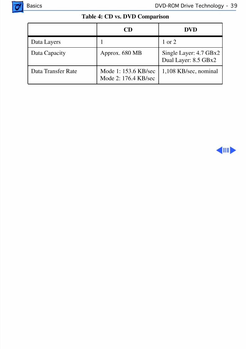
Basics DVD-ROM Drive Technology -
Data Layers 1 1 or 2
Data Capacity Approx. 680 MB Single Layer: 4.7 GBx2Dual Layer: 8.5 GBx2
Data Transfer Rate Mode 1: 153.6 KB/secMode 2: 176.4 KB/sec
1,108 KB/sec, nominal
Table 4: CD vs. DVD Comparison
CD DVD
8/19/2019 Powermac Server g3 Minitower
http://slidepdf.com/reader/full/powermac-server-g3-minitower 56/292
Basics DVD-ROM Drive Technology -
Apple DVD-ROM Drive Specs
The Apple DVD-ROM Drive is an ATAPI drive. It uses an IDEport on the Macintosh for connection to the computer. Beloware some of the specs for the drive. Note that the abovetransfer rate info varies from the data below. The numbersabove reflect the DVD specification where the belownumbers are for the drive that Apple is shipping.
Access Times (including latency)DVD 170 ms or faster typicalCD 100 ms or faster typical
Data CapacityDVD maximum 17 GB 256K Buffer
8/19/2019 Powermac Server g3 Minitower
http://slidepdf.com/reader/full/powermac-server-g3-minitower 57/292
Basics DVD-ROM Drive Technology -
Transfer RateDVD: 2,705 KB/secondCD Mode 1: 1,293 to 3,000 KB/secondCD Mode 2: 1,474 to 3,429 KB/second
Disc Format SupportDVD 9660 Bridge (DVD-ROM Book, DVD-Video Book) Red-Book, Yellow-Book, CD-ROM XA, DA-I Bridge, Photo-CD,Video CD, CD-I Ready, CD-G, Multi-session (Photo-CD, CDExtra)
Note: To be able to play the DVD-Video discs, you must haveinstalled an additional PCI decoder card (part number 661-2071) that will allow the playback of movie discs. This PCIcard contains controllers that decode the MPEG-2 video andDolby AC-3 audio tracks on the movie. Without the card,movies cannot be played. Because of this, the DVD-ROMdrive is only intended for DVD-ROM discs. These are DVDdiscs that contain data just like CDs do currently. If you wish
8/19/2019 Powermac Server g3 Minitower
http://slidepdf.com/reader/full/powermac-server-g3-minitower 58/292
Basics DVD-ROM Drive Technology -
to play DVD Video discs, you will need to purchase a PCIdecoder card.
DVD Software Drivers
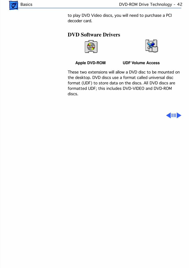
Apple DVD-ROM UDF Volume Access
These two extensions will allow a DVD disc to be mounted onthe desktop. DVD discs use a format called universal discformat (UDF) to store data on the discs. All DVD discs are
formatted UDF; this includes DVD-VIDEO and DVD-ROMdiscs.
8/19/2019 Powermac Server g3 Minitower
http://slidepdf.com/reader/full/powermac-server-g3-minitower 59/292
Basics DVD-ROM Drive Technology -
File Management System Micro UDF & ISO9660
Universal Disc Format (UDF) is a file system standard thatsupports both rewritable and write-once media. It is across-platform data format that allows transparentinterchange of data via optical discs or CD-ROMs. UDF alsodefines methods for reading, writing and other operations.Discs that are read on a Mac OS-based computer may also beread on a DOS, UNIX or Windows based computer. The formatcan coexist with CD-ROM data format (ISO 9660) but alsoincorporates the International Standards Organizationinterchange standard for rewritable and write-once media(ISO 13346) thus providing support for CD-Recordablediscs (CD-R).
Before UDF was available, every CD-Recordable drive used aproprietary format of writing data, which prevents theability to interchange files. Fortunately, most drives
8/19/2019 Powermac Server g3 Minitower
http://slidepdf.com/reader/full/powermac-server-g3-minitower 60/292
Basics DVD-ROM Drive Technology -
supported either software or hardware updates to allow thedrive to be upgraded so that it could write UDF. The firstgeneration of DVD drives could not read CD-R media and insome cases actually damaged the media.
UDF Features• Enables operating system independent interchange on
optical media.• Designed to support the massive capacities of optical
jukeboxes.• Only ISO standard file system for WORM media (Write
Once Read Many).• Industry selected file system for second generation (high
capacity) CD-ROM.• Industry selected file system for DVD.• Enables full interchange between computer-based and
entertainment-based media.• Endorsed by world leading optical manufacturers.
8/19/2019 Powermac Server g3 Minitower
http://slidepdf.com/reader/full/powermac-server-g3-minitower 61/292
Basics DVD-ROM Drive Technology -
Stand-alone players use UDF while computer applicationsuse the UDF bridge format, which consists of both ISO-9660CD-ROM format and UDF.
8/19/2019 Powermac Server g3 Minitower
http://slidepdf.com/reader/full/powermac-server-g3-minitower 62/292
Basics FireWire Technology - 4
FireWire TechnologyThis section explains what FireWire technology is and givesspecific information on Apple Computer’s FireWire card,which ships as an optional build-to-order module on the
Power Macintosh G3 Minitower.
FireWire Dened
FireWire technology refers to Apple Computer’s cross-platform implementation of the high-speed serial data bus(defined by IEEE Standard 1394-1995) that can move largeamounts of data between computers and peripheral devices.
FireWire is:
• A digital interface - no need to convert digital data intoanalog for better signal integrity
8/19/2019 Powermac Server g3 Minitower
http://slidepdf.com/reader/full/powermac-server-g3-minitower 63/292
Basics FireWire Technology - 4
• A physically small thin serial cable - replaces today'sbulky and expensive interfaces
• Easy to use - no need for terminators, device IDs,screws, or complicated set-ups
• Hot pluggable - devices can be added and removed while
the bus is active• Scalable - the Standard defines 100, 200, and 400Mbps devices and can support the multiple speeds on asingle bus
• Flexible - the Standard supports freeform daisychaining and branching for peer-to-peerimplementations
• Fast, guaranteed bandwidth - the Standard supportsguaranteed delivery of time critical data which enablessmaller buffers (lower cost)
• Non-proprietary - no licensing problems, adoption isencouraged
8/19/2019 Powermac Server g3 Minitower
http://slidepdf.com/reader/full/powermac-server-g3-minitower 64/292
Basics FireWire Technology - 4
FireWire technology speeds up the movement of multimediadata and large files and enables the connection of digitalconsumer products -- including digital camcorders, digitalvideo tapes, digital video disks, set-top boxes, and musicsystems -- directly to a personal computer.
Devices can be connected in any combination of branchingand chaining, as long as no loops are formed. A FireWire buscan support up to 16 consecutive cable hops of 4.5 meterseach. There are no SCSI-style ID numbers to set and notermination requirements.
FireWire supports two types of data transfer: asynchronousand isochronous. For traditional computer memory-mapped,
load and store applications, asynchronous transfer isappropriate and adequate; but, one of FireWire's keyfeatures is its support of isochronous data channels.

8/19/2019 Powermac Server g3 Minitower
http://slidepdf.com/reader/full/powermac-server-g3-minitower 65/292
Basics FireWire Technology - 4
Isochronous data transfer provides guaranteed datatransport at a pre-determined rate. This is especiallyimportant for multimedia applications where uninterruptedtransport of time-critical data and just-in-time deliveryreduce the need for costly buffering. This leads to perhaps
one of the most important uses of FireWire as the digitalinterface for consumer electronics and AV peripherals.
FireWire is a peer-to-peer interface. This allows dubbingfrom one camcorder to another without a computer. It alsoallows multiple computers to share a given peripheralwithout any special support in the peripheral or thecomputers. It is a result of all of these features thatFireWire has become the digital interface of choice and itsacceptance is growing.
In the world of video editing, FireWire enabled camerasremove the need for costly analog video computer frame
8/19/2019 Powermac Server g3 Minitower
http://slidepdf.com/reader/full/powermac-server-g3-minitower 66/292
Basics FireWire Technology - 5
buffers to capture digital video. FireWire will graduallyimprove upon existing interfaces such as SCSI. FireWireprovides higher speed, lower cost, and is more user friendlythan most existing interfaces. SCSI products such asscanners, CDROMs, disk drives, and printers are already
evaluating when they will move to FireWire.FireWire has the bandwidth capacity to replace andconsolidate most other peripheral connection communicationmethods in use today. Hot plugging, power sourcing, anddynamic reconfiguration make FireWire a user-friendlyalternative to today's interconnects. These features willallow "plugging in" of computer peripherals as easily asplugging in a home appliance.
The Apple FireWire Digital Video Camera Card
The optional Apple FireWire Digital Video Camera (DVC)
8/19/2019 Powermac Server g3 Minitower
http://slidepdf.com/reader/full/powermac-server-g3-minitower 67/292
Basics FireWire Technology - 5
card is Apple Computer’s first implementation of FireWiretechnology. This card is designed to work with digital videocamcorders and decks that use the DV format and have aFireWire port (sometimes marked IEEE 1394 or DV IN/OUT).
The FireWire DVC hardware and software, together with anon-linear editing application, allow the user to capture DVmovie clips to their hard disk. They can view the clips inMoviePlayer or other QuickTime 3.0 applications, and editand render the DV movies.
If the user has a video editing application with an exportfunction, they can send (print or record) movies back to the
tape in their camcorder or deck. The software also allows theFireWire device to be controlled from the computer.
The Apple FireWire DVC card installs in any available PCIslot on the Power Mac/Server G3 logic board. It operates at
8/19/2019 Powermac Server g3 Minitower
http://slidepdf.com/reader/full/powermac-server-g3-minitower 68/292
Basics FireWire Technology - 5
200 Mbps and supports a single digital video camera. Theexternal FireWire cable, which ships with the card,connects any one of the 6-pin, external connectors on thecard to a 4-pin connector on the digital video camera.
The Apple FireWire Card is designed to keep the networkalive even if the Macintosh is shut down. Loss of power to theMacintosh will not affect the operation of a FireWire card aslong as it can draw power from other cards on the bus. Eachcard provides power which is available to other devices onthe network. This means that a system shutdown will notresult in interrupted transmission over a FireWirenetwork.
Important: For more information about cable managementand power issues, please refer to the FireWire ReadMe fileon the FireWire CD.
8/19/2019 Powermac Server g3 Minitower
http://slidepdf.com/reader/full/powermac-server-g3-minitower 69/292
Basics FireWire Technology - 5
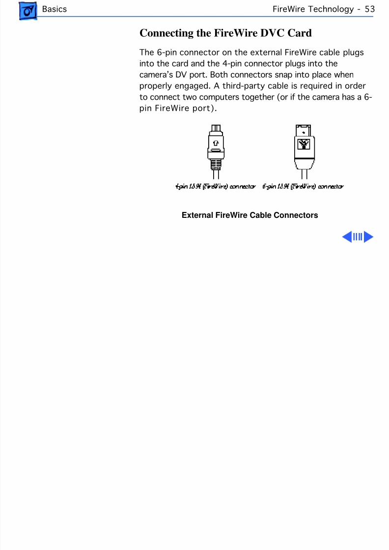
Connecting the FireWire DVC Card
The 6-pin connector on the external FireWire cable plugsinto the card and the 4-pin connector plugs into thecamera’s DV port. Both connectors snap into place whenproperly engaged. A third-party cable is required in orderto connect two computers together (or if the camera has a 6-pin FireWire port).
External FireWire Cable Connectors
8/19/2019 Powermac Server g3 Minitower
http://slidepdf.com/reader/full/powermac-server-g3-minitower 70/292
Basics FireWire Technology - 5
Installing the FireWire Card Software
To install the Apple FireWire Card software:
1 Insert the FireWire CD.
2 Double-click the Installer icon.
3 Follow the on-screen instructions.
4 Restart the computer.
Important: An extension called FireWire Support may belocated in a folder titled FireWire in the Apple Extras folderon the Macintosh. Do not move this older extension to theExtensions folder, as it may interfere with the operation of
the new Apple FireWire software.
8/19/2019 Powermac Server g3 Minitower
http://slidepdf.com/reader/full/powermac-server-g3-minitower 71/292
Basics The DDS-3 Tape Drive - 5
The DDS-3 Tape DriveThe Power Macintosh G3 Minitower and Macintosh ServerG3 offer a DDS-3 tape drive as a build-to-order option.This internal DDS-3 tape backup drive and accompanying
software can perform full or partial backup and restoreprocedures for all of the data on the computer’s hard drives.
In addition, the tape drive automatically performs errorcorrection and data compression of the files that are backedup and restored.The error-correction feature helps ensurea high level of data integrity. The data-compression featureallows more data to fit on a cassette than do conventionalbackup mechanisms.
The DDS-3 tape drive is fully compatible with tapes inDDS-3, DDS-2, DDS, and DDS-DC format. For bestperformance, customer’s should use Sony Digital Data
8/19/2019 Powermac Server g3 Minitower
http://slidepdf.com/reader/full/powermac-server-g3-minitower 72/292
Basics The DDS-3 Tape Drive - 5
Storage (DDS) computer-grade tape, part number DGD125P, with 12 GB capacity (125 meters/410 feet). Onceyou insert a tape, it takes about 24 seconds for it to load.When you eject a tape, it takes about 20 seconds for it tounload.
The DDS-3 tape drive comes with a cleaning cassette thatcustomers should use to clean the tape-drive heads. Theintervals at which the tape drive should be cleaned dependson how often it is used. In general, if backups are performeddaily, the tape drive should be cleaned weekly. If backupsare performed weekly, the tape drive should be cleaned oncea month. The tape drive should also be cleaned when thestatus light shows a Flash-2 pattern. Status lights aredescribed in the next section.
When the cleaning cassette is inserted into the drive, thedrive automatically loads it and cleans the heads. When the
8/19/2019 Powermac Server g3 Minitower
http://slidepdf.com/reader/full/powermac-server-g3-minitower 73/292
Basics The DDS-3 Tape Drive - 5
cleaning process is completed, the drive automaticallyejects the cassette.
Customers are advised to keep a record of how many timesthey use the cleaning cassette. After 25 uses, it should bereplaced. (For best results, use Sony part numberDG5CL/2.)
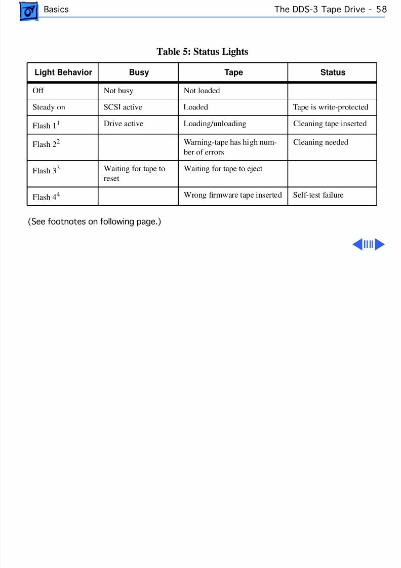
Status Lights
Underneath the tape drive opening are three lights thatinform you of the status of tape operations. The lights arelabeled (left to right) Busy, Tape, and Status. The followingtable lists what a light indicates when it is on, off, orflashing a pattern.
8/19/2019 Powermac Server g3 Minitower
http://slidepdf.com/reader/full/powermac-server-g3-minitower 74/292
Basics The DDS-3 Tape Drive - 5
(See footnotes on following page.)
Table 5: Status Lights
Light Behavior Busy Tape Status
Off Not busy Not loadedSteady on SCSI active Loaded Tape is write-protected
Flash 1 1 Drive active Loading/unloading Cleaning tape inserted
Flash 2 2 Warning-tape has high num-ber of errors
Cleaning needed
Flash 3 3 Waiting for tape toreset
Waiting for tape to eject
Flash 4 4 Wrong rmware tape inserted Self-test failure
8/19/2019 Powermac Server g3 Minitower
http://slidepdf.com/reader/full/powermac-server-g3-minitower 75/292
Basics The DDS-3 Tape Drive - 5
1 Flash 1 - the light flashes .25 seconds on, .25 seconds off.
2 Flash 2 - the light flashes 3.5 seconds on, .5 seconds off.
3 Flash 3 - the light flashes .25 seconds on, one second off.
4 Flash 4 - the light flashes twice every 1.25 seconds.
8/19/2019 Powermac Server g3 Minitower
http://slidepdf.com/reader/full/powermac-server-g3-minitower 76/292
Basics The DDS-3 Tape Drive - 6
Operating Environment
The tape drive will not operate properly in high humidity.Be sure to adhere to the environmental requirements for theserver described in the technical information that came withthe computer. In addition, follow the recommendations foruse that came with the tape cassette.
Follow these guidelines to avoid temperature problems:– Avoid exposing cassettes to extreme heat or cold. For
example, don’t store a cassette in a car in brightsunlight.
– Avoid transferring data to or from a tape cassette whenthe temperature is changing by more than 10 degrees F
per hour (roughly 5 degrees C per hour).
8/19/2019 Powermac Server g3 Minitower
http://slidepdf.com/reader/full/powermac-server-g3-minitower 77/292
Basics The Cuda Chip -
The Cuda ChipThe Cuda is a microcontroller chip. Its function is to• Turn system power on and off• Manage system resets from various commands
• Maintain parameter RAM (PRAM)• Manage the Apple Desktop Bus (ADB)• Manage the real-time clock
Many system problems can be resolved by resetting the Cudachip (see Symptom Charts for examples). Press the Cudareset button on the logic board to reset the Cuda chip. (TheCuda reset button is at the edge of the logic board near thePCI slots. See “Logic Board Diagram” later in this chapter.)If you continue to experience system problems, refer to“Resetting the Logic Board” in this Basics chapter.
8/19/2019 Powermac Server g3 Minitower
http://slidepdf.com/reader/full/powermac-server-g3-minitower 78/292
Basics Resetting the Logic Board - 62
Resetting the Logic BoardResetting the logic board can resolve many system problems(refer to “Symptom Charts” for examples). Whenever youhave a unit that fails to power up, you should follow this
procedure before replacing any modules.1 Unplug the computer.
2 Remove the battery from the logic board.
3 Disconnect the power supply cable from the logic boardand then press the Power On button. (See “Logic BoardDiagram” later in this chapter to locate the Power Onbutton.)
4 Wait at least 10 minutes before replacing the battery.
5 Make sure the battery is installed in the correct +/-direction.

8/19/2019 Powermac Server g3 Minitower
http://slidepdf.com/reader/full/powermac-server-g3-minitower 79/292
Basics Resetting the Logic Board - 63
6 Reassemble the computer and test the unit.
Note: This procedure resets the computer’s PRAM. Be sureto check the computer’s time/date and other systemparameter settings afterwards.
8/19/2019 Powermac Server g3 Minitower
http://slidepdf.com/reader/full/powermac-server-g3-minitower 80/292
Basics Sound -
SoundThe sound system for the Power Macintosh/Server G3computers is implemented entirely on the I/O cards (thereare two versions available for the Power Macintosh G3 and
one available for the Macintosh Server G3). The I/O cardssupport 16-bit stereo sound output and input, availablesimultaneously.
The sound circuitry on the I/O cards and system softwarecan create sounds digitally and either play the soundsthrough speakers inside the enclosure or send the soundsignals out through the sound output jacks. The soundcircuitry digitizes and records sound as 16-bit samples. Thecomputer can use 11.025K, or 22.050K, or 44.100Ksamples per second. The sound system plays samples at thesampling rate specified in the Monitors & Sound controlpanel.

8/19/2019 Powermac Server g3 Minitower
http://slidepdf.com/reader/full/powermac-server-g3-minitower 81/292
Basics Sound -
The Power Macintosh G3 also records sound from severalsources:• A microphone connected to the line-level sound input
jack• The sound-in ports on the video input module
• Analog sound from optional communications cards• A compact disc in the CD-ROM player• Analog sound from the cross-platform card in a PCI slot
With each sound input source, sound playthrough can beenabled or disabled.
8/19/2019 Powermac Server g3 Minitower
http://slidepdf.com/reader/full/powermac-server-g3-minitower 82/292
Basics Sound -
Sound Output
All sound output features for the Power Macintosh/ServerG3 computer are provided by an I/O card. The Audio I/O cardprovides one mini jack for sound output on the back of theenclosure. The AV I/O card (not available for the MacintoshServer G3) provides three sound output connectors—twoRCA jacks for right and left sound out, and one 1/8-inchmini jack for a stereophonic phone plug.
The output jacks are connected to the sound amplifier. Themini jack is intended for connecting a pair of headphones oramplified external speakers. There is one built-in speaker.Inserting a plug into the sound output mini jack disconnects
the internal speaker.
8/19/2019 Powermac Server g3 Minitower
http://slidepdf.com/reader/full/powermac-server-g3-minitower 83/292
Basics Sound -
Sound Input
The I/O cards provide a stereo sound input jack on the backof the enclosure for connecting an external Apple PlainTalkline-level microphone (not standard equipment on theMacintosh Server G3) or other sound source pair of line-level signals. The sound input jack accepts a standard 1/8-inch stereophonic phone plug (two signals plus ground).
Note: The microphone for the Macintosh LC and LC II doesnot work with the I/O cards.
The AV I/O card provides an additional pair of RCA jacks forright and left sound input for an external source, such as a
TV, VCR, or VTR.Options in the Monitors & Sound control panel determine theinteraction between the sound input and output devices. Thesound circuitry normally operates in one of three modes:

8/19/2019 Powermac Server g3 Minitower
http://slidepdf.com/reader/full/powermac-server-g3-minitower 84/292
Basics Sound -
• Sound playback—computer-generated sound is sent to thespeaker and the sound output jacks.
• Sound playback with playthrough—computer sound andsound input are mixed and sent to the speakers and soundoutput jacks.
• Sound record with playthrough—input sound is recordedand also sent to the speakers and sound output jacks.
8/19/2019 Powermac Server g3 Minitower
http://slidepdf.com/reader/full/powermac-server-g3-minitower 85/292
Basics Video Input and Output - 69
Video Input and OutputThe AV I/O card (not available for the Macintosh Server G3)supports video input and output of composite and S-videosignals. The card supports input and output of NTSC, PAL,
and SECAM video formats.
The AV I/O card accepts video from an external source anddisplays it in a window on the computer’s display. Thefeatures of the video portion of the card include:
• Video display in a 320 X 240 pixel window• Pixel expansion for 640 X 480 pixel maximum display• Video overlay capability• YUV format for digital video input• A bi-directional digital audio video (DAV) connector for
adding a video processor on a PCI expansion card
8/19/2019 Powermac Server g3 Minitower
http://slidepdf.com/reader/full/powermac-server-g3-minitower 86/292
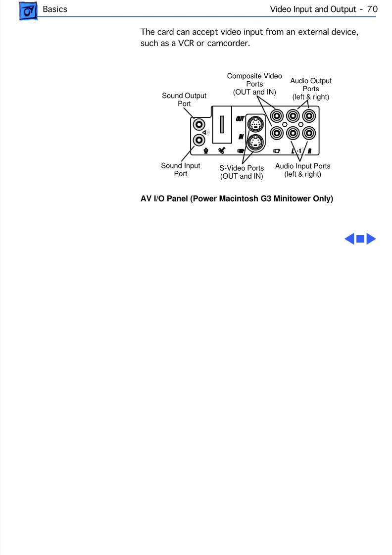
Basics Video Input and Output - 70
The card can accept video input from an external device,such as a VCR or camcorder.
AV I/O Panel (Power Macintosh G3 Minitower Only)
Audio Output
Ports(left & right)
Audio Input Ports(left & right)
Sound OutputPort
Sound InputPort
S-Video Ports(OUT and IN)
Composite VideoPorts
(OUT and IN)
8/19/2019 Powermac Server g3 Minitower
http://slidepdf.com/reader/full/powermac-server-g3-minitower 87/292
Basics Running a G3 Server without a Monitor - 71
Running a G3 Server without a MonitorYou can use software such as the Apple NetworkAdministrator Toolkit and a video terminator (p/n 922-3470) to run the G3 Server remotely from another
computer, thereby allowing you to disconnect the monitorattached to the Server.
To run the Macintosh Server G3 without a monitor:
1 Follow the instructions in the “Setting Up Your Server”manual to set up the server, including connecting amonitor, mouse, and keyboard.
2 Follow the instructions in the “Macintosh ServerAdministration” manual to configure the server. Be surethe server is up and running and that network servicesare operating properly.
3 Turn off the server and then disconnect the monitor.

8/19/2019 Powermac Server g3 Minitower
http://slidepdf.com/reader/full/powermac-server-g3-minitower 88/292
Basics Running a G3 Server without a Monitor - 72
4 Attach a video terminator to the monitor port on the backpanel of the server and then turn on the server again.
5 Follow the instructions that came with the remote accesssoftware for logging in to and controlling the server.
Note: If you want to connect a monitor at a later time, youmust turn off the server before you connect the monitor.
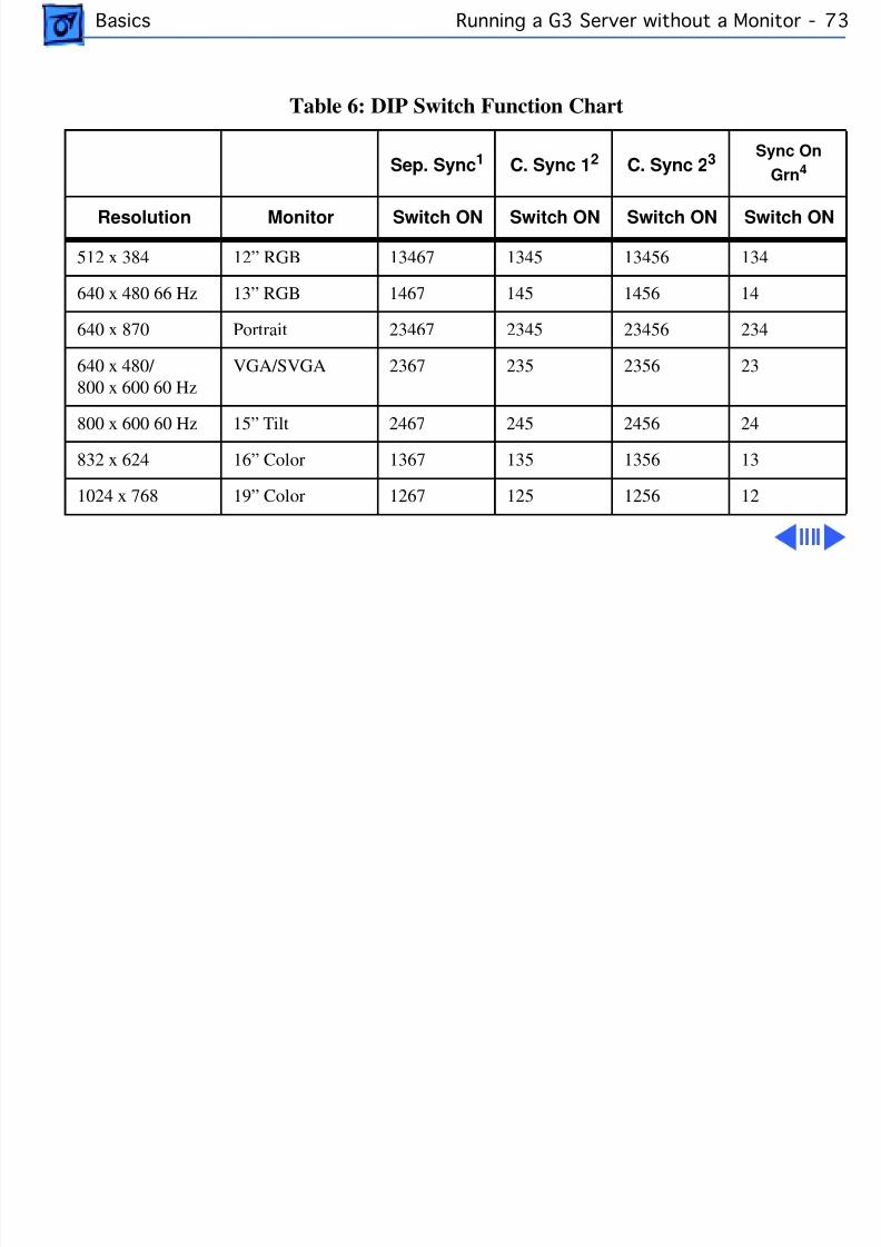
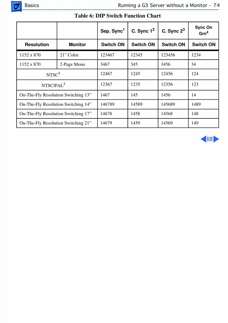
The table on the following page explains the DIP switchfunctions for the video terminator.
8/19/2019 Powermac Server g3 Minitower
http://slidepdf.com/reader/full/powermac-server-g3-minitower 89/292
Basics Running a G3 Server without a Monitor - 73
Table 6: DIP Switch Function Chart
Sep. Sync 1 C. Sync 1 2 C. Sync 2 3 Sync OnGrn 4
Resolution Monitor Switch ON Switch ON Switch ON Switch ON
512 x 384 12” RGB 13467 1345 13456 134
640 x 480 66 Hz 13” RGB 1467 145 1456 14
640 x 870 Portrait 23467 2345 23456 234
640 x 480/ 800 x 600 60 Hz
VGA/SVGA 2367 235 2356 23
800 x 600 60 Hz 15” Tilt 2467 245 2456 24
832 x 624 16” Color 1367 135 1356 13
1024 x 768 19” Color 1267 125 1256 12
8/19/2019 Powermac Server g3 Minitower
http://slidepdf.com/reader/full/powermac-server-g3-minitower 90/292
Basics Running a G3 Server without a Monitor - 74
1152 x 870 21” Color 123467 12345 123456 1234
1152 x 870 2-Page Mono 3467 345 3456 34
NTSC 5 12467 1245 12456 124
NTSC/PAL 5 12367 1235 12356 123
On-The-Fly Resolution Switching 13” 1467 145 1456 14
On-The-Fly Resolution Switching 14” 146789 14589 145689 1489
On-The-Fly Resolution Switching 17” 14678 1458 14568 148
On-The-Fly Resolution Switching 21” 14679 1459 14569 149
Table 6: DIP Switch Function Chart
Sep. Sync 1 C. Sync 1 2 C. Sync 2 3 Sync OnGrn 4
Resolution Monitor Switch ON Switch ON Switch ON Switch ON
8/19/2019 Powermac Server g3 Minitower
http://slidepdf.com/reader/full/powermac-server-g3-minitower 91/292
Basics Running a G3 Server without a Monitor - 75
Notes for Table 3:1 Sep. Sync: denotes Separate Synchronization.2 C. Sync 1: denotes Composite Synchronization Type 1(DB15 Pin 3 connected to HD15 Pin 13).3 C. Sync 2: denotes Composite Synchronization Type 2
(DB15 Pin 3 & 15 connected to HD15 Pin 13).4 Sync On Grn: denotes Synchronization on Green.
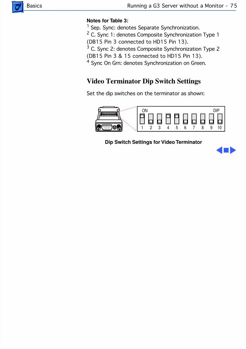
Video Terminator Dip Switch Settings
Set the dip switches on the terminator as shown:
Dip Switch Settings for Video Terminator
ON DIP
1 2 3 4 5 6 7 8 9 10
1
ON DIP
2 3 4 5 6 7 8 9 10
8/19/2019 Powermac Server g3 Minitower
http://slidepdf.com/reader/full/powermac-server-g3-minitower 92/292
Basics The DAV Connector - 7
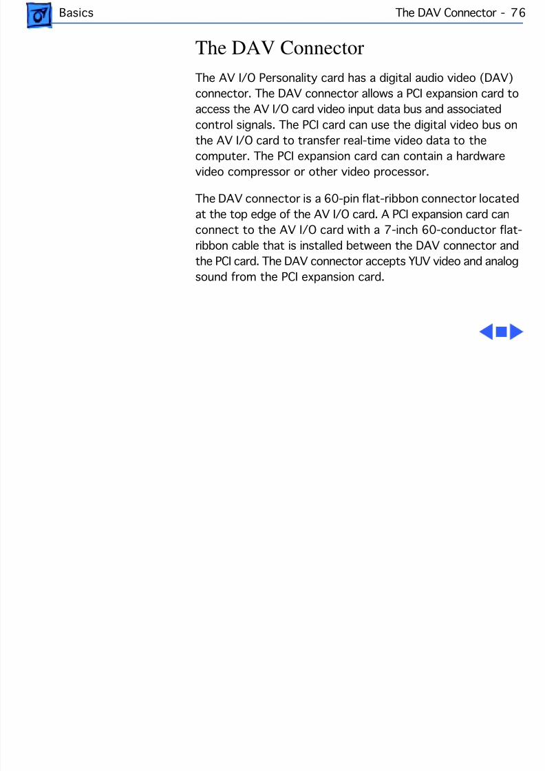
The DAV ConnectorThe AV I/O Personality card has a digital audio video (DAV)connector. The DAV connector allows a PCI expansion card toaccess the AV I/O card video input data bus and associated
control signals. The PCI card can use the digital video bus onthe AV I/O card to transfer real-time video data to thecomputer. The PCI expansion card can contain a hardwarevideo compressor or other video processor.
The DAV connector is a 60-pin flat-ribbon connector locatedat the top edge of the AV I/O card. A PCI expansion card canconnect to the AV I/O card with a 7-inch 60-conductor flat-ribbon cable that is installed between the DAV connector andthe PCI card. The DAV connector accepts YUV video and analogsound from the PCI expansion card.
8/19/2019 Powermac Server g3 Minitower
http://slidepdf.com/reader/full/powermac-server-g3-minitower 93/292
Basics Voltage Switch - 7
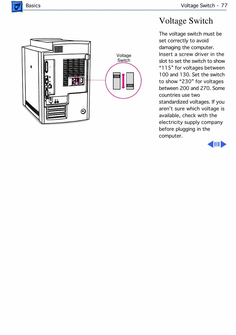
Voltage SwitchThe voltage switch must beset correctly to avoiddamaging the computer.
Insert a screw driver in theslot to set the switch to show“115” for voltages between100 and 130. Set the switchto show “230” for voltagesbetween 200 and 270. Somecountries use twostandardized voltages. If you
aren’t sure which voltage isavailable, check with theelectricity supply companybefore plugging in thecomputer.
VoltageSwitch
8/19/2019 Powermac Server g3 Minitower
http://slidepdf.com/reader/full/powermac-server-g3-minitower 94/292
Basics Voltage Switch - 7
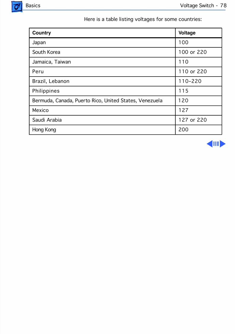
Here is a table listing voltages for some countries:
Country Voltage
Japan 100
South Korea 100 or 220
Jamaica, Taiwan 110
Peru 110 or 220
Brazil, Lebanon 110–220
Philippines 115
Bermuda, Canada, Puerto Rico, United States, Venezuela 120
Mexico 127Saudi Arabia 127 or 220
Hong Kong 200
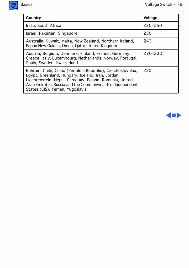
8/19/2019 Powermac Server g3 Minitower
http://slidepdf.com/reader/full/powermac-server-g3-minitower 95/292
Basics Voltage Switch - 7
India, South Africa 220–250
Israel, Pakistan, Singapore 230
Australia, Kuwait, Malta, New Zealand, Northern Ireland,Papua New Guinea, Oman, Qatar, United Kingdom
240
Austria, Belgium, Denmark, Finland, France, Germany,Greece, Italy, Luxembourg, Netherlands, Norway, Portugal,Spain, Sweden, Switzerland
220–230
Bahrain, Chile, China (People’s Republic), Czechoslovakia,Egypt, Greenland, Hungary, Iceland, Iran, Jordan,Liechtenstein, Nepal, Paraguay, Poland, Romania, UnitedArab Emirates, Russia and the Commonwealth of IndependentStates (CIS), Yemen, Yugoslavia
220
Country Voltage
8/19/2019 Powermac Server g3 Minitower
http://slidepdf.com/reader/full/powermac-server-g3-minitower 96/292
Basics PowerPC G3 and Backside Cache - 80
PowerPC G3 and Backside CacheBackside cache is a significant architectural design changefrom earlier PowerPC processors. The main advantage of thebackside cache architecture is the speed of the dedicated
CPU-to-L2 cache interface. Using the dedicated bus allowsthe CPU to access the fast L2 cache storage through a highspeed bus without addressing the slower system bus orcompeting with other devices attached to the system bus. Incomparison, a “far-side” cache running on the system buswould limit that SRAM interface to 50MHz.
The PowerPC G3 microprocessor interfaces with SRAMstorage via a dedicated bus running at various multiples ofthe core PLL CPU speed. With high speed L2 SRAM and adedicated L2 bus, the CPU can access stored information upto the speed of the processor clock. L2 access is determinedby the clock ratio setting. For example, with a 250MHz
8/19/2019 Powermac Server g3 Minitower
http://slidepdf.com/reader/full/powermac-server-g3-minitower 97/292
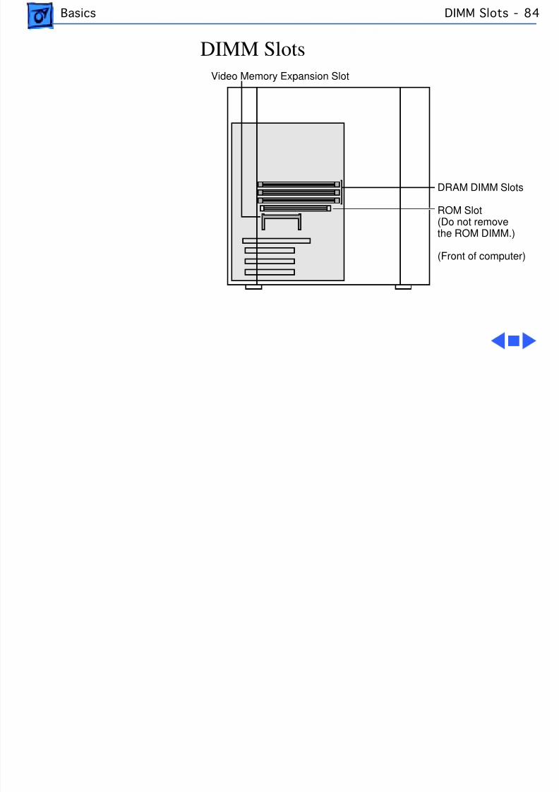
Basics SDRAM DIMMs
PowerPC G3, and a 2.5 L2 bus ratio, the backside cache busspeed will be 100MHz, twice the speed of the system bus.
SDRAM DIMMsThree DRAM expansion slots on the logic board accept 3.3 VSDRAM unbuffered 8-byte DIMMs. The 168-pin DIMM has a64-bit-wide data bus per bank. The minimum bank sizesupported is 2 MB, and the largest is 64 MB. The largestDIMM supported is a two-bank DIMM of 128 MB using 64Mbit SDRAM devices. The minitower chassis on the PowerMacintosh G3 and Macintosh Server G3 accommodates a RAMDIMM height of 1.15 inches.
The DRAM DIMMs can be installed one or more at a time. Thelogic board supports only linear memory organization.Therefore, no performance gains are seen when two DIMMs
8/19/2019 Powermac Server g3 Minitower
http://slidepdf.com/reader/full/powermac-server-g3-minitower 98/292
Basics SGRAM Video Memory -
of the same size are installed. Any supported size DIMM canbe installed in any DIMM slot, and the combined memory ofall the DIMMs installed will be configured as a contiguousarray of memory.
Important: Power Mac/Server G3 computers use SDRAMDIMMs. DIMMs from older Macintosh computers are notcompatible and should not be used even though they fit intothe Power Mac/Server G3 DRAM DIMM slots.
SGRAM Video MemoryThe Power Mac/Server G3 logic board comes with 2 MB of
Synchronous Graphic RAM (SGRAM) video memory solderedon. The logic board also contains a video memory expansionslot that accepts a Small Outline DIMM (SO-DIMM) toincrease video memory up to a maximum of 6 MB. Apple

8/19/2019 Powermac Server g3 Minitower
http://slidepdf.com/reader/full/powermac-server-g3-minitower 99/292
Basics SGRAM Video Memory -
supports a 4 MB SGRAM SO-DIMM that is 32-bit wide,144-pin, fast-paged, 83 MHz/12 ns cycle time or faster.
Important: Use only SGRAM SO-DIMMs. Never use the 256Kor 512K video memory DIMMs used in older computers.
8/19/2019 Powermac Server g3 Minitower
http://slidepdf.com/reader/full/powermac-server-g3-minitower 100/292
Basics DIMM Slots -
DIMM Slots
ROM Slot(Do not removethe ROM DIMM.)
DRAM DIMM Slo
Video Memory Expansion Slot
(Front of computer
8/19/2019 Powermac Server g3 Minitower
http://slidepdf.com/reader/full/powermac-server-g3-minitower 101/292
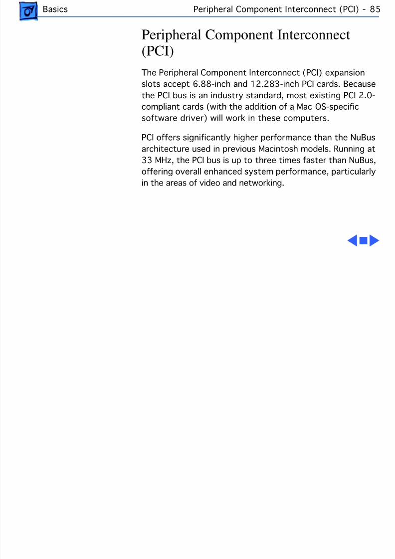
Basics Peripheral Component Interconnect (PCI) - 85
Peripheral Component Interconnect(PCI)The Peripheral Component Interconnect (PCI) expansionslots accept 6.88-inch and 12.283-inch PCI cards. Becausethe PCI bus is an industry standard, most existing PCI 2.0-compliant cards (with the addition of a Mac OS-specificsoftware driver) will work in these computers.
PCI offers significantly higher performance than the NuBusarchitecture used in previous Macintosh models. Running at33 MHz, the PCI bus is up to three times faster than NuBus,offering overall enhanced system performance, particularly
in the areas of video and networking.
8/19/2019 Powermac Server g3 Minitower
http://slidepdf.com/reader/full/powermac-server-g3-minitower 102/292
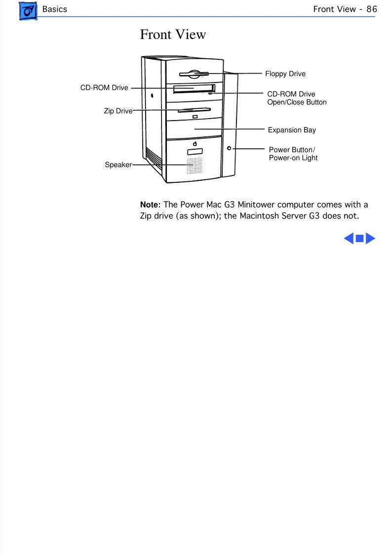
Basics Front View -
Front View
Note: The Power Mac G3 Minitower computer comes with aZip drive (as shown); the Macintosh Server G3 does not.
Floppy Drive
CD-ROM Drive
Expansion Bay
Zip Drive
Power Button/ Power-on Light
CD-ROM DriveOpen/Close Button
Speaker
8/19/2019 Powermac Server g3 Minitower
http://slidepdf.com/reader/full/powermac-server-g3-minitower 103/292
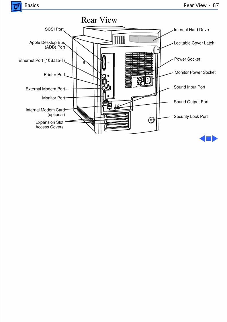
Basics Rear View -
Rear ViewInternal Hard Drive
Lockable Cover Latc
Sound Input Port
SCSI Port
Apple Desktop Bus(ADB) Port
Sound Output Port
Internal Modem Card(optional)
Monitor Power Sock
Security Lock Port
External Modem Port
Printer Port
Ethernet Port (10Base-T)
Monitor Port
Expansion SlotAccess Covers
Power Socket
8/19/2019 Powermac Server g3 Minitower
http://slidepdf.com/reader/full/powermac-server-g3-minitower 104/292
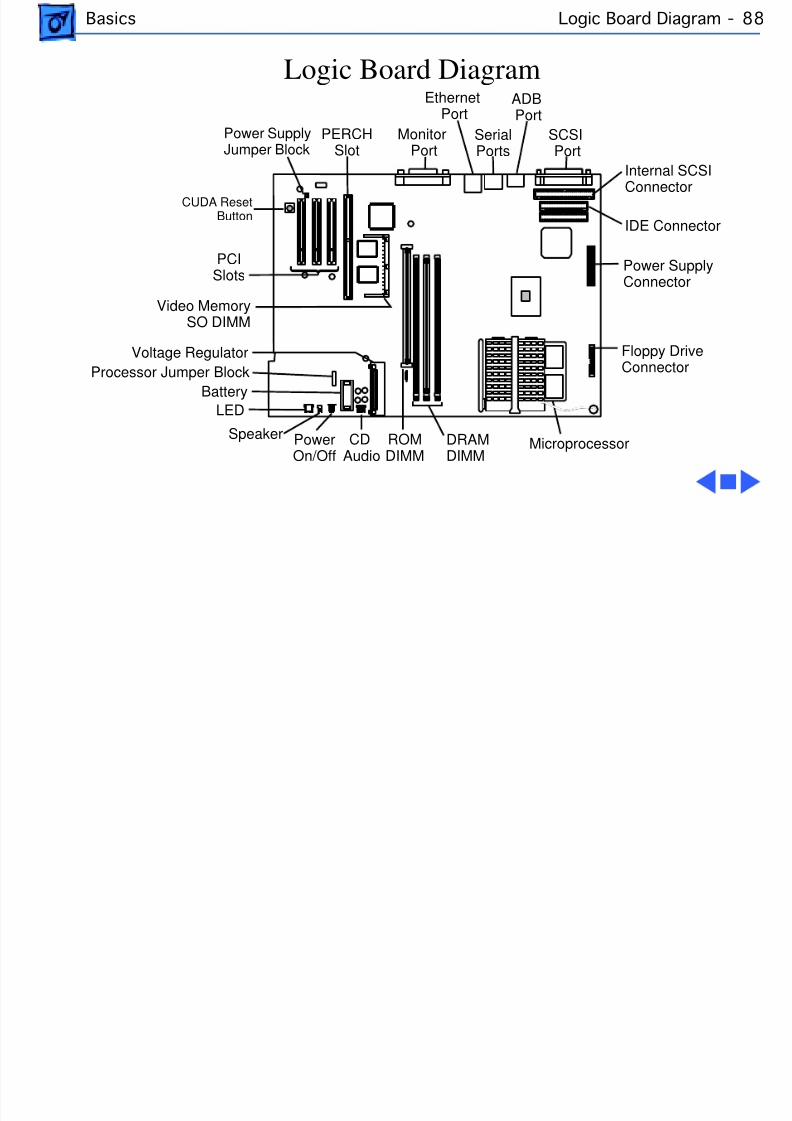
Basics Logic Board Diagram - 8
Logic Board Diagram
PCISlots
Battery
ROMDIMM
PERCHSlot
Internal SCSIConnector
Speaker CDAudio
Floppy Drive
Connector
Power SupplyConnector
Voltage Regulator
LED
SCSIPort
ADB Port
SerialPorts
EthernetPort
MonitorPort
IDE Connector
MicroprocessorDRAMDIMM
PowerOn/Off
Video MemorySO DIMM
Processor Jumper Block
Power SupplyJumper Block
CUDA ResetButton
8/19/2019 Powermac Server g3 Minitower
http://slidepdf.com/reader/full/powermac-server-g3-minitower 105/292
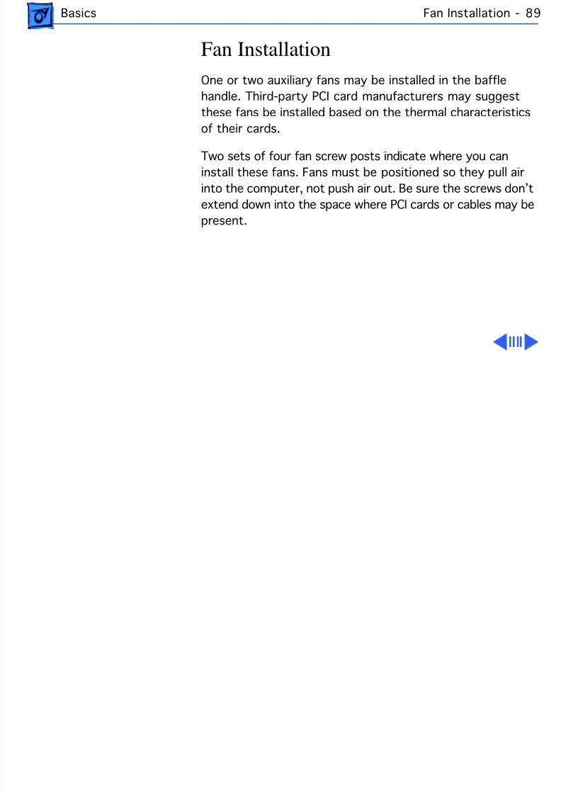
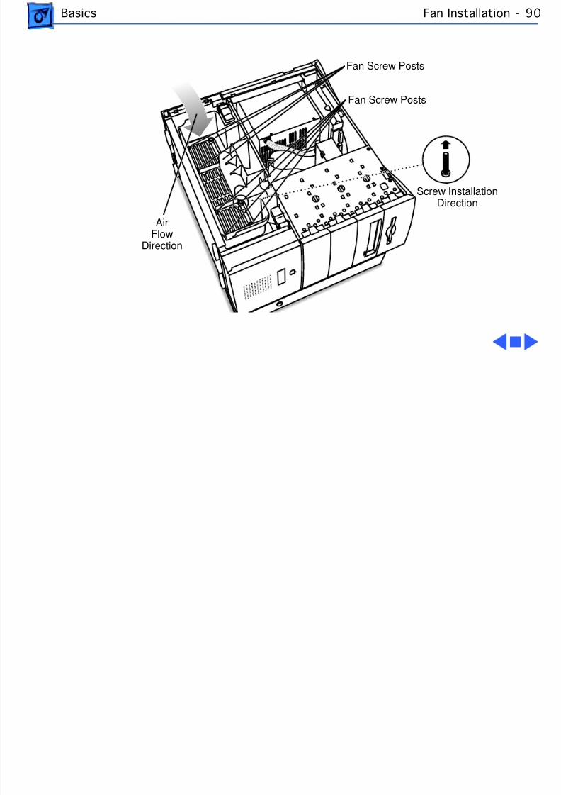
Basics Fan Installation - 8
Fan InstallationOne or two auxiliary fans may be installed in the bafflehandle. Third-party PCI card manufacturers may suggestthese fans be installed based on the thermal characteristics
of their cards.
Two sets of four fan screw posts indicate where you caninstall these fans. Fans must be positioned so they pull airinto the computer, not push air out. Be sure the screws don’textend down into the space where PCI cards or cables may bepresent.
8/19/2019 Powermac Server g3 Minitower
http://slidepdf.com/reader/full/powermac-server-g3-minitower 106/292
Basics Fan Installation - 9
AirFlow
Direction
Fan Screw Posts
Screw InstallationDirection
Fan Screw Posts
8/19/2019 Powermac Server g3 Minitower
http://slidepdf.com/reader/full/powermac-server-g3-minitower 107/292
Basics Repair Strategy - 9
Repair StrategyService the Power Mac/Server G3 computers throughmodule exchange and parts replacement. Customers canrequest on-site service from an Apple Authorized Service
Provider Plus (AASP+) Apple Assurance (US only), orApple Canada Technical Answerline (Cananda only). They canalso choose carry-in service from an AASP.
Ordering
Apple Service Providers planning to support the computersystems covered in this manual may purchase Service
modules and parts to develop servicing capability. To orderparts, use the AppleOrder (US only) or ARIS (Canada only)system and refer to the Power Macintosh G3 “Service PricePages.”
8/19/2019 Powermac Server g3 Minitower
http://slidepdf.com/reader/full/powermac-server-g3-minitower 108/292
Basics Repair Strategy - 9
Large businesses, universities, and K-12 accounts mustprovide a purchase order on all transactions, includingorders placed through the AppleOrder (US only) or ARIS(Canada only) system.
USA OrderingUS Service providers not enrolled in AppleOrder may faxtheir orders to Service Provider Support (512-908-8125) or mail them to
Apple Computer, Inc.Service Provider SupportMS 212-SPS
Austin, TX 78714-9125For US inquiries, please call Service Provider Support at800-919-2775 and select option #1.

8/19/2019 Powermac Server g3 Minitower
http://slidepdf.com/reader/full/powermac-server-g3-minitower 109/292
Basics Repair Strategy - 9
Canadian Ordering
Canadian Service providers not enrolled in ARIS may faxtheir orders to Service Provider Support in Canada(1-800-903-5284). For Canadian inquiries, please callService Provider Support at 905-513-5782 and selectoption #3.
8/19/2019 Powermac Server g3 Minitower
http://slidepdf.com/reader/full/powermac-server-g3-minitower 110/292
Basics Warranty/AppleCare/ARIS - 94
Warranty/AppleCare/ARIS
US Only
The Power Macintosh G3 computers are covered under theApple One-Year Limited Warranty. The AppleCare ServicePlan is also available for these products. Service Providersare reimbursed for warranty and AppleCare repairs made tothese computers. For pricing information, refer to “ServicePrice Pages.”
Canada Only
The Power Macintosh G3 computers are covered under
AppleCare. The Extended AppleCare Service Plan is alsoavailable for these products. Service Providers arereimbursed for warranty and AppleCare repairs made tothese computers. For pricing information, refer to “ServicePrice Pages.”
8/19/2019 Powermac Server g3 Minitower
http://slidepdf.com/reader/full/powermac-server-g3-minitower 111/292
http://www.apple.com
A little backgroundTwo decades ago, Apple m ade its nam e by bringing advanced technology to m ainstreamusers through extraordinarily easy-to-use products. In particular, we gained a reputationfor success in pioneering the educational use of com puters and cham pioning the advance-m ent of m ultim edia technology.
Although that reputation has rem ained rem arkably unchanged through the years—Apple is still regarded as the industry leader in both education and m ultim edia—thetechnology behind it has been altered practically beyond recognition, as have custom erexpectations. Today’s m ainstream com puter users want affordable high-perform ancesystem s that provide outstanding com m unications and m ultim edia capabilities. The PowerM acintosh G 3 series was developed to satisfy that need—and to exceed custom er expecta-tions about price/performance value.
The Power Macintosh G3 series product designW hen you talk about overall system design, you are really talking about a num ber ofthings—from the processor to the physical enclosure to the system software to the logicboard—whose interrelationships are central to the user experience. The Power Macintosh
G3 products were designed to m eet the needs of our custom ers for perform ance, flexibil-ity, and expandability through a stream lined developm ent process in which a single logicboard design provides a variety of capabilities. This approach sim plifies testing, speedingdevelopm ent and increasing system reliability. In addition, the use of greater num bers ofindustry-standard parts than in previous Apple system s makes Power Macintosh G3com puters even m ore affordable.
Logic board. A com puter’s logic board design is the ultim ate determinant of itsfunctionality, involving such key features as processor, m em ory setup (controller andexpansion capabilities), graphics support, and storage capabilities. The Power M acintosh G3series system s use a m ini-ATX board, which features, am ong other innovations, a faster systembus (66 m egahertz as opposed to 50 m egahertz, with room for further growth as processorspeeds continue to increase) to support higher performance. This relatively tiny board,roughly the size of this fact sheet, allows for outstanding expandability—for exam ple, byperm itting the hard disk drive to fit within the base of the desktop m odel, so that it can alsoeasily accom m odate a Zip drive. In addition, it features an easy-to-access audio/video card slotthat gives Apple the flexibility of offering a single product that provides a range of com m uni-cations and m ultim edia capabilities to m eet the varying needs of our users. For exam ple, thePower M acintosh G3 is currently available in two versions: one system with stereo-qualityaudio capabilities and the other a full-featured, m ultim edia-optim ized com puter that alsoprovides video-input/output capabilities and is suitable for content authoring.
Enclosure. The board’s efficient use of space is also the key to our ability to use thesam e logic board in two very different physical enclosures. The Power Macintosh G3 seriesis currently available in a sleek, low-lying desktop m odel and a convenient, space-savingm initower. Both enclosures reflect Apple’s tradition of user-centered design—offeringexceptionally easy access to the board for expansion and servicing.
System softwar e. These system s run Apple’s latest and already outstandinglysuccessful system software: M ac OS 8. Providing significant enhancem ents in the areas ofuser interface (including true m ultitasking and virtual m em ory capabilities) and Internetaccess and publishing (including integrated support for Java, and software tools that letusers easily publish inform ation on the Internet or a local intranet), M ac OS 8 has quicklygained a reputation for providing the industry’s best overall user experience.
The PowerM acintosh G3
Series: InnovativeProduct Design forAffordable High
Perform ance
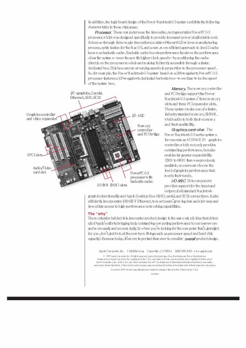
8/19/2019 Powermac Server g3 Minitower
http://slidepdf.com/reader/full/powermac-server-g3-minitower 112/292
In addition, the logic board design of the Power Macintosh G 3 system s exhibits the followingcharacteristics in these vital areas:
Processor. These com puters use the innovative, next-generation PowerPC G3processor, which was designed specifically to provide increased power at affordable cost.It does so through three m ajor innovations: a state-of-the-art 0.25-m icron m anufacturingprocess, optim ization for the M ac OS, and a new, m ore efficient approach to level 2 cacheknow n as backside cache. Backside cache boosts perform ance far above the perform ance
of earlier system s—even those with higher clock speeds—by positioning the cachedirectly on the processor m odule and m aking it directly accessible through a faster,dedicated bus. This bus can run at varying speeds in proportion to the processor speed.So, for exam ple, the Power M acintosh G 3 system based on a 266-m egahertz PowerPC G3processor features a 133-m egahertz dedicated backside bus—m ore than twice the speedof the system bus.
Memory. The m em ory controllerand PCI bridge support the PowerM acintosh G 3 system s’three m em oryslots and three PCI expansion slots.These system s m ake use of a faster,
industry-standard m em ory, SDRAM ,which adds to both their econom yand their availability.
Graphics contr oller. ThePow er Macintosh G3 series system sincorporate an ATI RAGE II+ graphicscontroller, which not only providesoutstanding performance, but alsoenables far greater expandability(2M B to 6M B) than was previouslyavailable, so users can choose thelevel of graphics performance thatm eets their needs.
I/O ASIC. This com ponentprovides support for the input andoutput of all standard M acintosh
graphics functionality and Apple Desktop Bus (ADB), serial, and SCSI connections. It alsoefficiently incorporates 10BASE-T Ethernet, to m eet users’growing dem ands for easy andim m ediate access to high-perform ance networking capabilities.
The “why”The m otivation behind this innovative product design is the sam e sim ple idea that drivesall of Apple’s efforts: bringing truly outstanding com puting performance to our users m oreand m ore easily and econom ically. So when you’re looking for the com puter that’s just rightfor you, don’t just look at the num bers (things such as processor speed and hard diskcapacity). Because today, it’s m ore im portant than ever to consider overall product design.
Apple Com puter, Inc. 1 Infinite Loop Cupertino, CA 95014 (408) 996-1010 www.apple.com© 1997 Apple Com puter, Inc. All rights reserved. Apple, the Apple logo, M ac, M acintosh, and Pow er Macintosh are
tradem arks of Apple Com puter, Inc., registered in the U.S.A. and other countries. Java is a tradem ark or registered tradem ark ofSun M icrosystem s, Inc. in the U.S.A. and other countries. Pow erPC is a tradem ark of International Business Machines Corporation,
used under license therefrom . Other product and com pany nam es mentioned herein m ay be tradem arks of their respective com panies.
Novem ber 1997. Product specifications are subject to change without notice. Printed in the U.S.A.
L02589A
3 DIM M (RAM ) slots
PowerPC G3processor withbackside cache
I/O: graphics, 2 serial,Ethernet, ADB, SCSI
Audio/Video
card slot
I/O ASIC
M em orycontrollerand PCI bridge
3 PCI slots
Graphics controllerand video expansion
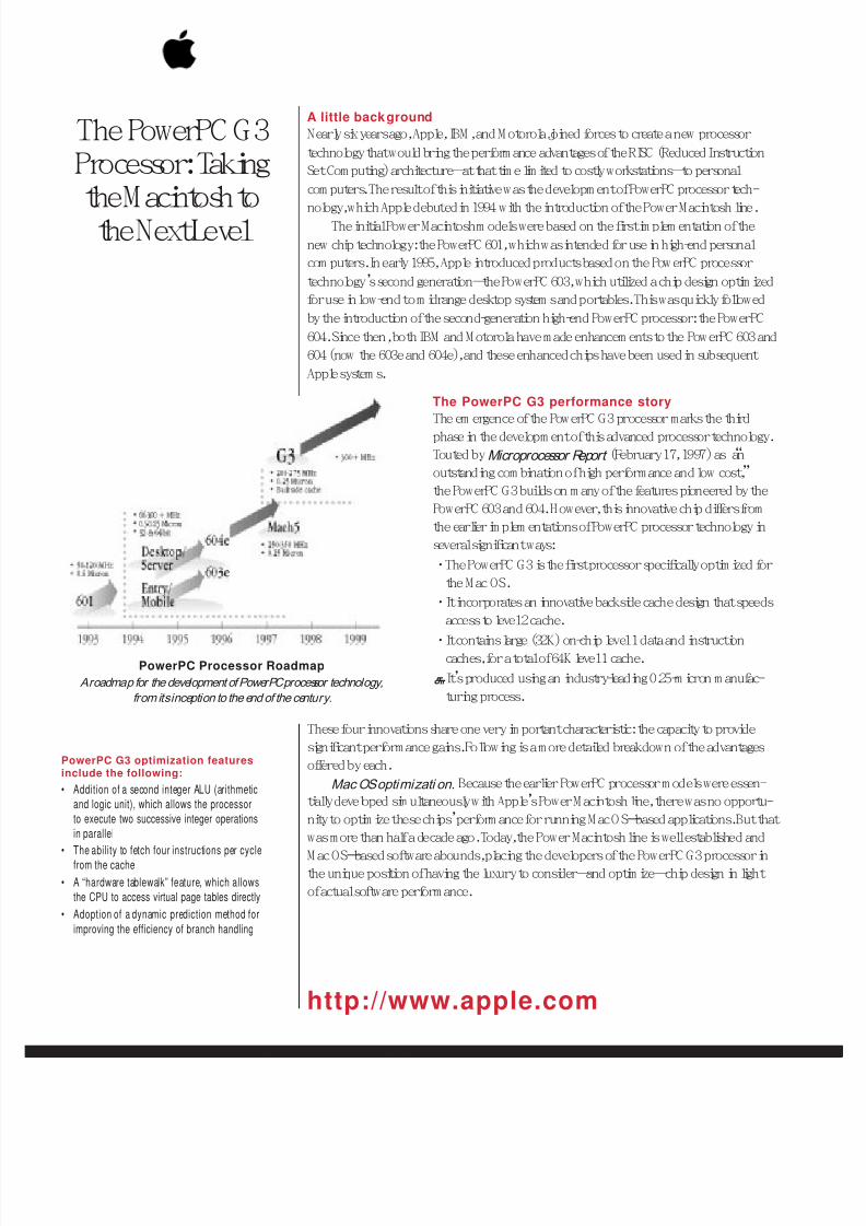
8/19/2019 Powermac Server g3 Minitower
http://slidepdf.com/reader/full/powermac-server-g3-minitower 113/292
http://www.apple.com
The PowerPC G3Processor: Taking
the M acintosh tothe Next Level
A little back groundNearly six years ago, Apple, IBM , and M otorola joined forces to create a new processortechnology that would bring the perform ance advantages of the RISC (Reduced InstructionSet Com puting) architecture—at that tim e lim ited to costly workstations—to personalcom puters. The result of this initiative was the developm ent of PowerPC processor tech-nology, which Apple debuted in 1994 with the introduction of the Power Macintosh line.
The initial Power Macintosh m odels were based on the first im plem entation of thenew chip technology: the PowerPC 601, which was intended for use in high-end personalcom puters. In early 1995, Apple introduced products based on the Pow erPC processortechnology’s second generation—the PowerPC 603, which utilized a chip design optim izedfor use in low-end to m idrange desktop system s and portables. This was quickly followedby the introduction of the second-generation high-end PowerPC processor: the PowerPC604. Since then, both IBM and M otorola have m ade enhancem ents to the PowerPC 603 and604 (now the 603e and 604e), and these enhanced chips have been used in subsequentApple system s.
The PowerPC G3 performance storyThe em ergence of the PowerPC G3 processor marks the thirdphase in the developm ent of this advanced processor technology.Touted by Microprocessor Report (February 17, 1997) as “anoutstanding com bination of high performance and low cost,”the PowerPC G3 builds on m any of the features pioneered by thePowerPC 603 and 604. However, this innovative chip differs fromthe earlier im plem entations of PowerPC processor technology inseveral significant ways:• The PowerPC G3 is the first processor specifically optim ized for
the M ac OS.• It incorporates an innovative backside cache design that speeds
access to level 2 cache.• It contains large (32K) on-chip level 1 data and instruction
caches, for a total of 64K level 1 cache.• It’s produced using an industry-leading 0.25-m icron m anufac-
turing process.
These four innovations share one very im portant characteristic: the capacity to providesignificant perform ance gains. Following is a m ore detailed breakdown of the advantagesoffered by each.
Mac OS optimizati on. Because the earlier PowerPC processor m odels were essen-tially developed sim ultaneously with Apple’s Power M acintosh line, there was no opportu-nity to optim ize these chips’perform ance for running M ac O S–based applications. But thatwas more than half a decade ago. Today, the Power Macintosh line is well established andM ac OS–based software abounds, placing the developers of the PowerPC G3 processor inthe unique position of having the luxury to consider—and optim ize—chip design in lightof actual software perform ance.
PowerPC G3 optimization featuresinclude the following:
• Addition of a second integer ALU (arithmeticand logic unit), which allows the processorto execute two successive integer operationsin parallel
• The ability to fetch four instructions per cyclefrom the cache
• A “hardware tablewalk” feature, which allowsthe CPU to access virtual page tables directly
• Adoption of a dynamic prediction method forimproving the efficiency of branch handling
PowerPC Processor RoadmapA roadmap for the development of PowerPC processor technology,
from its inception to the end of the century.
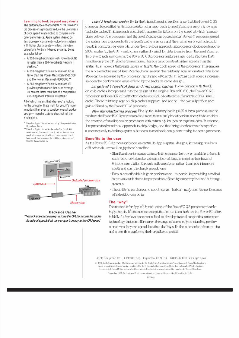
8/19/2019 Powermac Server g3 Minitower
http://slidepdf.com/reader/full/powermac-server-g3-minitower 114/292
Level 2 backside cache. By far the biggest boost to perform ance that the PowerPC G3offers can be credited to its incorporation of an approach to level 2 cache m em ory known asbackside cache. This approach effectively bypasses lim itations on the speed at which transac-tions between the processor and the level 2 cache can occur. Earlier PowerPC processors usedthe system bus to access both the level 2 cache m em ory and the m ain m em ory, which couldresult in conflicts. For exam ple, under the previous approach, at processor clock speeds above200 m egahertz, the CPU would often stall as it waited for data to arrive from the level 2 cache.
To prevent such slow downs, the PowerPC G3 processor features a new dedicated bus thathandles only the CPU/cache transactions. This bus can operate at higher speeds than thesystem bus—speeds that relate increm entally to the clock speed of the processor. This enablesthe m ore effective use of level 2 cache, because even the relatively large am ounts of data it canstore can be accessed by the processor rapidly and efficiently. In fact, as clock speeds increase,so does the perform ance value offered by the backside cache design.
Large level 1 (on-chip) data and i nstr uction caches. In com parison with the 8Kon-chip caches incorporated into the design of the original PowerPC 603, the PowerPC G3processor includes 32K of instruction cache and 32K of data cache, for a total of 64K level 1cache. These relatively large on-chip caches support—and add to—the overall perform ancegains offered by the PowerPC G3 processor.
New manufactur ing process. Finally, the industry-leading 0.25-m icron process used toproduce the PowerPC G3 processors does more than m erely boost perform ance; it also enablesthe creation of sm aller, cooler processors with extrem ely low power requirem ents. In essence,it represents a brand-new approach to chip design, one that brings workstation-class perfor-m ance not only to desktop system s, but even to notebook com puters—using the same processor.
Benefits to the userAs the PowerPC G3 processor becom es central to Apple system designs, increasing num bersof M acintosh users will enjoy these benefits:
•Significant perform ance gains, which enhance the power available to handlesuch resource-intensive tasks as video editing, Internet authoring, andW indows em ulation through software alone, rather than requiring m ore
costly and com plex hardw are add-ons•Even m ore affordable higher perform ance—in particular, providing a radical
im provem ent in the value proposition offered by our entry-level and m idrangesystem s
•The ability to purchase a notebook system that can truly offer the perform anceof a desktop com puter
The “why”The rationale for Apple’s introduction of the PowerPC G3 processor is strik-ingly sim ple. It’s the sam e concept that led us to em bark on the PowerPC effortinitially: At Apple, we are com m itted to developing and supporting processortechnology that can offer our entire range of users truly outstanding perfor-m ance—so they can spend less tim e dealing with the m echanics of com putingand m ore tim e exploring their creative potential.
Learning to look beyond megahertzThe performance enhancements o f the PowerPCG3 processor significantly reduce the usefulnessof clock speed in attempting to compare com-puter performance. Apple systems based onthis processor consistently outperform systemswith higher clock speeds— in fact, they alsooutperform Pentium II–based systems. Someexamples follow.• A 250-megahertz Macintosh PowerBook G3
is faster than a 266-m egahertz Pentium IIdesktop.*
• A 233-megahertz Power Macintosh G3 isfaster than the Power Macintosh 6500/300and the Power Macintosh 8600/300.**
• A 266-megahertz Power Macintosh G3provides performance that is on average30 percent faster than that of a comparable266-megahertz Pentium II system.*
All of which means that when you’re lookingfor the computer that’s right for you, i t’s moreimportant than ever to consider overall productdesign— megahertz alone does not tell thewhole story.
* Based on Apple internal tests running 15 separate AdobePhotoshop filters.
**Based on Apple internal testing using M acBench 4.0processor perform ance scores. Actual performance onapplications m ay vary. M acBench is a subsystem -levelbenchm ark that measures the relative perform ance ofM ac OS–based system s.
Apple Com puter, Inc. 1 Infinite Loop Cupertino, CA 95014 (408) 996-1010 www.apple.com© 1997 Apple Com puter, Inc. All rights reserved. Apple, the Apple logo, Mac, M acintosh, PowerBook, and Power Macintosh are
tradem arks of Apple Com puter, Inc., registered in the U .S.A. and other countries. Adobe is a tradem ark of Adobe System sIncorporated. PowerPC is a tradem ark of International Business M achines Corporation, used under license therefrom .
Novem ber 1997. Product specifications are subject to change w ithout notice. Printed in the U.S.A.
L02588A
Backside Cache
The backside cache design al lows the CPU to access the cachedirectly at speeds that vary proportional ly to the CPU speed
IIIIIIIIIIIIIIIIIIIIIIIIIIII
Dedicated processor bus
Memory bus
System bus
CPU Leve l 2 Ca c he
Pro ce sso r card
RAM
PCI s lo t s
8/19/2019 Powermac Server g3 Minitower
http://slidepdf.com/reader/full/powermac-server-g3-minitower 115/292
Service SourcK
SpecicationPower Macintosh/Server G3
Minitowe
8/19/2019 Powermac Server g3 Minitower
http://slidepdf.com/reader/full/powermac-server-g3-minitower 116/292
Specifications Introduction -
ntroductionecifications information for this product can be found in the Spec Database, which you cancess at Service Source Online (http://service.info.apple.com) or on Service Source CD.
pec Database at Service Source Online
om the Service Source Online home page, click Troubleshoot and Repair to access the mainpair procedures page. Then click either Apple Spec in the navigation table in the upperght corner of the page, or click Apple Spec Database from the list of reference tools below.
pec Database on Service Source CD
pen the CD and double-click the Apple Spec Database alias located at the top level of the CD.
8/19/2019 Powermac Server g3 Minitower
http://slidepdf.com/reader/full/powermac-server-g3-minitower 117/292
Service SourcK
Take AparPower Macintosh/Server G3
Minitowe
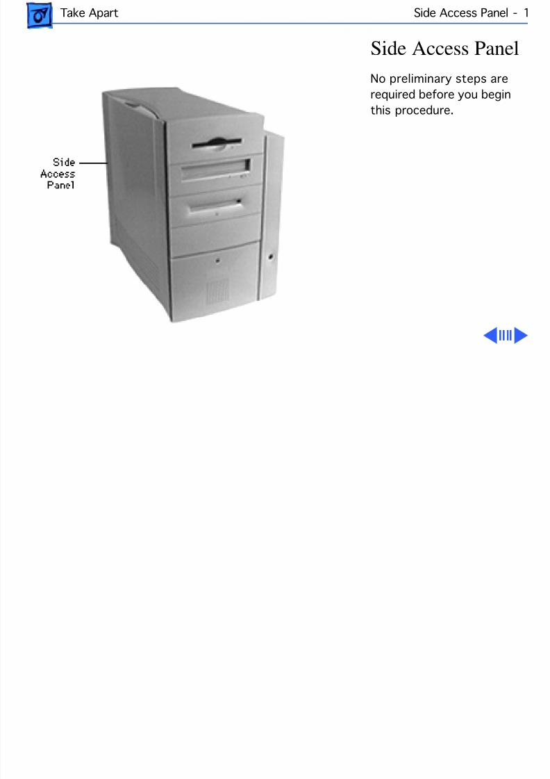
8/19/2019 Powermac Server g3 Minitower
http://slidepdf.com/reader/full/powermac-server-g3-minitower 118/292
Take Apart Side Access Panel - 1
Side Access PanelNo preliminary steps arerequired before you beginthis procedure.
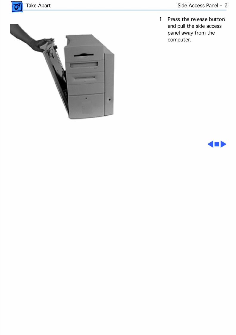
8/19/2019 Powermac Server g3 Minitower
http://slidepdf.com/reader/full/powermac-server-g3-minitower 119/292
Take Apart Side Access Panel - 2
1 Press the release buttonand pull the side accesspanel away from thecomputer.
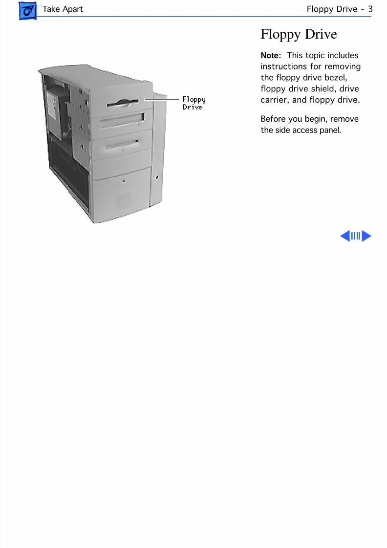
8/19/2019 Powermac Server g3 Minitower
http://slidepdf.com/reader/full/powermac-server-g3-minitower 120/292
Take Apart Floppy Drive -
Floppy DriveNote: This topic includesinstructions for removingthe floppy drive bezel,
floppy drive shield, drivecarrier, and floppy drive.
Before you begin, removethe side access panel.
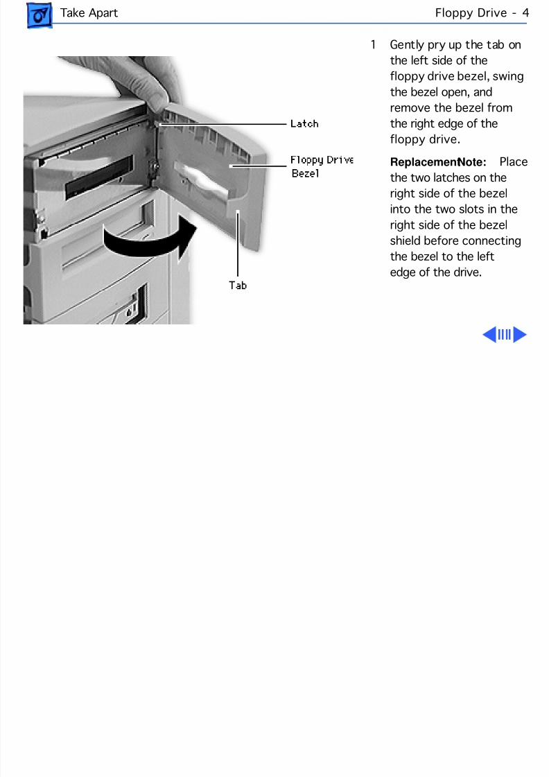
8/19/2019 Powermac Server g3 Minitower
http://slidepdf.com/reader/full/powermac-server-g3-minitower 121/292
Take Apart Floppy Drive -
1 Gently pry up the tab onthe left side of thefloppy drive bezel, swinthe bezel open, andremove the bezel from
the right edge of thefloppy drive.
Replacement Note: Pthe two latches on theright side of the bezelinto the two slots in theright side of the bezelshield before connecting
the bezel to the leftedge of the drive.
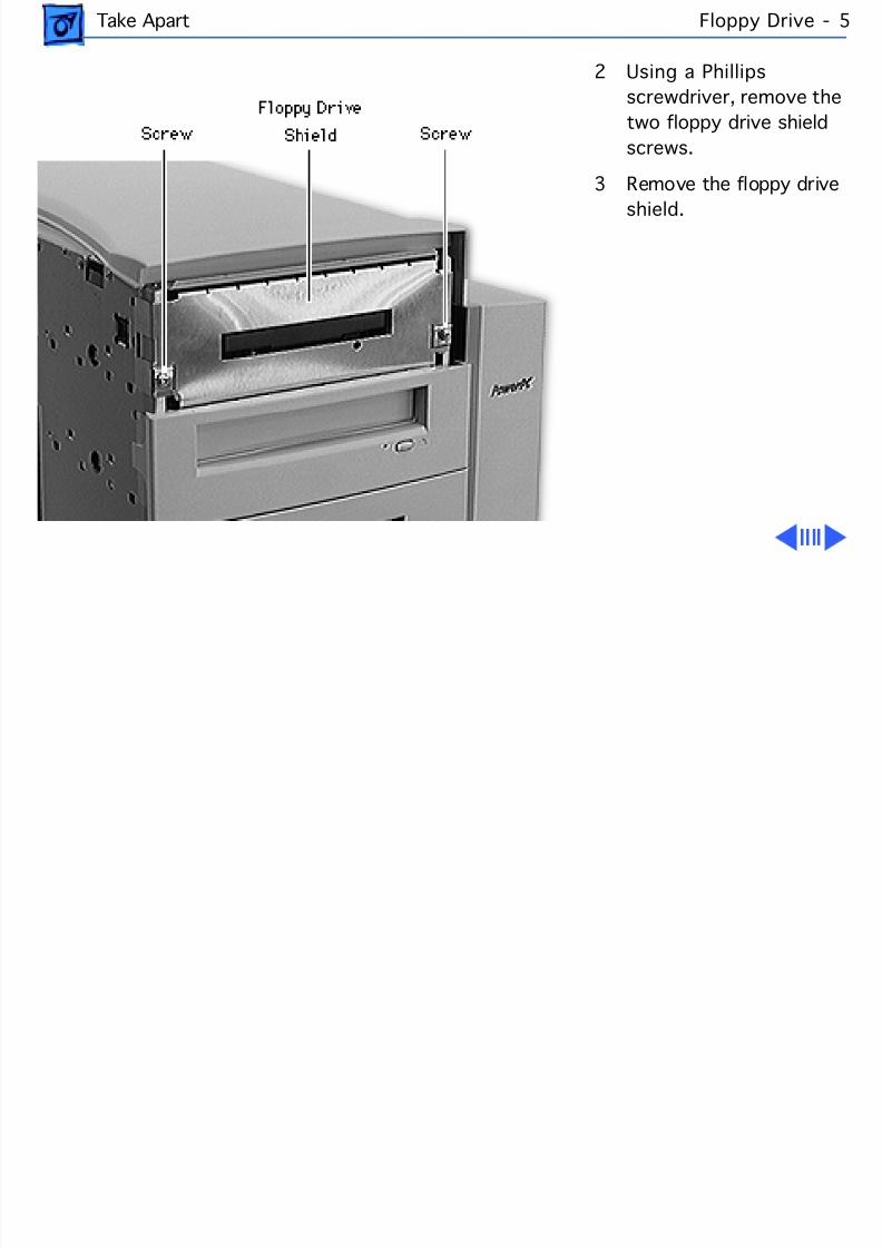
8/19/2019 Powermac Server g3 Minitower
http://slidepdf.com/reader/full/powermac-server-g3-minitower 122/292
Take Apart Floppy Drive -
2 Using a Phillipsscrewdriver, remove thetwo floppy drive shieldscrews.
3 Remove the floppy drive
shield.
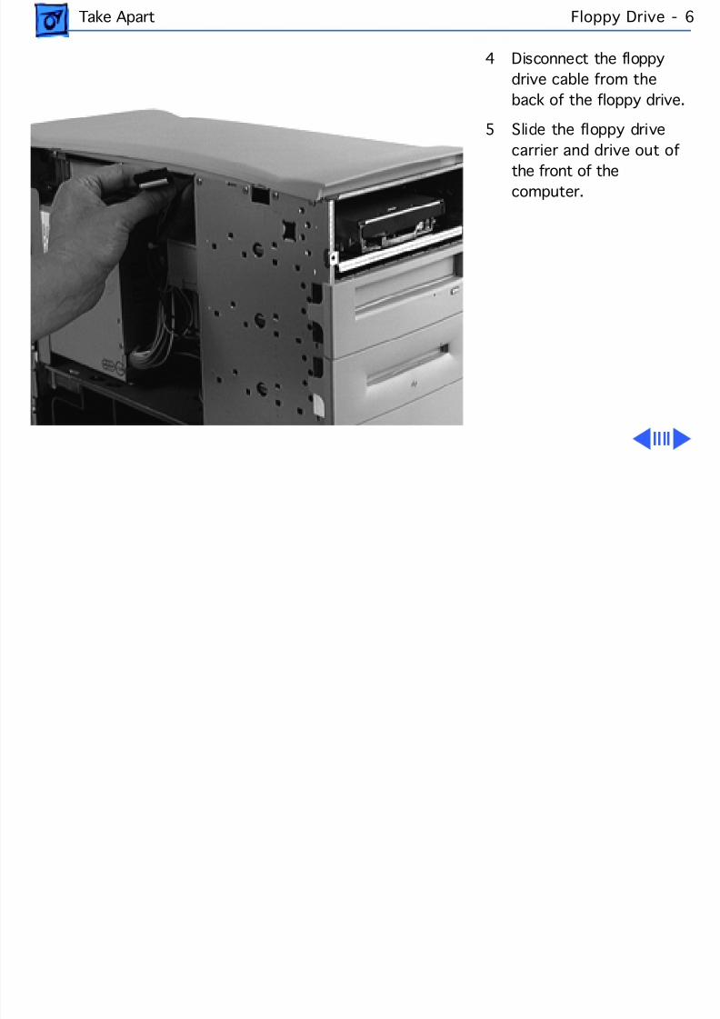
8/19/2019 Powermac Server g3 Minitower
http://slidepdf.com/reader/full/powermac-server-g3-minitower 123/292
Take Apart Floppy Drive -
4 Disconnect the floppydrive cable from theback of the floppy drive.
5 Slide the floppy drivecarrier and drive out of
the front of thecomputer.
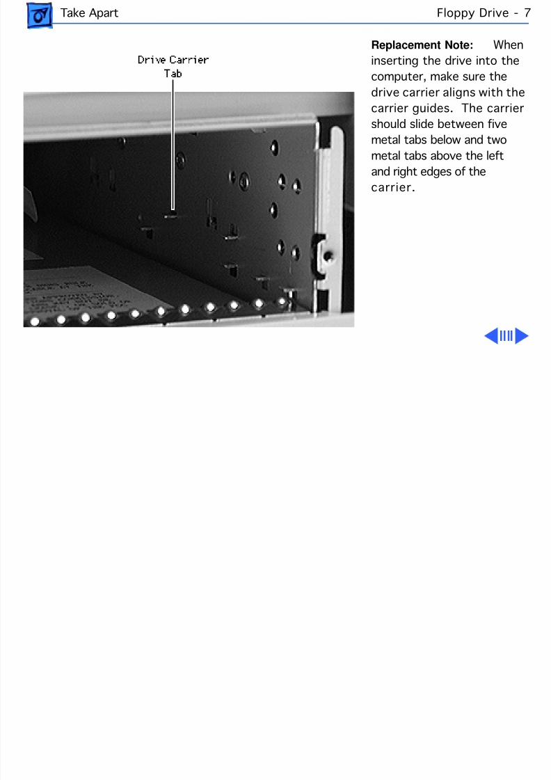
8/19/2019 Powermac Server g3 Minitower
http://slidepdf.com/reader/full/powermac-server-g3-minitower 124/292
Take Apart Floppy Drive -
Replacement Note: Winserting the drive into thecomputer, make sure thedrive carrier aligns with thecarrier guides. The carrier
should slide between fivemetal tabs below and twometal tabs above the leftand right edges of thecarrier.
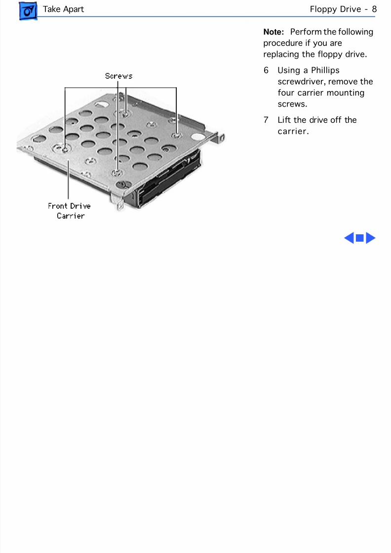
8/19/2019 Powermac Server g3 Minitower
http://slidepdf.com/reader/full/powermac-server-g3-minitower 125/292
Take Apart Floppy Drive -
Note: Perform the followinprocedure if you arereplacing the floppy drive.
6 Using a Phillipsscrewdriver, remove the
four carrier mountingscrews.
7 Lift the drive off thecarrier.
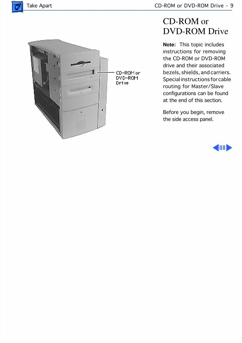
8/19/2019 Powermac Server g3 Minitower
http://slidepdf.com/reader/full/powermac-server-g3-minitower 126/292
Take Apart CD-ROM or DVD-ROM Drive
CD-ROM orDVD-ROM DriveNote: This topic includesinstructions for removingthe CD-ROM or DVD-ROMdrive and their associatedbezels, shields, and carriers.Special instructions for cablerouting for Master/Slaveconfigurations can be foundat the end of this section.
Before you begin, removethe side access panel.
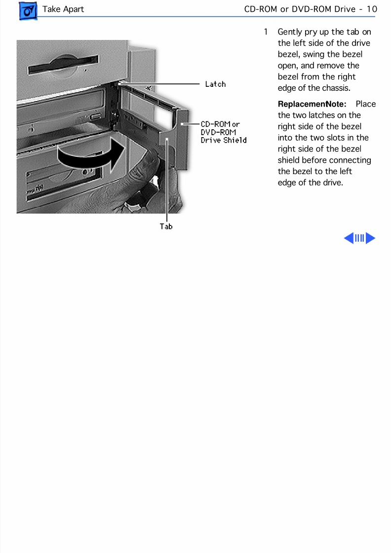
8/19/2019 Powermac Server g3 Minitower
http://slidepdf.com/reader/full/powermac-server-g3-minitower 127/292
Take Apart CD-ROM or DVD-ROM Drive -
1 Gently pry up the tab onthe left side of the drivebezel, swing the bezelopen, and remove thebezel from the right
edge of the chassis.Replacement Note: Pthe two latches on theright side of the bezelinto the two slots in theright side of the bezelshield before connectingthe bezel to the left
edge of the drive.
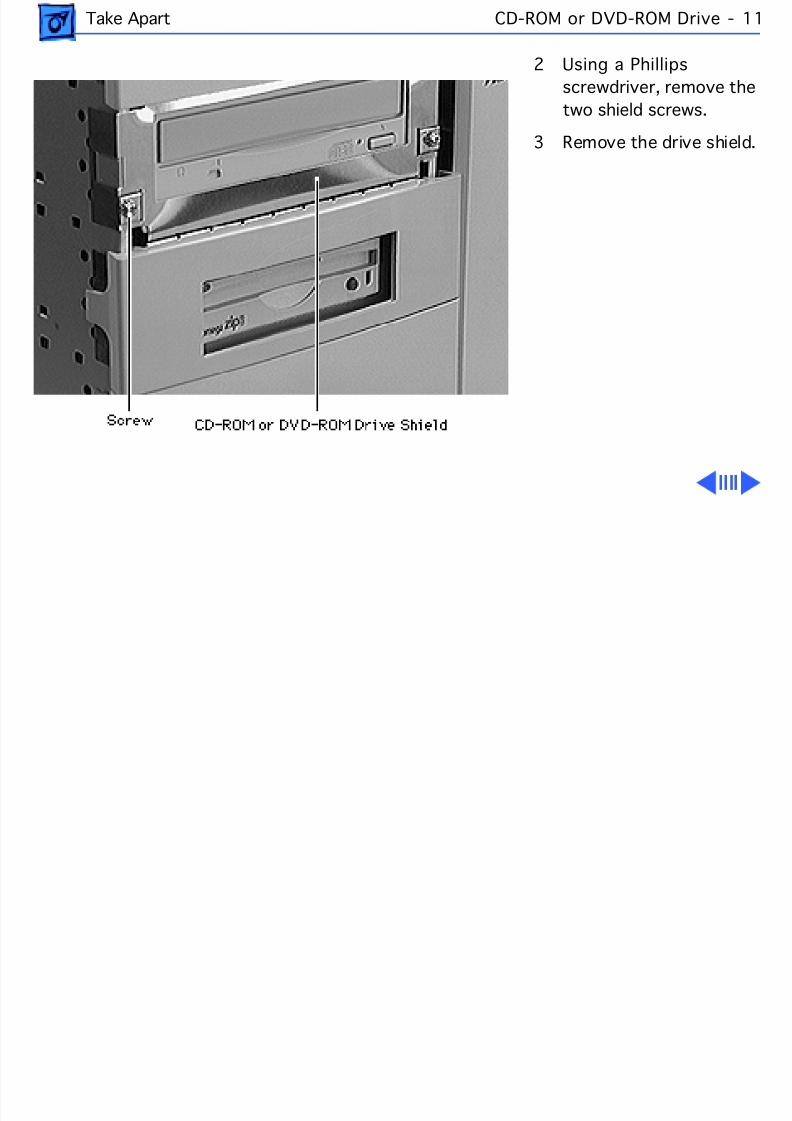
8/19/2019 Powermac Server g3 Minitower
http://slidepdf.com/reader/full/powermac-server-g3-minitower 128/292
Take Apart CD-ROM or DVD-ROM Drive -
2 Using a Phillipsscrewdriver, remove thetwo shield screws.
3 Remove the drive shield
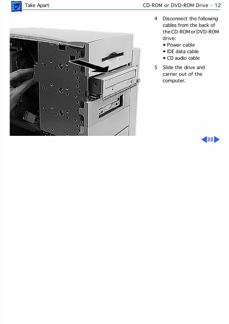
8/19/2019 Powermac Server g3 Minitower
http://slidepdf.com/reader/full/powermac-server-g3-minitower 129/292
Take Apart CD-ROM or DVD-ROM Drive -
4 Disconnect the followingcables from the back ofthe CD-ROM or DVD-Rdrive:• Power cable
• IDE data cable• CD audio cable
5 Slide the drive andcarrier out of thecomputer.

8/19/2019 Powermac Server g3 Minitower
http://slidepdf.com/reader/full/powermac-server-g3-minitower 130/292
Take Apart CD-ROM or DVD-ROM Drive -
Replacement Note: Winserting the drive into thecomputer, make sure thedrive carrier aligns with thecarrier guides. The carrier
should slide between fivemetal tabs below and twometal tabs above the leftand right edges of thecarrier.
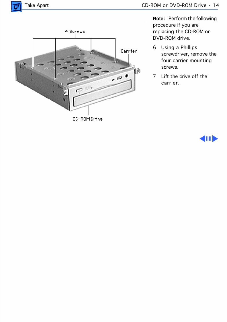
8/19/2019 Powermac Server g3 Minitower
http://slidepdf.com/reader/full/powermac-server-g3-minitower 131/292
Take Apart CD-ROM or DVD-ROM Drive -
Note: Perform the followinprocedure if you arereplacing the CD-ROM orDVD-ROM drive.
6 Using a Phillips
screwdriver, remove thefour carrier mountingscrews.
7 Lift the drive off thecarrier.
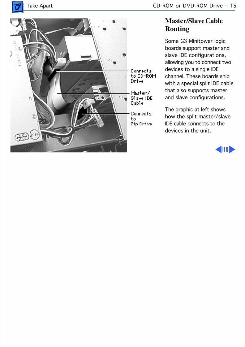
8/19/2019 Powermac Server g3 Minitower
http://slidepdf.com/reader/full/powermac-server-g3-minitower 132/292
Take Apart CD-ROM or DVD-ROM Drive -
Master/Slave CableRouting
Some G3 Minitower logicboards support master and
slave IDE configurations,allowing you to connect twodevices to a single IDEchannel. These boards shipwith a special split IDE cablthat also supports masterand slave configurations.
The graphic at left showshow the split master/slaveIDE cable connects to thedevices in the unit.
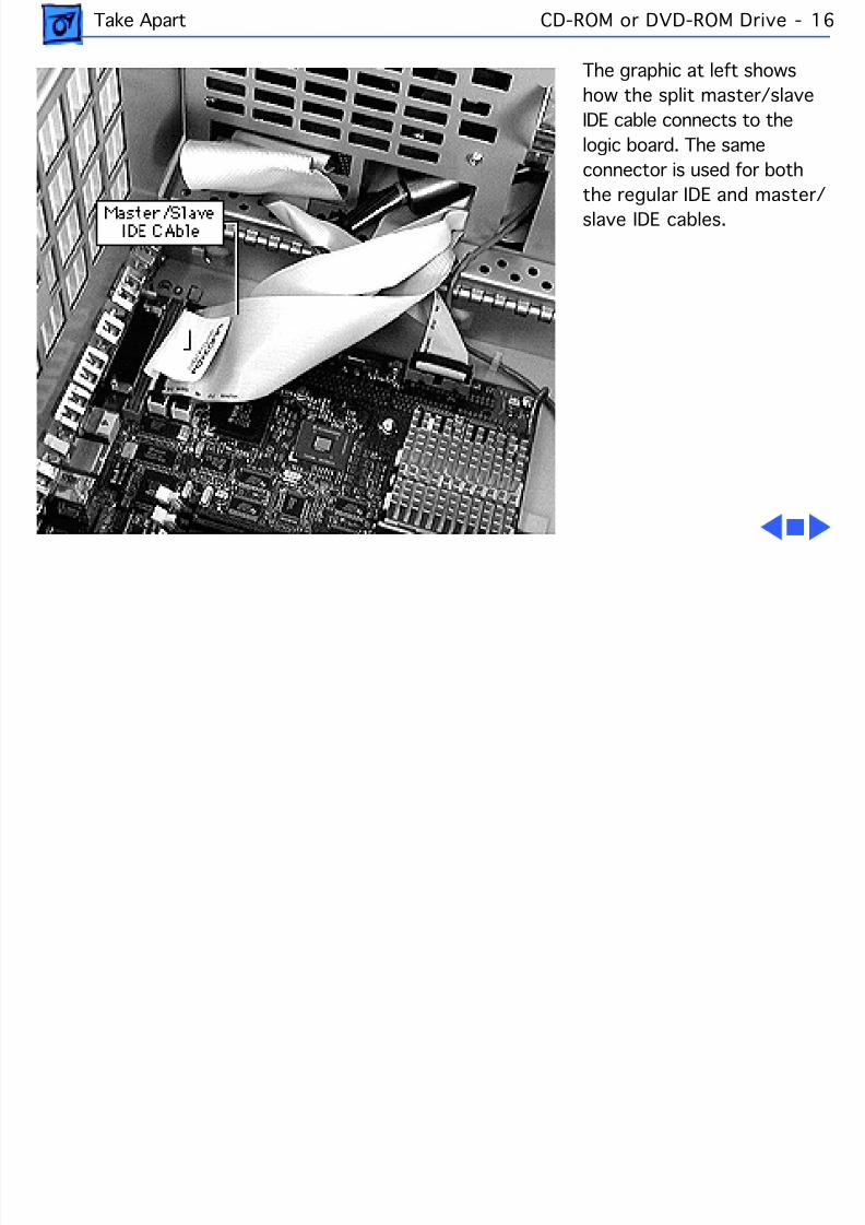
8/19/2019 Powermac Server g3 Minitower
http://slidepdf.com/reader/full/powermac-server-g3-minitower 133/292
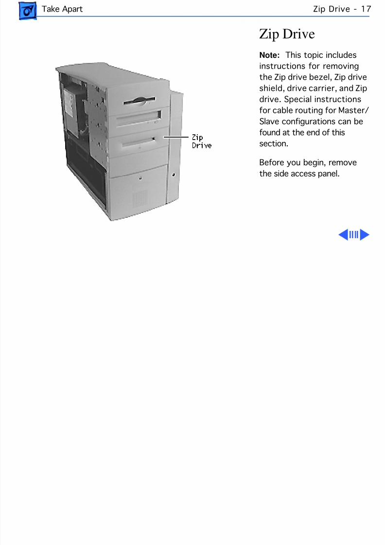
8/19/2019 Powermac Server g3 Minitower
http://slidepdf.com/reader/full/powermac-server-g3-minitower 134/292
Take Apart Zip Drive -
Zip DriveNote: This topic includesinstructions for removingthe Zip drive bezel, Zip drive
shield, drive carrier, and Zipdrive. Special instructionsfor cable routing for Master/Slave configurations can befound at the end of thissection.
Before you begin, removethe side access panel.
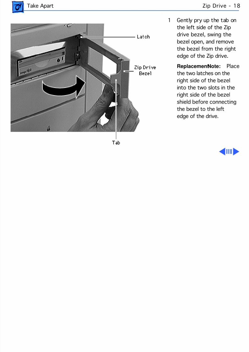
8/19/2019 Powermac Server g3 Minitower
http://slidepdf.com/reader/full/powermac-server-g3-minitower 135/292
Take Apart Zip Drive -
1 Gently pry up the tab onthe left side of the Zipdrive bezel, swing thebezel open, and removethe bezel from the right
edge of the Zip drive.Replacement Note: Pthe two latches on theright side of the bezelinto the two slots in theright side of the bezelshield before connectingthe bezel to the left
edge of the drive.
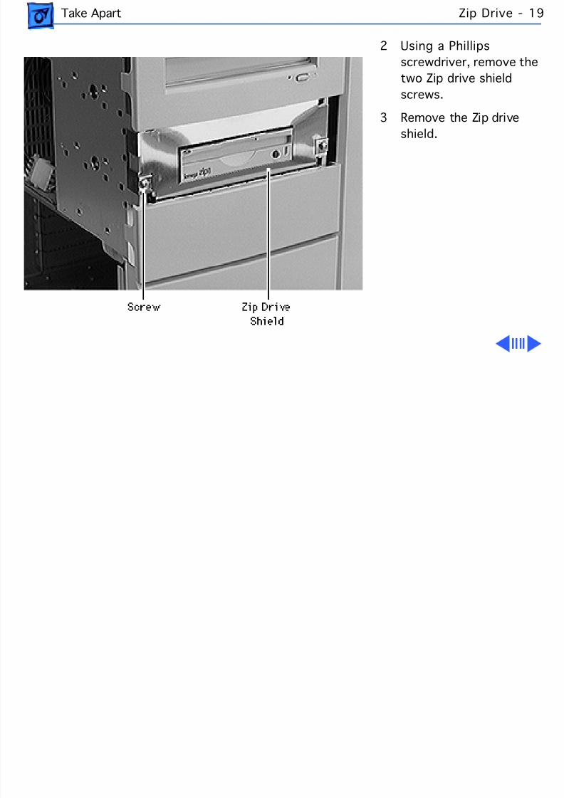
8/19/2019 Powermac Server g3 Minitower
http://slidepdf.com/reader/full/powermac-server-g3-minitower 136/292
Take Apart Zip Drive -
2 Using a Phillipsscrewdriver, remove thetwo Zip drive shieldscrews.
3 Remove the Zip drive
shield.
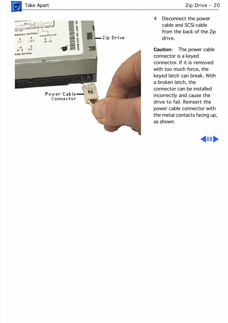
8/19/2019 Powermac Server g3 Minitower
http://slidepdf.com/reader/full/powermac-server-g3-minitower 137/292
Take Apart Zip Drive -
4 Disconnect the powercable and SCSI cablefrom the back of the Zipdrive.
Caution: The power cableconnector is a keyedconnector. If it is removedwith too much force, thekeyed latch can break. Witha broken latch, theconnector can be installedincorrectly and cause thedrive to fail. Reinsert thepower cable connector withthe metal contacts facing up,as shown.
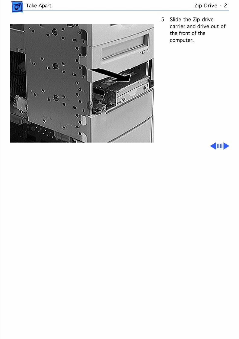
8/19/2019 Powermac Server g3 Minitower
http://slidepdf.com/reader/full/powermac-server-g3-minitower 138/292
Take Apart Zip Drive -
5 Slide the Zip drivecarrier and drive out ofthe front of thecomputer.

8/19/2019 Powermac Server g3 Minitower
http://slidepdf.com/reader/full/powermac-server-g3-minitower 139/292
Take Apart Zip Drive -
Replacement Note: Winserting the drive into thecomputer, make sure thedrive carrier aligns withthe carrier guides. The
carrier should slide betweenfive metal tabs below andtwo metal tabs above the leftand right edges of thecarrier.
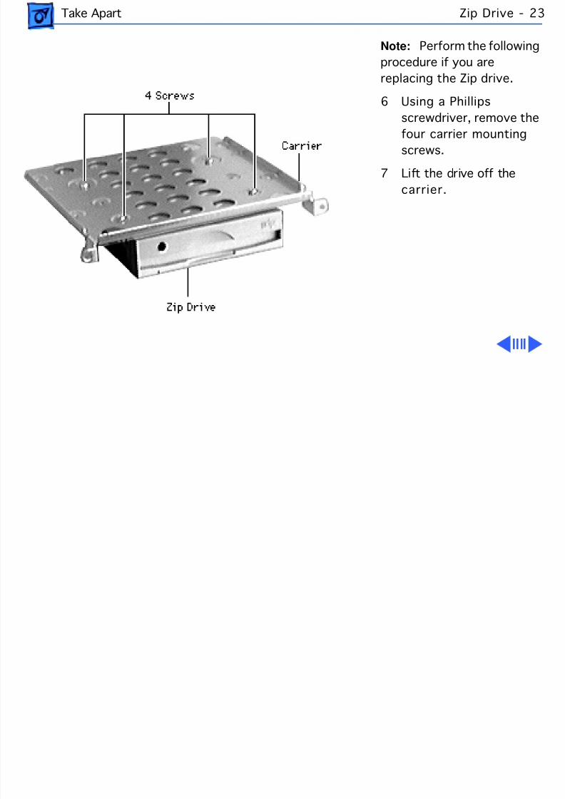
8/19/2019 Powermac Server g3 Minitower
http://slidepdf.com/reader/full/powermac-server-g3-minitower 140/292
Take Apart Zip Drive -
Note: Perform the followinprocedure if you arereplacing the Zip drive.
6 Using a Phillipsscrewdriver, remove the
four carrier mountingscrews.
7 Lift the drive off thecarrier.
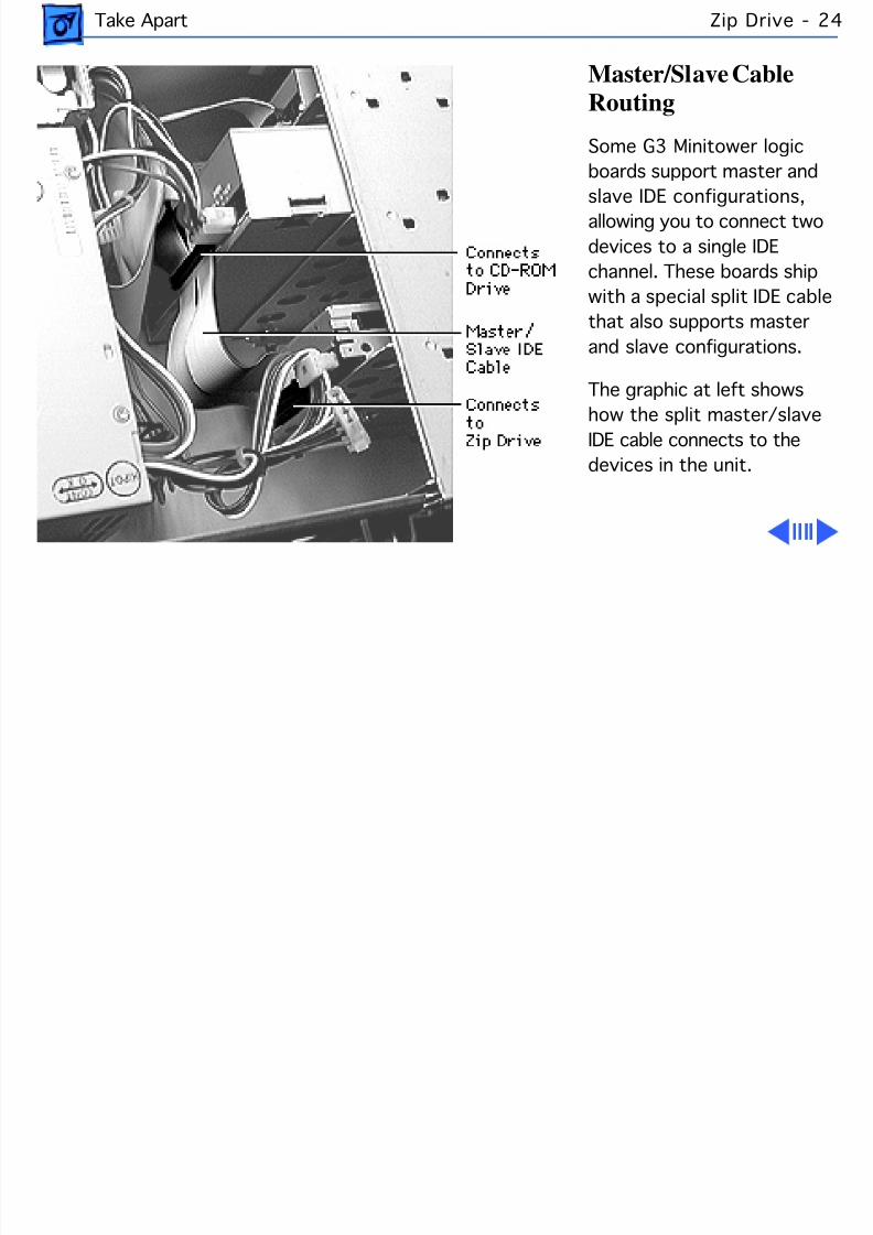
8/19/2019 Powermac Server g3 Minitower
http://slidepdf.com/reader/full/powermac-server-g3-minitower 141/292
Take Apart Zip Drive -
Master/Slave CableRouting
Some G3 Minitower logicboards support master and
slave IDE configurations,allowing you to connect twodevices to a single IDEchannel. These boards shipwith a special split IDE cablthat also supports masterand slave configurations.
The graphic at left showshow the split master/slaveIDE cable connects to thedevices in the unit.
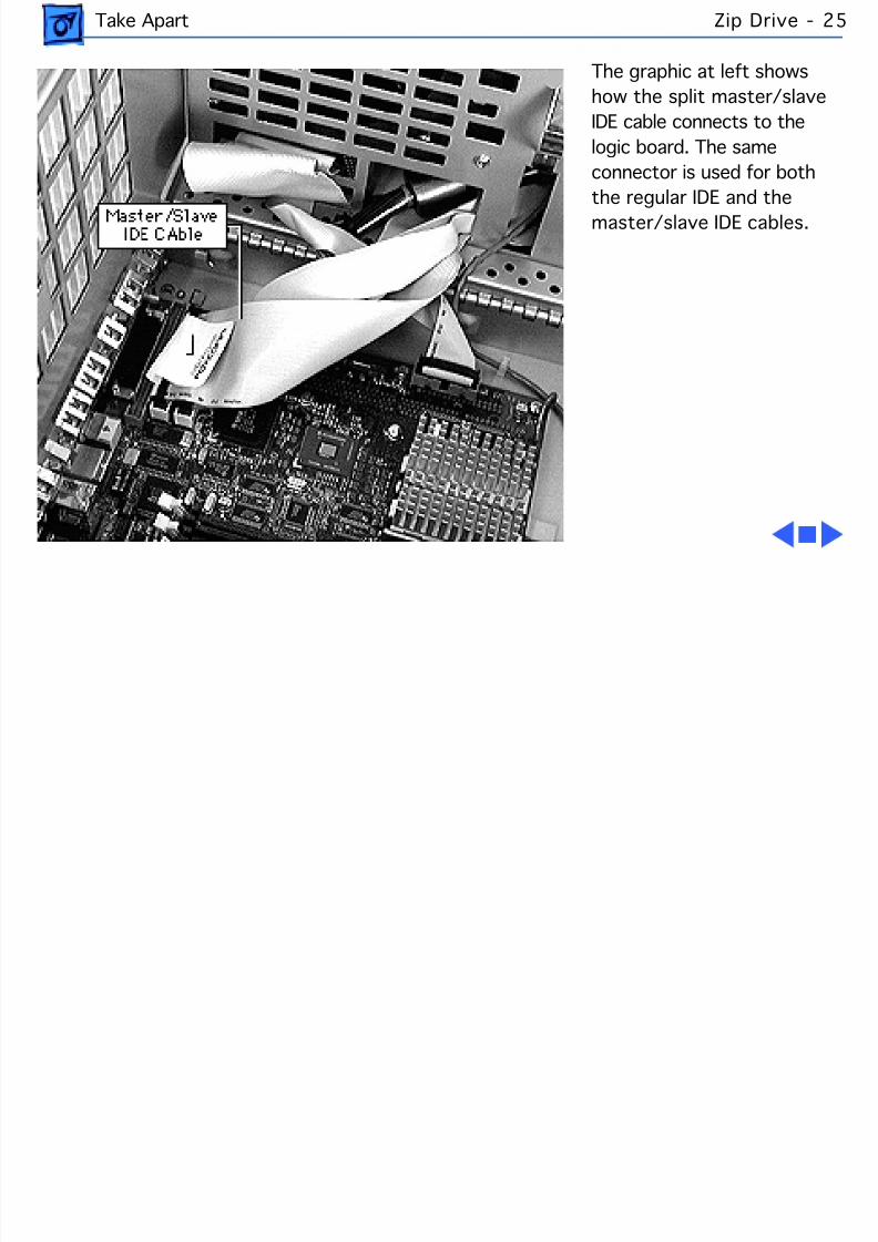
8/19/2019 Powermac Server g3 Minitower
http://slidepdf.com/reader/full/powermac-server-g3-minitower 142/292
Take Apart Zip Drive -
The graphic at left showshow the split master/slaveIDE cable connects to thelogic board. The sameconnector is used for both
the regular IDE and themaster/slave IDE cables.
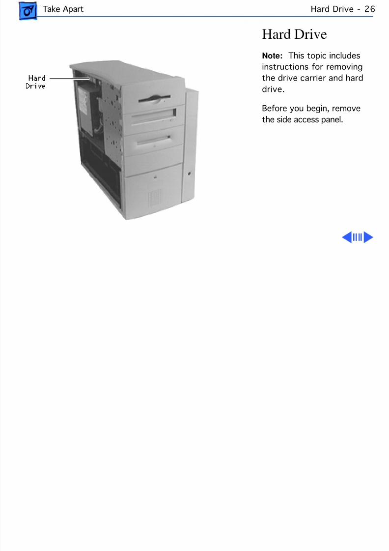
8/19/2019 Powermac Server g3 Minitower
http://slidepdf.com/reader/full/powermac-server-g3-minitower 143/292
Take Apart Hard Drive - 2
Hard DriveNote: This topic includesinstructions for removingthe drive carrier and hard
drive.
Before you begin, removethe side access panel.
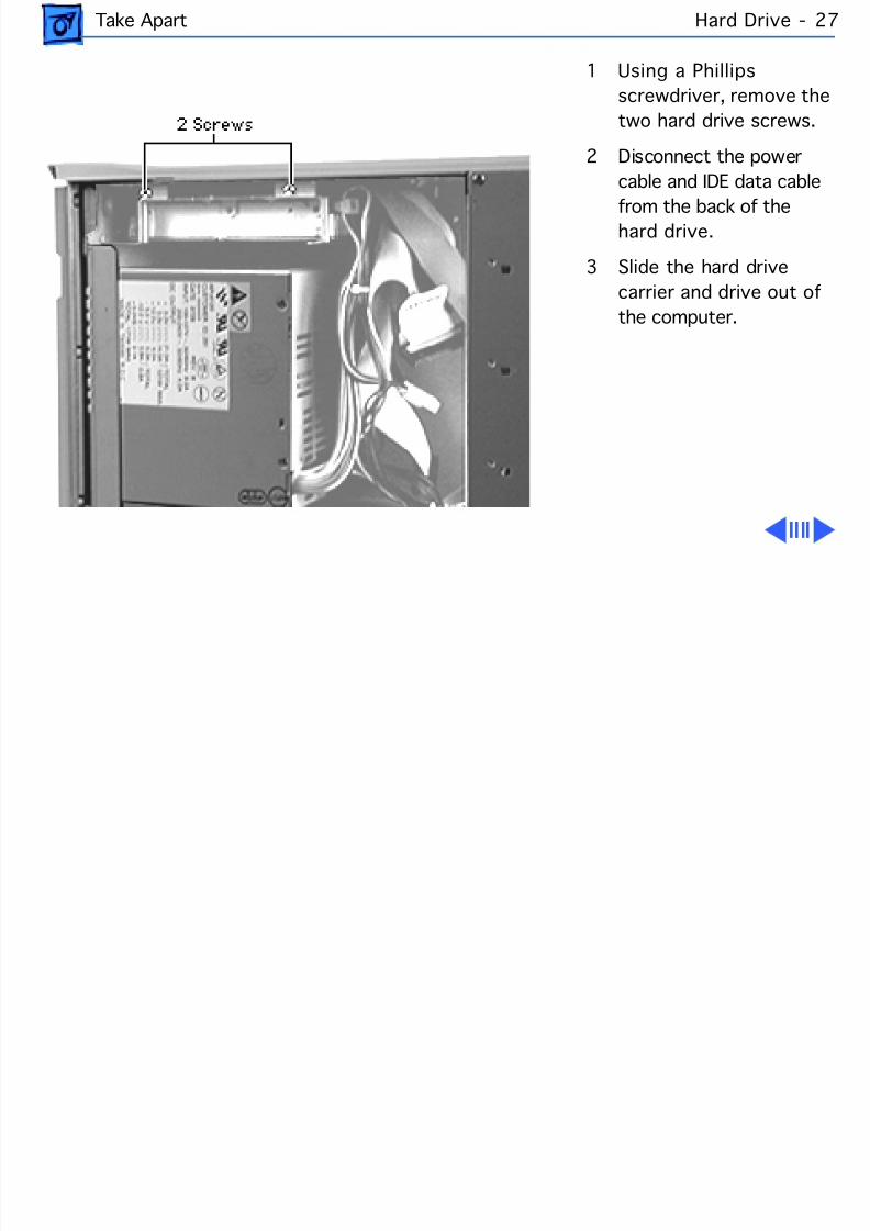
8/19/2019 Powermac Server g3 Minitower
http://slidepdf.com/reader/full/powermac-server-g3-minitower 144/292
Take Apart Hard Drive - 2
1 Using a Phillipsscrewdriver, remove thetwo hard drive screws.
2 Disconnect the powercable and IDE data cable
from the back of thehard drive.
3 Slide the hard drivecarrier and drive out ofthe computer.
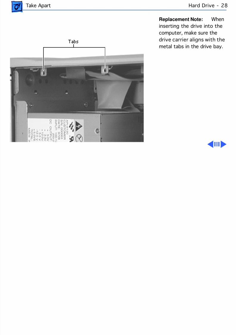
8/19/2019 Powermac Server g3 Minitower
http://slidepdf.com/reader/full/powermac-server-g3-minitower 145/292
Take Apart Hard Drive - 2
Replacement Note: Winserting the drive into thecomputer, make sure thedrive carrier aligns with themetal tabs in the drive bay.
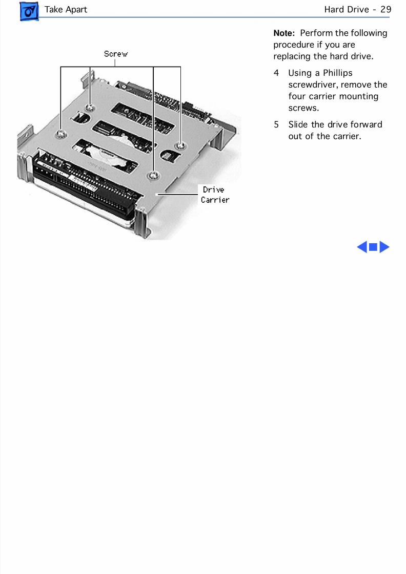
8/19/2019 Powermac Server g3 Minitower
http://slidepdf.com/reader/full/powermac-server-g3-minitower 146/292
Take Apart Hard Drive - 2
Note: Perform the followinprocedure if you arereplacing the hard drive.
4 Using a Phillipsscrewdriver, remove the
four carrier mountingscrews.
5 Slide the drive forwardout of the carrier.
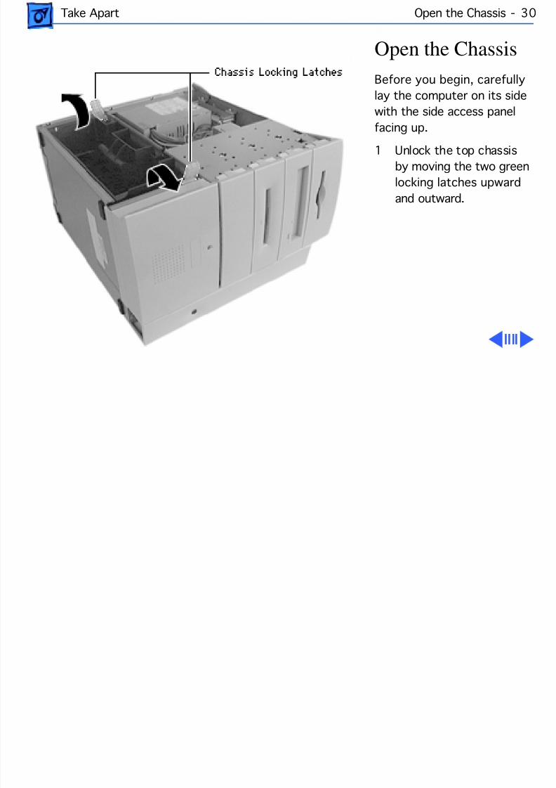
8/19/2019 Powermac Server g3 Minitower
http://slidepdf.com/reader/full/powermac-server-g3-minitower 147/292
Take Apart Open the Chassis - 30
Open the ChassisBefore you begin, carefullylay the computer on its sidewith the side access panel
facing up.1 Unlock the top chassis
by moving the two greenlocking latches upwardand outward.
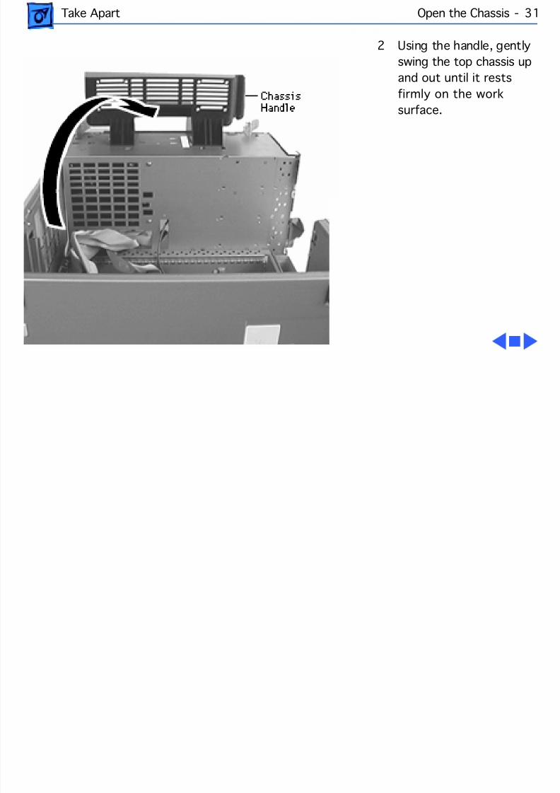
8/19/2019 Powermac Server g3 Minitower
http://slidepdf.com/reader/full/powermac-server-g3-minitower 148/292
Take Apart Open the Chassis - 31
2 Using the handle, gentlyswing the top chassis upand out until it restsfirmly on the worksurface.
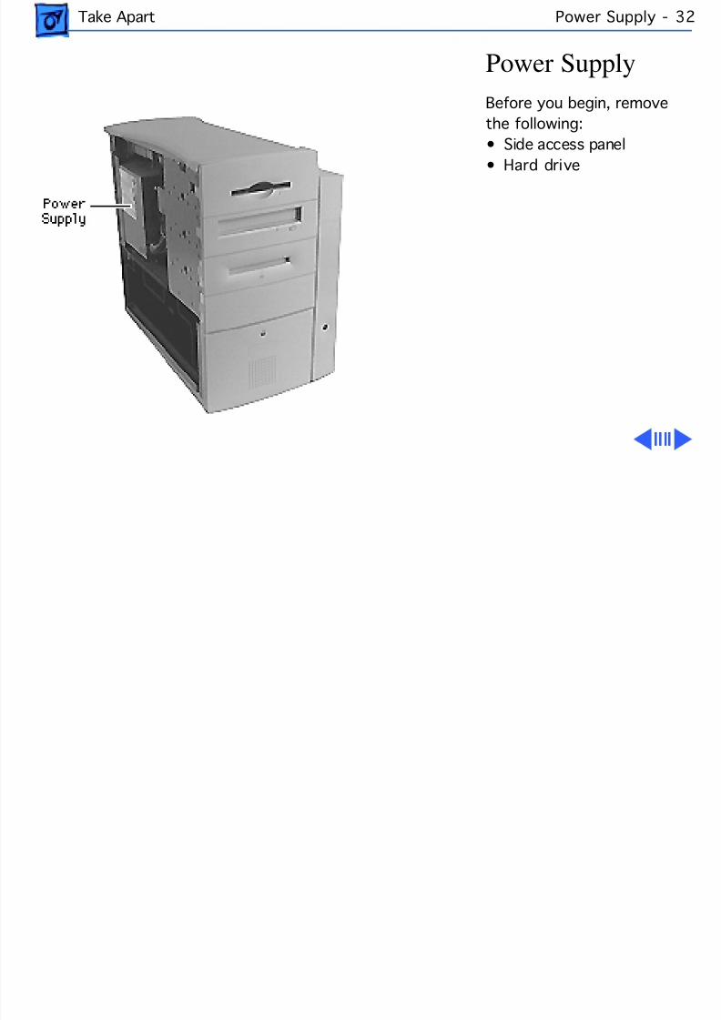
8/19/2019 Powermac Server g3 Minitower
http://slidepdf.com/reader/full/powermac-server-g3-minitower 149/292
Take Apart Power Supply - 3
Power SupplyBefore you begin, removethe following:• Side access panel
• Hard drive
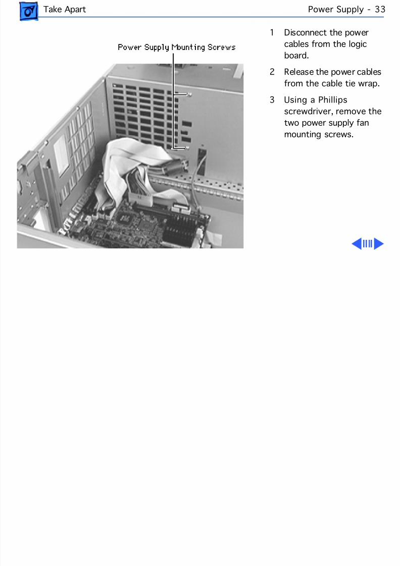
8/19/2019 Powermac Server g3 Minitower
http://slidepdf.com/reader/full/powermac-server-g3-minitower 150/292
Take Apart Power Supply - 3
1 Disconnect the powercables from the logicboard.
2 Release the power cablesfrom the cable tie wrap.
3 Using a Phillipsscrewdriver, remove thetwo power supply fanmounting screws.
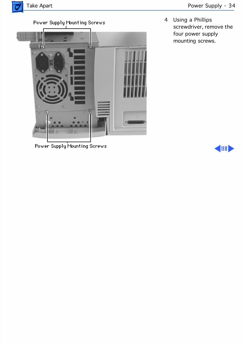
8/19/2019 Powermac Server g3 Minitower
http://slidepdf.com/reader/full/powermac-server-g3-minitower 151/292
Take Apart Power Supply - 3
4 Using a Phillipsscrewdriver, remove thefour power supplymounting screws.
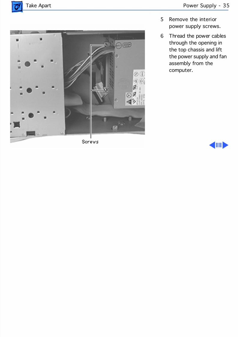
8/19/2019 Powermac Server g3 Minitower
http://slidepdf.com/reader/full/powermac-server-g3-minitower 152/292
Take Apart Power Supply - 3
5 Remove the interiorpower supply screws.
6 Thread the power cablesthrough the opening inthe top chassis and lift
the power supply and fanassembly from thecomputer.
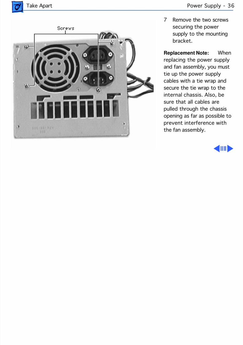
8/19/2019 Powermac Server g3 Minitower
http://slidepdf.com/reader/full/powermac-server-g3-minitower 153/292
Take Apart Power Supply - 3
7 Remove the two screwssecuring the powersupply to the mountingbracket.
Replacement Note: Wreplacing the power supplyand fan assembly, you musttie up the power supplycables with a tie wrap andsecure the tie wrap to theinternal chassis. Also, besure that all cables arepulled through the chassisopening as far as possible toprevent interference withthe fan assembly.
8/19/2019 Powermac Server g3 Minitower
http://slidepdf.com/reader/full/powermac-server-g3-minitower 154/292
Take Apart Power Supply - 3
IMPORTANT: You must set the power supply voltage switchto the correct setting (115V in the U.S.) to avoid damagingthe computer. See “Voltage Switch” in Basics forinstructions and an international voltage chart. The switchis accessible through the computer’s rear panel when the
power supply is installed.IMPORTANT: There is a power supply jumper on the logicboard located next to the PCI slots. If the logic board isinstalled in the PM G3 Minitower, the power supply jumpermust cover the pins marked “PS”. If the logic board isinstalled in the PM G3 Desktop model, the jumper mustcover the pins marked “Mac”. The logic board comes fromthe factory preset for the Desktop model (i.e. the powersupply jumper covers the pins marked “Mac”).
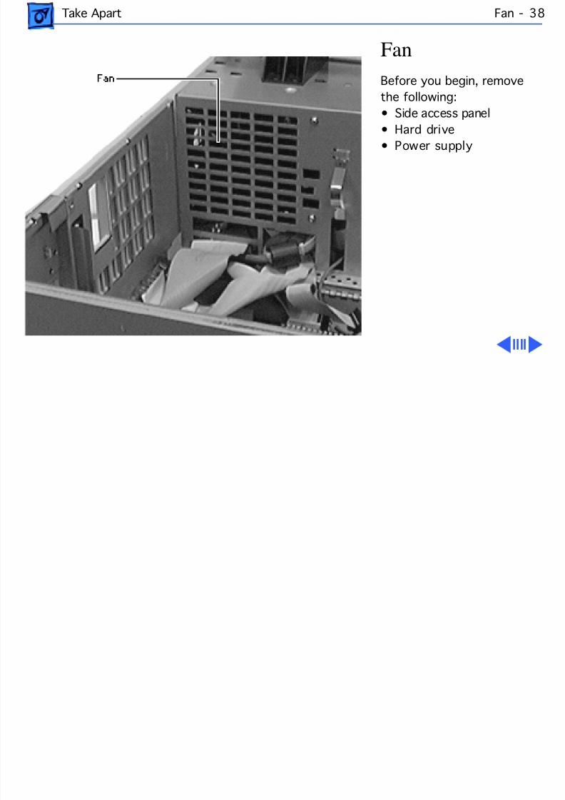
8/19/2019 Powermac Server g3 Minitower
http://slidepdf.com/reader/full/powermac-server-g3-minitower 155/292
Take Apart Fan -
FanBefore you begin, removethe following:• Side access panel
• Hard drive• Power supply
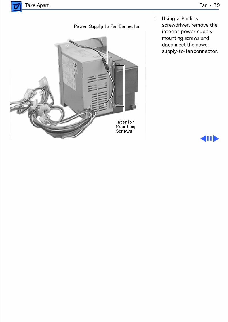
8/19/2019 Powermac Server g3 Minitower
http://slidepdf.com/reader/full/powermac-server-g3-minitower 156/292
Take Apart Fan -
1 Using a Phillipsscrewdriver, remove theinterior power supplymounting screws anddisconnect the power
supply-to-fan connector
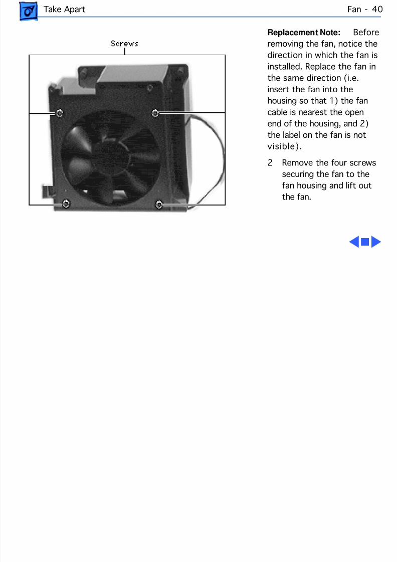
8/19/2019 Powermac Server g3 Minitower
http://slidepdf.com/reader/full/powermac-server-g3-minitower 157/292
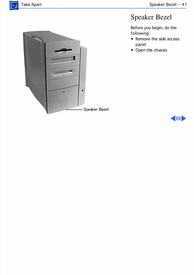
8/19/2019 Powermac Server g3 Minitower
http://slidepdf.com/reader/full/powermac-server-g3-minitower 158/292
Take Apart Speaker Bezel - 4
Speaker BezelBefore you begin, do thefollowing:• Remove the side access
panel• Open the chassis
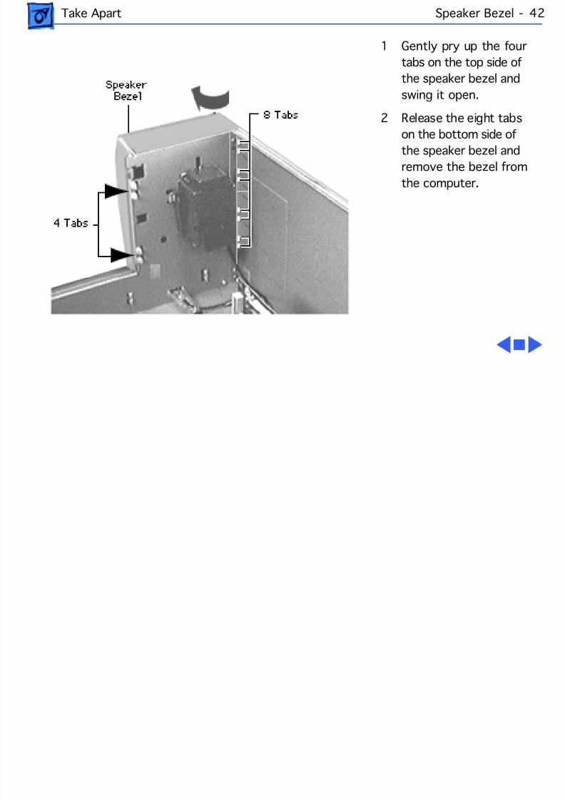
8/19/2019 Powermac Server g3 Minitower
http://slidepdf.com/reader/full/powermac-server-g3-minitower 159/292
Take Apart Speaker Bezel - 42
1 Gently pry up the fourtabs on the top side ofthe speaker bezel andswing it open.
2 Release the eight tabs
on the bottom side ofthe speaker bezel andremove the bezel fromthe computer.
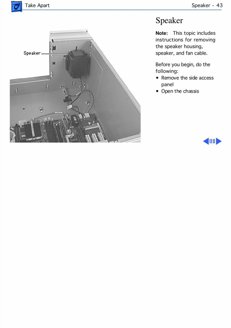
8/19/2019 Powermac Server g3 Minitower
http://slidepdf.com/reader/full/powermac-server-g3-minitower 160/292
Take Apart Speaker - 4
SpeakerNote: This topic includesinstructions for removingthe speaker housing,
speaker, and fan cable.
Before you begin, do thefollowing:• Remove the side access
panel• Open the chassis
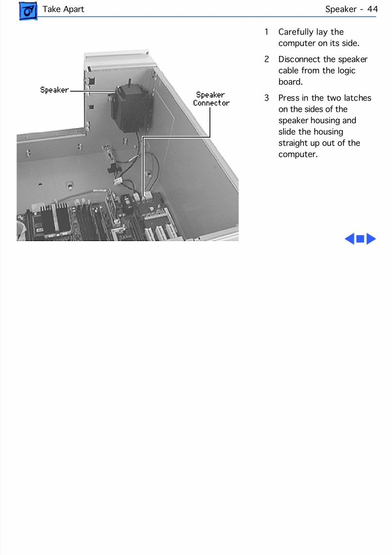
8/19/2019 Powermac Server g3 Minitower
http://slidepdf.com/reader/full/powermac-server-g3-minitower 161/292
Take Apart Speaker - 4
1 Carefully lay thecomputer on its side.
2 Disconnect the speakercable from the logicboard.
3 Press in the two latcheson the sides of thespeaker housing andslide the housingstraight up out of thecomputer.
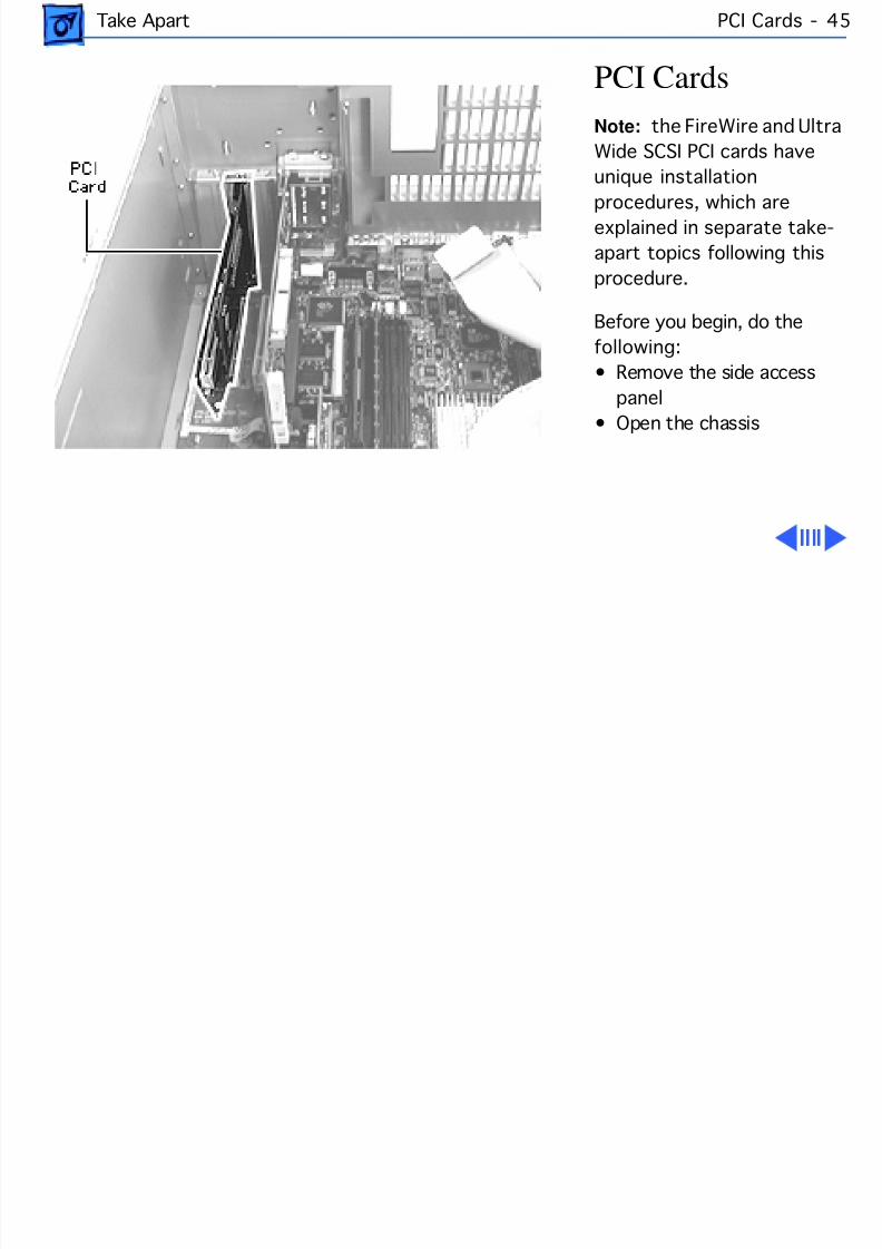
8/19/2019 Powermac Server g3 Minitower
http://slidepdf.com/reader/full/powermac-server-g3-minitower 162/292
Take Apart PCI Cards - 4
PCI CardsNote: the FireWire and UltrWide SCSI PCI cards haveunique installation
procedures, which areexplained in separate take-apart topics following thisprocedure.
Before you begin, do thefollowing:• Remove the side access
panel• Open the chassis
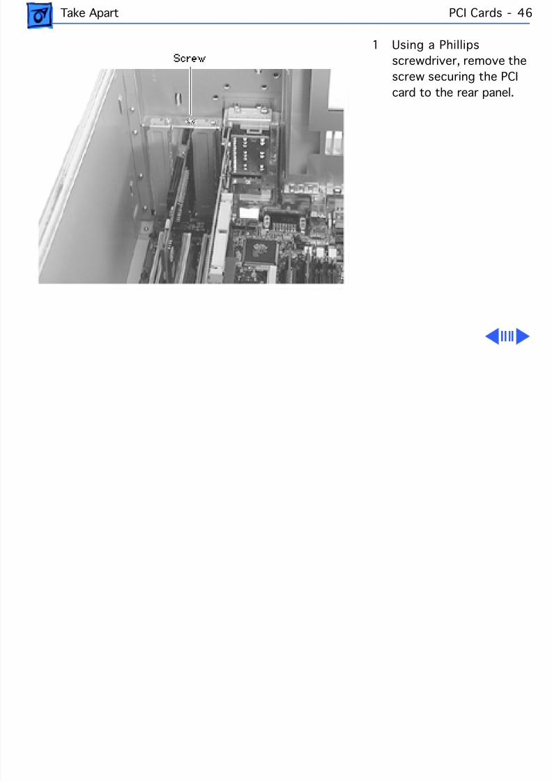
8/19/2019 Powermac Server g3 Minitower
http://slidepdf.com/reader/full/powermac-server-g3-minitower 163/292
Take Apart PCI Cards - 4
1 Using a Phillipsscrewdriver, remove thescrew securing the PCIcard to the rear panel.
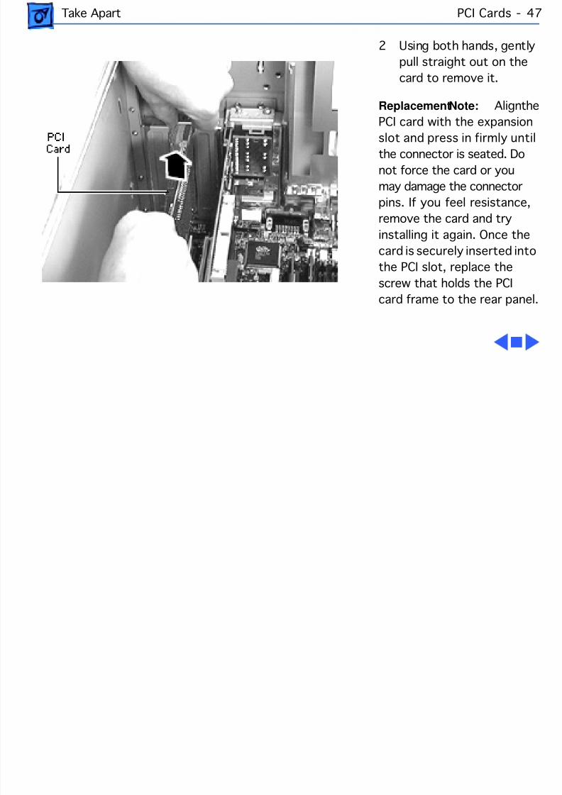
8/19/2019 Powermac Server g3 Minitower
http://slidepdf.com/reader/full/powermac-server-g3-minitower 164/292
Take Apart PCI Cards - 4
2 Using both hands, gentlypull straight out on thecard to remove it.
Replacement Note: AligPCI card with the expansionslot and press in firmly untilthe connector is seated. Donot force the card or youmay damage the connectorpins. If you feel resistance,remove the card and tryinstalling it again. Once thecard is securely inserted intothe PCI slot, replace thescrew that holds the PCIcard frame to the rear panel.
8/19/2019 Powermac Server g3 Minitower
http://slidepdf.com/reader/full/powermac-server-g3-minitower 165/292
Take Apart Ultra Wide SCSI PCI Card - 4
Ultra Wide SCSI PCI CardThe ultra wide SCSI card installs like any other PCI card (seethe PCI Cards take-apart topic for more information);however, the ultra wide SCSI card must be installed in the
first PCI slot (that is, the PCI slot nearest the video card). Inaddition, the ultra wide SCSI cable must be routed in a veryspecific manner. The procedure for installing and routing theultra wide SCSI cable is explained on the following pages.
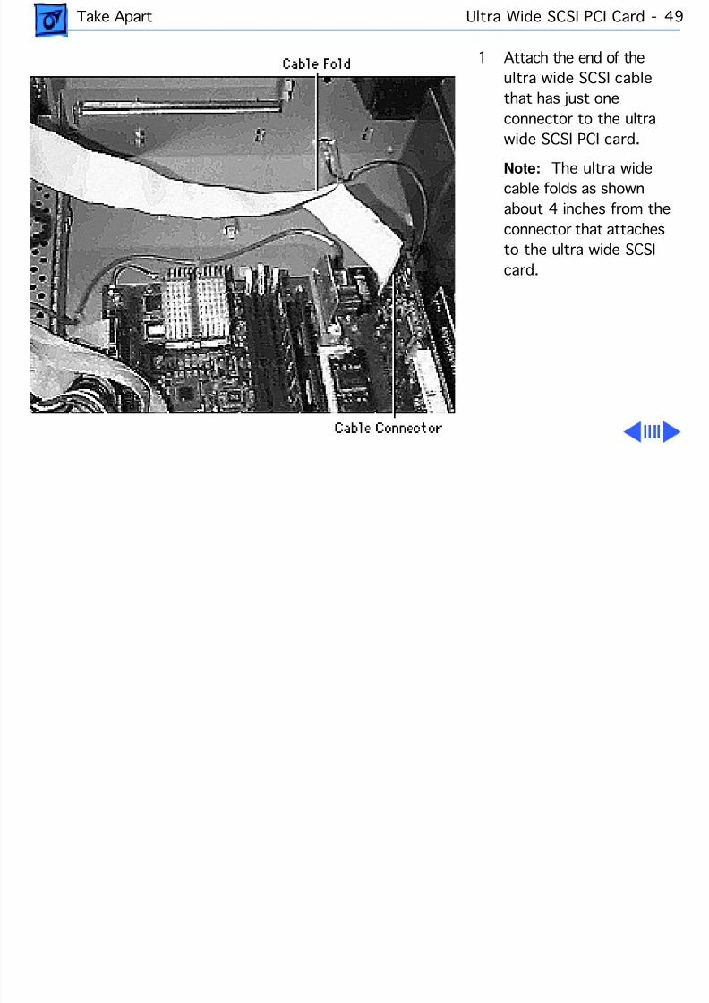
8/19/2019 Powermac Server g3 Minitower
http://slidepdf.com/reader/full/powermac-server-g3-minitower 166/292
Take Apart Ultra Wide SCSI PCI Card - 4
1 Attach the end of theultra wide SCSI cablethat has just oneconnector to the ultrawide SCSI PCI card.
Note: The ultra widecable folds as shownabout 4 inches from theconnector that attachesto the ultra wide SCSIcard.
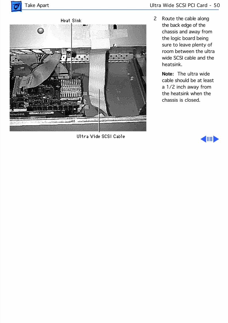
8/19/2019 Powermac Server g3 Minitower
http://slidepdf.com/reader/full/powermac-server-g3-minitower 167/292
Take Apart Ultra Wide SCSI PCI Card - 5
2 Route the cable alongthe back edge of thechassis and away fromthe logic board beingsure to leave plenty of
room between the ultrawide SCSI cable and theheatsink.
Note: The ultra widecable should be at leasta 1/2 inch away fromthe heatsink when thechassis is closed.
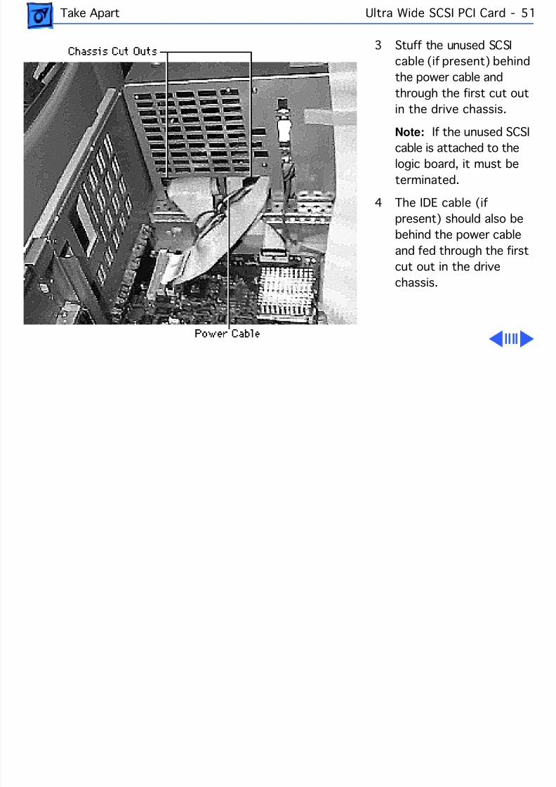
8/19/2019 Powermac Server g3 Minitower
http://slidepdf.com/reader/full/powermac-server-g3-minitower 168/292
Take Apart Ultra Wide SCSI PCI Card - 5
3 Stuff the unused SCSIcable (if present) behindthe power cable andthrough the first cut outin the drive chassis.
Note: If the unused SCcable is attached to thelogic board, it must beterminated.
4 The IDE cable (ifpresent) should also bebehind the power cableand fed through the firstcut out in the drivechassis.
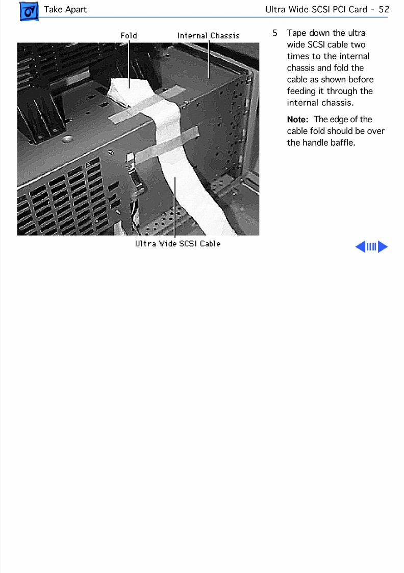
8/19/2019 Powermac Server g3 Minitower
http://slidepdf.com/reader/full/powermac-server-g3-minitower 169/292
Take Apart Ultra Wide SCSI PCI Card - 5
5 Tape down the ultrawide SCSI cable twotimes to the internalchassis and fold thecable as shown before
feeding it through theinternal chassis.
Note: The edge of thecable fold should be overthe handle baffle.
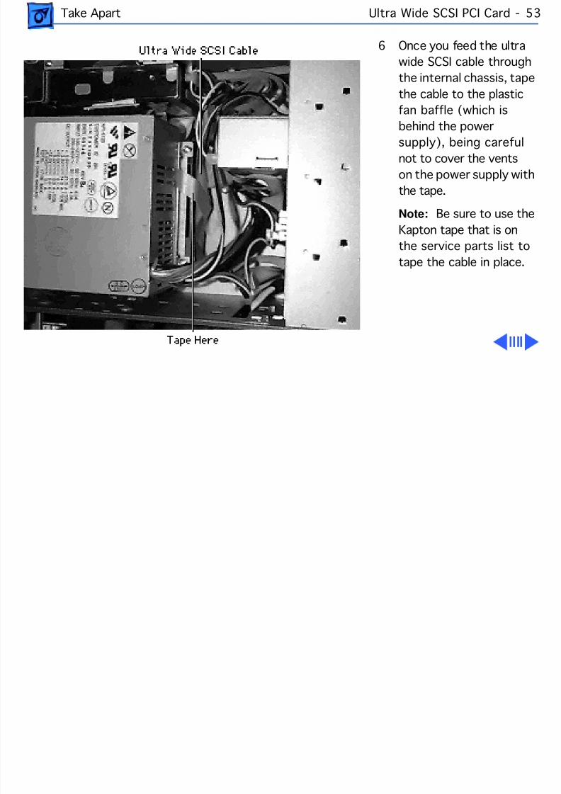
8/19/2019 Powermac Server g3 Minitower
http://slidepdf.com/reader/full/powermac-server-g3-minitower 170/292
Take Apart Ultra Wide SCSI PCI Card - 5
6 Once you feed the ultrawide SCSI cable throughthe internal chassis, tapethe cable to the plasticfan baffle (which is
behind the powersupply), being carefulnot to cover the ventson the power supply withthe tape.
Note: Be sure to use theKapton tape that is onthe service parts list to
tape the cable in place.
8/19/2019 Powermac Server g3 Minitower
http://slidepdf.com/reader/full/powermac-server-g3-minitower 171/292
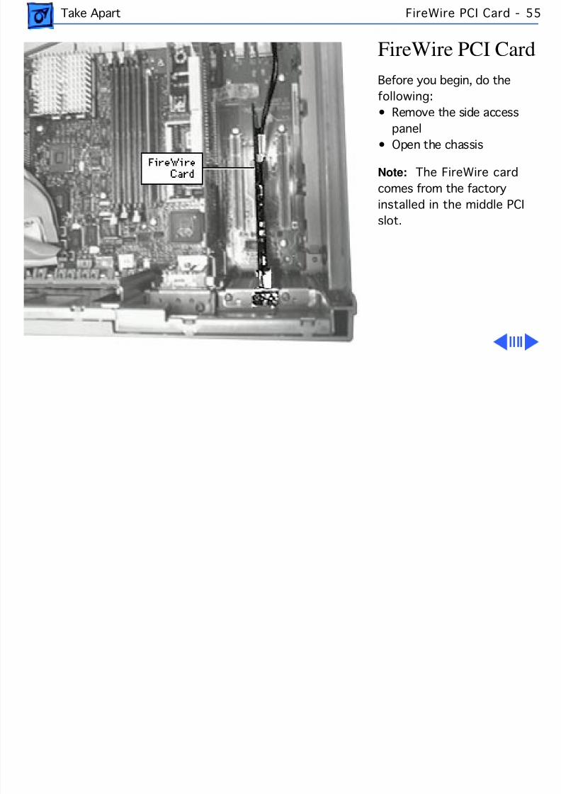
8/19/2019 Powermac Server g3 Minitower
http://slidepdf.com/reader/full/powermac-server-g3-minitower 172/292
Take Apart FireWire PCI Card - 5
FireWire PCI CardBefore you begin, do thefollowing:• Remove the side access
panel• Open the chassis
Note: The FireWire cardcomes from the factoryinstalled in the middle PCIslot.
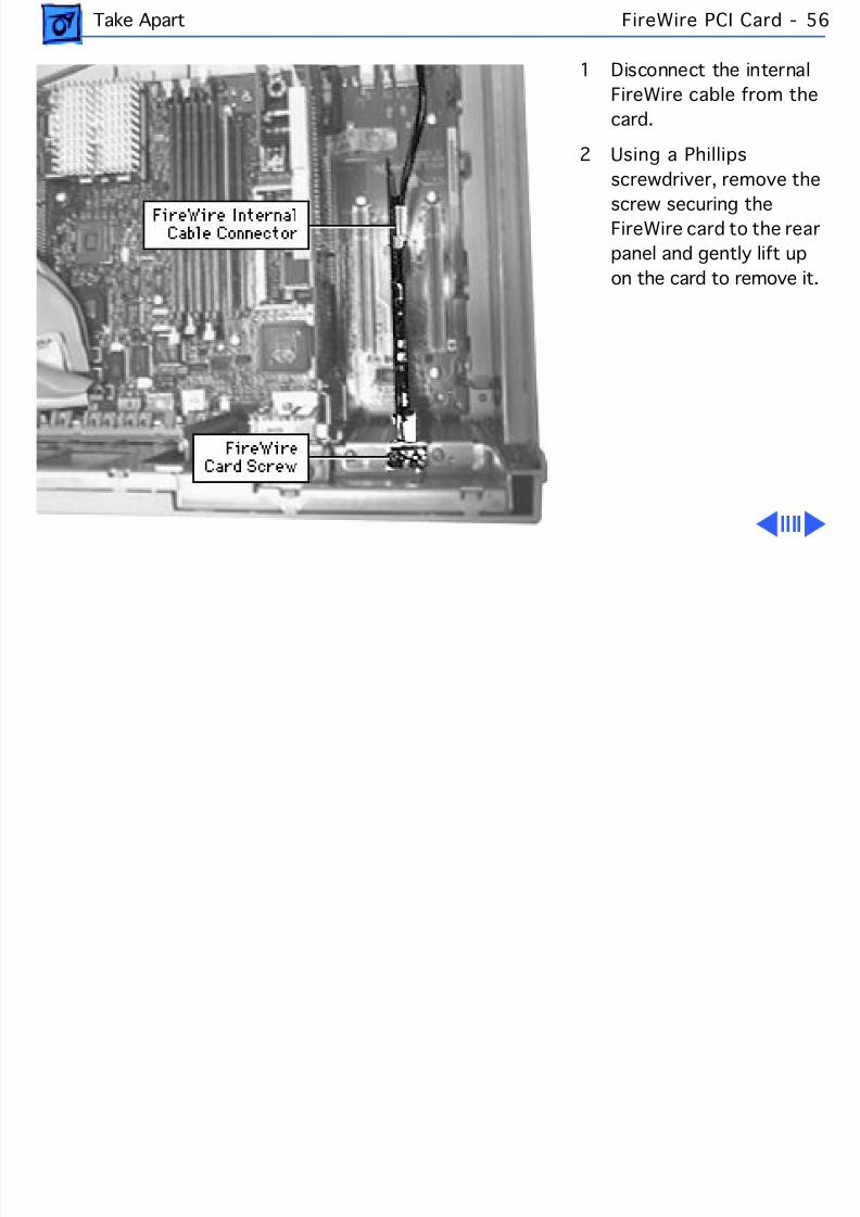
8/19/2019 Powermac Server g3 Minitower
http://slidepdf.com/reader/full/powermac-server-g3-minitower 173/292
Take Apart FireWire PCI Card - 5
1 Disconnect the internalFireWire cable from thcard.
2 Using a Phillipsscrewdriver, remove the
screw securing theFireWire card to the rearpanel and gently lift upon the card to remove it.
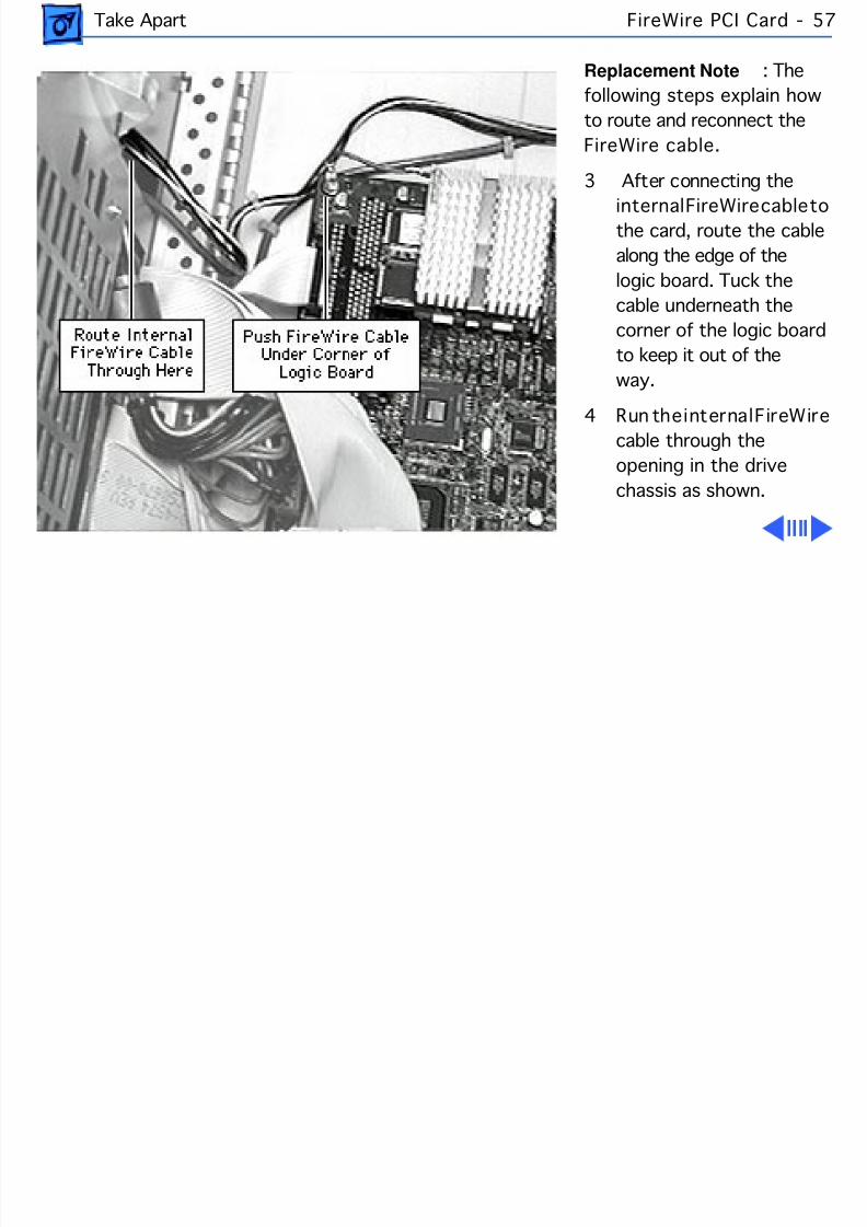
8/19/2019 Powermac Server g3 Minitower
http://slidepdf.com/reader/full/powermac-server-g3-minitower 174/292
Take Apart FireWire PCI Card - 5
Replacement Note : Thfollowing steps explain howto route and reconnect theFireWire cable.
3 After connecting the
internal FireWire cable tthe card, route the cablealong the edge of thelogic board. Tuck thecable underneath thecorner of the logic boardto keep it out of theway.
4 Run the internal FireWircable through theopening in the drivechassis as shown.
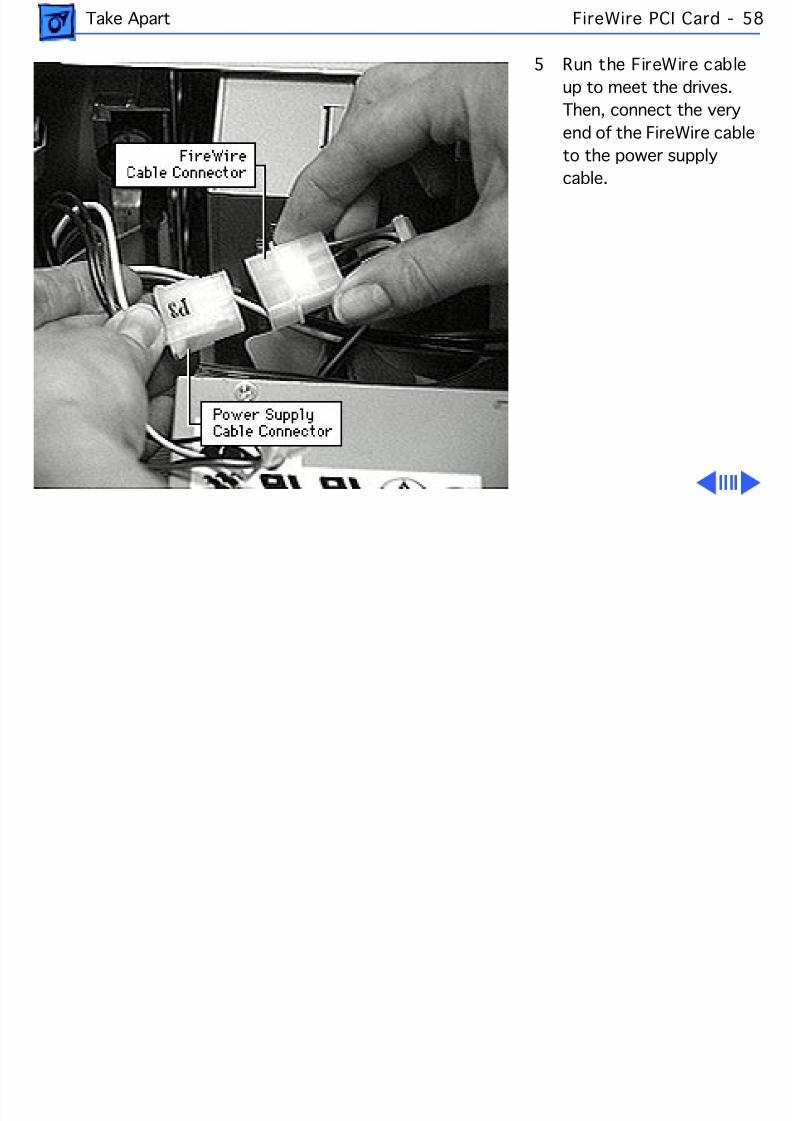
8/19/2019 Powermac Server g3 Minitower
http://slidepdf.com/reader/full/powermac-server-g3-minitower 175/292
Take Apart FireWire PCI Card - 5
5 Run the FireWire cableup to meet the drives.Then, connect the veryend of the FireWire cableto the power supply
cable.
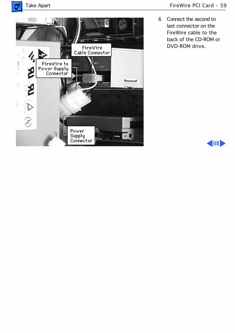
8/19/2019 Powermac Server g3 Minitower
http://slidepdf.com/reader/full/powermac-server-g3-minitower 176/292
Take Apart FireWire PCI Card - 5
6 Connect the second tolast connector on theFireWire cable to theback of the CD-ROM orDVD-ROM drive.
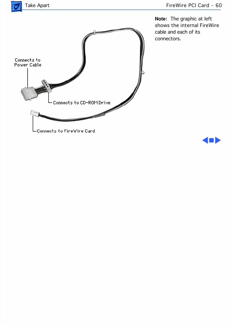
8/19/2019 Powermac Server g3 Minitower
http://slidepdf.com/reader/full/powermac-server-g3-minitower 177/292
Take Apart FireWire PCI Card - 6
Note: The graphic at leftshows the internal FireWirecable and each of itsconnectors.
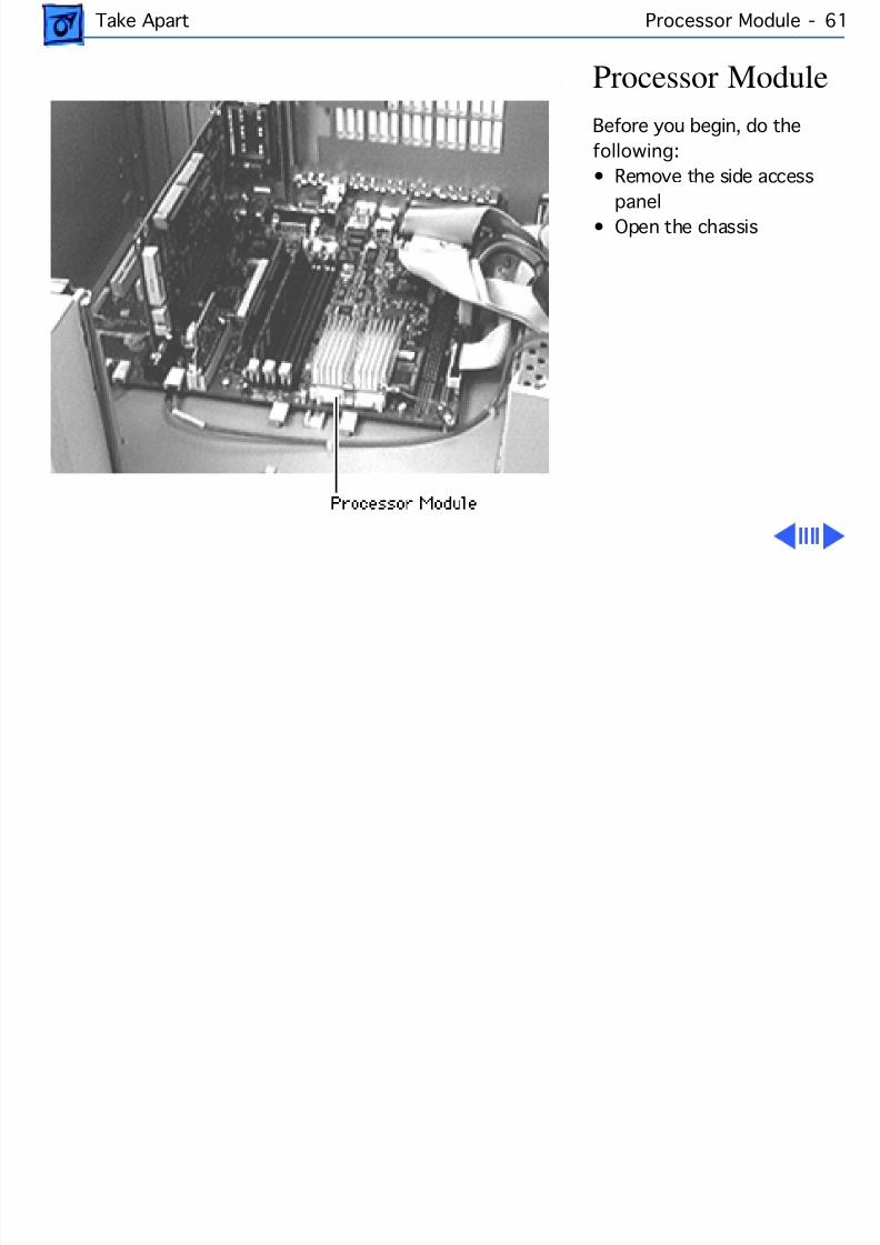
8/19/2019 Powermac Server g3 Minitower
http://slidepdf.com/reader/full/powermac-server-g3-minitower 178/292
Take Apart Processor Module - 61
Processor ModuleBefore you begin, do thefollowing:• Remove the side access
panel• Open the chassis
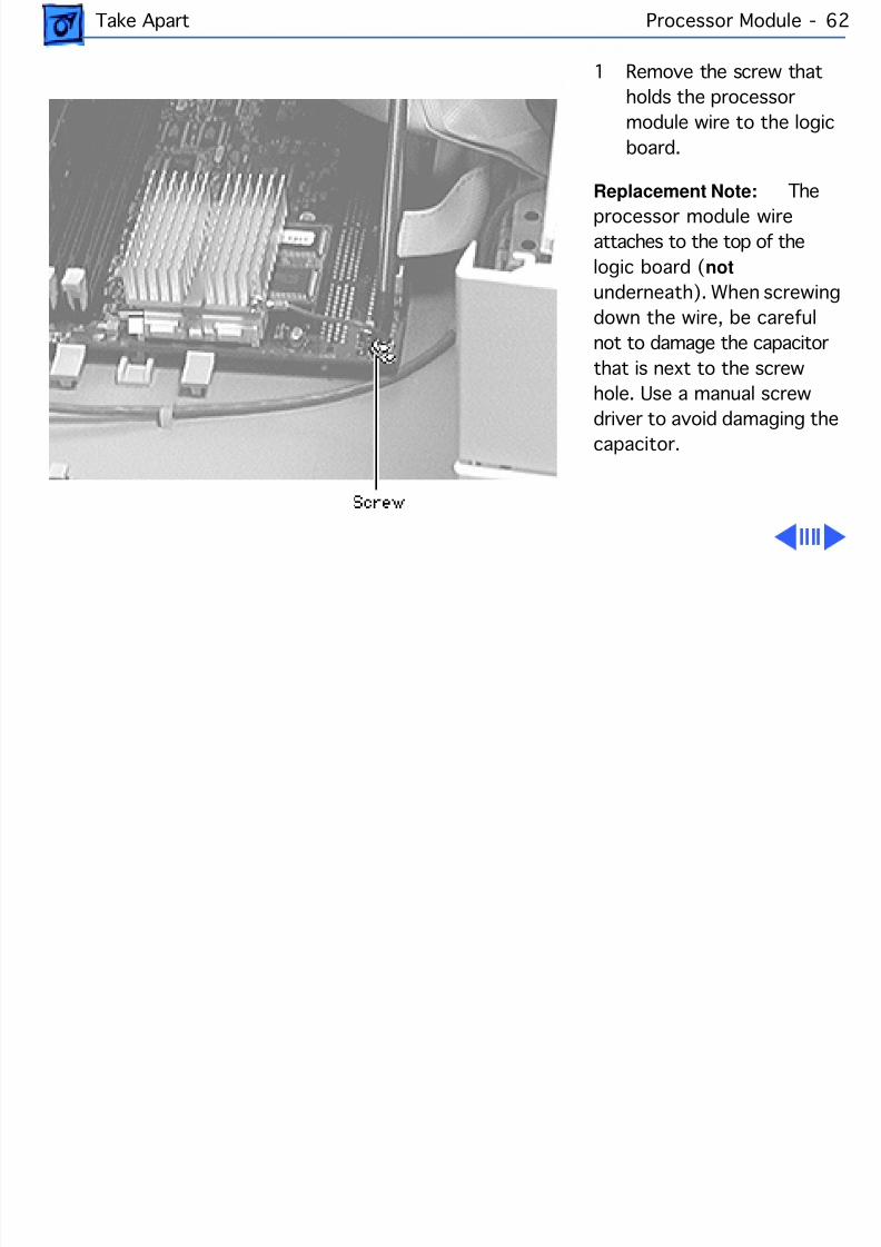
8/19/2019 Powermac Server g3 Minitower
http://slidepdf.com/reader/full/powermac-server-g3-minitower 179/292
Take Apart Processor Module - 62
1 Remove the screw thatholds the processormodule wire to the logicboard.
Replacement Note: Thprocessor module wireattaches to the top of thelogic board ( not underneath). When screwingdown the wire, be carefulnot to damage the capacitorthat is next to the screwhole. Use a manual screwdriver to avoid damaging thecapacitor.
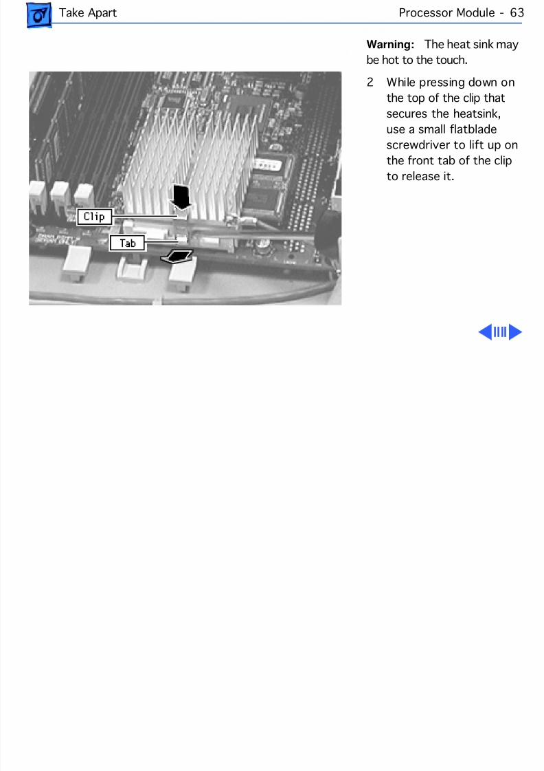
8/19/2019 Powermac Server g3 Minitower
http://slidepdf.com/reader/full/powermac-server-g3-minitower 180/292
Take Apart Processor Module - 63
Warning: The heat sink mabe hot to the touch.
2 While pressing down onthe top of the clip thatsecures the heatsink,
use a small flatbladescrewdriver to lift up onthe front tab of the clipto release it.
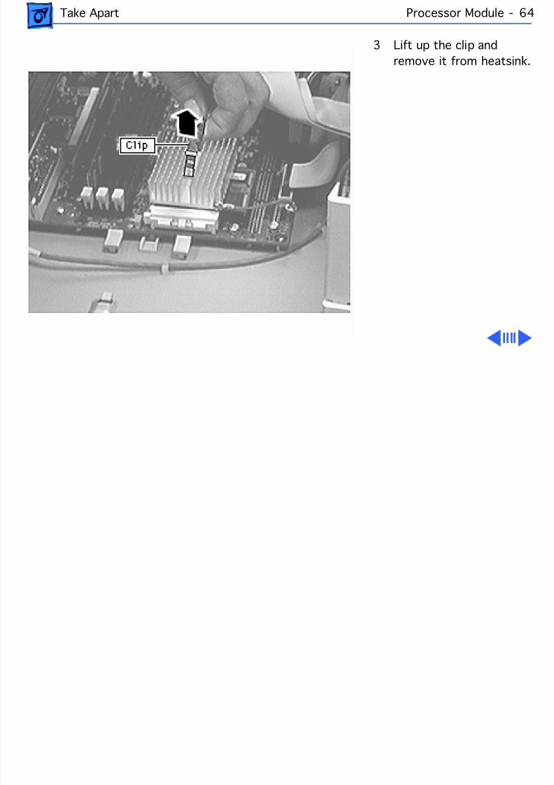
8/19/2019 Powermac Server g3 Minitower
http://slidepdf.com/reader/full/powermac-server-g3-minitower 181/292
Take Apart Processor Module - 64
3 Lift up the clip andremove it from heatsink
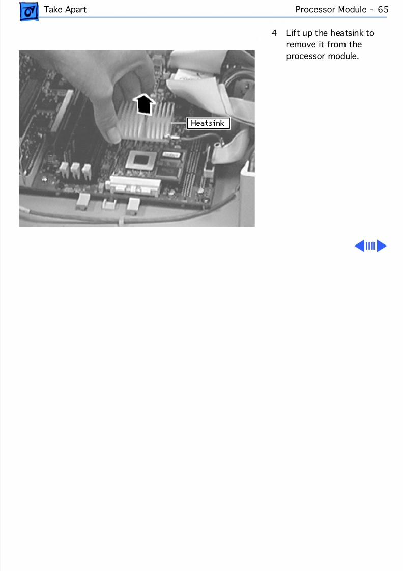
8/19/2019 Powermac Server g3 Minitower
http://slidepdf.com/reader/full/powermac-server-g3-minitower 182/292
Take Apart Processor Module - 65
4 Lift up the heatsink toremove it from theprocessor module.
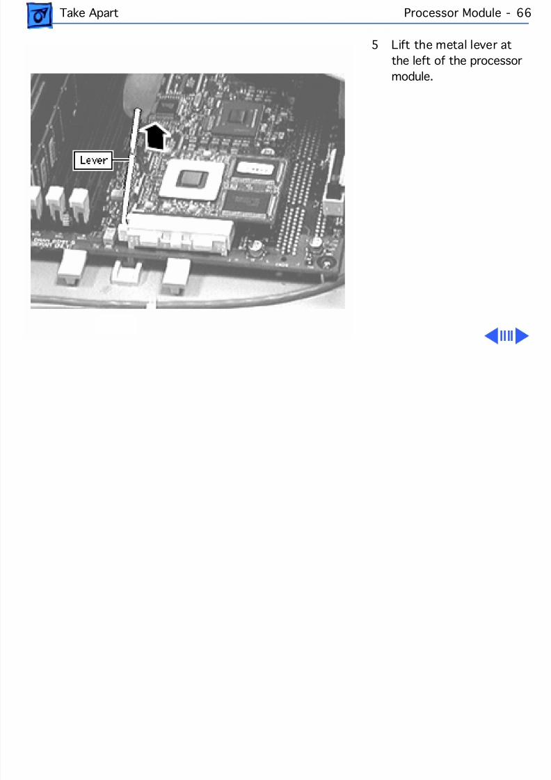
8/19/2019 Powermac Server g3 Minitower
http://slidepdf.com/reader/full/powermac-server-g3-minitower 183/292
Take Apart Processor Module - 66
5 Lift the metal lever atthe left of the processormodule.
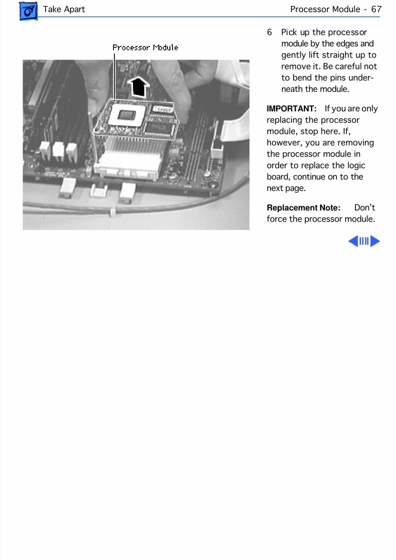
8/19/2019 Powermac Server g3 Minitower
http://slidepdf.com/reader/full/powermac-server-g3-minitower 184/292
Take Apart Processor Module - 67
6 Pick up the processormodule by the edges andgently lift straight up toremove it. Be careful notto bend the pins under-
neath the module.IMPORTANT: If you are onreplacing the processormodule, stop here. If,however, you are removingthe processor module inorder to replace the logicboard, continue on to thenext page.
Replacement Note: Doforce the processor module.
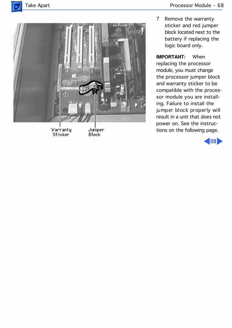
8/19/2019 Powermac Server g3 Minitower
http://slidepdf.com/reader/full/powermac-server-g3-minitower 185/292
Take Apart Processor Module - 68
7 Remove the warrantysticker and red jumperblock located next to thebattery if replacing thelogic board only.
IMPORTANT: Whenreplacing the processormodule, you must changethe processor jumper blockand warranty sticker to becompatible with the proces-sor module you are install-ing. Failure to install the
jumper block properly wilresult in a unit that does notpower on. See the instruc-tions on the following page.
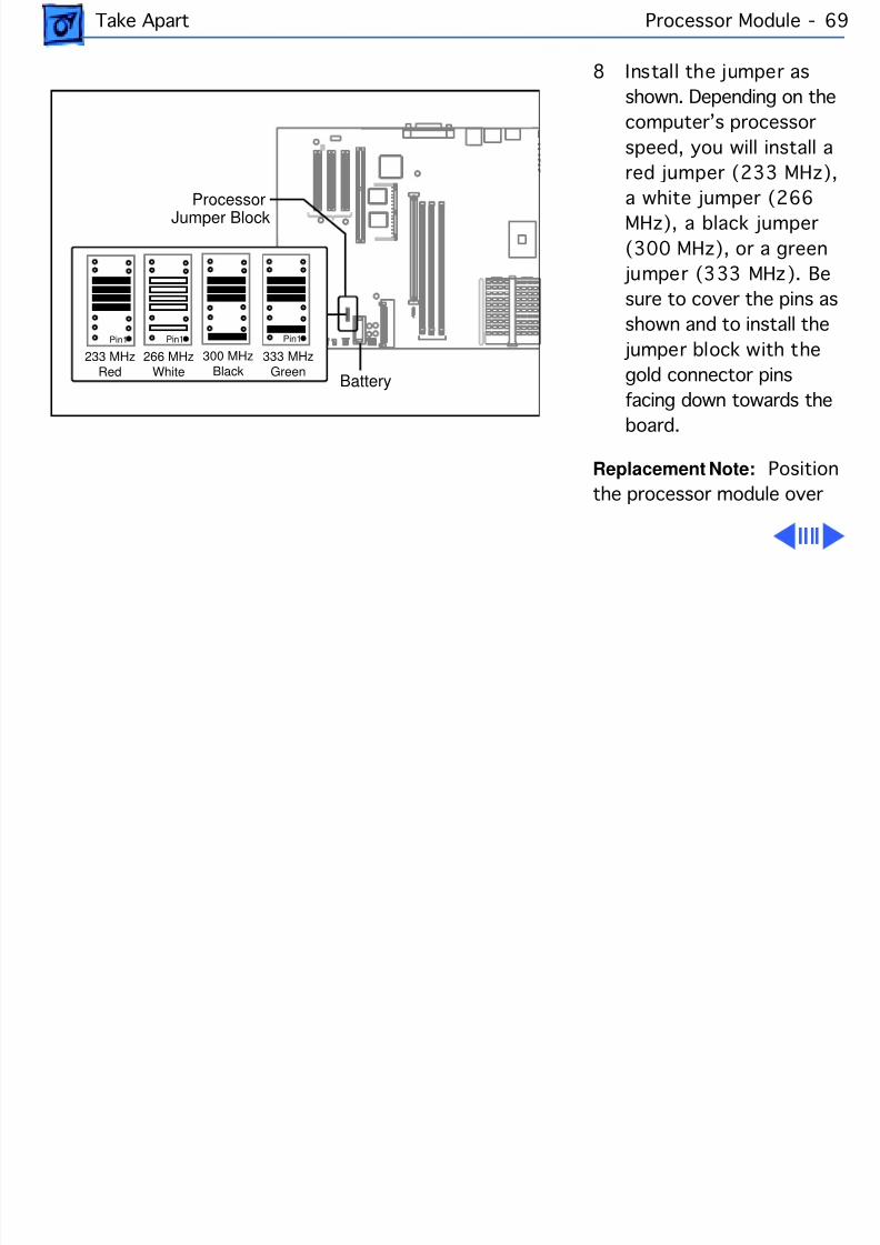
8/19/2019 Powermac Server g3 Minitower
http://slidepdf.com/reader/full/powermac-server-g3-minitower 186/292
Take Apart Processor Module - 69
8 Install the jumper asshown. Depending on thecomputer’s processorspeed, you will install ared jumper (233 MHz)
a white jumper (266MHz), a black jumper(300 MHz), or a green
jumper (333 MHz). Besure to cover the pins asshown and to install the
jumper block with thegold connector pinsfacing down towards theboard.
Replacement Note: Positthe processor module over
ProcessorJumper Block
Battery
233 MHzRed
266 MHzWhite
300 MHzBlack
Pin1 Pin1
333 MHzGreen
Pin1
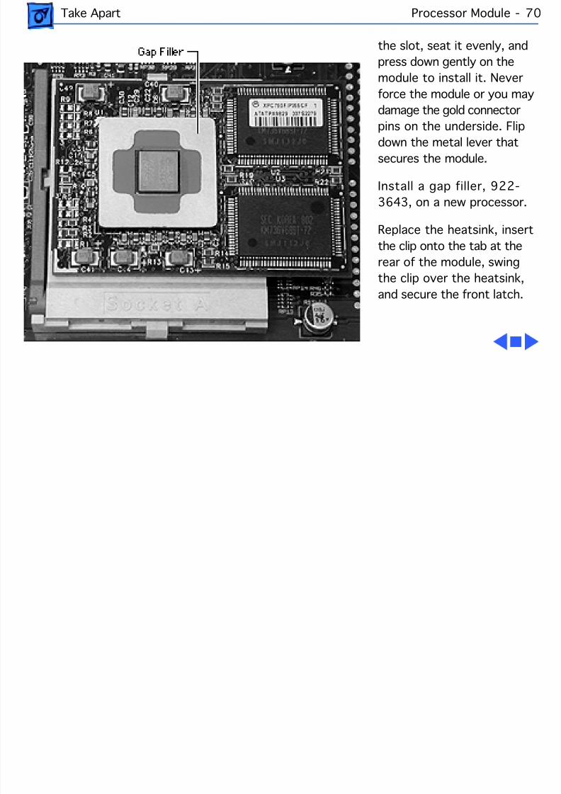
8/19/2019 Powermac Server g3 Minitower
http://slidepdf.com/reader/full/powermac-server-g3-minitower 187/292
Take Apart Processor Module - 70
the slot, seat it evenly, andpress down gently on themodule to install it. Neverforce the module or you maydamage the gold connector
pins on the underside. Flipdown the metal lever thatsecures the module.
Install a gap filler, 922-3643, on a new processor.
Replace the heatsink, insertthe clip onto the tab at the
rear of the module, swingthe clip over the heatsink,and secure the front latch.
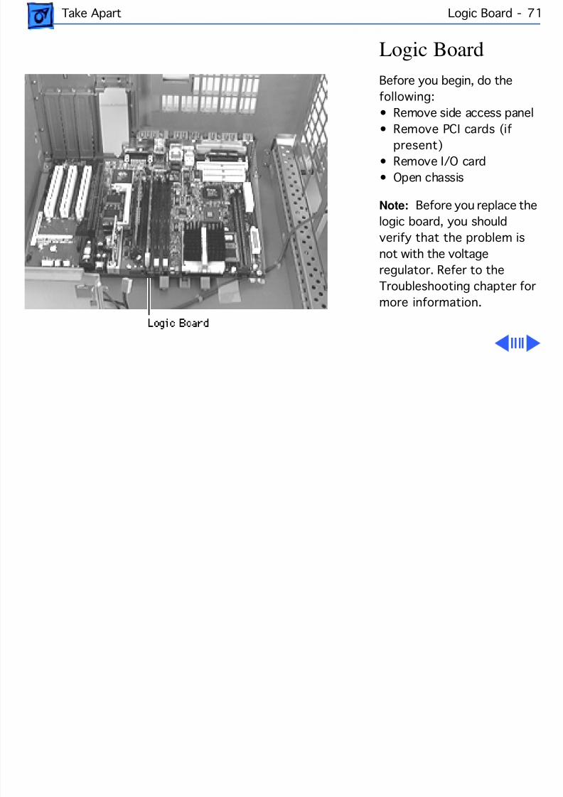
8/19/2019 Powermac Server g3 Minitower
http://slidepdf.com/reader/full/powermac-server-g3-minitower 188/292
Take Apart Logic Board - 7
Logic BoardBefore you begin, do thefollowing:• Remove side access panel
• Remove PCI cards (ifpresent)
• Remove I/O card• Open chassis
Note: Before you replace thelogic board, you shouldverify that the problem isnot with the voltageregulator. Refer to theTroubleshooting chapter formore information.
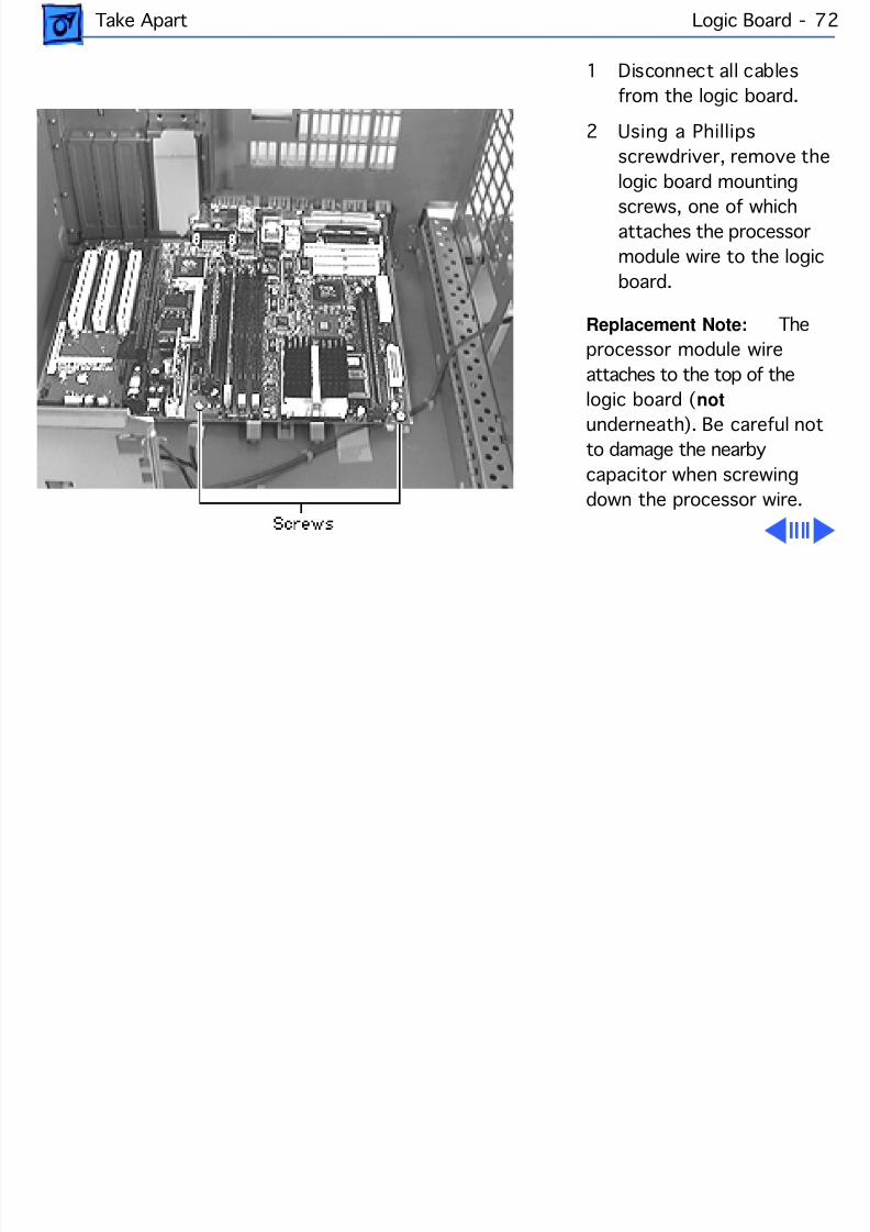
8/19/2019 Powermac Server g3 Minitower
http://slidepdf.com/reader/full/powermac-server-g3-minitower 189/292
Take Apart Logic Board - 7
1 Disconnect all cablesfrom the logic board.
2 Using a Phillipsscrewdriver, remove thelogic board mounting
screws, one of whichattaches the processormodule wire to the logicboard.
Replacement Note: Thprocessor module wireattaches to the top of the
logic board ( not underneath). Be careful notto damage the nearbycapacitor when screwingdown the processor wire.
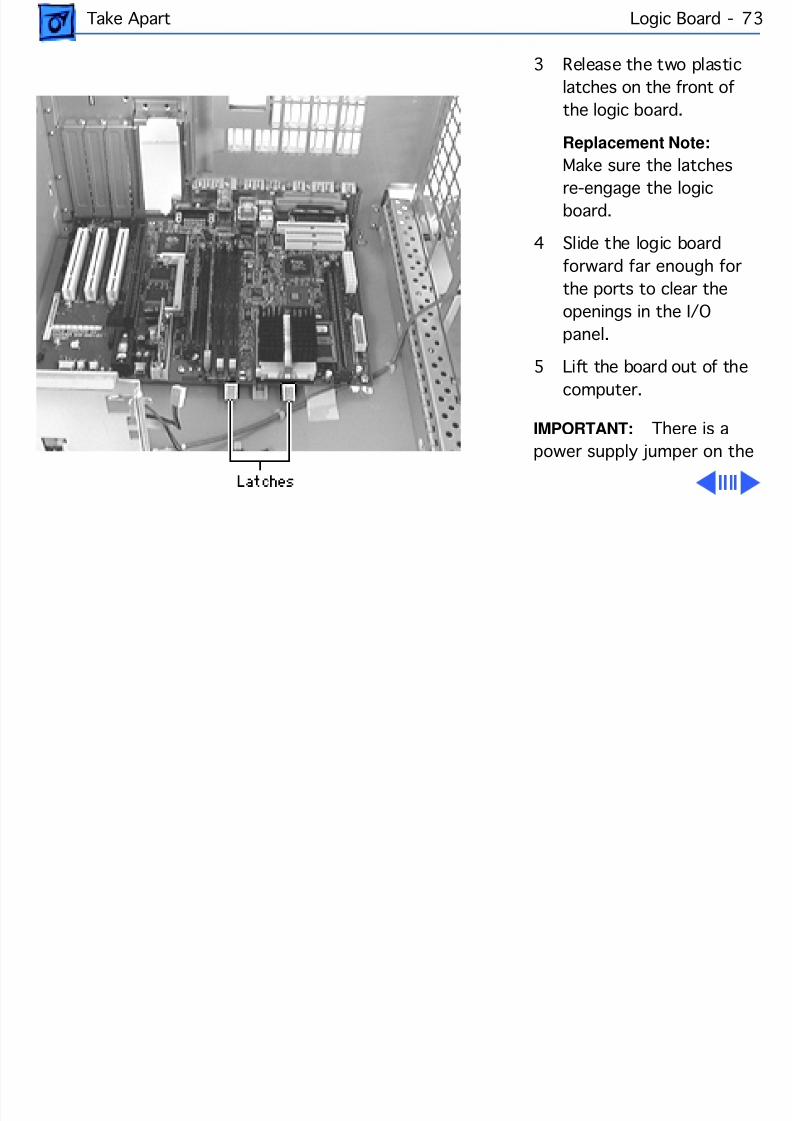
8/19/2019 Powermac Server g3 Minitower
http://slidepdf.com/reader/full/powermac-server-g3-minitower 190/292
Take Apart Logic Board - 7
3 Release the two plasticlatches on the front ofthe logic board.
Replacement Note:Make sure the latches
re-engage the logicboard.
4 Slide the logic boardforward far enough forthe ports to clear theopenings in the I/Opanel.
5 Lift the board out of thecomputer.
IMPORTANT: There is apower supply jumper on the
8/19/2019 Powermac Server g3 Minitower
http://slidepdf.com/reader/full/powermac-server-g3-minitower 191/292
Take Apart Logic Board - 7
logic board at J28 (near the PCI slots). If the logic board isinstalled in the PM G3 Minitower, this jumper must coverthe pins marked “PS”. Failure to install this jumpercorrectly will result in a computer that will not boot up.
Note: Replacement logic boards come with the J28 jumperpre-installed in the PM G3 Desktop configuration; that is,the jumper comes installed on the “Mac” pins. If you areinstalling the logic board in a Power Mac G3 Minitower orServer G3 unit, you must move the J28 jumper to cover the“PS” pins. When replacing the logic board, be sure to checkthe power supply jumper setting.
IMPORTANT: If you are replacing the logic board, you must
transfer the processor module and processor jumper (atJ16) from the original logic board to the replacement board.See the take-apart instructions for the “Processor Module”for more information. You must also cover the processor
8/19/2019 Powermac Server g3 Minitower
http://slidepdf.com/reader/full/powermac-server-g3-minitower 192/292
Take Apart Logic Board - 7
jumper with a new warranty sticker, which comes with thereplacement logic board. This sticker must be in place toprotect the customer’s product warranty.
IMPORTANT: If you are replacing the logic board and the newlogic board does not come with a voltage regulator, youmust transfer the voltage regulator from the old logic boardto the new board.
Note: Before returning the logic board to Apple, remove theprocessor module, processor jumper block and warrantysticker, DRAM, SGRAM, the I/O card, and any PCI cards (ifpresent). Do NOT remove the voltage regulator or ROMDIMM.
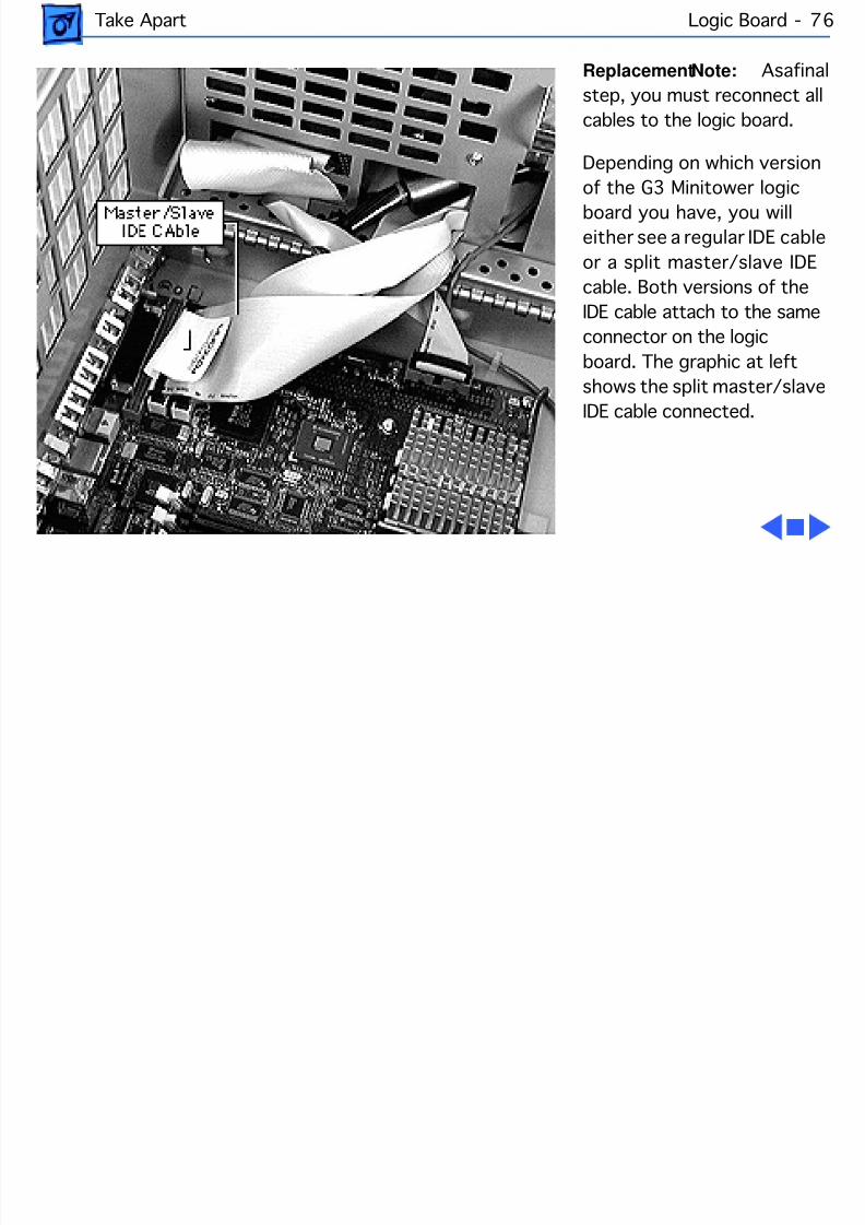
8/19/2019 Powermac Server g3 Minitower
http://slidepdf.com/reader/full/powermac-server-g3-minitower 193/292
Take Apart Logic Board - 7
Replacement Note: As a fstep, you must reconnect allcables to the logic board.
Depending on which versionof the G3 Minitower logicboard you have, you willeither see a regular IDE cableor a split master/slave IDEcable. Both versions of theIDE cable attach to the sameconnector on the logicboard. The graphic at leftshows the split master/slaveIDE cable connected.
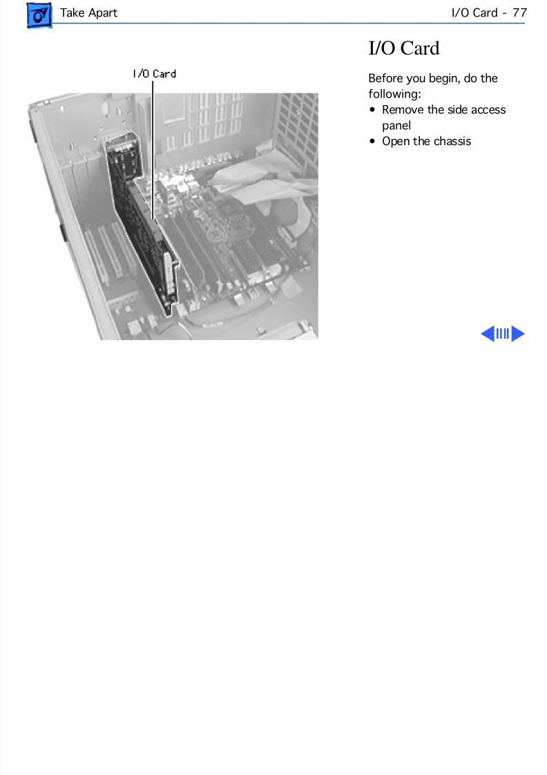
8/19/2019 Powermac Server g3 Minitower
http://slidepdf.com/reader/full/powermac-server-g3-minitower 194/292
Take Apart I/O Card - 7
I/O CardBefore you begin, do thefollowing:• Remove the side access
panel• Open the chassis
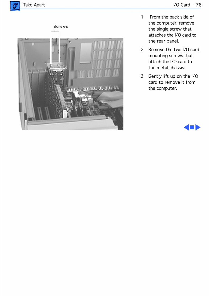
8/19/2019 Powermac Server g3 Minitower
http://slidepdf.com/reader/full/powermac-server-g3-minitower 195/292
Take Apart I/O Card - 7
1 From the back side ofthe computer, removethe single screw thatattaches the I/O card tothe rear panel.
2 Remove the two I/O cardmounting screws thatattach the I/O card tothe metal chassis.
3 Gently lift up on the I/Ocard to remove it fromthe computer.
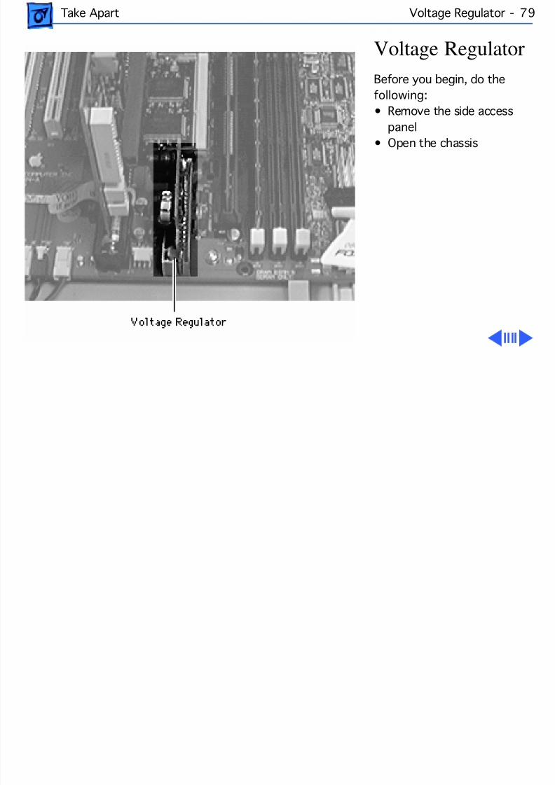
8/19/2019 Powermac Server g3 Minitower
http://slidepdf.com/reader/full/powermac-server-g3-minitower 196/292
Take Apart Voltage Regulator - 79
Voltage RegulatorBefore you begin, do thefollowing:• Remove the side access
panel• Open the chassis
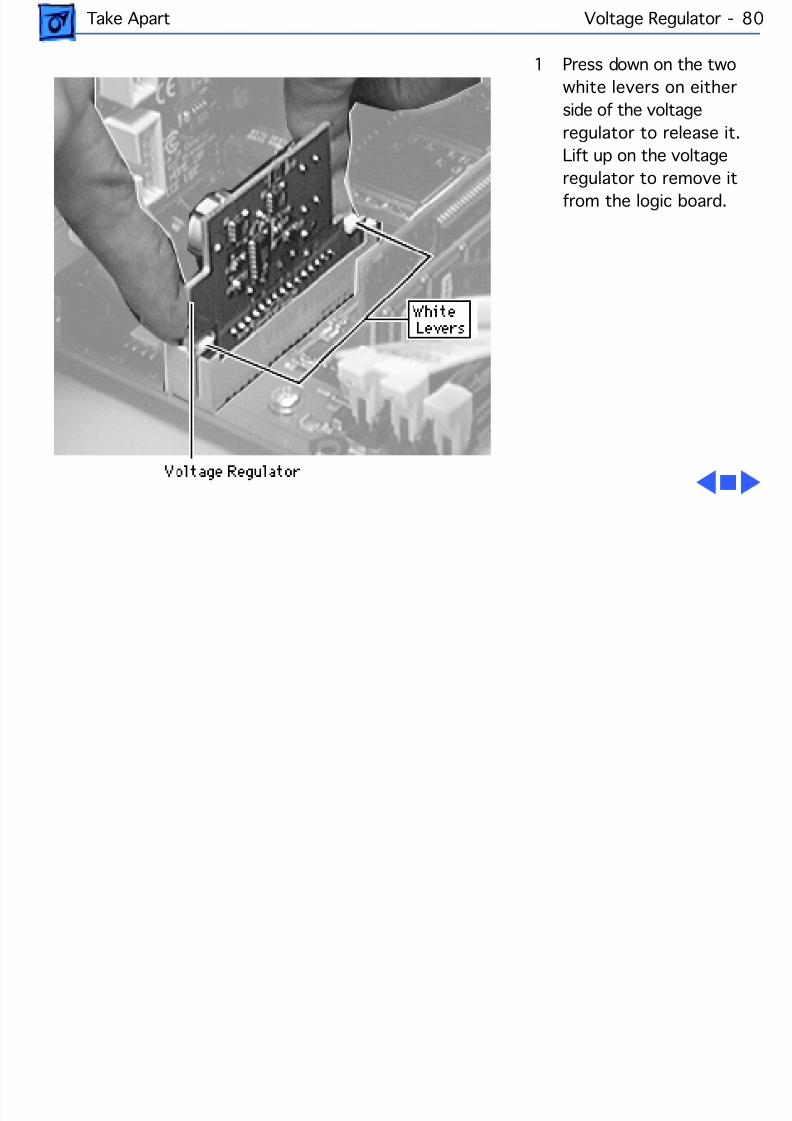
8/19/2019 Powermac Server g3 Minitower
http://slidepdf.com/reader/full/powermac-server-g3-minitower 197/292
Take Apart Voltage Regulator - 80
1 Press down on the twowhite levers on eitherside of the voltageregulator to release it.Lift up on the voltage
regulator to remove itfrom the logic board.
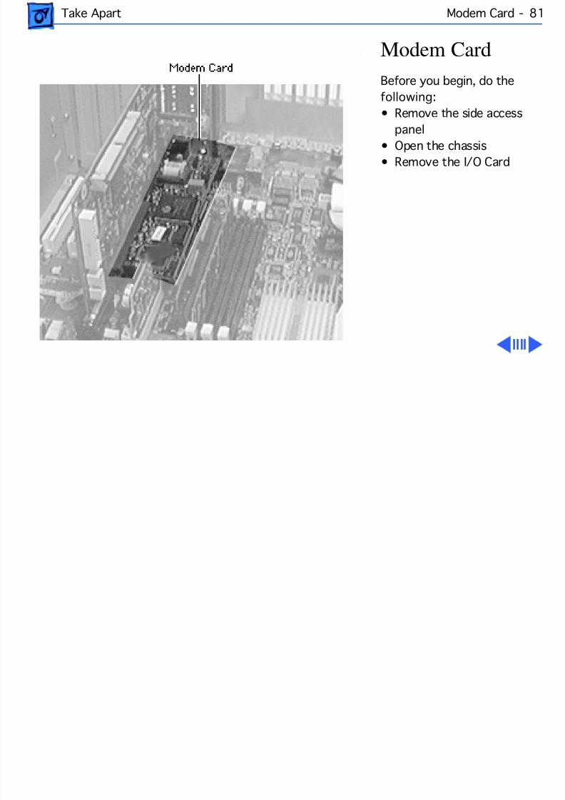
8/19/2019 Powermac Server g3 Minitower
http://slidepdf.com/reader/full/powermac-server-g3-minitower 198/292
Take Apart Modem Card - 8
Modem CardBefore you begin, do thefollowing:• Remove the side access
panel• Open the chassis• Remove the I/O Card
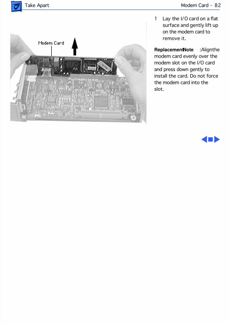
8/19/2019 Powermac Server g3 Minitower
http://slidepdf.com/reader/full/powermac-server-g3-minitower 199/292
Take Apart Modem Card - 8
1 Lay the I/O card on a flatsurface and gently lift upon the modem card toremove it.
Replacement Note : Aligmodem card evenly over themodem slot on the I/O cardand press down gently toinstall the card. Do not forcethe modem card into theslot.
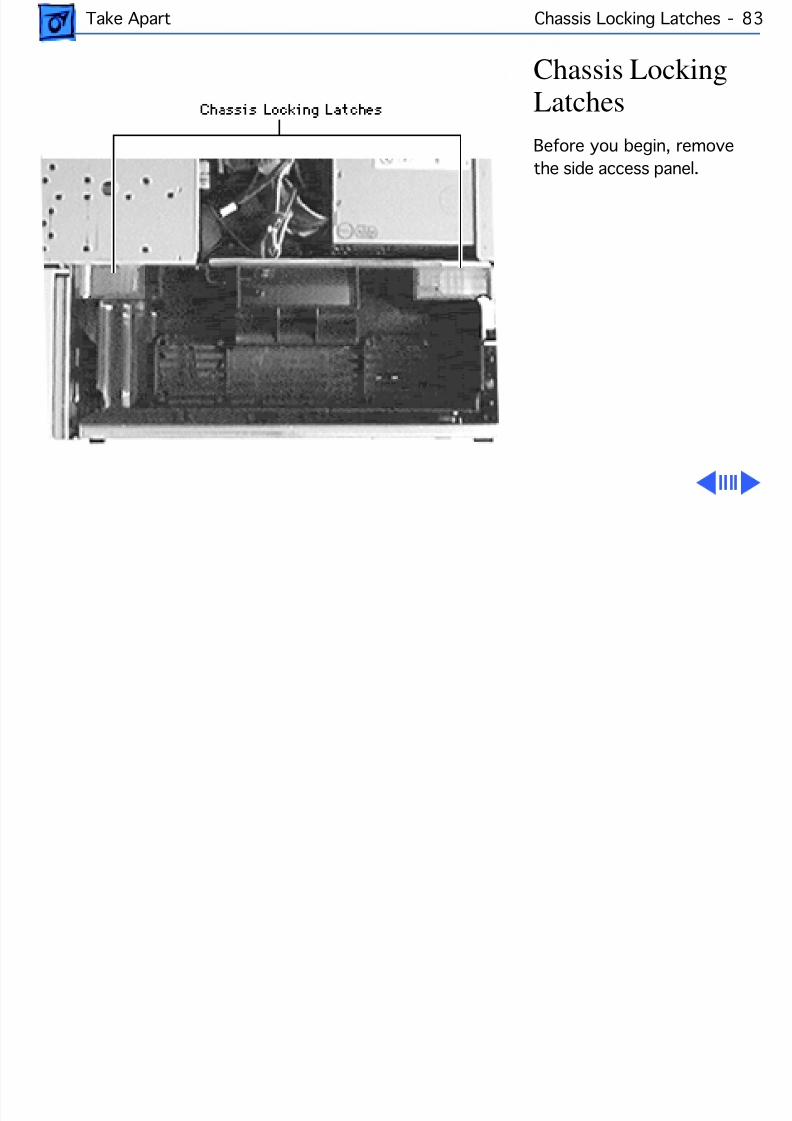
8/19/2019 Powermac Server g3 Minitower
http://slidepdf.com/reader/full/powermac-server-g3-minitower 200/292
Take Apart Chassis Locking Latches - 83
Chassis LockingLatchesBefore you begin, removethe side access panel.
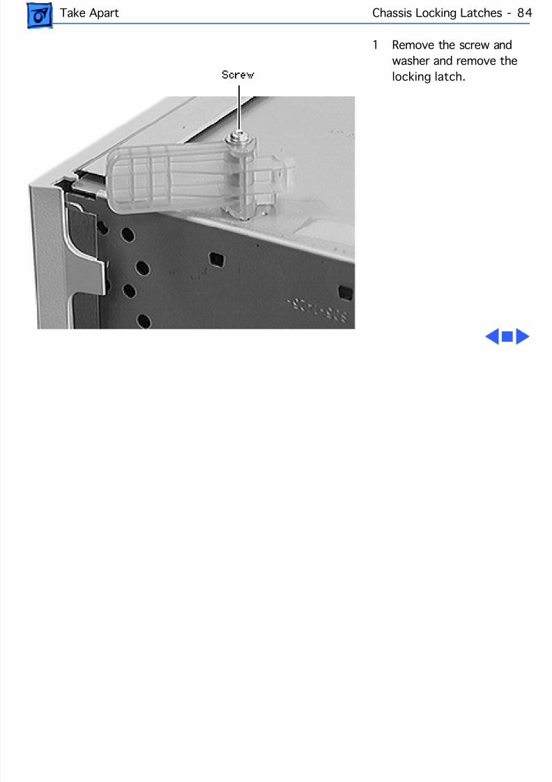
8/19/2019 Powermac Server g3 Minitower
http://slidepdf.com/reader/full/powermac-server-g3-minitower 201/292
Take Apart Chassis Locking Latches - 84
1 Remove the screw andwasher and remove thelocking latch.
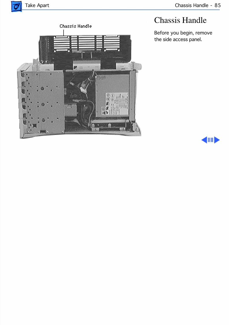
8/19/2019 Powermac Server g3 Minitower
http://slidepdf.com/reader/full/powermac-server-g3-minitower 202/292
Take Apart Chassis Handle - 8
Chassis HandleBefore you begin, removethe side access panel.
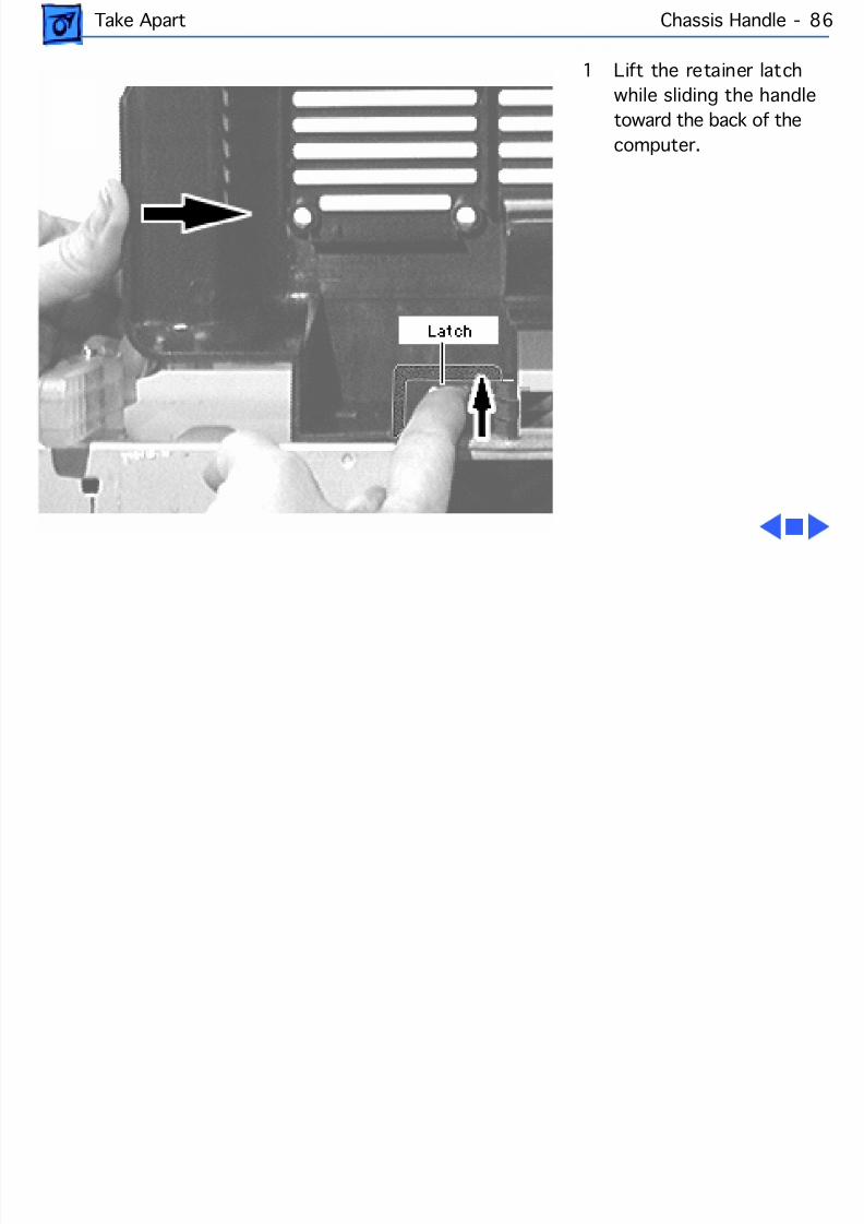
8/19/2019 Powermac Server g3 Minitower
http://slidepdf.com/reader/full/powermac-server-g3-minitower 203/292
Take Apart Chassis Handle - 8
1 Lift the retainer latchwhile sliding the handletoward the back of thecomputer.
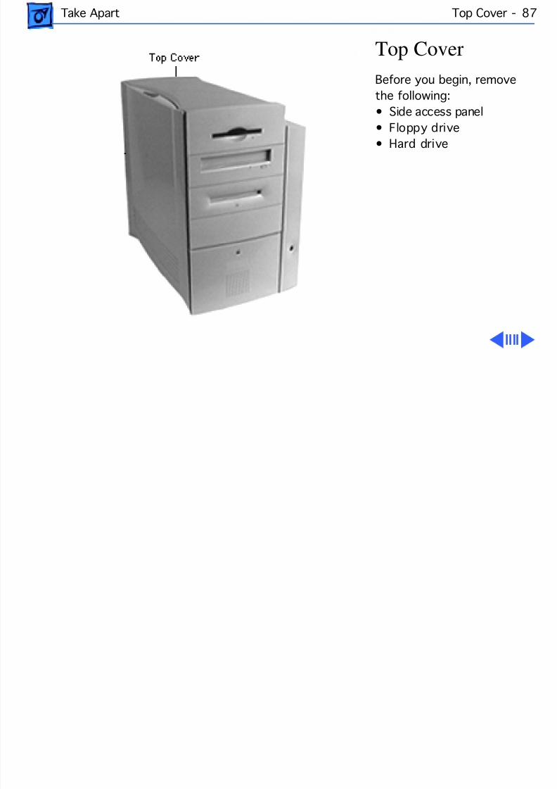
8/19/2019 Powermac Server g3 Minitower
http://slidepdf.com/reader/full/powermac-server-g3-minitower 204/292
Take Apart Top Cover - 8
Top CoverBefore you begin, removethe following:• Side access panel
• Floppy drive• Hard drive
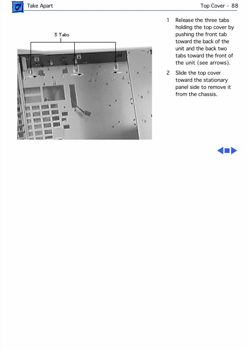
8/19/2019 Powermac Server g3 Minitower
http://slidepdf.com/reader/full/powermac-server-g3-minitower 205/292
Take Apart Top Cover - 8
1 Release the three tabsholding the top cover bypushing the front tabtoward the back of theunit and the back two
tabs toward the front ofthe unit (see arrows).
2 Slide the top covertoward the stationarypanel side to remove itfrom the chassis.
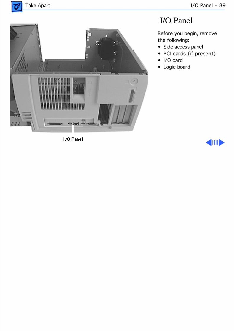
8/19/2019 Powermac Server g3 Minitower
http://slidepdf.com/reader/full/powermac-server-g3-minitower 206/292
Take Apart I/O Panel - 8
I/O PanelBefore you begin, removethe following:• Side access panel
• PCI cards (if present)• I/O card• Logic board
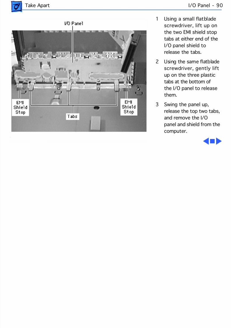
8/19/2019 Powermac Server g3 Minitower
http://slidepdf.com/reader/full/powermac-server-g3-minitower 207/292
Take Apart I/O Panel - 9
1 Using a small flatbladescrewdriver, lift up onthe two EMI shield stoptabs at either end of theI/O panel shield to
release the tabs.2 Using the same flatblade
screwdriver, gently liftup on the three plastictabs at the bottom ofthe I/O panel to releasethem.
3 Swing the panel up,release the top two tabs,and remove the I/Opanel and shield from thecomputer.
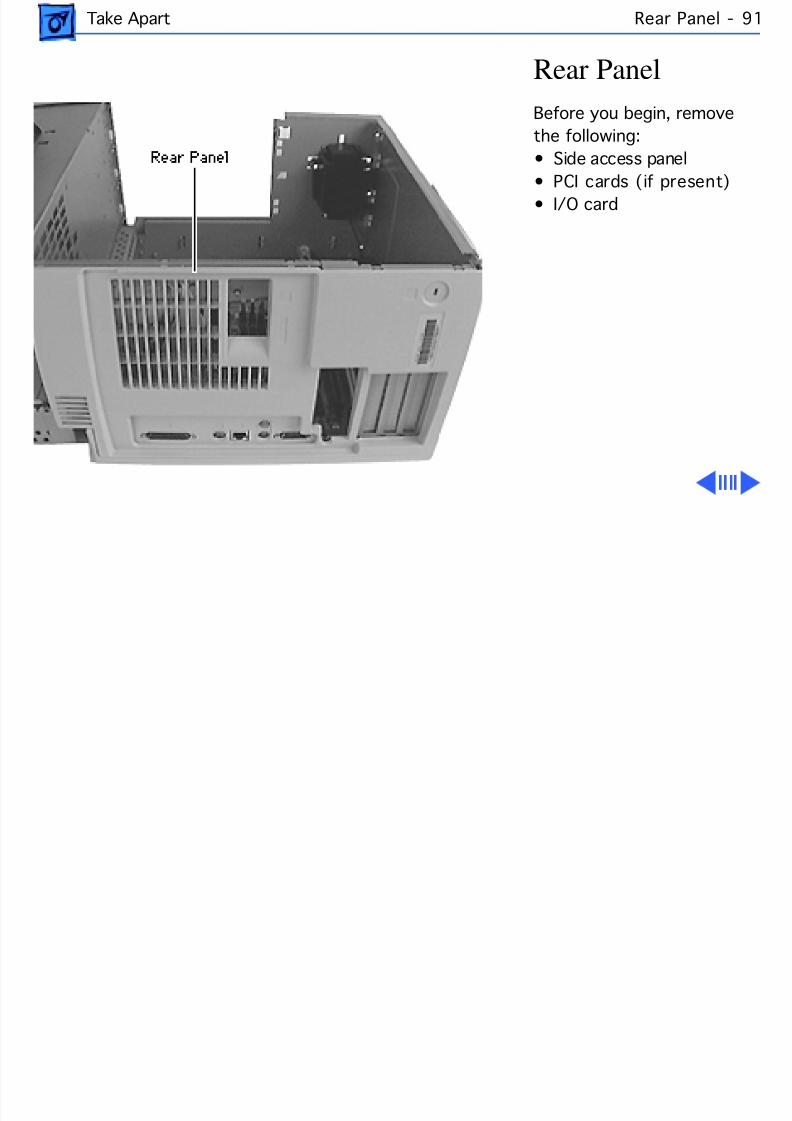
8/19/2019 Powermac Server g3 Minitower
http://slidepdf.com/reader/full/powermac-server-g3-minitower 208/292
Take Apart Rear Panel - 9
Rear PanelBefore you begin, removethe following:• Side access panel
• PCI cards (if present)• I/O card
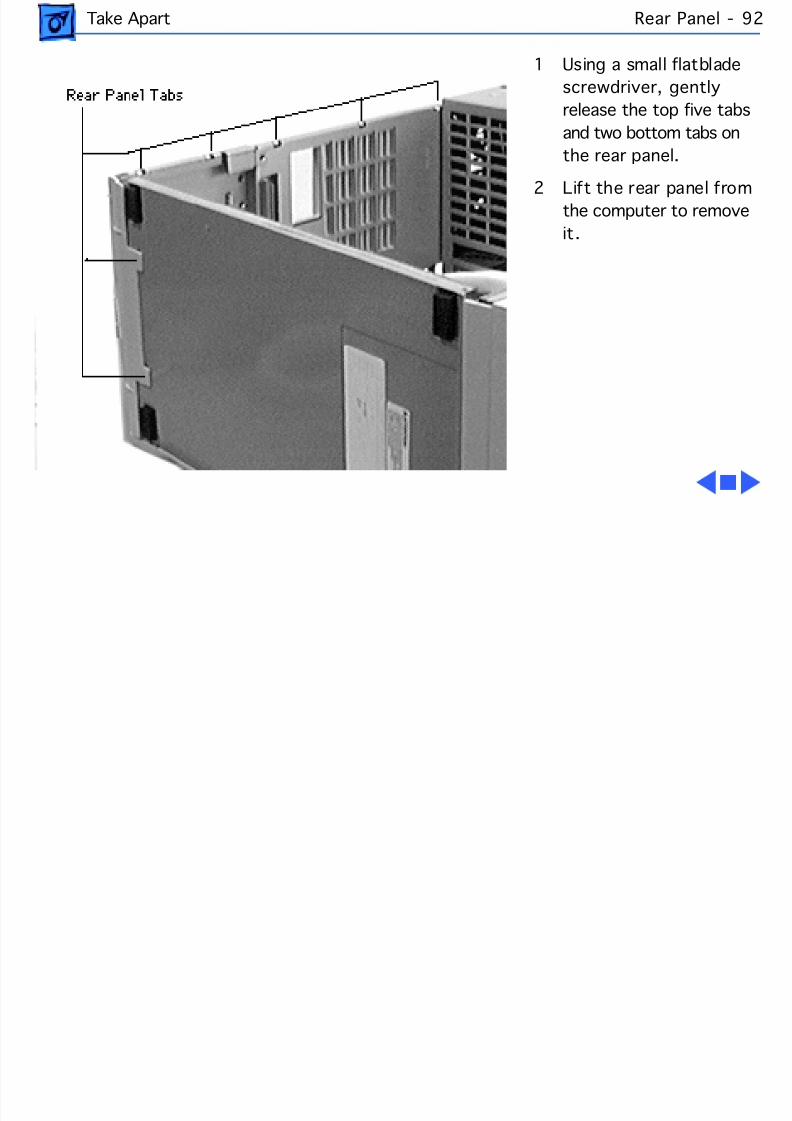
8/19/2019 Powermac Server g3 Minitower
http://slidepdf.com/reader/full/powermac-server-g3-minitower 209/292
Take Apart Rear Panel - 9
1 Using a small flatbladescrewdriver, gentlyrelease the top five tabsand two bottom tabs onthe rear panel.
2 Lift the rear panel fromthe computer to removeit.
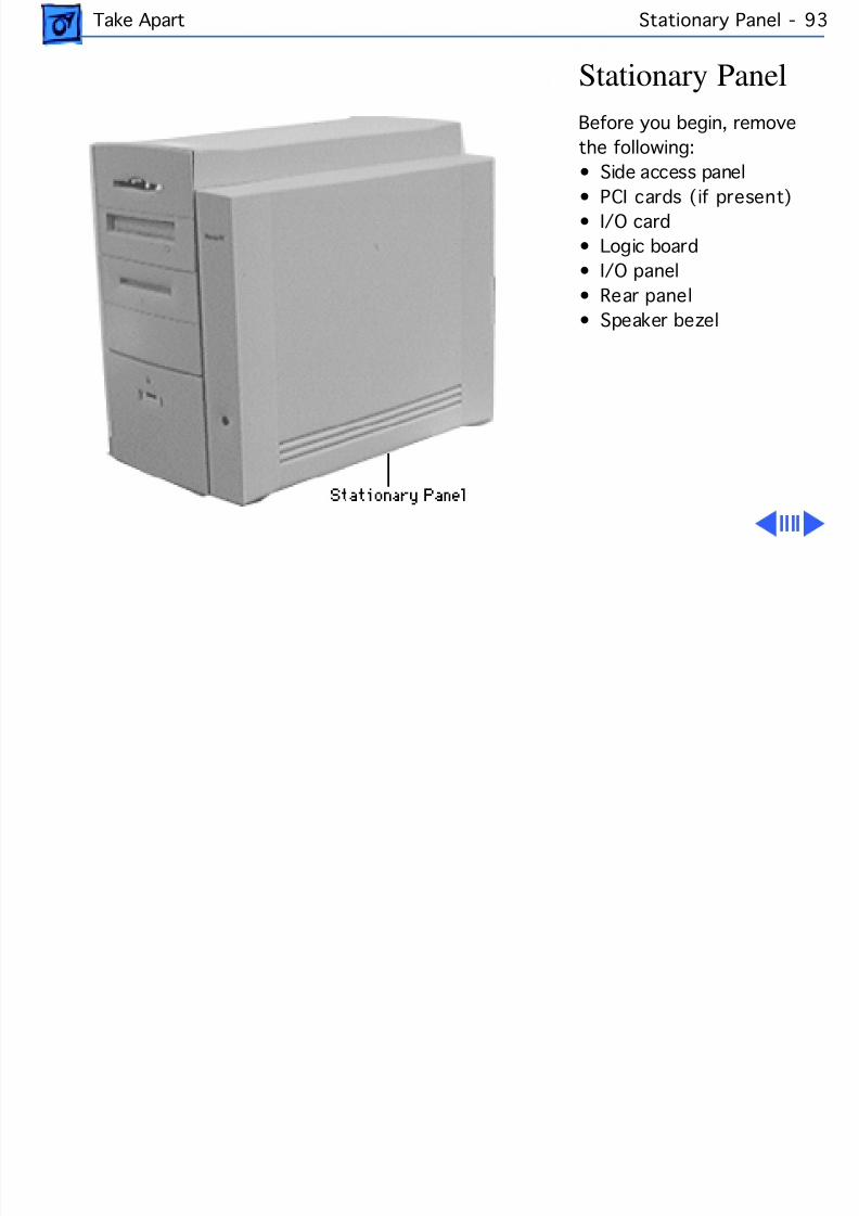
8/19/2019 Powermac Server g3 Minitower
http://slidepdf.com/reader/full/powermac-server-g3-minitower 210/292
Take Apart Stationary Panel - 93
Stationary PanelBefore you begin, removethe following:• Side access panel
• PCI cards (if present)• I/O card• Logic board• I/O panel• Rear panel• Speaker bezel
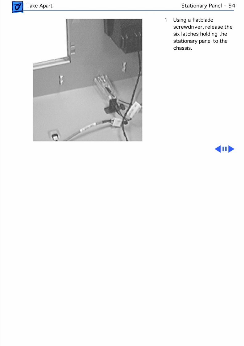
8/19/2019 Powermac Server g3 Minitower
http://slidepdf.com/reader/full/powermac-server-g3-minitower 211/292
Take Apart Stationary Panel - 94
1 Using a flatbladescrewdriver, release thesix latches holding thestationary panel to thechassis.

8/19/2019 Powermac Server g3 Minitower
http://slidepdf.com/reader/full/powermac-server-g3-minitower 212/292
Take Apart Stationary Panel - 95
2 Lift the chassis slightly and slide the stationary panelforward.
3 Push the light/power actuator in toward the case so thatit is released from the stationary panel.
4 Remove the panel from the computer.
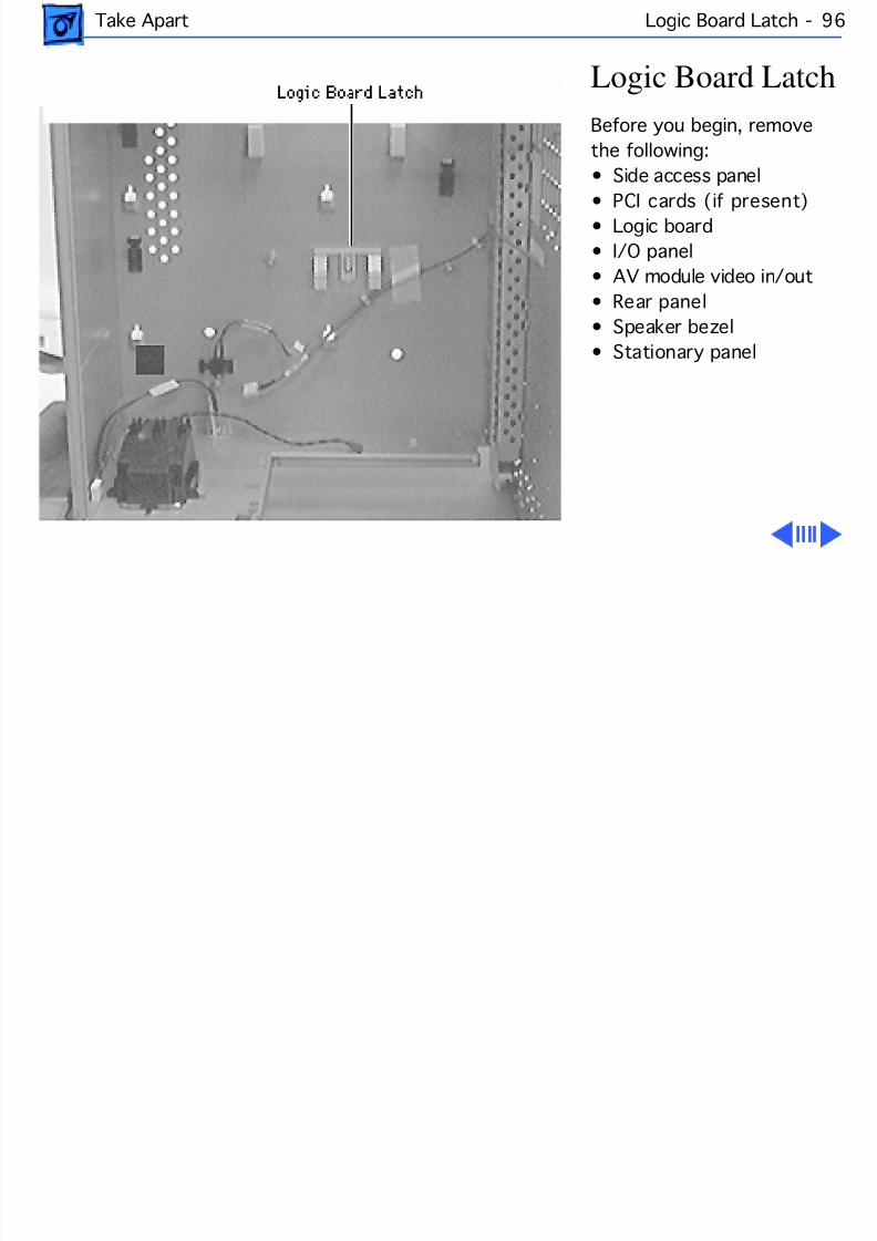
8/19/2019 Powermac Server g3 Minitower
http://slidepdf.com/reader/full/powermac-server-g3-minitower 213/292
Take Apart Logic Board Latch - 96
Logic Board LatchBefore you begin, removethe following:• Side access panel
• PCI cards (if present)• Logic board• I/O panel• AV module video in/out• Rear panel• Speaker bezel• Stationary panel
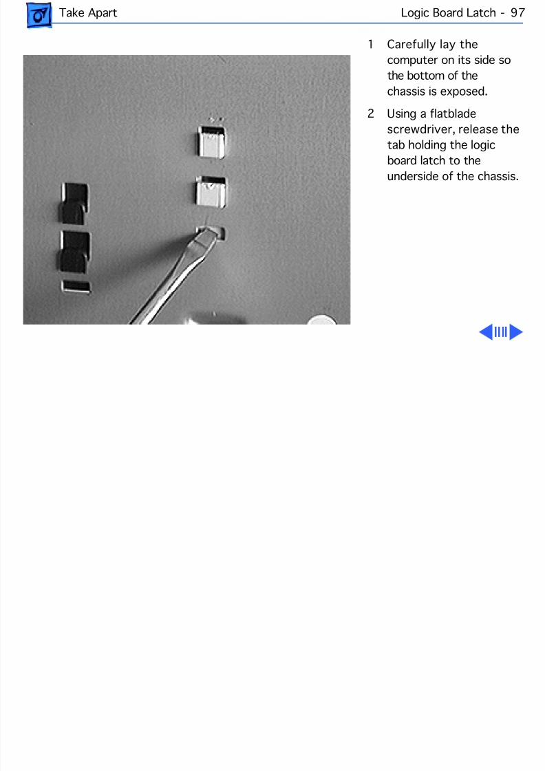
8/19/2019 Powermac Server g3 Minitower
http://slidepdf.com/reader/full/powermac-server-g3-minitower 214/292
Take Apart Logic Board Latch - 97
1 Carefully lay thecomputer on its side sothe bottom of thechassis is exposed.
2 Using a flatblade
screwdriver, release thetab holding the logicboard latch to theunderside of the chassis.
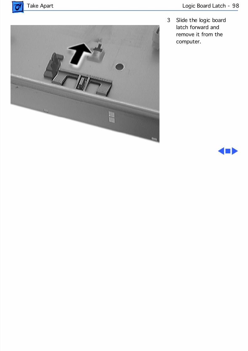
8/19/2019 Powermac Server g3 Minitower
http://slidepdf.com/reader/full/powermac-server-g3-minitower 215/292
Take Apart Logic Board Latch - 98
3 Slide the logic boardlatch forward andremove it from thecomputer.
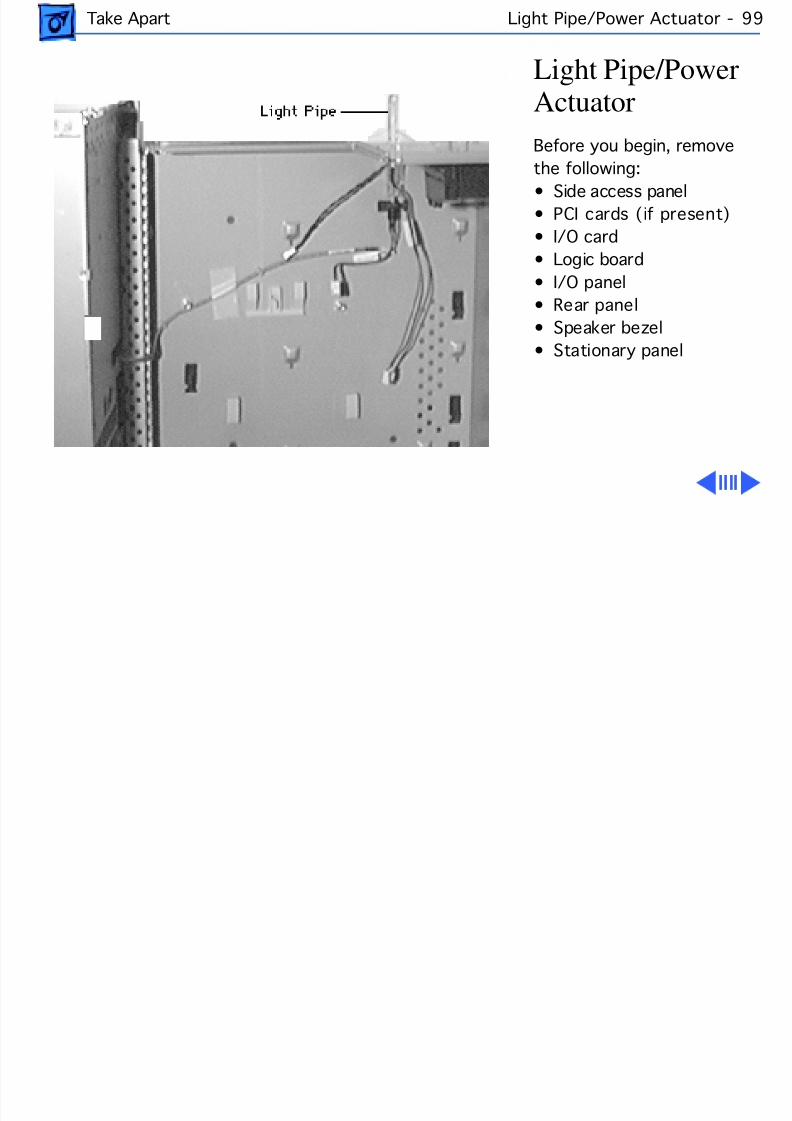
8/19/2019 Powermac Server g3 Minitower
http://slidepdf.com/reader/full/powermac-server-g3-minitower 216/292
Take Apart Light Pipe/Power Actuator - 99
Light Pipe/PowerActuatorBefore you begin, removethe following:• Side access panel• PCI cards (if present)• I/O card• Logic board• I/O panel• Rear panel• Speaker bezel• Stationary panel
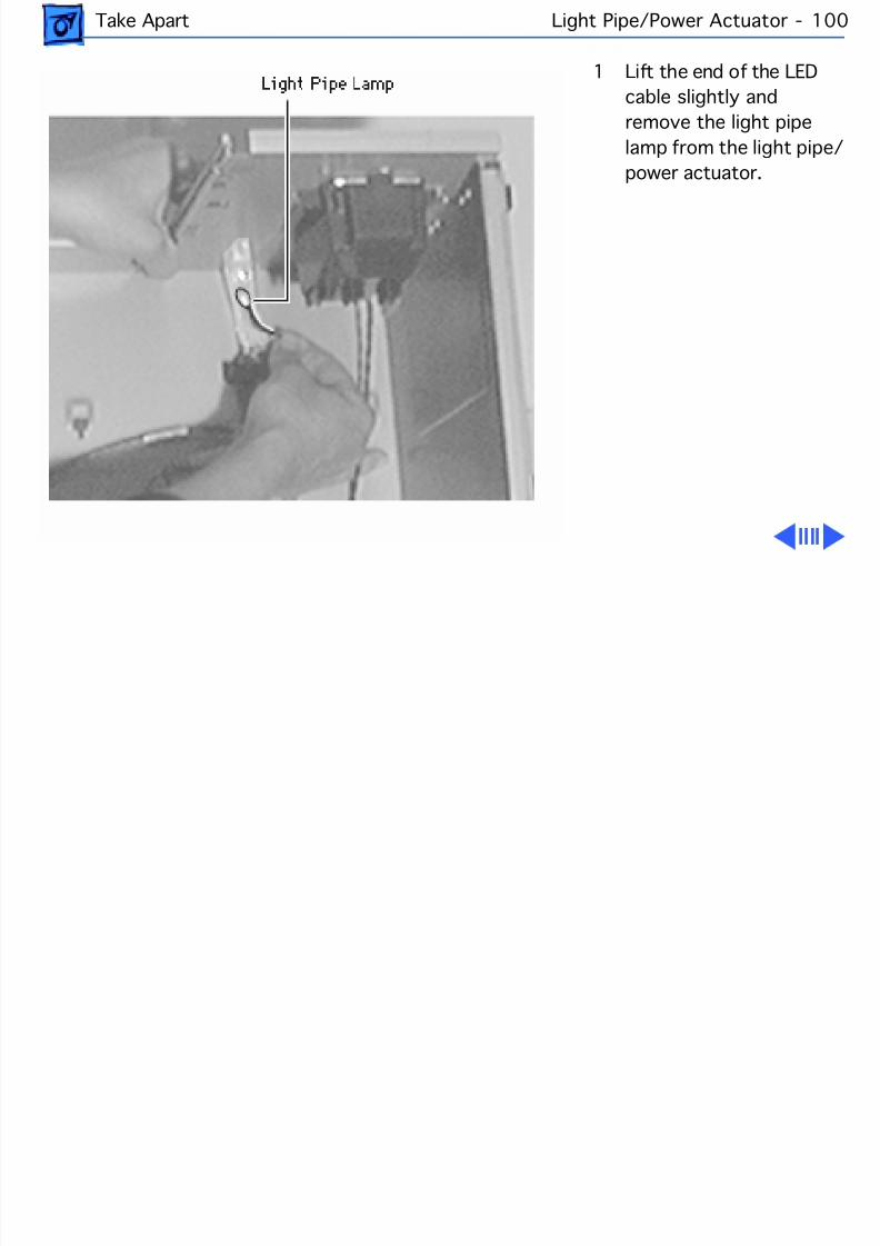
8/19/2019 Powermac Server g3 Minitower
http://slidepdf.com/reader/full/powermac-server-g3-minitower 217/292
Take Apart Light Pipe/Power Actuator - 100
1 Lift the end of the LEDcable slightly andremove the light pipelamp from the light pipepower actuator.
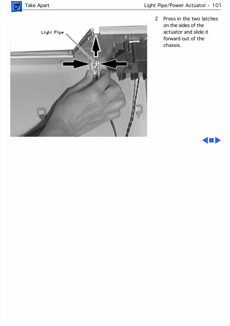
8/19/2019 Powermac Server g3 Minitower
http://slidepdf.com/reader/full/powermac-server-g3-minitower 218/292
Take Apart Light Pipe/Power Actuator - 101
2 Press in the two latcheson the sides of theactuator and slide itforward out of thechassis.
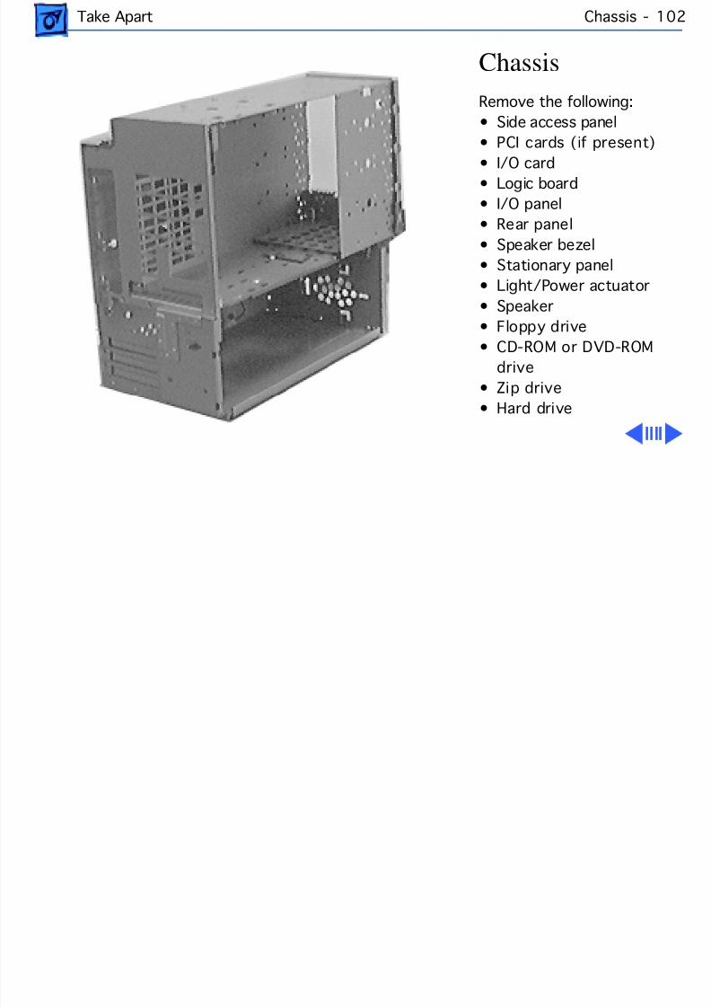
8/19/2019 Powermac Server g3 Minitower
http://slidepdf.com/reader/full/powermac-server-g3-minitower 219/292
Take Apart Chassis - 10
ChassisRemove the following:• Side access panel• PCI cards (if present)
• I/O card• Logic board• I/O panel• Rear panel• Speaker bezel• Stationary panel• Light/Power actuator• Speaker
• Floppy drive• CD-ROM or DVD-ROMdrive
• Zip drive• Hard drive
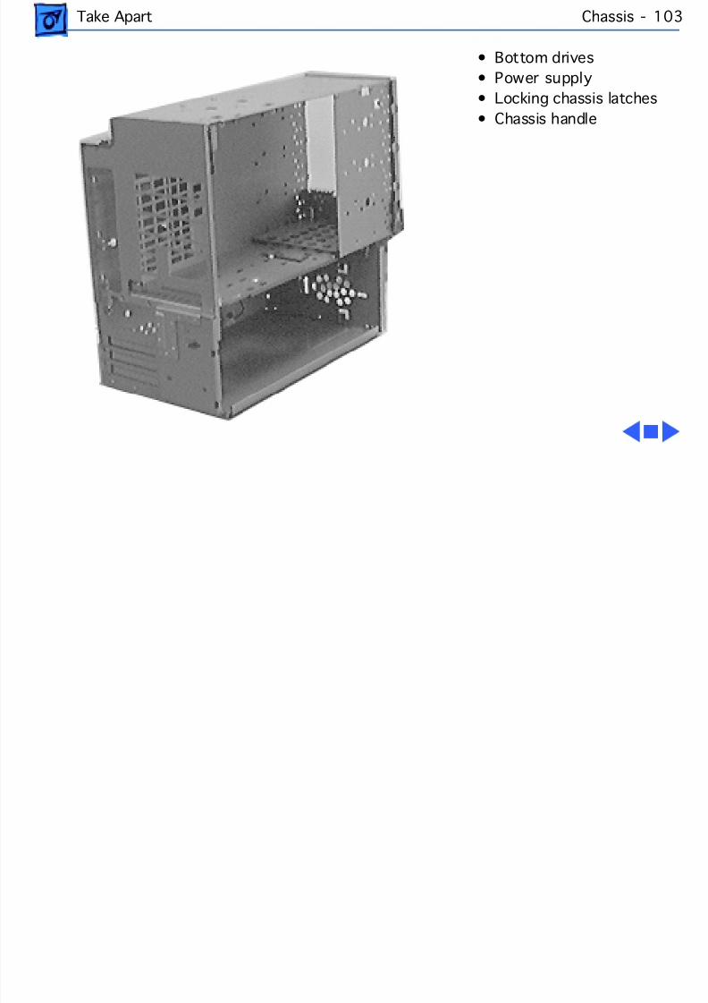
8/19/2019 Powermac Server g3 Minitower
http://slidepdf.com/reader/full/powermac-server-g3-minitower 220/292
Take Apart Chassis - 10
• Bottom drives• Power supply• Locking chassis latches• Chassis handle

8/19/2019 Powermac Server g3 Minitower
http://slidepdf.com/reader/full/powermac-server-g3-minitower 221/292
Service SourcK
UpgradePower Macintosh/Server G3
Minitowe
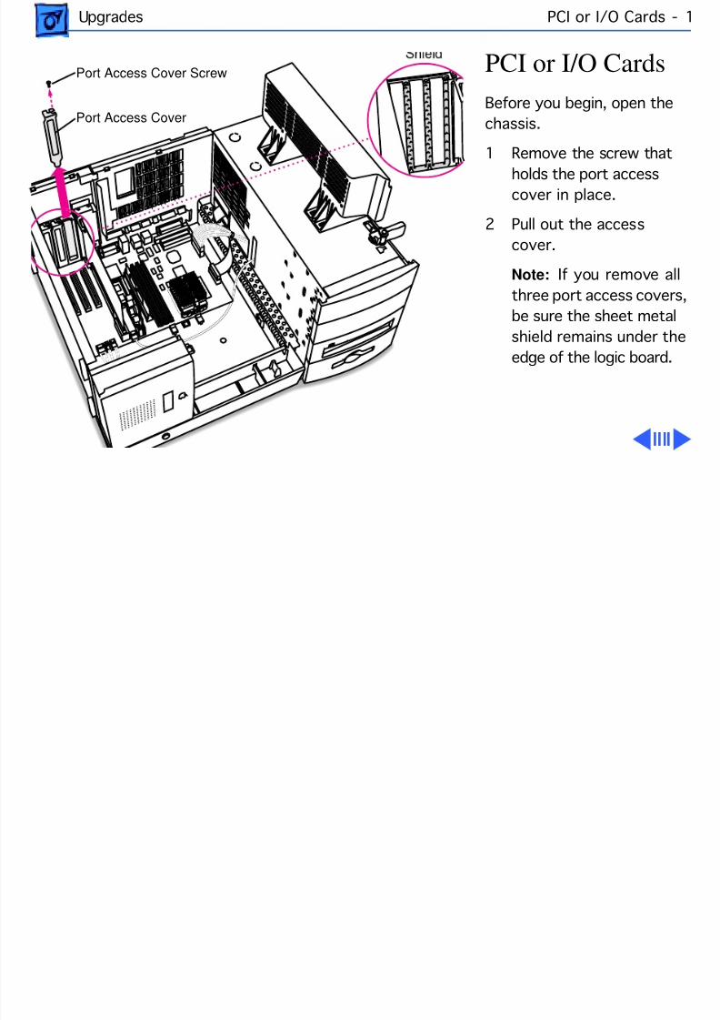
8/19/2019 Powermac Server g3 Minitower
http://slidepdf.com/reader/full/powermac-server-g3-minitower 222/292
Upgrades PCI or I/O Cards -
PCI or I/O CardsBefore you begin, open thechassis.
1 Remove the screw thatholds the port accesscover in place.
2 Pull out the accesscover.
Note: If you remove athree port access covers,be sure the sheet metal
shield remains under theedge of the logic board.
Port Access Cover
Port Access Cover Screw
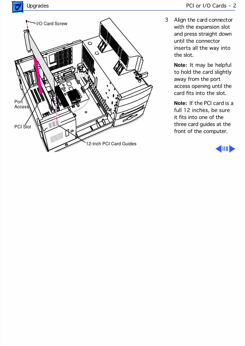
8/19/2019 Powermac Server g3 Minitower
http://slidepdf.com/reader/full/powermac-server-g3-minitower 223/292
Upgrades PCI or I/O Cards -
3 Align the card connectorwith the expansion slotand press straight downuntil the connectorinserts all the way into
the slot.Note: It may be helpfuto hold the card slightlyaway from the portaccess opening until thecard fits into the slot.
Note: If the PCI card isfull 12 inches, be sureit fits into one of thethree card guides at thefront of the computer.
PortAccess
PCI Slot
12-Inch PCI Card Guides
I/O Card Screw
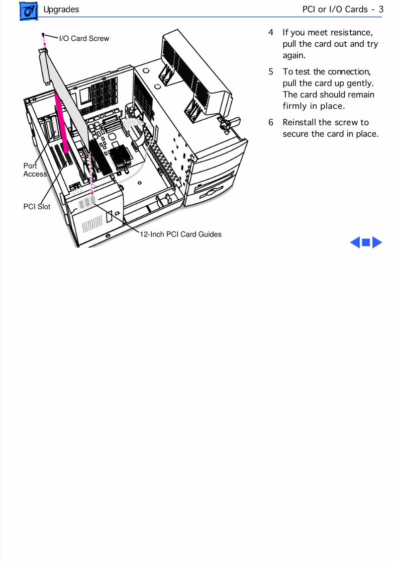
8/19/2019 Powermac Server g3 Minitower
http://slidepdf.com/reader/full/powermac-server-g3-minitower 224/292
Upgrades PCI or I/O Cards -
4 If you meet resistance,pull the card out and tryagain.
5 To test the connection,pull the card up gently.
The card should remainfirmly in place.
6 Reinstall the screw tosecure the card in place.
PortAccess
PCI Slot
12-Inch PCI Card Guides
I/O Card Screw
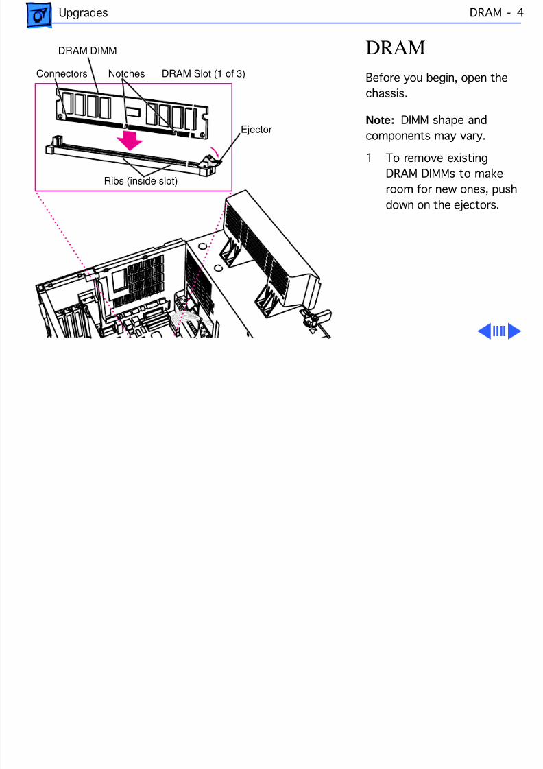
8/19/2019 Powermac Server g3 Minitower
http://slidepdf.com/reader/full/powermac-server-g3-minitower 225/292
Upgrades DRAM
DRAMBefore you begin, open thechassis.
Note: DIMM shape andcomponents may vary.
1 To remove existingDRAM DIMMs to makroom for new ones, pushdown on the ejectors.
DRAM DIMM
Ejector
Connectors Notches DRAM Slot (1 of 3)
Ribs (inside slot)
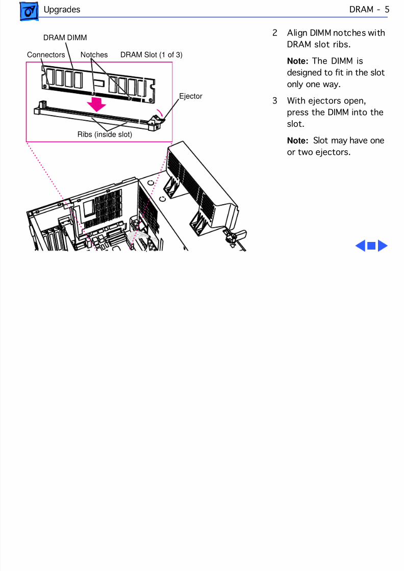
8/19/2019 Powermac Server g3 Minitower
http://slidepdf.com/reader/full/powermac-server-g3-minitower 226/292
Upgrades DRAM
2 Align DIMM notches wiDRAM slot ribs.
Note: The DIMM isdesigned to fit in the slotonly one way.
3 With ejectors open,press the DIMM into thslot.
Note: Slot may have onor two ejectors.
DRAM DIMM
Ejector
Connectors Notches DRAM Slot (1 of 3)
Ribs (inside slot)
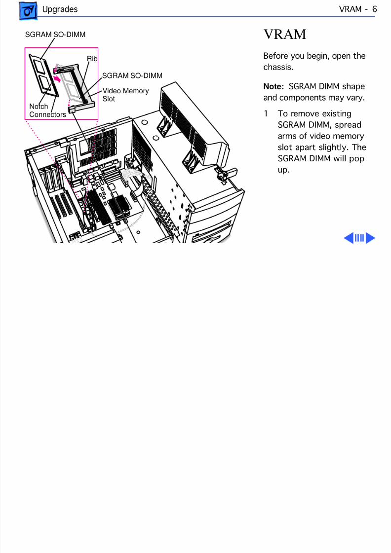
8/19/2019 Powermac Server g3 Minitower
http://slidepdf.com/reader/full/powermac-server-g3-minitower 227/292
Upgrades VRAM
VRAMBefore you begin, open thechassis.
Note: SGRAM DIMM shaand components may vary.
1 To remove existingSGRAM DIMM, spreaarms of video memoryslot apart slightly. TheSGRAM DIMM will pup.
SGRAM SO-DIMM
SGRAM SO-DIMM
Video MemorySlotNotch
Rib
Connectors
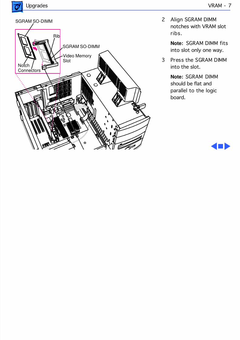
8/19/2019 Powermac Server g3 Minitower
http://slidepdf.com/reader/full/powermac-server-g3-minitower 228/292
Upgrades VRAM
2 Align SGRAM DIMMnotches with VRAM slotribs.
Note: SGRAM DIMMinto slot only one way.
3 Press the SGRAM DIMinto the slot.
Note: SGRAM DIMMshould be flat andparallel to the logicboard.
SGRAM SO-DIMM
SGRAM SO-DIMM
Video MemorySlotNotch
Rib
Connectors

8/19/2019 Powermac Server g3 Minitower
http://slidepdf.com/reader/full/powermac-server-g3-minitower 229/292
Upgrades Modem Card -
Modem CardBefore you begin, do thefollowing:• Remove the side access
panel• Open the chassis• Remove the I/O Card
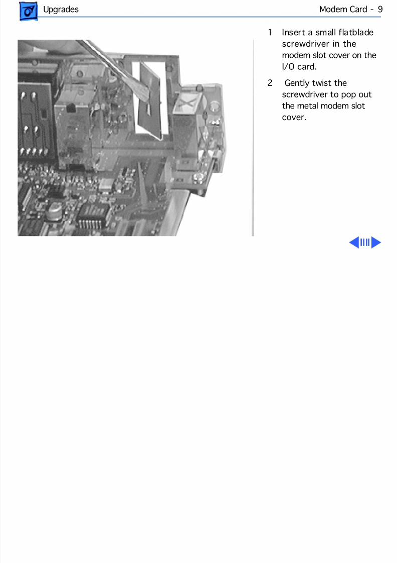
8/19/2019 Powermac Server g3 Minitower
http://slidepdf.com/reader/full/powermac-server-g3-minitower 230/292
Upgrades Modem Card -
1 Insert a small flatbladescrewdriver in themodem slot cover on theI/O card.
2 Gently twist the
screwdriver to pop outthe metal modem slotcover.
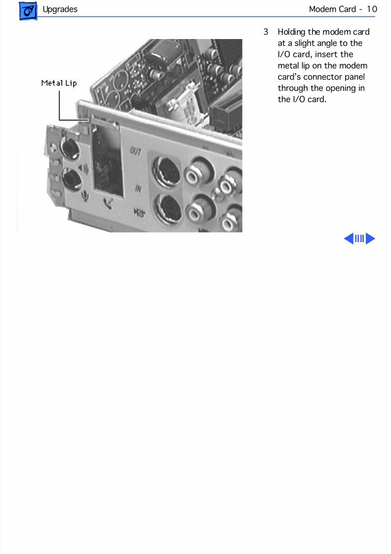
8/19/2019 Powermac Server g3 Minitower
http://slidepdf.com/reader/full/powermac-server-g3-minitower 231/292
Upgrades Modem Card - 1
3 Holding the modem cardat a slight angle to theI/O card, insert themetal lip on the modemcard’s connector panel
through the opening inthe I/O card.
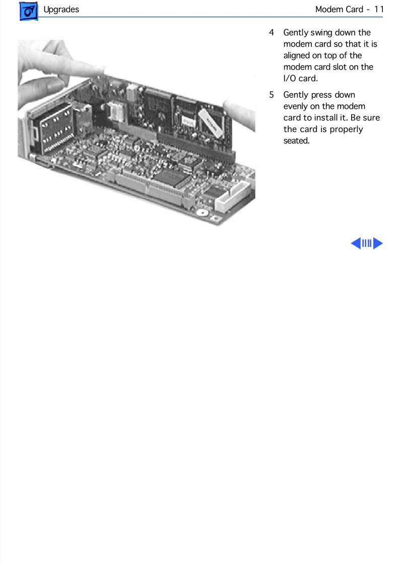
8/19/2019 Powermac Server g3 Minitower
http://slidepdf.com/reader/full/powermac-server-g3-minitower 232/292
Upgrades Modem Card - 1
4 Gently swing down themodem card so that it isaligned on top of themodem card slot on theI/O card.
5 Gently press downevenly on the modemcard to install it. Be surethe card is properlyseated.
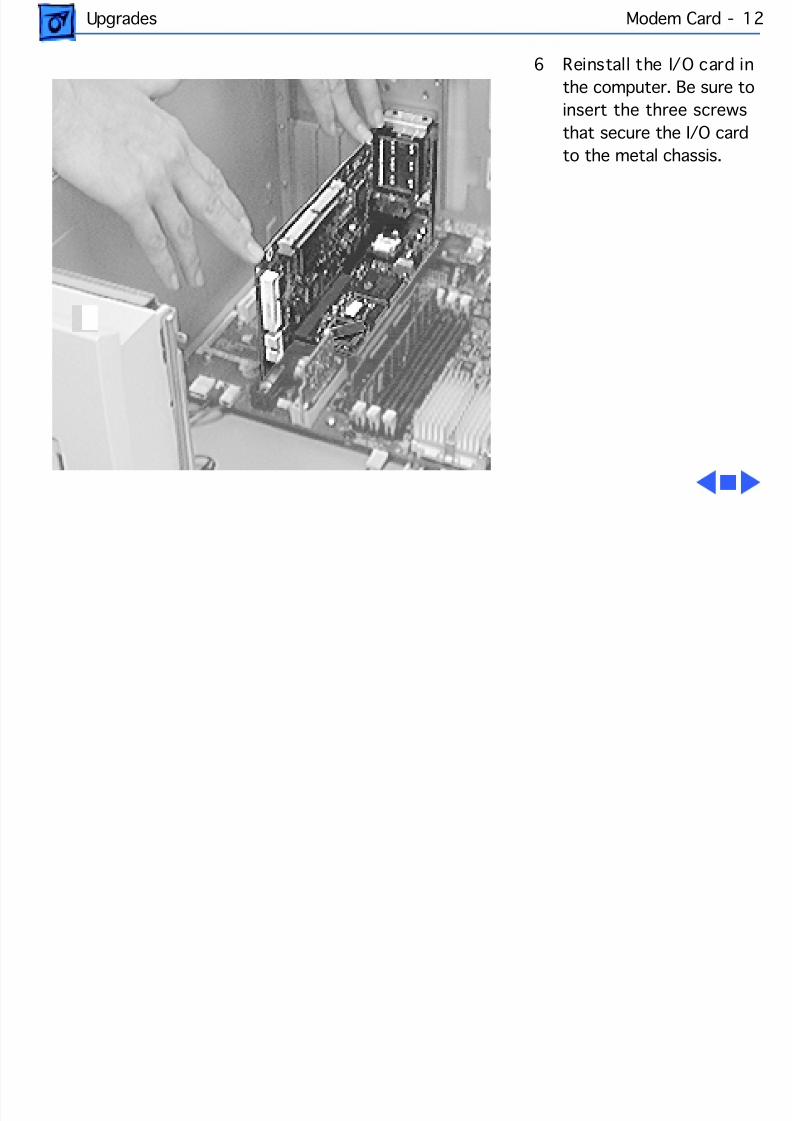
8/19/2019 Powermac Server g3 Minitower
http://slidepdf.com/reader/full/powermac-server-g3-minitower 233/292
Upgrades Modem Card - 1
6 Reinstall the I/O card inthe computer. Be sure toinsert the three screwsthat secure the I/O cardto the metal chassis.
8/19/2019 Powermac Server g3 Minitower
http://slidepdf.com/reader/full/powermac-server-g3-minitower 234/292
Service SourcK
TroubleshootingPower Macintosh/Server G3
Minitowe

8/19/2019 Powermac Server g3 Minitower
http://slidepdf.com/reader/full/powermac-server-g3-minitower 235/292
Troubleshooting General/ - 1
GeneralThe Symptom Charts included in this chapter will help youdiagnose specific symptoms related to your product. Because curesare listed on the charts in the order of most likely solution, try
the cures in the order presented. Verify whether or not theproduct continues to exhibit the symptom. If the symptompersists, try the next cure. (Note: If you have replaced a module,reinstall the original module before you proceed to the next cure.)
For additional assistance, contact Apple Technical Support.
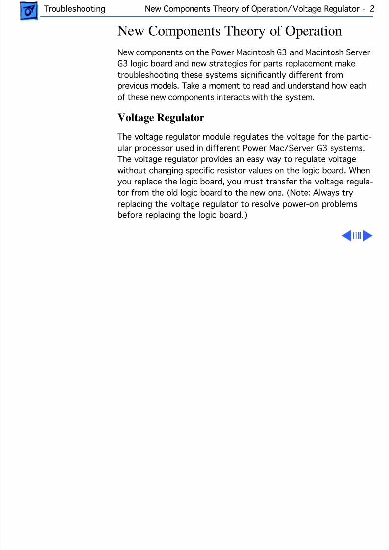
8/19/2019 Powermac Server g3 Minitower
http://slidepdf.com/reader/full/powermac-server-g3-minitower 236/292
Troubleshooting New Components Theory of Operation/Voltage Regulator - 2
New Components Theory of OperationNew components on the Power Macintosh G3 and Macintosh ServerG3 logic board and new strategies for parts replacement maketroubleshooting these systems significantly different fromprevious models. Take a moment to read and understand how eachof these new components interacts with the system.
Voltage Regulator
The voltage regulator module regulates the voltage for the partic-ular processor used in different Power Mac/Server G3 systems.The voltage regulator provides an easy way to regulate voltagewithout changing specific resistor values on the logic board. When
you replace the logic board, you must transfer the voltage regula-tor from the old logic board to the new one. (Note: Always tryreplacing the voltage regulator to resolve power-on problemsbefore replacing the logic board.)
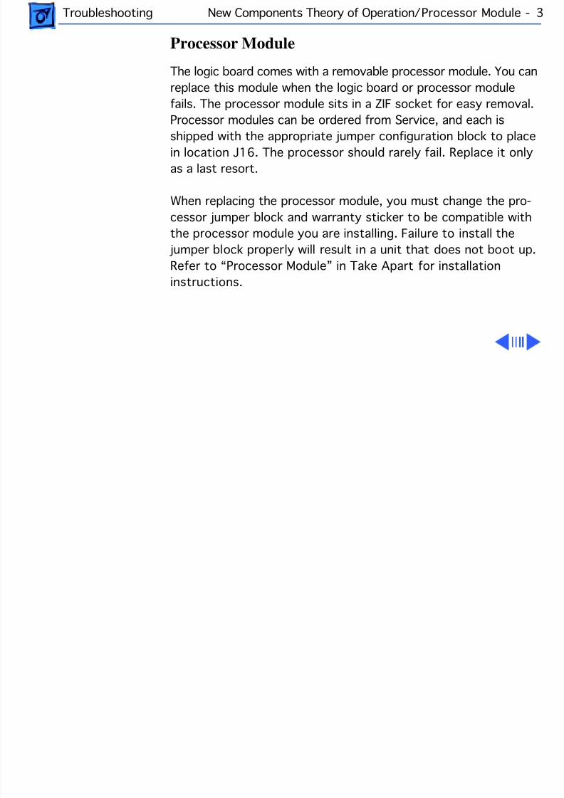
8/19/2019 Powermac Server g3 Minitower
http://slidepdf.com/reader/full/powermac-server-g3-minitower 237/292
Troubleshooting New Components Theory of Operation/Processor Module - 3
Processor Module
The logic board comes with a removable processor module. You canreplace this module when the logic board or processor modulefails. The processor module sits in a ZIF socket for easy removal.Processor modules can be ordered from Service, and each isshipped with the appropriate jumper configuration block to placein location J16. The processor should rarely fail. Replace it onlyas a last resort.
When replacing the processor module, you must change the pro-cessor jumper block and warranty sticker to be compatible withthe processor module you are installing. Failure to install the
jumper block properly will result in a unit that does not boot up.
Refer to “Processor Module” in Take Apart for installationinstructions.
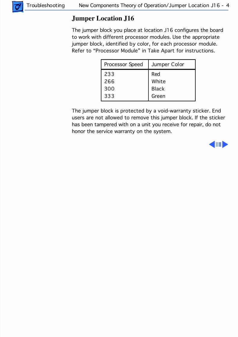
8/19/2019 Powermac Server g3 Minitower
http://slidepdf.com/reader/full/powermac-server-g3-minitower 238/292
Troubleshooting New Components Theory of Operation/Jumper Location J16 - 4
Jumper Location J16
The jumper block you place at location J16 configures the boardto work with different processor modules. Use the appropriate
jumper block, identified by color, for each processor module.Refer to “Processor Module” in Take Apart for instructions.
The jumper block is protected by a void-warranty sticker. Endusers are not allowed to remove this jumper block. If the stickerhas been tampered with on a unit you receive for repair, do nothonor the service warranty on the system.
Processor Speed Jumper Color
233266300333
RedWhiteBlackGreen
8/19/2019 Powermac Server g3 Minitower
http://slidepdf.com/reader/full/powermac-server-g3-minitower 239/292
Troubleshooting New Components Theory of Operation/Jumper Location J28 - 5
Jumper Location J28
Jumper location J28 controls which power supply the logic boardcan accommodate. When you receive a Power Macintosh G3/Mac-intosh Server G3 logic board from Service, you need to place the
jumper in the proper location. The power supply used in thePower Macintosh G3 Desktop computer is different from thepower supply used in the Power Macintosh G3 Minitower andMacintosh Server G3 computers.
If the logic board is installed in the Minitower/Server chassis,the power supply jumper must cover the pins marked “PS”. Ifthe logic board is installed in the Desktop chassis, this jumpermust cover the pins marked “Mac”. (Replacement logic boards
should come preset for the Desktop model.) When replacing thelogic board, be sure to check the power supply jumper setting. Ifthis jumper is missing or set incorrectly for the computer model,the computer will not boot up

8/19/2019 Powermac Server g3 Minitower
http://slidepdf.com/reader/full/powermac-server-g3-minitower 240/292
Troubleshooting New Components Theory of Operation/I/O Cards - 6
I/O Cards
Power Macintosh G3/Macintosh Server G3 computers require anI/O card that moves video and/or audio from the main logic board.These cards are placed in the PERCH connector on the main logicboard. If the card is not seated correctly, different symptomsappear. Look in the Symptom Charts for details on troubleshootingthese cards.
Note: the computer will boot up without the I/O card installed, butthey will not operate properly.
8/19/2019 Powermac Server g3 Minitower
http://slidepdf.com/reader/full/powermac-server-g3-minitower 241/292
Troubleshooting New Components Theory of Operation/HFS+ Formatted Drives -
HFS+ Formatted Drives
Some Power Macintosh G3 Minitower computers ship with harddrives that are formatted with HFS and some later models shipwith hard drives that are formatted with HFS+ (also referred toas Mac OS Extended format). (Note: the hard drives in allMacintosh Server G3 computers are formatted with HFS+.)Before you try to repair a customer’s hard drive, it is imperativethat you determine how the drive has been formatted.
Norton Utilities version 3.5 is not compatible with HFS+ (or MacOS Extended format), and in fact, can destroy data on the harddrive. Norton Utilities version 3.5.3 or 3.5.2 will not attempt torepair a drive formatted with Mac OS Extended format and
versions 3.5.1 and earlier cannot recognize that a hard drive is inMac OS Extended format and can result in hard drive corruptionand loss of all data on the drive.
8/19/2019 Powermac Server g3 Minitower
http://slidepdf.com/reader/full/powermac-server-g3-minitower 242/292
Troubleshooting New Components Theory of Operation/HFS+ Formatted Drives -
Note: When diagnosing hard drive problems, it is important toverify whether or not the customer may have used the wrong diskrepair software for their drive before assuming that the problemis hardware related.
If you experience problems with a hard drive that has been
formatted with HFS+, Apple Computer recommends using theversion of Disk First Aid included on the system software CD thatshipped with the unit. (See the Symantec Web site at http://www.symantec.com/nu/num-hfs.html for more information onNorton Utilities and Mac OS Extended format.)
Some other disk utility and disk locking programs areincompatible with Mac OS Extended format. Before you attempt to
use a disk utility or disk locking program, make sure the versionyou have is compatible with Mac OS Extended format. Check thedocumentation that came with the program or contact themanufacturer or the vendor that supplied the program.

8/19/2019 Powermac Server g3 Minitower
http://slidepdf.com/reader/full/powermac-server-g3-minitower 243/292
Troubleshooting New Components Theory of Operation/HFS+ Formatted Drives -
Use the Get Info command in system 8.1 to determine how a harddrive has been formatted. Drives formatted with HFS will appearas “Mac OS Standard”, while drives formatted with HFS+ willappear as “Mac OS Extended.”
For more information on HFS+ formatting of hard drives, refer tothe Technical Info Library, article # 30344.

8/19/2019 Powermac Server g3 Minitower
http://slidepdf.com/reader/full/powermac-server-g3-minitower 244/292
Troubleshooting Cleaning Procedure for Card Connectors/HFS+ Formatted Drives
Cleaning Procedure for Card ConnectorsIt is possible for residue to build up on the gold edge connectorpins on some PCI cards, which could cause a variety of symptoms.
If you are having problems with a PCI card, inspect the connectorpins with a magnifying glass. If you find residue, use a pencileraser to gently clean the pins.
8/19/2019 Powermac Server g3 Minitower
http://slidepdf.com/reader/full/powermac-server-g3-minitower 245/292
Troubleshooting Power Supply Verification/Verification Procedure - 11
Power Supply VerificationThe Power Macintosh G3 logic board requires a “trickle” powerof +5V to start up. If the system fails to start up, follow theprocedure outlined below to determine whether the problem isrelated to the power supply.
Note: To verify the power supply, you need a volt meter.
Verification Procedure
Follow the procedures in the Take Apart chapter to access thepower supply.
Important: For this verification procedure when connecting thevolt meter leads to specific pins, ensure the power supply cableremains securely plugged into the power supply 20-pin connec-tor on the logic board.
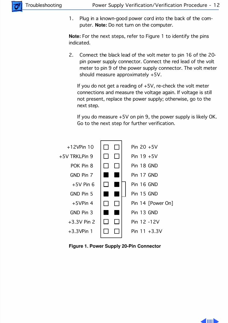
8/19/2019 Powermac Server g3 Minitower
http://slidepdf.com/reader/full/powermac-server-g3-minitower 246/292
Troubleshooting Power Supply Verification/Verification Procedure - 12
1. Plug in a known-good power cord into the back of the com-puter. Note: Do not turn on the computer.
Note: For the next steps, refer to Figure 1 to identify the pinsindicated.
2. Connect the black lead of the volt meter to pin 16 of the 20-pin power supply connector. Connect the red lead of the voltmeter to pin 9 of the power supply connector. The volt metershould measure approximately +5V.
If you do not get a reading of +5V, re-check the volt meterconnections and measure the voltage again. If voltage is stillnot present, replace the power supply; otherwise, go to the
next step.If you do measure +5V on pin 9, the power supply is likely OK.Go to the next step for further verification.
Figure 1. Power Supply 20-Pin Connector
Pin 20 +5V
Pin 19 +5V
Pin 18 GND
Pin 17 GND
Pin 16 GND
Pin 15 GND
Pin 14 [Power On]
Pin 13 GND
Pin 12 -12V
Pin 11 +3.3V
+12V Pin 10
+5V TRKL Pin 9
POK Pin 8
GND Pin 7
+5V Pin 6
GND Pin 5
+5V Pin 4
GND Pin 3
+3.3V Pin 2
+3.3V Pin 1
8/19/2019 Powermac Server g3 Minitower
http://slidepdf.com/reader/full/powermac-server-g3-minitower 247/292
Troubleshooting Power Supply Verification/Verification Procedure - 13
3. Start up the computer by pressing the power button on thefront of the computer. Note: Verify that the power cable isplugged into connector J30.
If the computer starts up normally, the power supply is OK. Ifthe computer does not start up, go to the next step.
4. Check to see if the power supply fan is spinning.
If the power supply fan is not spinning, verify that the jumper at connector J28 is installed in the correct location(on the Minitower, the correct location is PS/2 Supply; on theDesktop, the correct location is MAC Supply); otherwise, go tothe next step.
5. Connect the black lead of the volt meter to pin 16 of the powersupply connector. Connect the red lead of the volt meter to pin1 of the power supply connector. The volt meter should mea-sure approximately +3.3V.
8/19/2019 Powermac Server g3 Minitower
http://slidepdf.com/reader/full/powermac-server-g3-minitower 248/292
Troubleshooting Power Supply Verification/Verification Procedure - 14
If you do not get a reading of +3.3V, re-check the volt meterconnections and measure the voltage again. If voltage is stillnot present, replace the power supply; otherwise, go to thenext step.
6. Connect the black lead of the volt meter to pin 16 of the power
supply connector. Connect the red lead of the volt meter to pin4 of the power supply connector. The volt meter should mea-sure approximately +5V.
If you do not get a reading of +5V, re-check the volt meterconnections and measure the voltage again. If voltage is stillnot present, replace the power supply; otherwise, go to thenext step.
7. Measure the voltage of pin 10 on the power supply connector.The voltage should measure approximately +12V.
If you do not get a reading of +12V, re-check the volt meter

8/19/2019 Powermac Server g3 Minitower
http://slidepdf.com/reader/full/powermac-server-g3-minitower 249/292
8/19/2019 Powermac Server g3 Minitower
http://slidepdf.com/reader/full/powermac-server-g3-minitower 250/292
Troubleshooting Symptom Charts/System - 16
Symptom Charts
System
n on power supply
running, but noartup chime, screenblack, drive notcessed at startup,d no LED on front ofstem
1 Verify power supply voltage switch is set correctly for your
region (see “Voltage Switch” in Basics chapter for moreinformation).2 Check jumper block J28. Be sure setting is correct for type
of power supply installed (see “Logic Board” in Take Apartchapter for more information).
3 Check jumper block configuration at J16. Make sure jumperblock is correct color for processor type installed (see“Processor Module” in Take Apart chapter for moreinformation) and that it is installed in the correct direction.
4 Reseat voltage regulator.5 Reseat processor module. Make sure locking arm is in down
position.
8/19/2019 Powermac Server g3 Minitower
http://slidepdf.com/reader/full/powermac-server-g3-minitower 251/292
Troubleshooting Symptom Charts/System - 17
6 Reseat ROM DIMM.7 Replace voltage regulator.8 Replace logic board.9 Replace processor module.
n is running, LED is, drive is accessedstartup, but no
artup chime andreen is black
Reseat ROM DIMM.
o apparent power,n isn’t running, noED
1 Verify power cord is attached securely at both ends.2 Verify that the power outlet is good.3 Verify ADB cable is good and connected properly.4 Check internal power cables and verify they are attached
securely at both ends.5 Check jumper block J28. Make sure setting is correct for
type of power supply installed (see “Logic Board” in Take

8/19/2019 Powermac Server g3 Minitower
http://slidepdf.com/reader/full/powermac-server-g3-minitower 252/292
Troubleshooting Symptom Charts/System - 18
Apart chapter for more information).6 Reset Cuda chip. (Refer to “The Cuda Chip” in Basics chapter
for instructions.)7 Reset logic board. (Refer to “Resetting the Logic Board” in
Basics chapter for instructions.)8 Replace power cord.9 Reseat voltage regulator.10 Check the power supply by following the procedures in
“Power Supply Verification” outlined earlier in thischapter.
11 Replace logic board.
8/19/2019 Powermac Server g3 Minitower
http://slidepdf.com/reader/full/powermac-server-g3-minitower 253/292
Troubleshooting Symptom Charts/System - 19
omputer begins tower up, the fan andrd drive areinning, the power
ED is lit, but thereno video and theot chime is followedsound of breaking
ass
1 Reseat ROM DIMM.2 Reseat DRAM DIMMs. (Note: the computer does not ship with
any on-board memory. You must have a DRAM DIMM installedfor the computer to boot properly.)
3 Test for a bad DRAM DIMM by removing the DIMMs one at atime (replacing each one afterwards). Replace any faultyDRAM DIMMs.
4 Verify external SCSI cabling is secure.5 Verify external SCSI devices are good.
icking, chirping,umping, or rubbing
1 Remove all PCI cards and test unit. If problem does not occurwith cards removed, begin replacing cards one at a time todetermine which card is causing problem. Replace problemcard with known-good card.
2 Remove hard drive. If problem no longer occurs, replace harddrive with a known-good drive.
3 Replace power supply.4 Replace processor module.
8/19/2019 Powermac Server g3 Minitower
http://slidepdf.com/reader/full/powermac-server-g3-minitower 254/292
Troubleshooting Symptom Charts/System - 20
5 Replace logic board.6 Replace floppy drive cable.7 Replace floppy drive.8 Replace I/O card.
stem shuts downtermittently
1 Make sure air vents are clear. Thermal protection circuitrymay shut down system. After 30 to 40 minutes, systemshould be OK.
2 Make sure power cord is plugged in firmly.3 Replace power cord.4 Check battery.5 Reset Cuda chip. (Refer to “The Cuda Chip” in Basics chapter
for instructions.)6 Reset logic board. (Refer to “Resetting the Logic Board” in
Basics chapter for instructions.)7 Replace power supply.8 Replace logic board.9 Replace processor module.
8/19/2019 Powermac Server g3 Minitower
http://slidepdf.com/reader/full/powermac-server-g3-minitower 255/292
Troubleshooting Symptom Charts/System - 21
stemtermittentlyashes or hangs
1 Verify system software is version 8.0 or later with enabler770 for G3 Minitower, or version 8.1 or later withappropriate software extensions for G3 Server.
2 Verify software is known-good. Do a clean install of systemsoftware.
3 Verify software is Power Macintosh compatible (contactdeveloper). Also, try booting with extensions off to determineif there are system init problems.
4 Clear parameter RAM. Hold down Command-Option-P-Rduring startup but before "Welcome to Macintosh" appears.
5 Remove all SDRAM DIMMs and try replacing them one at atime to test. Replace any bad DIMMs.
6 Replace logic board.7 Replace processor module.

8/19/2019 Powermac Server g3 Minitower
http://slidepdf.com/reader/full/powermac-server-g3-minitower 256/292
Troubleshooting Symptom Charts/System - 22
uring startup,llowing message issplayed, "Thisartup disk will notork on this
acintosh model...."
1 Verify startup disk is good.2 Verify system software is version 8.0 or later with enabler
770 for G3 Minitower, or version 8.1 or later withappropriate software extensions for G3 Server.
3 Do a clean install of system software.

8/19/2019 Powermac Server g3 Minitower
http://slidepdf.com/reader/full/powermac-server-g3-minitower 257/292
Troubleshooting Symptom Charts/Error Chords - 23
Error Chords
ne-part error chordound of breakingass) sounds during
artup sequence
1 Disconnect IDE data cable from hard drive and reboot system.If startup sequence is normal, initialize hard drive. Test unitagain with IDE data cable connected. If error chord still
sounds, replace hard drive.2 Disconnect floppy drive cable from floppy drive and rebootsystem. If startup sequence is normal, replace floppy drive.
3 Reseat processor module.4 Replace logic board.5 Replace processor module.
8/19/2019 Powermac Server g3 Minitower
http://slidepdf.com/reader/full/powermac-server-g3-minitower 258/292
Troubleshooting Symptom Charts/Video - 24
Video
reen is black, butot tone is present,ive operates, fan isnning, and LED is
1 Adjust brightness on monitor.2 Clear parameter RAM. Hold down Command-Option-P-R
during startup but before "Welcome to Macintosh" appears.3 Reset Cuda chip. (Refer to “The Cuda Chip” in Basics chapter
for instructions.)4 Reset logic board. (Refer to “Resetting the Logic Board” in
Basics chapter for instructions.)5 Replace monitor cable.6 Remove all SDRAM DIMMs and try replacing them one at a
time to test. Replace any bad DIMMs.7 Test with known-good monitor. Replace monitor if necessary.
Refer to appropriate monitor manual to troubleshootdefective monitor.
8 Replace logic board.9 Replace processor module.
8/19/2019 Powermac Server g3 Minitower
http://slidepdf.com/reader/full/powermac-server-g3-minitower 259/292
Troubleshooting Symptom Charts/Video - 25
reen is black, noot tone and drivees not operate, butn is running andED is lit
1 Reset Cuda chip. (Refer to “The Cuda Chip” in Basics chapterfor instructions.)
2 Reset logic board. (Refer to “Resetting the Logic Board” inBasics chapter for instructions.)
3 Remove all SDRAM DIMMs and try replacing them one at atime to test. Replace any bad DIMMs.
4 Replace logic board.5 Replace power supply.6 Replace processor module.
oot tone is presentd screen lights up,t nothing issplayed on screen
1 Reset Cuda chip. (Refer to “The Cuda Chip” in Basics chapterfor instructions.)
2 Reset logic board. (Refer to “Resetting the Logic Board” inBasics chapter for instructions.)
3 Replace monitor cable.4 Test with known-good monitor. Replace monitor if necessary.
Refer to appropriate monitor manual to troubleshootdefective monitor.

8/19/2019 Powermac Server g3 Minitower
http://slidepdf.com/reader/full/powermac-server-g3-minitower 260/292
Troubleshooting Symptom Charts/Video - 26
5 Replace logic board.6 Replace processor module.
orizontal flickeringnes when viewing
pple Video Playplication with TVirroring on
Replace the Audio/Video card with a Version II Audio/Video card(p/n 661-2044).
V Mirroring isabled but no imageappearing on TV
Refer to TIL article 24816 for how to verify that video outputfrom Audio/Video card is working.
8/19/2019 Powermac Server g3 Minitower
http://slidepdf.com/reader/full/powermac-server-g3-minitower 261/292
Troubleshooting Symptom Charts/Floppy Drive - 27
Floppy Drive
ternal floppy drivees not operate
1 Replace floppy disk with known-good disk.2 Replace floppy drive cable.3 Replace floppy drive.4 Replace logic board.5 Replace processor module.
uring systemartup, disk ejects;splay shows iconth blinking "X"
1 Replace disk with known-good system disk.2 Replace floppy drive cable.3 Replace floppy drive.4 Replace logic board.5 Replace processor module.
sk does not eject 1 Switch off computer. Hold down mouse button while youswitch computer on.
2 Replace floppy drive cable.3 Replace floppy drive.
8/19/2019 Powermac Server g3 Minitower
http://slidepdf.com/reader/full/powermac-server-g3-minitower 262/292
Troubleshooting Symptom Charts/Floppy Drive - 28
4 Replace logic board.5 Replace processor module.
rive attempts toect disk, but doesn’t
1 Reseat floppy drive bezel and drive so bezel slot alignscorrectly with drive.
2 Replace floppy drive.
ternal floppy drivens continuously
1 Replace disk with known-good floppy disk.2 Replace floppy drive cable.3 Replace floppy drive.4 Replace logic board.5 Replace processor module.
S-DOS drive doest recognize a diskrmatted on a 1.4 MBive
To read and write files with either MS-DOS or 1.4 MB drive,format all disks with MS-DOS drive first.
8/19/2019 Powermac Server g3 Minitower
http://slidepdf.com/reader/full/powermac-server-g3-minitower 263/292
Troubleshooting Symptom Charts/Hard Drive - 29
Hard Drive
ngle internal hardive does noterate; drive doesn’tin
1 Replace hard drive power cable.2 Replace hard drive. If problem resolved, reinstall IDE device
driver and system software.3 Replace power supply.
o internal SCSIives operate
1 Verify there are no duplicate SCSI device addresses on asingle SCSI bus.
2 Disconnect external SCSI devices and check for propertermination. Only last device in SCSI chain should beterminated.
3 Check internal SCSI devices for proper termination.4 Replace internal SCSI data cable to which non-operational
devices are attached.5 Replace power supply.6 Replace logic board.7 Replace processor module.

8/19/2019 Powermac Server g3 Minitower
http://slidepdf.com/reader/full/powermac-server-g3-minitower 264/292
Troubleshooting Symptom Charts/Hard Drive - 30
orks with internalexternal SCSIvices but not withth
1 Verify there are no duplicate SCSI device addresses2 Replace terminator on external SCSI device.3 Verify that SCSI device at end of internal SCSI data cable is
only device terminated.4 Refer to appropriate manual to troubleshoot defective
external device.
8/19/2019 Powermac Server g3 Minitower
http://slidepdf.com/reader/full/powermac-server-g3-minitower 265/292
Troubleshooting Symptom Charts/Peripherals - 31
Peripherals
ursor does not move 1 Check mouse connection.2 Inspect inside of mouse for buildup of dirt or other
contaminants. Clean mouse if necessary. Note: The mousecontains a ball and several rollers that must remain clean. Ifeither the ball or rollers are dirty, the mouse might nottrack properly. Refer to Tech Info Library article 6491:“How To Clean A Mouse.”
3 If mouse was connected to keyboard, connect mouse tocomputer ADB port instead. If mouse works, replacekeyboard.
4 Replace ADB cable.5 If mouse does not work in any ADB port on computer, replace
mouse.6 Replace logic board.7 Replace processor module.
8/19/2019 Powermac Server g3 Minitower
http://slidepdf.com/reader/full/powermac-server-g3-minitower 266/292
Troubleshooting Symptom Charts/Peripherals - 32
ursor moves, butcking mouse buttons no effect
1 Boot from floppy or bootable CD.2 Replace mouse.3 Replace logic board.
ouble-click doesn’ten application,sk, or server
1 Remove duplicate system folders.2 Clear parameter RAM. Hold down Command-Option-P-R
during startup but before "Welcome to Macintosh" appears.3 If mouse was connected to keyboard, connect mouse to
computer ADB port instead. If mouse works, replacekeyboard.
4 If mouse does not work in any ADB port on computer, replacemouse.
5 Replace logic board. Retain customer's DIMMs.
o response to anyy on keyboard
1 Check keyboard connection to ADB port.2 Replace keyboard cable.3 Replace keyboard.4 Replace logic board.
8/19/2019 Powermac Server g3 Minitower
http://slidepdf.com/reader/full/powermac-server-g3-minitower 267/292
Troubleshooting Symptom Charts/Peripherals - 33
nown-good serialinter does not work
1 Verify you have correct version of system software.2 Verify that Chooser is set correctly.3 Reinstall correct printer drivers.4 Do clean install of system software.5 Replace printer interface cable.
6 Replace logic board. Retain customer's DIMMs.
nown-good networkinter does not print
1 Check network connections.2 Verify you have correct version of system software.3 Verify that Chooser is set correctly.4 Does printer show up in Chooser? If so, do clean install of
system software and/or network and printer software.5 Replace logic board. Retain customer's DIMMs.
olor StyleWriter00 printer doest respond
Upgrade to the Color StyleWriter 4500 driver, version 1.1 orlater. Refer to this URL online: http://www.apple.com/support/
8/19/2019 Powermac Server g3 Minitower
http://slidepdf.com/reader/full/powermac-server-g3-minitower 268/292
Troubleshooting Symptom Charts/CD-ROM Drive - 34
CD-ROM Drive
D-ROM drive doest work
1 Try using known-good compact disc.2 Replace CD-ROM drive mechanism.
acintosh does notsplay CD-ROM iconce CD is inserted inive
1 Try using known-good compact disc.2 Verify CD-ROM software is installed.3 Reinstall CD-ROM software. You may have to use an external
CD-ROM drive.4 Reseat CD-ROM data cable at logic board connector as well as
at CD-ROM connector.5 Replace CD-ROM drive mechanism.6 Replace CD-ROM data cable.
8/19/2019 Powermac Server g3 Minitower
http://slidepdf.com/reader/full/powermac-server-g3-minitower 269/292
Troubleshooting Symptom Charts/Miscellaneous - 35
Miscellaneous
o sound fromeaker
1 Disconnect any microphones or external speakers.2 Verify that volume setting in Control Panel is adequate and
mute is not checked.
3 Clear parameter RAM. Hold down Command-Option-P-Rduring startup but before "Welcome to Macintosh" appears.Verify speaker is plugged into logic board.
4 Plug headphones or external speakers into the external jack.If the external jack works, replace the internal speaker orlogic board. If the external jack doesn’t work, proceed to thenext step.
5 Replace I/O Audio card.
6 Replace speaker.7 Replace logic board.
hernet connectionops off line by itself
Install Ethernet driver 2.0.4 or later.
8/19/2019 Powermac Server g3 Minitower
http://slidepdf.com/reader/full/powermac-server-g3-minitower 270/292
Service SourcK
Exploded ViewPower Macintosh/Server G3
Minitowe
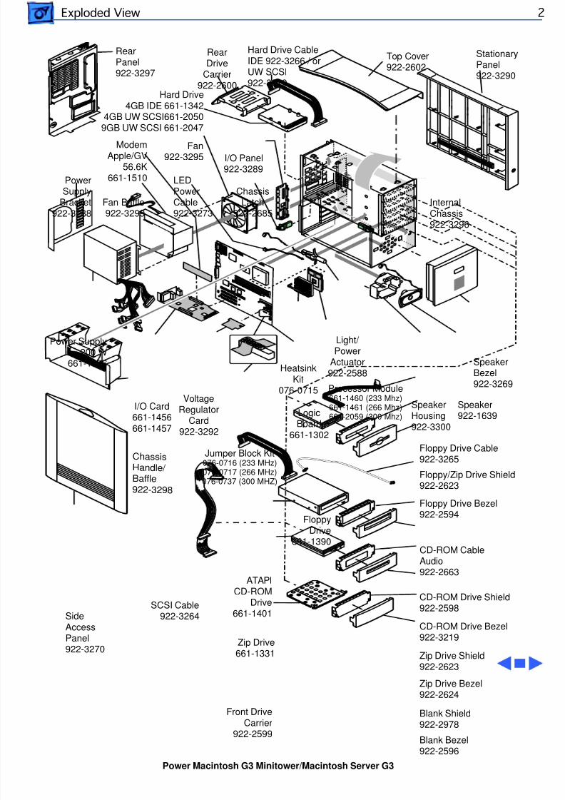
8/19/2019 Powermac Server g3 Minitower
http://slidepdf.com/reader/full/powermac-server-g3-minitower 271/292
Exploded View
Top Cover922-2602
Power Supply200 W
661-1496
PowerSupply
Bracket922-3288
Fan922-3295
ModemApple/GV
56.6K661-1510
SideAccessPanel922-3270
RearDrive
Carrier922-2600
Hard Drive4GB IDE 661-1342
4GB UW SCSI661-20509GB UW SCSI 661-2047
Hard Drive CableIDE 922-3266 / orUW SCSI922-3329
Floppy
Drive661-1390
Floppy/Zip Drive Shield922-2623
Floppy Drive Bezel922-2594
ATAPICD-ROM
Drive661-1401
CD-ROM CableAudio922-2663
CD-ROM Drive Shield922-2598
CD-ROM Drive Bezel922-3219Zip Drive
661-1331 Zip Drive Shield922-2623Zip Drive Bezel
Light/ Power
Actuator922-2588Heatsink
Kit076-0715
LogicBoard
661-1302
SpeakerBezel922-3269
I/O Panel 922-3289
I/O Card661-1456661-1457
ChassisLatch
922-2685
SpeakerHousing922-3300
Speaker922-1639
C h a ss is H a n d le / B a ffle92 2 -3 2 9 8
RearPanel922-3297
StationaryPanel922-3290
Fan Baffle922-3299
InternalChassis922-3296
VoltageRegulator
Card922-3292
Floppy Drive Cable922-3265
SCSI Cable922-3264
LEDPowerCable922-3273
Processor Module661-1460 (233 Mhz)661-1461 (266 Mhz)661-2059 (300 Mhz)
Jumper Block Kit076-0716 (233 MHz)076-0717 (266 MHz)076-0737 (300 MHZ)
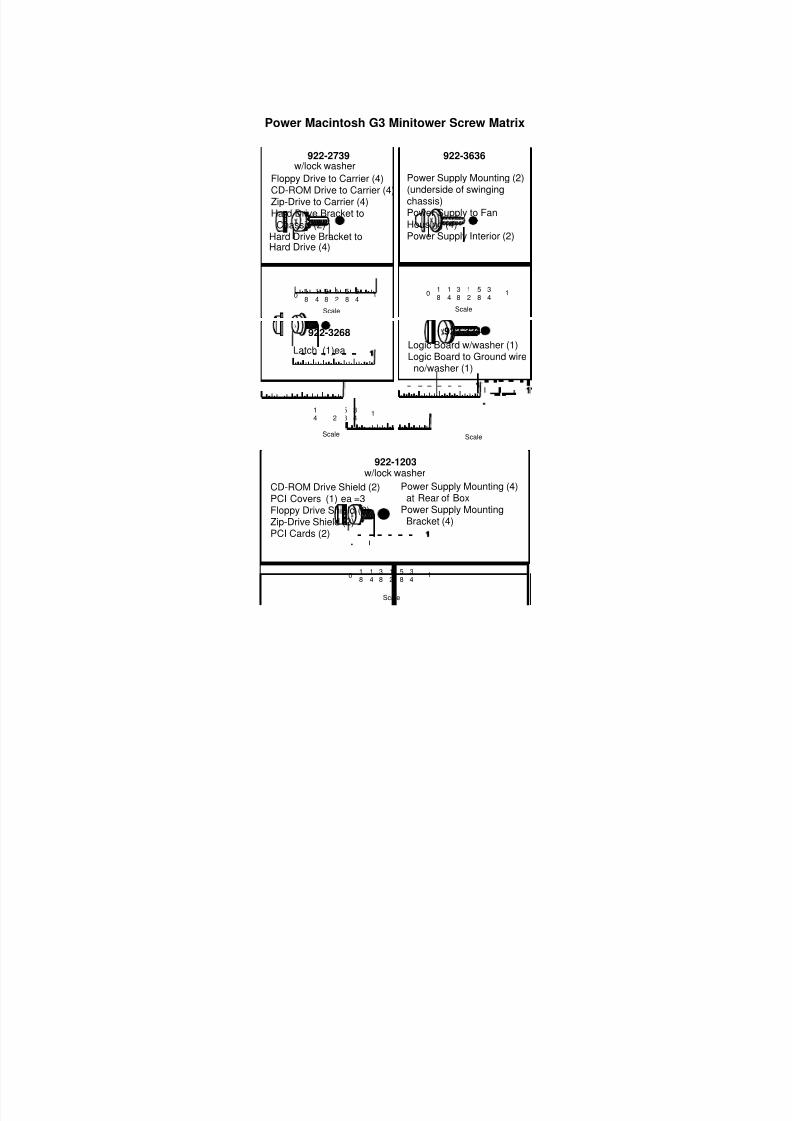
8/19/2019 Powermac Server g3 Minitower
http://slidepdf.com/reader/full/powermac-server-g3-minitower 272/292
0 118
38
58
12
34
14
Scale
0 118
38
58
12
34
14
Scale
0 118
38
58
12
34
14
Scale
0 118
38
58
12
34
14
0 118
38
58
12
34
14
Logic Board w/washer (1)Logic Board to Ground wire
no/washer (1)
Power Macintosh G3 Minitower Screw Matrix
CD-ROM Drive Shield (2)PCI Covers (1) ea =3Floppy Drive Shield (2)Zip-Drive Shield (2)PCI Cards (2)
Hard Drive Bracket toHard Drive (4)
Power Supply Mounting (2)(underside of swingingchassis)Power Supply to FanHousing (4)Power Supply Interior (2)
Power Supply Mounting (4) at Rear of BoxPower Supply Mounting
Bracket (4)
Latch (1)ea
922-3636
922-3240922-3268
922-1203
Scale
Scale
Floppy Drive to Carrier (4)CD-ROM Drive to Carrier (4)Zip-Drive to Carrier (4)Hard Drive Bracket to
Chassis (2)
w/lock washer
w/lock washer
922-2739
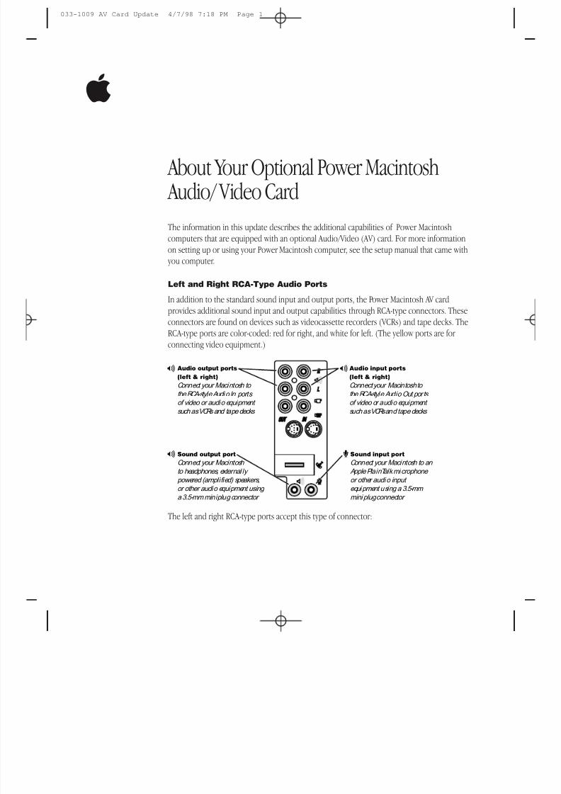
8/19/2019 Powermac Server g3 Minitower
http://slidepdf.com/reader/full/powermac-server-g3-minitower 273/292
About Your Optional Power Macintosh Audio/ Video Card
The information in this update describes the additional capabilities of Power Macintoshcomputers that are equipped with an optional Audio/Video (AV) card. For more informationon setting up or using your Power Macintosh computer, see the setup manual that came with
you computer.
Left and Right RCA-Type Audio Ports
In addition to the standard sound input and output ports, the Power Macintosh AV cardprovides additional sound input and output capabilities through RCA-type connectors. Theseconnectors are found on devices such as videocassette recorders (VCRs) and tape decks. TheRCA-type ports are color-coded: red for right, and white for left. (The yellow ports are for connecting video equipment.)
The left and right RCA-type ports accept this type of connector:
- Audio output ports(left & right)
Connect your Macintosh to
the RCA-style Audi o In ports of video or audio equipment such as VCRs and tape decks
Audio input ports(left & right)
Connect your Macintosh to
the RCA-style Audio Out por ts of video or audio equipment such as VCRs and tape decks
-
- Sound output port
Connect your Macintosh to headphones, external ly powered (amplified) speakers,or other audio equipment using a 3.5-mm miniplug connector
Sound input port
Connect your Macintosh to an Apple PlainTalk microphone or other audi o input equipment using a 3.5-mm mini plug connector
≈
033-1009 AV Card Update 4/7/98 7:18 PM Page 1
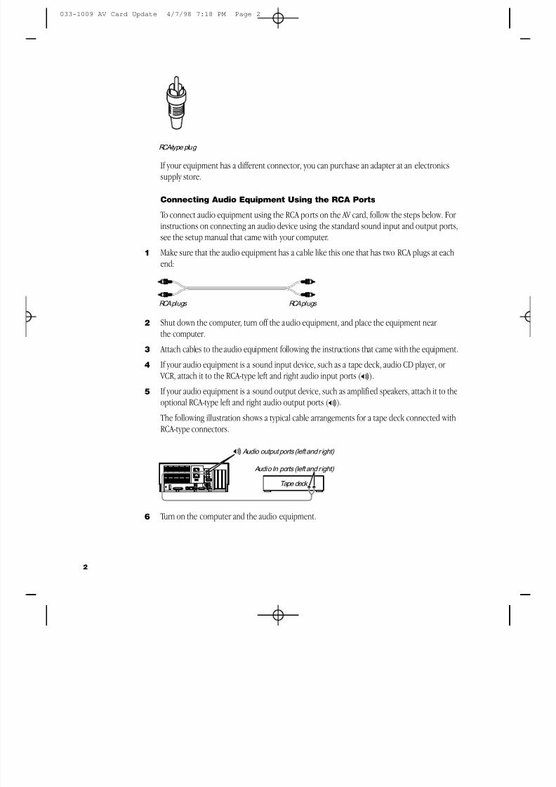
8/19/2019 Powermac Server g3 Minitower
http://slidepdf.com/reader/full/powermac-server-g3-minitower 274/292
If your equipment has a different connector, you can purchase an adapter at an electronicssupply store.
Connecting Audio Equipment Using the RCA Ports
To connect audio equipment using the RCA ports on the AV card, follow the steps below. For instructions on connecting an audio device using the standard sound input and output ports,see the setup manual that came with your computer.
1 Make sure that the audio equipment has a cable like this one that has two RCA plugs at eachend:
2 Shut down the computer, turn off the audio equipment, and place the equipment nearthe computer.
3 Attach cables to the audio equipment following the instructions that came with the equipment.
4 If your audio equipment is a sound input device, such as a tape deck, audio CD player, or VCR, attach it to the RCA-type left and right audio input ports ( - ).
5 If your audio equipment is a sound output device, such as amplified speakers, attach it to theoptional RCA-type left and right audio output ports ( - ).
The following illustration shows a typical cable arrangements for a tape deck connected withRCA-type connectors.
6 Turn on the computer and the audio equipment.
Audio output ports (left and r ight)
Audio In ports (left and r ight)
-
Tape deck
RCA plugs RCA plugs
RCA-type plug
2
033-1009 AV Card Update 4/7/98 7:18 PM Page 2
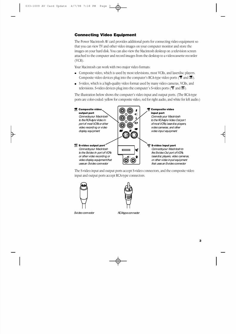
8/19/2019 Powermac Server g3 Minitower
http://slidepdf.com/reader/full/powermac-server-g3-minitower 275/292
Connecting Video Equipment
The Power Macintosh AV card provides additional ports for connecting video equipment sothat you can view TV and other video images on your computer monitor and store theimages on your hard disk. You can also view the Macintosh desktop on a television screen
attached to the computer and record images from the desktop to a videocassette recorder (VCR).
Your Macintosh can work with two major video formats:m Composite video, which is used by most televisions, most VCRs, and laserdisc players.
Composite video devices plug into the computer’s RCA-type video ports ( ˜ and ).m S-video, which is a high-quality video format used by many video cameras, VCRs, and
televisions. S-video devices plug into the computer’s S-video ports ( æ andÆ ).
The illustration below shows the computer’s video input and output ports. (The RCA-typeports are color-coded: yellow for composite video, red for right audio, and white for left audio.)
The S-video input and output ports accept S-video connectors, and the composite videoinput and output ports accept RCA-type connectors.
S-video connector RCA-type connector
ÂComposite videooutput port
Connects your Macintosh to the RCA-style Video In port of most VCRs or other video recordi ng or video display equipment
Composite videoinput port
Connects your Macintosh to the RCA-style Video Out por t of most VCRs, laserdisc players,video cameras, and other video input equipment
˜
Æ S-video output port
Connects your Macintosh to the S-video In port of VCRs or other video recording or video display equipment that uses an S-video connector
S-video input port
Connects your Macintosh to the S-video Out port of VCRs,laserdisc players, video cameras,or other video input equipment that uses an S-video connector
æ
3
033-1009 AV Card Update 4/7/98 7:18 PM Page 3
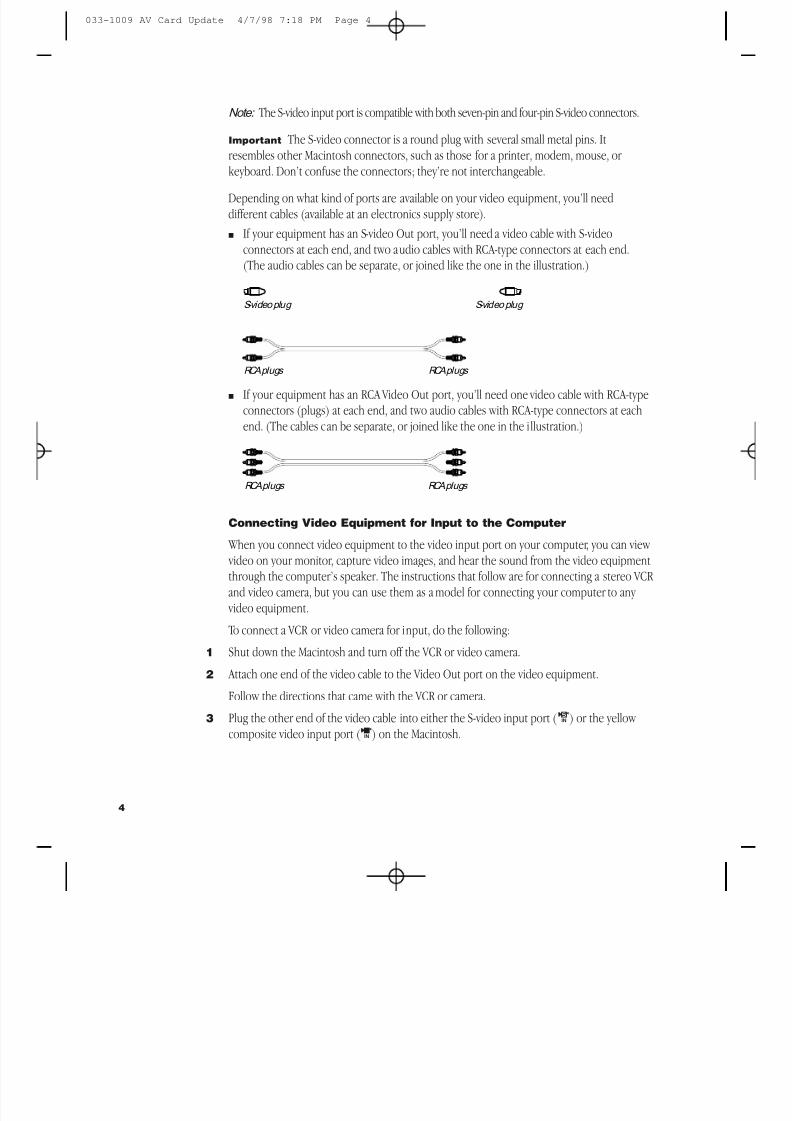
8/19/2019 Powermac Server g3 Minitower
http://slidepdf.com/reader/full/powermac-server-g3-minitower 276/292
Note: The S-video input port is compatible with both seven-pin and four-pin S-video connectors.
Important The S-video connector is a round plug with several small metal pins. Itresembles other Macintosh connectors, such as those for a printer, modem, mouse, or keyboard. Don’t confuse the connectors; they’re not interchangeable.
Depending on what kind of ports are available on your video equipment, you’ll needdifferent cables (available at an electronics supply store).m If your equipment has an S-video Out port, you’ll need a video cable with S-video
connectors at each end, and two audio cables with RCA-type connectors at each end.(The audio cables can be separate, or joined like the one in the illustration.)
m If your equipment has an RCA Video Out port, you’ll need one video cable with RCA-typeconnectors (plugs) at each end, and two audio cables with RCA-type connectors at eachend. (The cables can be separate, or joined like the one in the illustration.)
Connecting Video Equipment for Input to the Computer
When you connect video equipment to the video input port on your computer, you can view
video on your monitor, capture video images, and hear the sound from the video equipmentthrough the computer’s speaker. The instructions that follow are for connecting a stereo VCR and video camera, but you can use them as a model for connecting your computer to any video equipment.
To connect a VCR or video camera for input, do the following:
1 Shut down the Macintosh and turn off the VCR or video camera.
2 Attach one end of the video cable to the Video Out port on the video equipment.
Follow the directions that came with the VCR or camera.
3 Plug the other end of the video cable into either the S-video input port ( æ ) or the yellow composite video input port ( ˜ ) on the Macintosh.
RCA plugs RCA plugs
RCA plugs RCA plugs
S-video plug S-video plug
4
033-1009 AV Card Update 4/7/98 7:18 PM Page 4
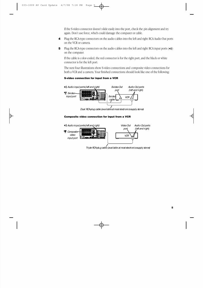
8/19/2019 Powermac Server g3 Minitower
http://slidepdf.com/reader/full/powermac-server-g3-minitower 277/292
If the S-video connector doesn’t slide easily into the port, check the pin alignment and try again. Don’t use force, which could damage the computer or cable.
4 Plug the RCA-type connectors on the audio cables into the left and right RCA Audio Out poron the VCR or camera.
5 Plug the RCA-type connectors on the audio cables into the left and right RCA input ports ( - )on the computer.
If the cable is color-coded, the red connector is for the right port, and the black or whiteconnector is for the left port.
The next four illustrations show S-video connections and composite video connections for both a VCR and a camera. Your finished connections should look like one of the following:
S-video connection for input from a VCR
Composite video connection for input from a VCR
Composite video
input port
Audio input ports (left and right)
Triple RCA-plug cable (avai lable at most electronics supply stores)
VCR ˜
- Video Out port
Audio Out ports (left and ri ght)
S-video input port
S-video Out port
S-video cable
VCR
æ
Audio input ports (left and right) Audio Out ports (left and ri ght)
Dual RCA-plug cable (available at most electroni cs supply stores)
-
5
033-1009 AV Card Update 4/7/98 7:18 PM Page 5
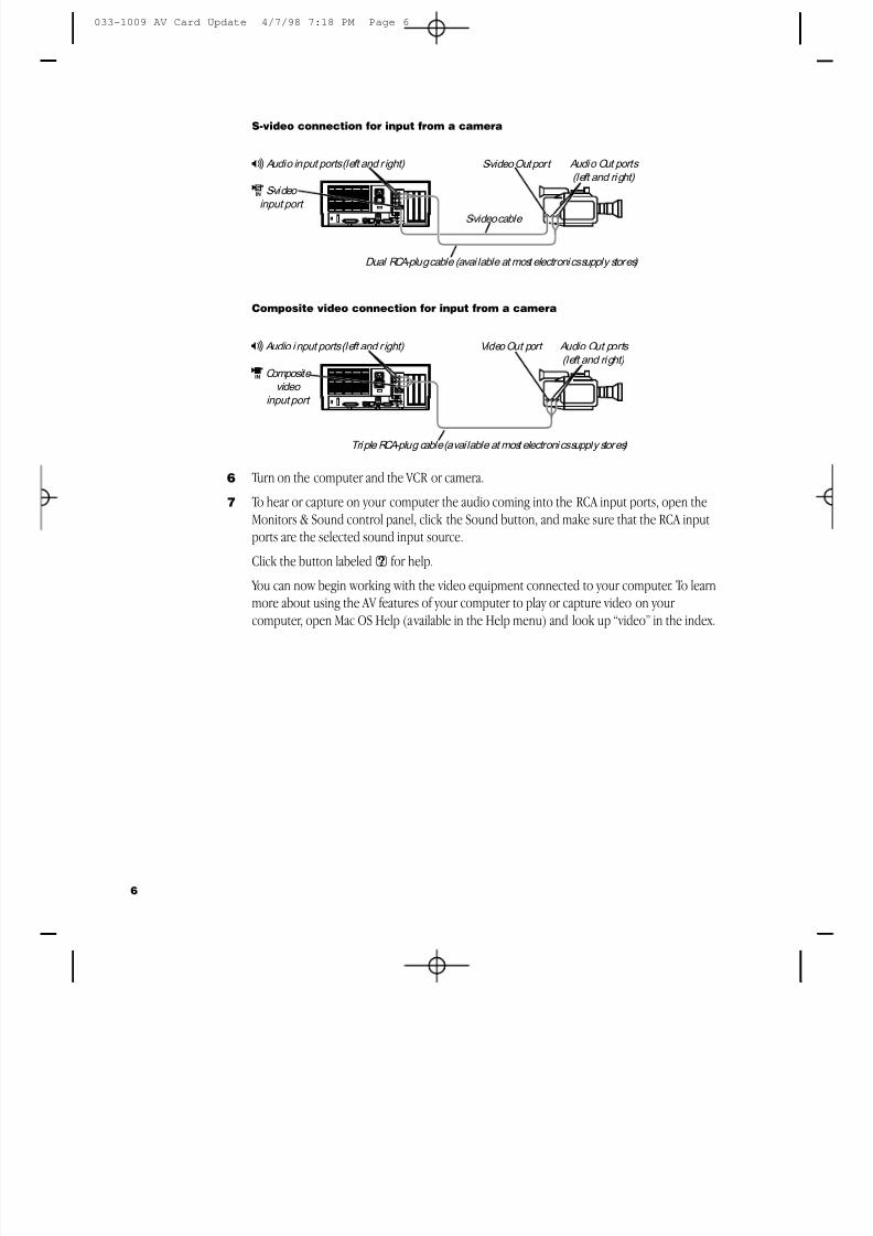
8/19/2019 Powermac Server g3 Minitower
http://slidepdf.com/reader/full/powermac-server-g3-minitower 278/292
S-video connection for input from a camera
Composite video connection for input from a camera
6 Turn on the computer and the VCR or camera.
7 To hear or capture on your computer the audio coming into the RCA input ports, open theMonitors & Sound control panel, click the Sound button, and make sure that the RCA inputports are the selected sound input source.
Click the button labeledh for help.
You can now begin working with the video equipment connected to your computer. To learnmore about using the AV features of your computer to play or capture video on your computer, open Mac OS Help (available in the Help menu) and look up “video” in the index.
Video Out port Audio Out ports (left and right)
Composite video
input port
Audio i nput ports (left and r ight)
˜
-
Triple RCA-plug cable (available at most electroni cs supply stores)
S-video Out port Audio Out ports (left and ri ght)
S-video cable
S-video
input port
æ
Audio input ports (left and r ight)
Dual RCA-plug cable (avai lable at most electronics supply stores)
-
6
033-1009 AV Card Update 4/7/98 7:18 PM Page 6
8/19/2019 Powermac Server g3 Minitower
http://slidepdf.com/reader/full/powermac-server-g3-minitower 279/292
Connecting Video Equipment for Output From the Computer
You can connect a VCR to record computer images and audio on videotape. The VCR record what is happening on the computer’s monitor, sounds generated by the computer, andspeech spoken into a microphone if one is connected. This capability is useful for creating
video presentations or software demonstrations.Note: The video out ports are primarily intended for recording what is happening on thecomputer’s monitor. You can use video-editing software to save captured and edited videoon a VCR if the video-editing software supports the use of a single monitor. However, to getfull video-editing support with independent monitor and video (or TV) output, you need topurchase and install a third-party video capture PCI card.
To connect a VCR for output from the computer, do the following:
1 Shut down the Macintosh and turn off the VCR.
2 Attach one end of the video cable to the Video In port on the VCR.
Follow the directions that came with the VCR.
3 Plug the other end of the video cable into either the S-video output port ( Æ ) or the yellow composite video output port ( Â ) on the Macintosh.
If the S-video connector doesn’t slide easily into the port, check the pin alignment and try again. Don’t use force, which could damage the computer or cable.
4 Plug the RCA-type connectors on the audio cables into the left and right Audio In ports onthe VCR.
5 Plug the RCA-type connectors on the audio cables into the left and right audio output ports( - ) on the Macintosh.
If the cable is color-coded, the red connector is for the right port, and the black or whiteconnector is for the left port.
7
033-1009 AV Card Update 4/7/98 7:18 PM Page 7
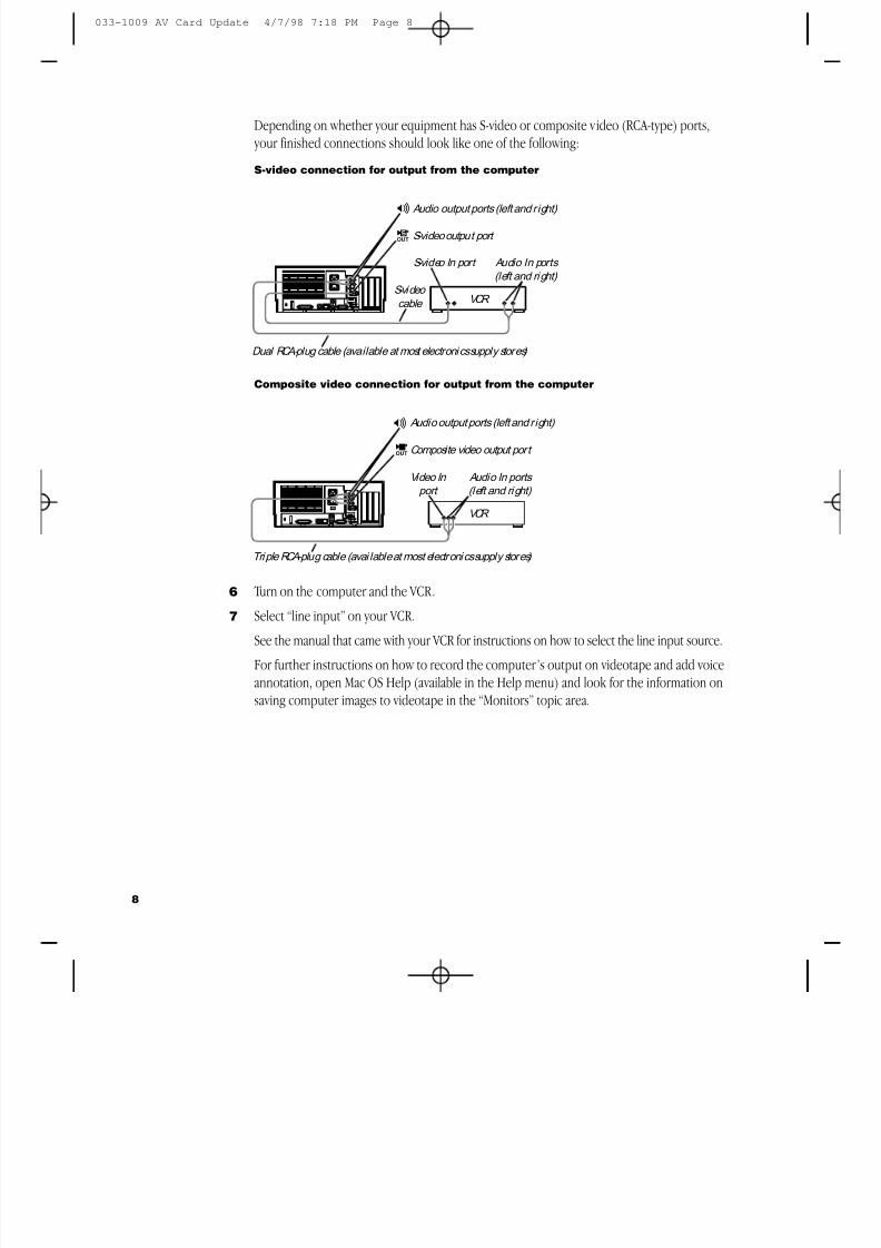
8/19/2019 Powermac Server g3 Minitower
http://slidepdf.com/reader/full/powermac-server-g3-minitower 280/292
Depending on whether your equipment has S-video or composite video (RCA-type) ports, your finished connections should look like one of the following:
S-video connection for output from the computer
Composite video connection for output from the computer
6 Turn on the computer and the VCR.
7Select “line input” on your VCR.See the manual that came with your VCR for instructions on how to select the line input source.
For further instructions on how to record the computer’s output on videotape and add voiceannotation, open Mac OS Help (available in the Help menu) and look for the information onsaving computer images to videotape in the “Monitors” topic area.
Video In port
Audio In ports (left and ri ght)
VCR
Composite video output port
Audio output ports (left and right)
Triple RCA-plug cable (avai lable at most electroni cs supply stores)
Â-
S-video output port
Audio output ports (left and right)
S-video In port Audio In ports (left and ri ght)
VCR
Æ-
S-video cable
Dual RCA-plug cable (available at most electroni cs supply stores)
8
033-1009 AV Card Update 4/7/98 7:18 PM Page 8
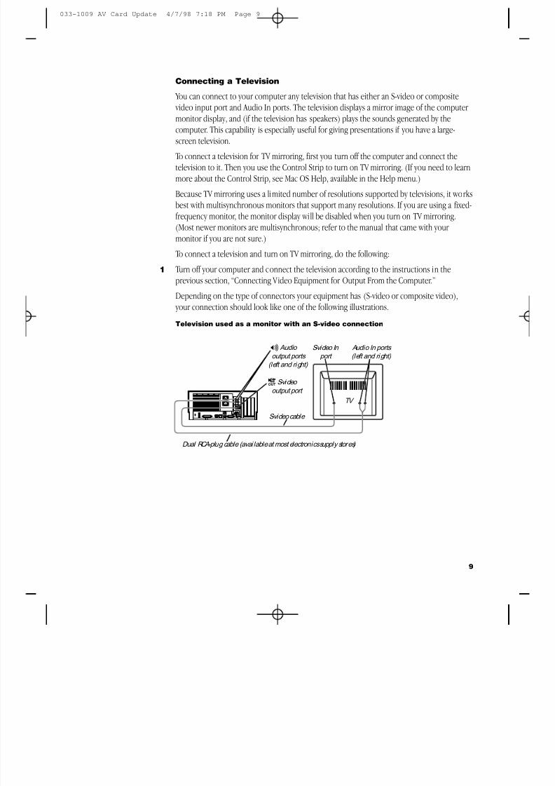
8/19/2019 Powermac Server g3 Minitower
http://slidepdf.com/reader/full/powermac-server-g3-minitower 281/292
Connecting a Television
You can connect to your computer any television that has either an S-video or composite video input port and Audio In ports. The television displays a mirror image of the computer monitor display, and (if the television has speakers) plays the sounds generated by the
computer. This capability is especially useful for giving presentations if you have a large-screen television.
To connect a television for TV mirroring, first you turn off the computer and connect thetelevision to it. Then you use the Control Strip to turn on TV mirroring. (If you need to learnmore about the Control Strip, see Mac OS Help, available in the Help menu.)
Because TV mirroring uses a limited number of resolutions supported by televisions, it workbest with multisynchronous monitors that support many resolutions. If you are using a fixed-frequency monitor, the monitor display will be disabled when you turn on TV mirroring.(Most newer monitors are multisynchronous; refer to the manual that came with your monitor if you are not sure.)
To connect a television and turn on TV mirroring, do the following:
1 Turn off your computer and connect the television according to the instructions in theprevious section, “Connecting Video Equipment for Output From the Computer.”
Depending on the type of connectors your equipment has (S-video or composite video), your connection should look like one of the following illustrations.
Television used as a monitor with an S-video connection
TV
S-video cable
S-video In port
Audio In ports (left and ri ght)
S-video
output port
Audio output ports
(left and ri ght)
Æ
-
Dual RCA-plug cable (avai lable at most electronics supply stores)
9
033-1009 AV Card Update 4/7/98 7:18 PM Page 9
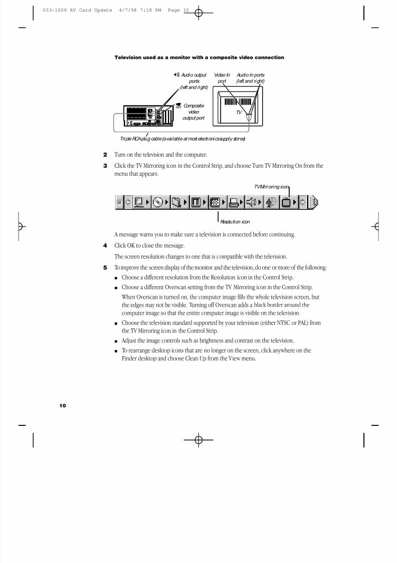
8/19/2019 Powermac Server g3 Minitower
http://slidepdf.com/reader/full/powermac-server-g3-minitower 282/292
Television used as a monitor with a composite video connection
2 Turn on the television and the computer.
3 Click the TV Mirroring icon in the Control Strip, and choose Turn TV Mirroring On from themenu that appears.
A message warns you to make sure a television is connected before continuing.
4 Click OK to close the message.
The screen resolution changes to one that is compatible with the television.
5 To improve the screen display of the monitor and the television, do one or more of the following:m Choose a different resolution from the Resolution icon in the Control Strip.m Choose a different Overscan setting from the TV Mirroring icon in the Control Strip.
When Overscan is turned on, the computer image fills the whole television screen, butthe edges may not be visible. Turning off Overscan adds a black border around thecomputer image so that the entire computer image is visible on the television.
m Choose the television standard supported by your television (either NTSC or PAL) fromthe TV Mirroring icon in the Control Strip.
m Adjust the image controls such as brightness and contrast on the television.m To rearrange desktop icons that are no longer on the screen, click anywhere on the
Finder desktop and choose Clean Up from the View menu.
TV Composite
video output port
Audio output ports
(left and right)
Video In port
Audio In ports (left and ri ght)
Triple RCA-plug cable (available at most electronics supply stores)
Â
-
10
Resolution icon
TV Mirroring icon
033-1009 AV Card Update 4/7/98 7:18 PM Page 10
8/19/2019 Powermac Server g3 Minitower
http://slidepdf.com/reader/full/powermac-server-g3-minitower 283/292
To turn off TV Mirroring, click the TV Mirroring icon in the Control Strip, and choose Turn Mirroring Off from the menu that appears.
Power Macintosh AV Card Specifications
Video Inputm Type: composite or S-videom Standards supported: NTSC, PAL, and SECAMm Resolution supported: 320 x 240, which scales to any size up to the size of the monitor m Polarity: sync negativem Voltage level: 0.7 V pp minimum, 1.0 V pp typical, 1.4 V pp maximumm Impedance: 75 ohms ( Ω ) internally terminated
Video Output
m Type: composite and S-videom Standards supported: NTSC and PALm Resolutions supported: 512 x 384, 640 x 480, 800 x 600, and 832 x 624m Polarity: sync negative (no sync on S-video chroma signal)m Voltage level: 1.0 V pp ±5% into a 75Ω resistive load (S-video chroma 0.7 V pp )m Impedance: 75Ω source
Sound input using the RCA-type audio input ports
m Input impedance (preampli fier off): more than 80 kΩ
m Maximum input voltage (preamplifier off): 1 V rms= 2.8 Volts peak-to-peak (V pp ), nominalm Input impedance (preamplifier on): more than 5 kΩ
m Maximum input voltage (preamplifier on): 62 millivolts (mV rms ) = 175 mV pp, nominal
Sound output using the optional RCA-type audio output ports
m Output impedance: 400Ω
m Maximum output voltage: 1 V rms= 2.8 V pp, nominal
Noise, distortion, and bandwidth
m Audio input signal-to-noise ratio (SNR): 85 decibels (dB) unweighted (add +8 dB toestimate A weighting)
m Total harmonic distortion: 0.05%m Bandwidth: 20 Hz–20 kHz at 44.1-kHz sample rate (Other sample rates scale the upper
cutoff frequency.)
11
033-1009 AV Card Update 4/7/98 7:18 PM Page 11
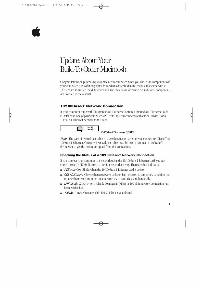
8/19/2019 Powermac Server g3 Minitower
http://slidepdf.com/reader/full/powermac-server-g3-minitower 284/292
Update: About YourBuild-To-Order MacintoshCongratulations on purchasing your Macintosh computer. Since you chose the components of your computer, parts of it may differ from what’s described in the manual that came with it.This update addresses the differences and also includes information on additional components
not covered in the manual.
10/100Base-T Network Connection
If your computer came with the 10/100Base-T Ethernet option, a 10/100Base-T Ethernet cardis installed in one of your computer’s PCI slots. You can connect a cable for a 10Base-T or a100Base-T Ethernet network to this card.
Note: The type of twisted-pair cable you use depends on whether you connect to 10Base-T or
100Base-T Ethernet. Category 5 twisted-pair cable must be used to connect to 100Base-Tif you want to get the maximum speed from this connection.
Checking the Status of a 10/100Base-T Network Connection
If you connect your computer to a network using the 10/100Base-T Ethernet card, you cancheck the card’s LED indicators to monitor network activity. There are four indicators:m ACT (Activity): Blinks when the 10/100Base-T Ethernet card is activem COL (Coll ision): Glows when a network collision has occurred (a temporary condition that
occurs when two computers on a network try to send data simultaneously)m LNK (Link): Glows when a reliable 10 megabit (Mbit) or 100 Mbit network connection has
been establishedm 100 Mb: Glows when a reliable 100 Mbit link is established
10/100Base-T Ethernet port (RJ-45)
1
3-0926.BTO Update 4/7/98 6:45 PM Page 1
8/19/2019 Powermac Server g3 Minitower
http://slidepdf.com/reader/full/powermac-server-g3-minitower 285/292
10/100Base-T Ethernet Card Specifications
m Open Transport: Mac OS 7.5.2 or later, AppleShare, AppleTalk, NetWare for Macintosh, TCP/IPm Connector: RJ-45 (for 10Base-T and 100Base-T)m
Media, 10Base-T: Cat 3, 4, or 5 UTP on 2 pairs up to 100 meters (m)m Media, 100Base-T: Cat 5 UTP on 2 pairs up to 100 mm Bus interface: PCI revision 2.0 and 2.1, share interrupt A m Channel speeds: IEEE Auto Negotiation of 10Base-T and 100Base-Tm Communications: IEEE 802.3u 100Base-T; IEEE 802.3i 10Base-Tm Controllers: DECchip 21140, 32-bit internal processor per channelm Power: 1.2 amperes (A) @ 5 volts (V) typical
Ultra Wide SCSI Hard Disk Drive and PCI Card
If your computer came with an Ultra Wide SCSI hard disk drive, it includes some or all of thefollowing components:m an internal Ultra Wide SCSI hard disk drivem in certain configurations, additional internal Ultra Wide SCSI hard disk drivesm an Ultra Wide SCSI card in one of your computer’s PCI slotsm an internal Ultra Wide SCSI cable that supports up to three internal devices (including your
pre-installed Ultra Wide hard disks)
Warning Do not connect any SCSI devices to the external 68-pin SCSI-3 connector or to the internal 50-pin SCSI-2 connector on the PCI card that supports the internal harddisk. Connecting even one external SCSI device to the external 68-pin connector
extends the overall cable length of the SCSI bus beyond the limit for which error-freeoperation can be guaranteed; the combined length of the internal cable and theexternal cable reduces the reliability of all the devices connected to the Ultra WideSCSI bus. Connecting a device to the internal 50-pin SCSI-2 connector will cause your Ultra Wide SCSI devices to transfer data at the slower, SCSI-2 rate.
2
3-0926.BTO Update 4/7/98 6:45 PM Page 2
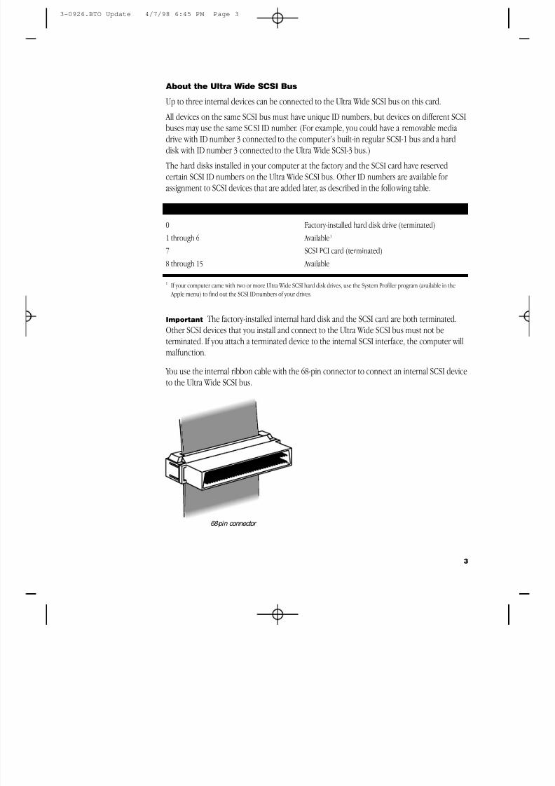
8/19/2019 Powermac Server g3 Minitower
http://slidepdf.com/reader/full/powermac-server-g3-minitower 286/292
3
About the Ultra Wide SCSI Bus
Up to three internal devices can be connected to the Ultra Wide SCSI bus on this card.
All devices on the same SCSI bus must have unique ID numbers, but devices on different SCSI
buses may use the same SCSI ID number. (For example, you could have a removable mediadrive with ID number 3 connected to the computer’s built-in regular SCSI-1 bus and a harddisk with ID number 3 connected to the Ultra Wide SCSI-3 bus.)
The hard disks installed in your computer at the factory and the SCSI card have reservedcertain SCSI ID numbers on the Ultra Wide SCSI bus. Other ID numbers are available for assignment to SCSI devices that are added later, as described in the following table.
Ultra Wide SCSI ID Number Device
0 Factory-installed hard disk drive (terminated)1 through 6 Available1
7 SCSI PCI card (terminated)
8 through 15 Available
1 If your computer came with two or more Ultra Wide SCSI hard disk drives, use the System Profiler program (available in the Apple menu) to find out the SCSI ID numbers of your drives.
Important The factory-installed internal hard disk and the SCSI card are both terminated.Other SCSI devices that you install and connect to the Ultra Wide SCSI bus must not beterminated. If you attach a terminated device to the internal SCSI interface, the computer willmalfunction.
You use the internal ribbon cable with the 68-pin connector to connect an internal SCSI deviceto the Ultra Wide SCSI bus.
68-pin connector
3-0926.BTO Update 4/7/98 6:45 PM Page 3
8/19/2019 Powermac Server g3 Minitower
http://slidepdf.com/reader/full/powermac-server-g3-minitower 287/292
Ultra Wide SCSI Card Specifications
m Automatic terminationm Advanced Data Streaming Technology (ADS)m
RAID-ready m Embedded RISC I/P processor m Ultra SCSI connector: Fine pitch 68-pin “P”m Flash ROM BIOSm PCI 2.1 compliantm Large command FIFOm Supports disconnect/reconnectm Asynchronous I/O supportm Multiple initiator supportm SCSI-3 tagged command queuing
m SCSI Manager 4.3 compatible
RAID Disk Volume Management Software
Certain Power Macintosh G3 configurations are supplied with RAID disk volume managementsoftware. This software enables your hard disk drives to be striped or mirrored.
The RAID CD can be used as a startup disk. You can restart from it and use the RAIDapplication to initialize and stripe or mirror your hard disks. You can also use the RAID Installeto place a copy of the RAID application on one of your hard disks.
To restart your computer from the RAID CD, insert the CD and hold down the C key while
you restart.Refer to the documentation supplied on the RAID CD for full instructions on how to set upand maintain RAID volumes.
4
3-0926.BTO Update 4/7/98 6:45 PM Page 4
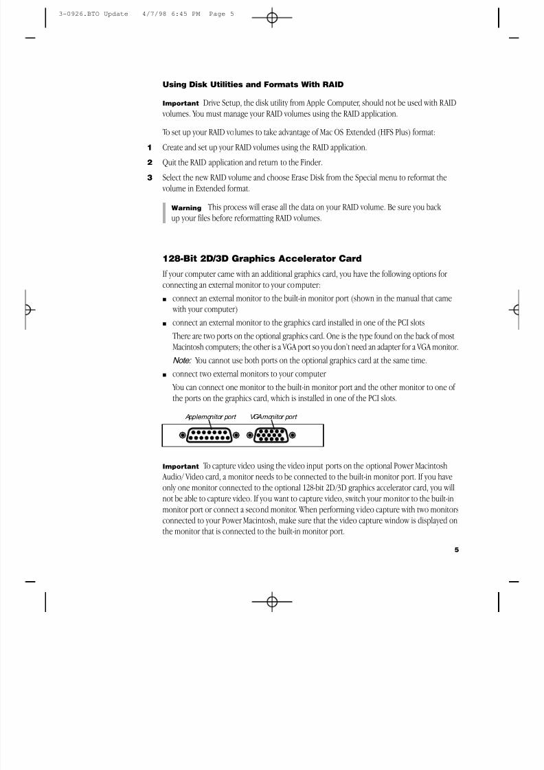
8/19/2019 Powermac Server g3 Minitower
http://slidepdf.com/reader/full/powermac-server-g3-minitower 288/292
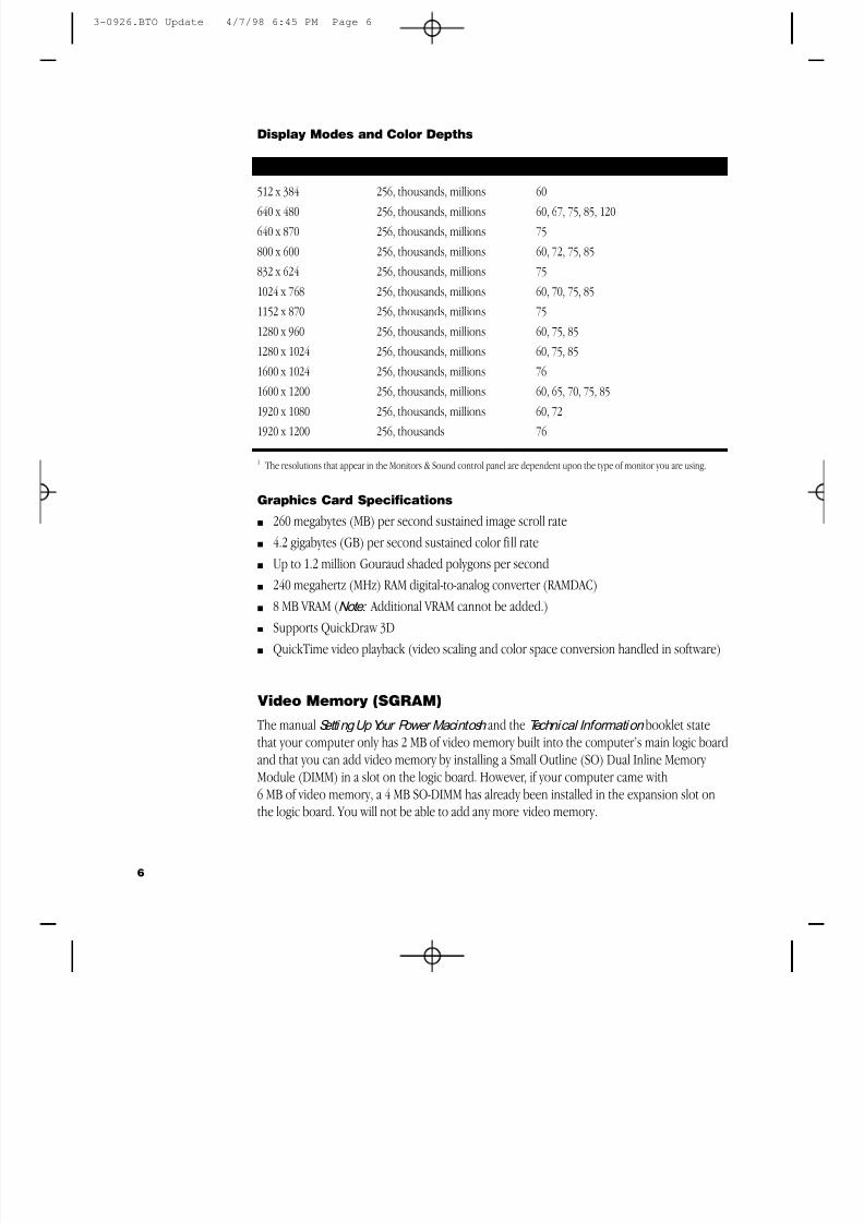
8/19/2019 Powermac Server g3 Minitower
http://slidepdf.com/reader/full/powermac-server-g3-minitower 289/292
Display Modes and Color Depths
Resolution 1 Color Depths Vertical Refresh Rate (Hertz)
512 x 384 256, thousands, millions 60640 x 480 256, thousands, millions 60, 67, 75, 85, 120640 x 870 256, thousands, millions 75800 x 600 256, thousands, millions 60, 72, 75, 85832 x 624 256, thousands, millions 751024 x 768 256, thousands, millions 60, 70, 75, 851152 x 870 256, thousands, millions 751280 x 960 256, thousands, millions 60, 75, 851280 x 1024 256, thousands, millions 60, 75, 851600 x 1024 256, thousands, millions 761600 x 1200 256, thousands, millions 60, 65, 70, 75, 85
1920 x 1080 256, thousands, millions 60, 721920 x 1200 256, thousands 76
1 The resolutions that appear in the Monitors & Sound control panel are dependent upon the type of monitor you are using.
Graphics Card Specifications
m 260 megabytes (MB) per second sustained image scroll ratem 4.2 gigabytes (GB) per second sustained color fill ratem Up to 1.2 million Gouraud shaded polygons per secondm 240 megahertz (MHz) RAM digital-to-analog converter (RAMDAC)
m 8 MB VRAM ( Note: Additional VRAM cannot be added.)m Supports QuickDraw 3Dm QuickTime video playback (video scaling and color space conversion handled in software)
Video Memory (SGRAM)
The manualSetti ng Up Your Power Macintosh and theTechnical Information booklet statethat your computer only has 2 MB of video memory built into the computer’s main logic boardand that you can add video memory by installing a Small Outline (SO) Dual Inline Memory Module (DIMM) in a slot on the logic board. However, if your computer came with6 MB of video memory, a 4 MB SO-DIMM has already been installed in the expansion slot on
the logic board. You will not be able to add any more video memory.
6
3-0926.BTO Update 4/7/98 6:45 PM Page 6
8/19/2019 Powermac Server g3 Minitower
http://slidepdf.com/reader/full/powermac-server-g3-minitower 290/292
Apple FireWire Card
The optional Apple FireWire Card is designed to work with digital video camcorders and decksthat use the DV format and have a FireWire port (sometimes marked IEEE 1394 or DV IN/OUTThe included hardware and software, together with a non-linear editing application, allow youto capture DV movie clips to your hard disk. You can view the clips in MoviePlayer or other QuickTime 3.0 applications, and edit and render the DV movies. If you are using a videoediting application with an export function, you can send (print or record) movies back to thetape in your camcorder or deck. The software also allows the FireWire device to be controlledfrom the computer.
The FireWire Bus
FireWire is a serial bus that can support high-performance devices, such as DV cameras andprinters. Devices can be connected in any combination of branching and chaining, as long asno loops are formed. A FireWire bus can support up to 16 consecutive cable hops of 4.5 meterseach. There are no SCSI-style ID numbers to set and no termination requirements.
The Apple FireWire Card is designed to keep the network alive even if the Macintosh is shutdown. Loss of power to the Macintosh will not affect the operation of a FireWire card as long ait can draw power from other cards on the bus.
Each card provides power which is available to other devices on the network. This means thata system shutdown will not result in interrupted transmission over a FireWire network.
Important For more information about cable management and power issues, please refer tothe FireWire ReadMe file on the FireWire CD.
Apple FireWire Hardware
If you ordered the Apple FireWire Card with your computer, you have received the followingitems:m the Apple FireWire Card, installed in one of your computer’s PCI slotsm a FireWire cable, 4-pin to 6-pin, 2 meters longm a FireWire software installation CD
Your Apple FireWire Card has three FireWire ports, as shown in the following illustration.
7
3-0926.BTO Update 4/7/98 6:45 PM Page 7
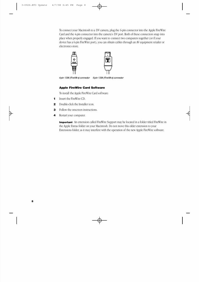
8/19/2019 Powermac Server g3 Minitower
http://slidepdf.com/reader/full/powermac-server-g3-minitower 291/292
To connect your Macintosh to a DV camera, plug the 6-pin connector into the Apple FireWireCard and the 4-pin connector into the camera’s DV port. Both of these connectors snap intoplace when properly engaged. If you want to connect two computers together (or if your device has a 6-pin FireWire port), you can obtain cables through an AV equipment retailer or
electronics store.
Apple FireWire Card Software
To install the Apple FireWire Card software:1 Insert the FireWire CD.
2 Double-click the Installer icon.
3 Follow the onscreen instructions.
4 Restart your computer.
Important An extension called FireWire Support may be located in a folder titled FireWire inthe Apple Extras folder on your Macintosh. Do not move this older extension to your Extensions folder, as it may interfere with the operation of the new Apple FireWire software.
4-pin 1394 (FireWir e) connector 6-pin 1394 (FireWir e) connector
8
3-0926.BTO Update 4/7/98 6:45 PM Page 8
8/19/2019 Powermac Server g3 Minitower
http://slidepdf.com/reader/full/powermac-server-g3-minitower 292/292