Embed Size (px)
Citation preview

U.S. Department of the Interior Bureau of Reclamation Research and Development Office Denver, Colorado September 2017
Technical Memorandum No. 8540-2017-012
Powering Cathodic Protection Systems with Alternative Energy Research and Development Office Science and Technology Program Final Report ST-2017-1718-01


The public reporting burden for this collection of information is estimated to average 1 hour per response, including the time for reviewing instructions, searching existing data sources, gathering and maintaining the data needed, and completing and reviewing the collection of information. Send comments regarding this burden estimate or any other aspect of this collection of information, including suggestions for reducing the burden, to Department of Defense, Washington Headquarters Services, Directorate for Information Operations and Reports (0704-0188), 1215 Jefferson Davis Highway, Suite 1204, Arlington, VA 22202-4302. Respondents should be aware that notwithstanding any other provision of law, no person shall be subject to any penalty for failing to comply with a collection of information if it does not display a currently valid OMB control number.
PLEASE DO NOT RETURN YOUR FORM TO THE ABOVE ADDRESS T1. REPORT DATE
September 2017 T2. REPORT TYPE
Research T3. DATES COVERED
Dec 2016 - Sep 2017 T4. TITLE AND SUBTITLE
Powering Cathodic Protection Systems with Alternative Energy 5a. CONTRACT NUMBER
17XR0680A1-RY15412017IS11718 5b. GRANT NUMBER 5c. PROGRAM ELEMENT NUMBER
1541 6. AUTHOR(S)
Kelly Ramaeker, Lise Gentry, Atousa Plaseied
Bureau of Reclamation Denver Federal Center PO Box 25007 Denver, CO 80225-0007
5d. PROJECT NUMBER 1718
5e. TASK NUMBER 5f. WORK UNIT NUMBER
86-68540 7. PERFORMING ORGANIZATION NAME(S) AND ADDRESS(ES)
Bureau of Reclamation Materials & Corrosion Laboratory PO Box 25007 (86-68540) Denver, Colorado 80225
8. PERFORMING ORGANIZATION REPORT NUMBER 8540-2017-012
9. SPONSORING / MONITORING AGENCY NAME(S) AND ADDRESS(ES) Research and Development Office U.S. Department of the Interior, Bureau of Reclamation, PO Box 25007, Denver CO 80225-0007
10. SPONSOR/MONITOR’S ACRONYM(S) R&D: Research and Development Office BOR/USBR: Bureau of Reclamation DOI: Department of the Interior
11. SPONSOR/MONITOR’S REPORT NUMBER(S) ST-2017-1718-01
12. DISTRIBUTION / AVAILABILITY STATEMENT Final report can be downloaded from Reclamation’s website: https://www.usbr.gov/research/
13. SUPPLEMENTARY NOTES
14. ABSTRACT The goal for this study was to identify commercial and more cost effective alternative energy sources to the existing ones that will still allow ICCP systems to meet their operating requirements. Five commercially available alternative power sources as potential sources of power for ICCP systems at Reclamation were evaluated. Of all the alternative energy sources investigated, solar power appears to provide the best fit as the primary alternative power source, although it can be dependent on the site having good solar resources. The higher variability of wind power with low wind turbine elevations and the desire to minimize visual impact makes it less desirable in locations with good solar resources. TEGs, fossil fuel combustion generators, and fuel cells require significant staff involvement on an ongoing basis at the sites.
15. SUBJECT TERMS Cathodic Protection, Alternative Energy, Solar, Wind, Thermoelectric Generator, Fuel Cell
16. SECURITY CLASSIFICATION OF: U
17. LIMITATION OF ABSTRACT
U
18. NUMBER OF PAGES
59
19a. NAME OF RESPONSIBLE PERSON William Kepler
a. REPORT U
b. ABSTRACT U
c. THIS PAGE U
19b. TELEPHONE NUMBER 303-445-2386
Standard Form 298 (Rev. 8/98) Prescribed by ANSI Std. Z39.18


Technical Memorandum No. 8540-2017-012
Powering Cathodic Protection Systems with Alternative Energy Research and Development Office Science and Technology Program Final Report ST-2017-1718-01

Disclaimer Information in this report may not be used for advertising or promotional purposes. The data and findings should not be construed as an endorsement of any product or firm by the Bureau of Reclamation, the Department of the Interior, or the Federal Government. The products evaluated in this report were evaluated for purposes specific to the Bureau of Reclamation mission. Reclamation gives no warranties or guarantees, expressed or implied, for the products evaluated in this report, including merchantability or fitness for a particular purpose.
Mission Statements The U.S. Department of the Interior protects America’s natural resources and heritage, honors our cultures and tribal communities, and supplies the energy to power our future. The mission of the Bureau of Reclamation is to manage, develop, and protect water and related resources in an environmentally and economically sound manner in the interest of the American public.

Prepared: Atousa Plaseied, Ph.D., P.E. Civil Engineer, Water Conveyance Group, 86-68140 Date


Peer Review Documentation From TSC Guidelines: http://intra.do.usbr.gov/~tsc/guidance/operating/op-guide.pdf (page 18)
Project and Document Information
Project Name
Powering Cathodic Protection Systems with Alternative Energy
WOID Z1718
Document Powering Cathodic Protection Systems with Alternative Energy
Document Date September 2017
Document Author/Preparer Kelly Ramaeker, Lisa Gentry, P.E., Atousa Plaseied, Ph.D., P.E.
Peer Reviewer William Kepler, Ph.D., P.E.
For Reclamation disseminated reports, a disclaimer is required for final reports and other research products, this language can be found in the peer review policy: "This information is distributed solely for the purpose of pre-dissemination peer review under applicable information quality guidelines. It has not been formally disseminated by the Bureau of Reclamation. It does not represent and should not be construed to represent Reclamation's determination or policy."
Review Certification
Peer Reviewer: I have reviewed the assigned items/sections(s) noted for the above document and believe them to be in accordance with the project requirements, standards of the profession, and Reclamation policy.
Reviewer Signature
Date Reviewed


Technical Memorandum No. 8540-2017-012 Powering Cathodic Protection Systems with Alternative Energy
Final Report ST-2017-1718-01
i
Executive Summary The purpose of this scoping study is to identify commercial and more cost effective alternative energy sources to the existing ones that will allow impressed current cathodic protection (ICCP) systems to meet their operating requirements. This study is a comprehensive literature review containing:
• Requirements for ICCP system power sources, including component redundancy requirements and backup power requirements.
• Alternative energy sources which would meet the operating criteria for ICCP power sources.
• Cost evaluations for each alternative energy source and cost comparison against traditional utility provided electric power connections.
Providing utility supplied cathodic protection (CP) power sources can often be prohibitively expensive in rural and isolated areas. A need for more cost efficient power sources is pushing the Bureau of Reclamation (Reclamation) to consider alternative energy sources with new installations. It is important to understand the capabilities of the alternative energy source and needs of the CP system to prevent use of a system in an application for which it is not well suited. While alternative energy sources are available, Reclamation does not have experience in installing or operating them for ICCP applications. This can cause problems in deploying these sources for the first time due to the unique challenges non-utility based power supplies can face. This study evaluates five commercially available alternative power sources (solar power supply, fossil fuel combustion engine generator supply, thermoelectric generator supply, wind turbine supply, and fuel cell supply) as potential sources of power for ICCP systems at Reclamation. In addition to evaluating the power supply options based on the listed criteria, there is also a brief description of each power supply option and some of the general challenges that are faced in their implementation. We need to continue studying these technologies as Reclamation moves closer to deploying them.

Technical Memorandum No. 8540-2017-012 Powering Cathodic Protection Systems with Alternative Energy Final Report ST-2017-1718-01
ii
Acknowledgements The authors are grateful for funding support from the Bureau of Reclamation Science and Technology Program.

Technical Memorandum No. 8540-2017-012 Powering Cathodic Protection Systems with Alternative Energy
Final Report ST-2017-1718-01
iii
Acronyms and Abbreviations °C degree Celsius °F degree Fahrenheit A ampere AC alternating current AGS automatic generator start Ah ampere-hour a-Si amorphous silicon ASTM American Society for Testing and Materials CdTe cadmium telluride CIS/CIGS copper indium gallium selenide Cp coefficient of power CO2 carbon dioxide CP cathodic protection CSP concentrated solar power DC direct current DOD depth of discharge gph gallons per hour GTEG gas fuel thermoelectric generator ICCP impressed current cathodic protection IEC International Electrochemical Commission IEEE Institute of Electrical and Electronics Engineers in inch kg kilogram kW kilowatt kWh kilowatt hour mA milliampere mA/m2 milliampere/square meter mm Millimeter MPPT maximum power point tracking mV millivolt

Technical Memorandum No. 8540-2017-012 Powering Cathodic Protection Systems with Alternative Energy Final Report ST-2017-1718-01
iv
MW megawatt NEMA National Electrical Manufacturers Association NFPA National Fire Protection Association NM New Mexico NREL National Renewable Energy Laboratory OPC organic photovoltaic cell PEM polymer electrolyte membrane PG&E Pacific Gas and Electric Company psi pounds per square inch PV photovoltaic PWM pulse width modulation Reclamation Bureau of Reclamation SGS Small General Service SiN silicon nitride SOC solid oxide cell SOFC solid oxide fuel cell TEG thermoelectric generator TFPV thin-film photovoltaic cell U.S. United States V volt VDC volts direct current VA volt-ampere VPC volts per cell W watts WA Washington (State)

Technical Memorandum No. 8540-2017-012 Powering Cathodic Protection Systems with Alternative Energy
Final Report ST-2017-1718-01
v
Contents Page
Introduction ............................................................................................................9 Components of the Impressed Current System ..................................................9 Operating Requirements of Impressed Current Cathodic Protection Systems 10 Power Sources ..................................................................................................11
Utility Supply ........................................................................................................11 System Arrangement ........................................................................................11 Reliability .........................................................................................................12 Maintainability .................................................................................................12 Relative Cost ....................................................................................................13
Installation..................................................................................................13 Operation....................................................................................................13
Solar Power Supply..............................................................................................13 System Arrangement ........................................................................................13 Conditions Impacting Solar Photovoltaic Installations....................................14 Sizing Solar Power Supplies ............................................................................18 Components .....................................................................................................19
Solar Panels ................................................................................................19 Charge Controller.......................................................................................19 Batteries .....................................................................................................20
Reliability .........................................................................................................20 Maintainability .................................................................................................20 Relative Cost ....................................................................................................20
Installation..................................................................................................20 Operation....................................................................................................21
Standards for Solar Panel Systems and Specific Batteries ..............................22 Resources and Manufacturers ..........................................................................22
Fossil Fuel Combustion Engine Generator Supply...........................................24 System Arrangement ........................................................................................24 Fuel Types ........................................................................................................26 Reliability .........................................................................................................26 Maintainability .................................................................................................27 Relative Cost ....................................................................................................27
Installation..................................................................................................27 Operation....................................................................................................28
Standards for Generators..................................................................................29 Resources and Manufacturers ..........................................................................29
Thermoelectric Generator Supply......................................................................29 System Arrangement ........................................................................................29

Technical Memorandum No. 8540-2017-012 Powering Cathodic Protection Systems with Alternative Energy Final Report ST-2017-1718-01
vi
Reliability .........................................................................................................30 Maintainability .................................................................................................30 Relative Cost ....................................................................................................30 Resources and Manufacturers ..........................................................................31
Wind Turbine Generator Supply .......................................................................31 System Arrangement ........................................................................................31 Conditions Impacting Wind Turbine Installations ...........................................32 Reliability .........................................................................................................37 Maintainability .................................................................................................37 Relative Cost ....................................................................................................37
Installation..................................................................................................37 Operation....................................................................................................38
Standards for Wind Turbines ...........................................................................39
Fuel Cell Supply ...................................................................................................39 System Arrangement ........................................................................................39 Reliability .........................................................................................................40 Maintainability .................................................................................................40 Relative Cost ....................................................................................................40 Resources/Manufacturers for Fuel Cells ..........................................................41
Summary ...............................................................................................................41
References .............................................................................................................45
Tables Table 1.—Power Source Summary........................................................................43
Figures Figure 1.—Typical impressed current cathodic protection ....................................10
Figure 2.—Typical utility distribution arrangement ..............................................12
Figure 3.—Typical solar arrangement for CP application .....................................14
Figure 4.—Alternate solar arrangement for CP application ..................................14
Figure 5.—PV solar resources of the U.S. [6] .......................................................16
Figure 6.—Mean monthly cloudy days for Albuquerque, NM [9] ........................17
Figure 7.—Mean monthly cloudy days for Seattle, WA [9] ..................................17

Technical Memorandum No. 8540-2017-012 Powering Cathodic Protection Systems with Alternative Energy
Final Report ST-2017-1718-01
vii
Figure 8.—CP system installed for Chevron Oil with (a) 245 W modules, batteries, and charge controllers in Utah, and (b) 20 A output in Colorado, reproduced from [23] .................................................................................23
Figure 9.—Sunpole solar panel system, reproduced from (Farwest Corrosion Control Company, n.d.) .............................................................................23
Figure 10.—Typical generator arrangement for CP applications ..........................25
Figure 11.—A CP unit in Wyoming featuring both solar and wind power, reproduced from [23] .................................................................................32
Figure 12.—Typical DC-bus hybrid power system, reproduced from [42] ..........32
Figure 13.—Average annual wind speed at 80 m [43] ..........................................34
Figure 14.—Average annual wind speed at 30 m [43] ..........................................35
Figure 15.—Preliminary power and CP curves for the Gaia-Wind 11 kW [44] ....36
Figure 16.—Preliminary power and Cp curves for the ARE 442 [44] ...................36
Figure 17.— Diagrams of (a) polymer electrolyte membrane fuel cells (PEM) and (b) solid oxide fuel cells (SOFC), reproduced from [47] ...........................40
Figure 18.—Atrex Energy tubular SOFC technology, reproduced from [50] .......41


Technical Memorandum No. 8540-2017-012 Powering Cathodic Protection Systems with Alternative Energy
Final Report ST-2017-1718-01
9
Introduction The purchasing and installation of pipelines represent a significant portion of the project costs for water delivery and storage projects performed by the Bureau of Reclamation (Reclamation). Given these costs, it is important for the long term success of these installations to maximize the lifetime and use of the pipelines. For metallic components corrosion is a leading cause of premature failure and must be considered when designing the system. However, corrosion can be mitigated by many widely used commercially available products such as coating systems applied to the components and cathodic protection (CP) systems. The purpose of CP is to reduce the corrosion current flow on a metallic structure’s surface caused by the potential differences between local anodic and cathodic sites. This is accomplished by imposing current between the structure and an external electrode. The external current from the electrode polarizes the cathodic sites in the electronegative direction. Corrosion will halt when there is no longer a potential difference between the cathodic and anodic sites on a structure’s surface [1]. Standard utility-supplied power sources are by far the most common and generally the most economical power supply used for the power requirements of impressed current cathodic protection (ICCP) systems. Alternative power supplies including solar, wind, thermoelectric generators (TEGs), combustion engine generators, and fuel cells are available when connections to the alternating current (AC) power grid are unavailable (the pipeline is far away from a power line) or are prohibitively expensive. The goal of this scoping study is to identify commercial and more cost effective alternative energy sources to the existing ones that will still allow ICCP systems to meet their operating requirements.
Components of the Impressed Current System An ICCP system uses a power supply (rectifier) to generate large potential differences, enabling current to flow from the anode bed to the structure being protected. The components of an ICCP system are: anodes, a power supply (rectifier), structure, wiring, and connections (see Figure 1). A transformer-rectifier is a piece of equipment that steps down the AC voltage and then converts it to direct current (DC) voltage. If a DC power source with an appropriate current and voltage rating is supplied, then a rectifier is no longer required, and a variable resistor can be used.

Technical Memorandum No. 8540-2017-012 Powering Cathodic Protection Systems with Alternative Energy Final Report ST-2017-1718-01
10
Figure 1.—Typical impressed current cathodic protection
ICCP operates with an external power source paired with inert anodes. This system is often required for the protection of large surface areas or if the resistivity of the electrolyte is high. In ICCP systems, the amount of protection does not depend on the anode activity because of the paired external power source. Typically, DC output will be in the range 12 to 30 volts (V) and 5 to 20 ampere (A) (generally 20 V and 15 A or smaller for Reclamation projects). To ensure that enough current is being supplied for the protection of the metal structure, the power source for the ICCP system should be optimized on a system-by-system basis. Typically, a structure current density in the range of 11-22 mA/m2 is required for bare metal in soil. It is crucial to use ICCP systems continuously with a constant supply of electricity [2].
Operating Requirements of Impressed Current Cathodic Protection Systems In an impressed current system utilizing a rectifier, the power to the rectifier cannot be interrupted except when conducting maintenance or testing activities. Normally, a dedicated circuit is provided for the impressed current system so that the power cannot be inadvertently cut off [3]. Note that corrosion is not always going to happen without an ICCP system on, but is rather a possibility or probability. It means that there are pipes that have had the ICCP system off for years and a catastrophic failure has not occurred. However, at the same time there were failures in pipes in a short period of time with no ICCP on.

Technical Memorandum No. 8540-2017-012 Powering Cathodic Protection Systems with Alternative Energy
Final Report ST-2017-1718-01
11
Power interruption (caused by utility power failure, equipment failure, vandalism, or maintenance requirements) can lead to extensive corrosion of metallic surfaces and metal reinforcement, especially in high corrosive environments and, thus, a reliable source of power for the CP current is essential. A detailed evaluation of the impact of short duration power outages is not included in this report and would require further investigation.
Power Sources Anything that can provide an electric power supply of 15 A at 20 VDC is capable of acting as an energy source for an ICCP system. The operating requirements of an ICCP system impose additional conditions on the power source so that it can be capable of providing reliable power with few interruptions of power. Different energy sources achieve this, either by having high reliability in the primary energy supply or by having a combination of components, which provide high overall power reliability. A relative cost analysis is performed in this report for each of the energy supply options evaluated. The intent of this analysis to provide a general order of magnitude evaluation on the cost of the power supply installation. This evaluation does not include costs for the CP system, site preparation, or other installations on the site.
Utility Supply System Arrangement For utility supplied power the customer pays the electric power utility to bring a distribution power line to the location of the ICCP rectifier. If the location of the rectifier is near existing power lines, this cost might be minimal. If the location of the rectifier is a significant distance from available power lines, this cost can be extremely high. The cost to provide power to an individual location can be variable with connection costs anywhere from a thousand dollars to millions of dollars. This varies, based on the distance and amount of equipment required to be installed by the electric utility, as well as the pricing structure used by the utility. It is important when using utility supplied power to contact the utility company during the design process to evaluate the probable cost of the electrical connection. Utility supplied power sources require little equipment for the customer to supply beyond the point of interconnection. Generally these installations only require an

Technical Memorandum No. 8540-2017-012 Powering Cathodic Protection Systems with Alternative Energy Final Report ST-2017-1718-01
12
electric disconnect switch and some cable to connect the power source to the rectifier. See Figure 2 for a typical utility supply arrangement.
Figure 2.—Typical utility distribution arrangement
Reliability The reliability of a utility supplied power source is generally very high. As an example, electric utility Pacific Gas and Electric (PG&E) Company’s customers experienced on average a sustained outage of 95.8 minutes in 2015 [4]. Due to the high level of reliability backup power equipment, like batteries, are rarely supplied for ICCP systems designed by Reclamation.
Maintainability Utility sources require monthly visits to the site to perform a visual inspection of the power components. The type of components required for this system allow it to withstand a wide variety of environmental conditions.

Technical Memorandum No. 8540-2017-012 Powering Cathodic Protection Systems with Alternative Energy
Final Report ST-2017-1718-01
13
Relative Cost Installation As discussed earlier, the installation costs for utility power sources can be highly variable due to the cost of the utility connection.
Operation
The operating costs calculated below are based on the charges for a 15 A, 20 VDC load and the 2013 electric rates for Black Hills Energy [5]. Costs for labor and maintaining the system are not included in this evaluation.
Electric load: 300 watts (W) Utility charge (based on rate classification Small General Service (SGS) [5]):
Customer fee: $16.50/month Monthly rate: $0.1042/ kilowatt hour (kWh) Total yearly electric bill: $472
Solar Power Supply System Arrangement Solar power comes in a variety of different system configurations, types, qualities and levels of reliability. Two types that have been successfully implemented in large scale commercial installations are solar photovoltaic (PV) and concentrated solar power (CSP). The installed capacity of PV systems was 25,599 megawatt (MW) in 2015, while the installed capacity of CSP systems was 1,795 MW [6]. Due to PV systems being far more widespread and the lack of commercially available small scale (less than 500 W) CSP systems, the PV systems will be the focus of this evaluation. The core of PV solar panel systems are the PV cells assembled together into mountable panels, which are in turn wired together to form a solar array. Apart from that core component there are a wide range of system configurations that are used. The choice of system configuration to use is generally based on the operating requirements of the connected loads to which it is supplying power.
Technical Memorandum No. 8540-2017-012 Powering Cathodic Protection Systems with Alternative Energy Final Report ST-2017-1718-01
14
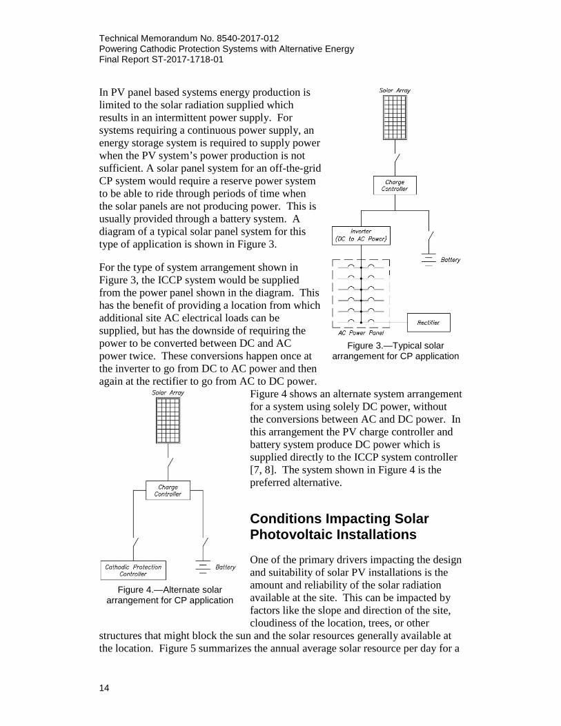
In PV panel based systems energy production is limited to the solar radiation supplied which results in an intermittent power supply. For systems requiring a continuous power supply, an energy storage system is required to supply power when the PV system’s power production is not sufficient. A solar panel system for an off-the-grid CP system would require a reserve power system to be able to ride through periods of time when the solar panels are not producing power. This is usually provided through a battery system. A diagram of a typical solar panel system for this type of application is shown in Figure 3. For the type of system arrangement shown in Figure 3, the ICCP system would be supplied from the power panel shown in the diagram. This has the benefit of providing a location from which additional site AC electrical loads can be supplied, but has the downside of requiring the power to be converted between DC and AC power twice. These conversions happen once at the inverter to go from DC to AC power and then again at the rectifier to go from AC to DC power.
Figure 4 shows an alternate system arrangement for a system using solely DC power, without the conversions between AC and DC power. In this arrangement the PV charge controller and battery system produce DC power which is supplied directly to the ICCP system controller [7, 8]. The system shown in Figure 4 is the preferred alternative.
Figure 3.—Typical solar
arrangement for CP application
Figure 4.—Alternate solar
arrangement for CP application
Conditions Impacting Solar Photovoltaic Installations One of the primary drivers impacting the design and suitability of solar PV installations is the amount and reliability of the solar radiation available at the site. This can be impacted by factors like the slope and direction of the site, cloudiness of the location, trees, or other
structures that might block the sun and the solar resources generally available at the location. Figure 5 summarizes the annual average solar resource per day for a

Technical Memorandum No. 8540-2017-012 Powering Cathodic Protection Systems with Alternative Energy
Final Report ST-2017-1718-01
15
tilt = latitude collector at various locations around the United States (U.S.). This map does not include factors that might impact specific local sites. Another significant driver of the design of the solar array is the amount of cloud cover at the location of the solar panel system. Most of Reclamation’s water delivery and storage projects are located in the Western U.S., so the cloud cover available at two locations in the west was chosen for comparison purposes. The mean monthly cloudy days for Albuquerque, New Mexico (NM), is shown in Figure 6, while the mean monthly cloudy days for Seattle, Washington (WA), is shown in Figure 7. The total annual number of cloudy days in Albuquerque, NM is 87 days, while the total annual number of cloudy days in Seattle, WA is 226 days [9]. Clearly this difference would have a significant impact on the design of the solar panel systems at these two locations. The following additional conditions can also impact the viability and cost of installing a solar panel system at a given location [10]:
• Solar resource • Available area • Local climate • Topography • Land use • Local regulations/land use policy or zoning • Environmental designations • Geotechnical conditions • Accessibility • Module soiling

Technical Memorandum No. 8540-2017-012 Powering Cathodic Protection Systems with Alternative Energy Final Report ST-2017-1718-01
16
Fi
gure
5.—
PV s
olar
reso
urce
s of
the
U.S
. [6]

Technical Memorandum No. 8540-2017-012 Powering Cathodic Protection Systems with Alternative Energy
Final Report ST-2017-1718-01
17
0
1
2
3
4
5
6
7
8
9
10
Jan Feb Mar Apr May Jun Jul Aug Sep Oct Nov Dec
Mean Monthly Cloudy DaysAlbuquerque, NM
Figure 6.—Mean monthly cloudy days for Albuquerque, NM [9]
0
5
10
15
20
25
Jan Feb Mar Apr May Jun Jul Aug Sep Oct Nov Dec
Mean Monthly Cloudy DaysSeattle, WA
Figure 7.—Mean monthly cloudy days for Seattle, WA [9]
A final important consideration is site security and the impact of vandalism on the equipment. While many of Reclamation’s water delivery and storage project sites are located in rural or other sparsely populated areas they are still vulnerable to vandalism. For example, at some locations the equipment is routinely shot at and

Technical Memorandum No. 8540-2017-012 Powering Cathodic Protection Systems with Alternative Energy Final Report ST-2017-1718-01
18
damaged. These factors can influence equipment redundancy requirements as well as siting and decisions impacting equipment visibility and security measures.
Sizing Solar Power Supplies When a solar panel system is used as a primary energy source both the PV system and the reserve power system (batteries) should be sized based on the electrical load, reserve power requirements, and conditions at the installation location. This design can also be impacted by considerations like the criticality of the components being powered by the solar panel system and how long the reserve power system needs to last. The simplest place to start when performing this evaluation is with the electrical load and the elements drawing power for immediate use. In the case of the system described in Figure 4, this would be the CP controller. For the purpose of this evaluation the assumed electrical load of the CP is approximately 300 W, the same electrical load used as the example in the Utility Supply section. The next step is to determine the reserve power requirement. This is based on the electrical load to be supplied and the duration that backup power is required for the electrical load. Due to the importance of maintaining power to the ICCP systems the backup power duration should be chosen to minimize the power outages that the system will experience. This should include consideration of the location where the system will be installed and the length of time between charging periods where the solar panels will be able to fully charge the batteries. In an example of a 300 watts (W) CP system located in Albuquerque, NM, the solar panel system would require a shorter backup power duration than one located in Seattle, WA, due to the reduced cloud cover that the location would experience. Given a mean of ten cloudy days per month in Albuquerque, a backup power for three days, or 72 hours, should provide a relatively reliable power source at this location. This duration along with the electrical load allows the battery to be sized according to the Institute of Electrical and Electronics Engineers (IEEE) 1013 [11] battery sizing criteria, including incorporating aging factors for the battery size. The down side of choosing a relatively high backup power duration is that it significantly increases the size of the batteries required. This also leads to higher output power requirements from the solar panels because they should be sized to fully recharge the battery within a single charging window. Once the electrical load and the electrical load associated with recharging the battery system have been determined. The National Renewable Energy Laboratory (NREL) has an online tool PVWatts® Calculator [12], which can be used to estimate the size of the solar panels.

Technical Memorandum No. 8540-2017-012 Powering Cathodic Protection Systems with Alternative Energy
Final Report ST-2017-1718-01
19
Components Solar Panels About 90 percent of the world’s PVs today are based on silicon. The efficiency of solar energy conversion to electricity depends on the purity of the silicon and the quality of its crystal structure. However, the manufacture of high purity silicon PV cells is expensive and must be balanced with other factors to achieve reasonable cost of the product [13]. In general, silicon-based PV cells can convert sunlight to energy at efficiencies between 8 and 20 percent and have a lifetime of no more than 30 years [10, 13]. A comparison of various types of solar cells can be found on the Energy Informative website [13].
Charge Controller
A charge controller supplies power to the battery to either maintain or recharge it while also supplying power to the electrical loads. The charge controller is also often used to regulate the voltage and charging current output from the controller to prevent supplying voltage or current outside of the battery’s charging limits. The input and output power range of the charge controller should be coordinated with the solar array design and batteries purchased. For instance GNB’s Sunlyte 12-5000x battery is a 6 cell 12 V battery and lists a charge voltage of between 2.28-2.38 V per cell with a 30 A maximum current [14]. For use with these batteries the charge controller would need to be rated to supply power within this voltage range. The output of most solar panels used for solar panel systems of this type, supplying over 300 W, will not maintain a voltage within the window of charge voltage that the battery requires. Failure to maintain this voltage, for instance by supplying voltage that is too high, can prematurely age the battery or cause other damage. Charge controllers are available in various shapes, sizes, features, and price ranges. They can be found as simple as 4.5 A controllers and can become as complex as 80 A controllers with a computer interface that can be used for system monitoring. For larger current requirements, multiple units can be wired in parallel. Generally, there are three types of charge controllers: 1 or 2 stage controllers that rely on relays or shunt transistors to control the voltage, the industry-standard 3 stage and/or pulse width modulation (PWM) controllers, and high-efficiency maximum power point tracking (MPPT) controllers [15].

Technical Memorandum No. 8540-2017-012 Powering Cathodic Protection Systems with Alternative Energy Final Report ST-2017-1718-01
20
Batteries
Batteries are rated in terms of Ah capacity, which is related to the amount of current a battery can supply for a specific time interval. Deep-cycle batteries designed for many charge/discharge cycles should be used for CP applications. A battery system must be able to supply the required output current before its replacement. The life cycle for lead-acid batteries varies depending on the quality of the battery purchased and how it is used, but temperature extremes can have a substantial effect on the longevity and output capacity of batteries.
Reliability The reliability of the solar panel system is impacted by both the reliability of the components that comprise the solar panel system and the reliability of conditions suitable to produce solar power. As discussed earlier, the availability of solar resources at the site must be evaluated to determine the duration of the backup power requirements.
Maintainability Solar panel systems in off-the-grid installations require routine maintenance to sustain operation. The solar panels and charge controllers will require periodic inspections to ensure that they are operating properly and have not been damaged. The battery systems require yearly testing and evaluation to monitor their health and current condition. Battery systems can fail relatively rapidly once they hit the point where aging accelerates. In addition, special maintenance activities may be required based on the weather conditions. These include periodically checking the arrays for things like snow or dust accumulation after weather events.
Relative Cost Installation The equipment costs are based on purchasing a 5 kW solar panel array and a battery backup system to supply an ICCP system. The cost evaluation doesn’t include the cost of the ICCP system components. This is intended for informational purposes only and does not include a detailed list of all components required for an installation of this type.
Electric load: 300 W Solar panel array rating: 5 kW
• For this example a 5 kW solar array is used. This array uses 16 LG

Technical Memorandum No. 8540-2017-012 Powering Cathodic Protection Systems with Alternative Energy
Final Report ST-2017-1718-01
21
NeON® 2, 33 W solar panels. Solar panel system purchase price: $359.99 [16] x 16 panels Total cost: $5,759.84
Battery system: 600 ampere-hour (Ah), 48 V
• This is based on a rough battery sizing estimate using a 300 W load at 48 VDC for approximately 72 hours with a 20 percent aging factor. It should be noted that actual battery sizing calculations should be done in accordance with the appropriate IEEE standard.
• For this example four GNB Industrial Power Absolyte® GP Model 6-90G11, 12 V, valve regulated lead acid batteries are used.
Battery purchase price: $2,027.03 [17] x 4 6-90G11 batteries Total cost: $8,011.96
Charge controller:
• Suitable for recharging battery from a solar panel system. • For this example a Morningstar Tristar MPPT 600 V 60 A charge
controller is used. Charge controller purchase price: $1,599.00 [18] x 2 Morningstar Tristar MPPT 600 V 60 A charge controllers Total cost: $3,198.00
Power distribution components: • Miscellaneous circuit breakers, electrical disconnects, etc. Purchase price: $1,000.00
Battery and inverter enclosure: National Electrical Manufacturers Association (NEMA) 250 type 3R enclosure
• Enclosure with internal racking system and cooling system. Enclosure purchase price: $5,000.00
Miscellaneous Components:
• Include cable, conduit, battery connectors, grounding components, etc. Miscellaneous components purchase price: $2,000.00
Labor
Labor cost: $3,500
Total: $28,500
Operation
Solar panel systems do not include consumable fuel sources or yearly utility fees. Costs for labor and maintaining the system are not included in this evaluation.

Technical Memorandum No. 8540-2017-012 Powering Cathodic Protection Systems with Alternative Energy Final Report ST-2017-1718-01
22
Standards for Solar Panel Systems and Specific Batteries Underwriters Laboratories Inc. Standards UL 1703-2002.–Standard for Flat-Plate Photovoltaic Modules and Panels
International Electrochemical Commission Standards IEC 61215-2005.–Crystalline Silicon Terrestrial Photovoltaic (PV) Modules – Design Qualification and Type Approval IEC 61646-2008.–Thin-film Terrestrial Photovoltaic Modules – Design Qualification and Type Approval
The Institute of Electrical and Electronics Engineers Standards IEEE 1526-2003.–Recommended Practice for Testing the Performance of Stand-Alone Photovoltaic Systems IEEE 1361-2003. –Guide for Selection, Charging, Test and Evaluation of Lead-Acid Batteries Used in Stand-Alone Photovoltaic Systems IEEE 1562-2007.–Guide for Array and Battery Sizing in Stand-Alone Photovoltaic Systems IEEE 937-2007. –Recommended Practice for Installation and Maintenance of Lead-Acid Batteries for Photovoltaic Systems IEEE 1013-2007.–Recommended Practice for Sizing Lead-Acid Batteries for Stand-Alone Photovoltaic Systems IEEE 1561-2007.–Guide for Optimizing the Performance and Life of Lead-Acid Batteries in Remote Hybrid Power Systems
Resources and Manufacturers Invensun produces solar panels ranging between 5 W and 300 W. They use a combination of grade A solar cells and a silicon nitride (SiN) coating to ensure that the solar panels are efficient and long-lasting. [19]. Morningstar provides solar controllers and inverters [20]. Evergreen Solar manufactures solar panels using “the string ribbon technology” [21].

Technical Memorandum No. 8540-2017-012 Powering Cathodic Protection Systems with Alternative Energy
Final Report ST-2017-1718-01
23
Ameresco Solar manufactures solar panels, batteries, controllers, inverters, mounting, enclosures, pre-wired backplates, and wiring and cables. It also offers a variety of pre-packed off-grid solar kits to meet a range of power needs [22]. SolarRay.com installs solar-powered CP systems across Wyoming, Utah, and Colorado jointly with United Contracting. Figures 8a and 8b show two of their operational systems in Utah and Colorado, respectively [23].
(a) (b)
Figure 8.—CP system installed for Chevron Oil with (a) 245 W modules, batteries, and charge controllers in Utah, and
(b) 20 A output in Colorado, reproduced from [23]
Figure 9.—Sunpole solar panel system, reproduced from (Farwest Corrosion Control Company,
n.d.)

Technical Memorandum No. 8540-2017-012 Powering Cathodic Protection Systems with Alternative Energy Final Report ST-2017-1718-01
24
Farwest Corrosion Control Company offers the Sunpole solar panel system (see Figure 9). This is up to a 24 V, 2 A preassembled pole-mounted system designed to provide 100% of daytime current during sunlight hours with a 50% cut at night [24]. Solarcom France offers solar micro-stations designed to power 12 V / 24 V or 48V low power loads [25]. Solaire Powering Systems manufacture solar panel arrays that can provide controllable 50 V and 50 A power [26]. OkSolar offers a variety of CP solutions using remote off-grid solar panel systems [27]. Absolyte® GP Batteries sells large valve-regulated lead-acid batteries [17]. Sunlyte® Bloc Batteries claim a “deep-cycle capability, long life, and low self-discharge rate” [28]. Sonnenschein® Solar Batteries are especially suited for small to mid - range power systems [29].
Fossil Fuel Combustion Engine Generator Supply System Arrangement Fossil fuel combustion engine generators generate power through combustion of fossil fuels and are commercially available in a variety of different arrangements, electrical ratings, and fuel options. Choosing a specific generator for an application is based on a variety of factors like availability of fuel sources and size of the electrical load the generator is supplying. When used in an off-the-grid application, like the ICCP system application, for a relatively small electrical load the generator is often used in combination with a reserve power system, like batteries, to reduce run time on the generator by charging the batteries. This prevents the generator from having to run continuously. A typical arrangement for these types of systems is shown in Figure 10.

Technical Memorandum No. 8540-2017-012 Powering Cathodic Protection Systems with Alternative Energy
Final Report ST-2017-1718-01
25
Figure 10.—Typical generator arrangement for CP applications
Similar to solar panel systems, generators should be sized for the electrical load that they are supplying and accommodate recharging the battery within the generator’s rated output. This can be complicated when motors, or other electrical loads that experience a current spike on start-up, are connected to the electrical distribution system. In those cases, the chosen equipment rating needs to accommodate supporting those loads without allowing too high of a voltage drop. The arrangement shown in Figure 10 for the ICCP system does not include any loads with high current spikes on start-up, so this issue does not need to be accounted for and a relatively straight forward generator sizing evaluation can be performed. Generator electrical ratings have two parts:
• the rated maximum real power output, often expressed in watts, and • the rated power factor.
The generator should have an appropriate power factor to be able to start and run the electrical loads it is connected to. The power factor rating is not as important for generators that are running static (non-rotating) loads. Many locales require generators to have environmental permitting, particularly regarding emissions, depending on the size of the generator, functionality, and variety of fuel. These restrictions should be considered when selecting a generator.

Technical Memorandum No. 8540-2017-012 Powering Cathodic Protection Systems with Alternative Energy Final Report ST-2017-1718-01
26
Fuel Types Various types of fossil fuels can be used in generators, including: diesel, propane, gasoline, and natural gas. Gasoline is frequently used by small generators and natural gas is common in larger generators. However, small gasoline generators typically require frequent tank refilling and natural gas generators require access to a natural gas line, so these systems are rarely used by Reclamation for continuous service in remote locations where the water delivery CP systems are located. Generators using diesel and propane are the most common in Reclamation facilities, however due to the remoteness of the CP rectifier locations this can present problem with supply and inspection. Propane tanks can supply generators rated up to 200 kW, and are often supplied using propane tanks or cylinders. Diesel generators are available at higher power ratings than propane generators and use liquid fuel stored on-site in tanks. The sizing of the fuel system is dependent on the fuel consumption of the generator and the amount of time needed for operation between refueling. In remote locations, several days or weeks of fuel may be supplied to limit the number of required refueling trips. Sizing fuel systems for long periods between refueling trips can significantly increase the size of the fuel tank or other fuel storage systems. The differences in delivery methods can lead to preferences between fuel types at some locations. The propane generators can be favored over other generator fuel types for remote systems of the size used for the CP systems. This is due to a general availability of propane in rural areas and because the delivery vehicles for propane cylinders are often smaller trucks and relatively maneuverable. There are different national codes and local permitting requirements that can apply to generators with different uses and fuel sources. Permitting requirements also vary between fuel types based on fuel emissions. Since propane operates with less emissions than diesel, it is preferred in more stringent states like California. As permitting requirements vary by location this should be investigated with the proper permitting authority early on in the project planning stages. The fuel choice can also affect some security considerations for the site with the generators. Diesel fuel can be easier to steal from tanks than propane, however propane is more combustible and is easier to blow up when vandals shoot at it.
Reliability Fossil fuel generators have a fuel source that can be highly reliable and, unlike wind and solar, is not dependent on the climate or other outside factors in the availability of its fuel source. The downside with these generators is that they

Technical Memorandum No. 8540-2017-012 Powering Cathodic Protection Systems with Alternative Energy
Final Report ST-2017-1718-01
27
have many moving parts and components and can have relatively high maintenance requirements. These generators require routine maintenance and can quickly become unreliable when not adequately maintained. In addition, the fuel supply may have additional needs according to climate conditions. Items like fuel additives, heaters, or other equipment may be required to allow proper operation of the generator.
Maintainability These generators require a relatively high level of staff interface and effort. This is required both for the routine fuel deliveries to the remote sites and for the relatively high levels of maintenance that these generators and fuel systems require. Fuel deliveries can become more challenging during adverse weather conditions, like snow, which can impact the reliability of the power source if the fuel cannot be delivered.
Relative Cost Installation The equipment costs are based on purchasing an 8 kW propane generator and a battery backup system to supply an ICCP system, the cost evaluation does not include the cost of the ICCP system components. This is intended for informational purposes only and does not include a detailed list of all components required for an installation of this type.
Electric load: 300 W Generator rating: 8 kW
• For this example an 8 kW Briggs & Stratton Standby Generator System, which operates by using liquid propane, is used. This generator includes an enclosure for outdoor installation.
Generator purchase price: $2,184.00 [30]
Battery system: 430 Ah, 48 V • This is based on a rough battery sizing estimate using a 300 W load at
48 VDC for approximately 48 hours with a 20 percent aging factor. It should be noted that actual battery sizing calculations should be done in accordance with the appropriate IEEE standard.
• For this example four GNB Industrial Power Absolyte® GP Model 6-50G13, 12 volt, valve regulated lead-acid batteries are used.
Battery purchase price: $1,746.20 [17] x 4 6-50G13 batteries
Hybrid inverter / charger:

Technical Memorandum No. 8540-2017-012 Powering Cathodic Protection Systems with Alternative Energy Final Report ST-2017-1718-01
28
• Suitable for off-grid applications, intended for AC input from the generator. Includes an interface for automatic generator start.
• For this example a 6800 W Schneider Electric Conext XW+ hybrid inverter charger, a Schneider Electric Conext control panel and a Schneider Electric Conext Automatic Generator Start (AGS) module are used.
Hybrid inverter/charger purchase price: $3,629.80 [31] + $249.47 for the control panel [32] + $200.00 for AGS module [17].
Power panel, circuit breakers, and electrical disconnects:
• Miscellaneous power panels, circuit breakers, and electrical disconnects.
Purchase price: $1,000.00 Battery and inverter enclosure: NEMA 250 Type 3R Enclosure
• Enclosure with internal racking system and cooling system. Enclosure purchase price: $5,000.00
Miscellaneous Components:
• Include cable, conduit, battery connectors, grounding components, etc. Miscellaneous components purchase price: $2,000
Labor
Labor cost: $3,500 Total: $25,000
Operation
The operating costs calculated below are based on the fuel charges for operating the propane generator for a year. Costs for labor and maintaining the system are not included in this evaluation.
Generator rating: 8 kW • This generator has a liquid propane consumption of 0.97 gallons per
hour (gph) [30].
Battery discharge time: • The battery is sized to support approximately 48 hours of run time for
the ICCP system at maximum load [17].
Battery recharge time: • The battery rating developed in the installation cost estimate was
430 Ah at 48 V. The inverter rating is 6,800 W, with a maximum

Technical Memorandum No. 8540-2017-012 Powering Cathodic Protection Systems with Alternative Energy
Final Report ST-2017-1718-01
29
charge current of 140 A. It will take roughly 3.5 hours to recharge the battery when factoring in the continued current draw from the ICCP system during the recharge cycle [17, 32].
Total generator runtime (yearly):
• The total cycle, generator charging the battery and then the battery discharging, takes approximately 51.5 hours. Factoring the total hours in a year, 8,760 hours, the generator will run for approximately 595 hours a year. Based on the generator’s fuel consumption of 0.97 gph this indicates that the generator will use approximately 577 gallons a year [30].
Generator fuel cost (yearly):
• Using a price for propane of $2.169/gallon, from the U.S. Energy Information Administration Data on Petroleum and Other Liquids December 2017 data [33], and a yearly propane consumption of 577 gallons yields a rough cost of fuel of $1,252 a year. This cost does not factor in additional fees, like the propane delivery cost to remote locations, and will experience variations over time and for localities.
Standards for Generators National Electrical Manufacturer’s Association NEMA MG 1-2016: Motors and Generators
Resources and Manufacturers Major generator manufacturers include: Cummins Generators [34], Caterpillar Electric Power Generation [35], and Hyundai [36].
Thermoelectric Generator Supply System Arrangement Thermoelectric Generators (TEGs) run on fuel, like propane or natural gas, and convert heat energy directly to electrical energy by heating thermocouples in an internal burner. The heating creates small potentials across the thermocouple junction. These types of TEGs have three main components: heat source, thermopile, and cooling fins [37].

Technical Memorandum No. 8540-2017-012 Powering Cathodic Protection Systems with Alternative Energy Final Report ST-2017-1718-01
30
Typically, TEGs are rated based the amount of power produced. Generators with outputs of up to 48 V and 500 W can be purchased in conjunction with a variable power resistor to control the output of the TEG. These generators also require battery systems, fuel systems, and control systems to distribute fuel to the generators and coordinate the components. National codes and local permitting requirements for TEGs require evaluation similar to the use of fossil fuel combustion engine generators. The impact of emission regulations on the generators may be different in some locations than those that impact the fossil fuel combustion engine generators, but the codes and standards for these fuel types still apply.
Reliability Thermoelectric generator systems operate by the use of fossil fuels, like natural gas or propane, so the fuel source can be independent of the climate or other outside factors. It is a relatively complex system and requires fuel, but does not have many moving parts, meaning that there is no significant maintenance required other than annual cleaning [38]. A downside is that current commercially available systems appear to be relatively limited in the amount of power that an individual unit can produce. The largest advertised unit found during a review of one of the manufacturer’s product lines was listed as having a maximum power output of 550 W at 24 V [38]. If the product was paired with a battery system to power the CP system load, multiple units would be required.
Maintainability There are several challenges to these systems for maintainability. The first is due to the relatively small installed base for these types of generators in remote off-the-grid power generation applications. This small installed base would require additional time and planning for acquiring spare parts and training maintenance technicians. Another challenge is the need to provide routine deliveries of fuel to the site, which would require additional staff effort. These systems would also experience the same fuel system maintenance requirements as fossil fuel combustion generators.
Relative Cost Identifying a cost for deploying these systems across a project for ICCP systems is difficult due to the limited number of manufacturers currently making these

Technical Memorandum No. 8540-2017-012 Powering Cathodic Protection Systems with Alternative Energy
Final Report ST-2017-1718-01
31
products for off-grid remote power applications. The fuel usage indicated for the largest 550 W Gentherm Global Technologies generator is listed on the datasheet as 20.1 gallons of propane a day [38]. This is roughly equivalent to the propane usage as the 8 kW generator used in the Fossil Fuel Combustion Engine Generator Supply evaluation (see section above).
Resources and Manufacturers Farwest Corrosion Control Company offers TEGs that are designed for impressed current for CP systems requiring between 10 VA and 1.5 kVA [39]. Gentherm Global Power Technologies supplies solid state systems to provide DC power to CP systems that operate on propane, butane, and natural gas [40]. Kryotherm offers gas fuel TEGs that can run on natural gas, propane or propane-butane mixture combustion [41].
Wind Turbine Generator Supply System Arrangement Wind turbine generators provide a small turbine energy source option that does not require periodic refueling. These turbines operate due to the kinetic energy of the wind, and are a possible energy source if a sufficient and steady source of wind is available. While there is a wide variety of wind turbines available (from very small up to large turbines used in utility wind farm applications) the turbines required for an ICCP system would generally be below 20 kW. This is be due to the small size of the electric load for the ICCP system, 300 W, which would make it difficult to financially justify the use of a larger unit. Due to the intermittent nature of the wind, a battery system would be required to provide backup power to the system when no power can be produced by the turbine. The backup battery system would be similar to those required for the solar application, although the battery sizing would need adjustment to account for the reliability of wind at the site. Figure 11 shows a CP unit in Wyoming featuring both solar and wind power [23], while Figure 12 details an arrangement with a DC bus hybrid power system.

Technical Memorandum No. 8540-2017-012 Powering Cathodic Protection Systems with Alternative Energy Final Report ST-2017-1718-01
32
Figure 11.—A CP unit in Wyoming featuring both
solar and wind power, reproduced from [23]
Figure 12.—Typical DC-bus hybrid power system, reproduced from [42]
Conditions Impacting Wind Turbine Installations Many of the same considerations that impact solar installations impact wind turbine installations too. Except where solar installations are concerned with the availability of solar resources, wind turbines are concerned with the availability of wind resources. Figure 13 summarizes the annual average wind speed at various

Technical Memorandum No. 8540-2017-012 Powering Cathodic Protection Systems with Alternative Energy
Final Report ST-2017-1718-01
33
locations around the U.S. at a height of 80 m above grade [43]. Unfortunately, wind is significantly more variable than solar based on the elevation of the equipment above the ground. This can be seen when comparing Figure 13 to Figure 14, which shows the wind speed at a height of 30 m above grade. This variation in the wind based on the turbine elevation makes the height of the generator an important consideration. ICCP systems require small loads that would generally be paired with small turbines. This can put the wind turbines for ICCP systems on the low end of wind turbine elevation spectrum and impact their viability. The graphs shown in Figure 15 and Figure 16 from studies documented in a paper by Bowen, A. et al [44], provide preliminary power and coefficient of power (CP) curves for two small wind turbines. Cp is the electricity produced by the wind turbine divided by total energy available by the wind. As can be seen in the graphs, relatively significant levels of wind are required for much of the output from the turbines. Individual sites can also experience variability in wind levels, which is not accurately reflected on the wind maps shown in Figure 13 and Figure 14. There can be geographic obstructions, which disproportionally impact shorter wind turbines, as well as other factors that can cause variability in the levels of wind. Due to the visual impact of tall wind turbines it would be unlikely to have a wind turbine for an ICCP application higher than 50 feet from grade elevation, although specific sites may get approval for a taller installation. The following additional conditions can also impact the viability and cost of installing a wind turbine at a given location:
• Wind resource • Available area • Local climate • Topography • Land use • Local regulations/land use policy or zoning • Environmental designations • Geotechnical conditions • Accessibility
A final important consideration is site security and the impact of vandalism on the equipment. Similar to the solar panel systems, some locations are vulnerable to vandalism. Equipment is routinely shot at and can receive bullet damage. This has an influence on equipment redundancy requirements as well as locations and decisions impacting equipment visibility.

Technical Memorandum No. 8540-2017-012 Powering Cathodic Protection Systems with Alternative Energy Final Report ST-2017-1718-01
34
Fi
gure
13.
—Av
erag
e an
nual
win
d sp
eed
at 8
0 m
[43]

Technical Memorandum No. 8540-2017-012 Powering Cathodic Protection Systems with Alternative Energy
Final Report ST-2017-1718-01
35
Fi
gure
14.
—Av
erag
e an
nual
win
d sp
eed
at 3
0 m
[43]

Technical Memorandum No. 8540-2017-012 Powering Cathodic Protection Systems with Alternative Energy Final Report ST-2017-1718-01
36
Figure 15.—Preliminary power and CP curves for the Gaia-Wind 11 kW [44]
Figure 16.—Preliminary power and Cp curves for the ARE 442 [44]

Technical Memorandum No. 8540-2017-012 Powering Cathodic Protection Systems with Alternative Energy
Final Report ST-2017-1718-01
37
Reliability Wind is a highly variable energy source and prone to abrupt changes in strength and power output. Wind turbine systems can also be susceptible to disruption based on both short and long term climate events. The reliability of wind systems is also highly dependent on the specific placement and height of the turbine to meet the estimated wind resources at the site. In addition, the wind resources at a given site may experience yearly cyclical events with months that routinely experience low and high wind levels. A comparison in the “Long-Term Wind Power Variability” by Wan, Y.H. [45], on the month by month power production at a wind farm located in Lake Benton in Minnesota, shows the yield of power production during the summer months that was 64 percent of the power production during the winter months. There is also reason for concern that a wind turbine used in an energy capture installation with a battery bank may negatively impact the capacity of the wind turbine and battery system. Baring-Gould et al. [42] found that systems with weak or small battery loads can experience reduced system efficiency because of premature regulation by the charge controller and spilled energy when the battery bank appears full to the charge controller, while a surplus of energy remains. Furthermore, due to premature voltage regulation, the batteries do not become fully charged, leading to premature battery degradation.
Maintainability Wind turbines have a high number of moving parts and electronic components so they require a high level of routine maintenance. In addition, the battery systems used for wind applications require maintenance similar to the battery systems for solar applications.
Relative Cost Installation The equipment costs are based on purchasing an 11 kW wind turbine generator with a battery backup system to supply an ICCP system. The cost evaluation does not include the cost of the CP system components. This is intended for informational purposes only and does not include a detailed list of all components required for an installation of this type.
Electric load: 300 W Generator rating: 11 kW
• For this example a Gaia 133, 11 kW wind turbine is used. An
Technical Memorandum No. 8540-2017-012 Powering Cathodic Protection Systems with Alternative Energy Final Report ST-2017-1718-01
38
exchange rate of 1 British pound to 1.34 U.S. dollars is used to convert the purchase price from the source document.
Wind turbine purchase price: $46,890.00 [46].
Battery system: 600 Ah, 48 V • This is based on a rough battery sizing estimate using a 300 W load at
48 VDC for approximately 72 hours with a 20 percent aging factor. It should be noted that actual battery sizing calculations should be done in accordance with the appropriate IEEE standard.
• For this example, four GNB industrial power Absolyte® GP Model 6-90G11, 12 volt, valve regulated lead-acid batteries are used.
Battery purchase price: $2,002.99 [17] x 4 6-90G11 batteries
Charge controller: • Suitable for recharging battery from a wind turbine. • For this example a Morningstar Tristar MPPT 600 V, 60 A charge
controller is used. Charge controller purchase price: $1,599.00 [18] x 2 Morningstar Tristar MPPT 600 V, 60 A charge controllers.
Power distribution components: • Miscellaneous power panels, circuit breakers, and electrical
disconnects. Purchase price: $1,000.00
Battery and charger enclosure: NEMA 250 Type 3R Enclosure • Enclosure with internal racking system and cooling system. Enclosure purchase price: $5,000.00
Miscellaneous components: • Include cable, conduit, battery connectors, grounding components, etc. Miscellaneous components purchase price: $2,000
Labor Labor cost: $3,500
Total: $69,600
Operation
Wind turbines do not include consumable fuel sources or yearly utility fees. Costs for labor and maintaining the system are not included in this evaluation.

Technical Memorandum No. 8540-2017-012 Powering Cathodic Protection Systems with Alternative Energy
Final Report ST-2017-1718-01
39
Standards for Wind Turbines International Electrotechnical Commission (IEC) IEC 61400-2:2013.–Small Wind Turbines
Fuel Cell Supply System Arrangement Fuel cells are off grid technology under development. Fuel cells produce current electrochemically from a variety of fuels including: hydrogen, methane, propane, and gasoline. Fuel cell require minimal maintenance and boast pollution-free, high- operation. The Office of Energy Efficiency and Renewable Energy Fuel Cell Technologies Office lists the following types of fuel cells on their website [47]:
• polymer electrolyte membrane fuel cells • direct methanol fuel cells • alkaline fuel cells • phosphoric acid fuel cells • molten carbonate fuel cells • solid oxide fuel cells • reversible fuel cells.
Options currently exist for both polymer electrolyte membrane fuel cells and solid oxide fuel cells (SOFC) for off-grid remote applications. Diagrams of these two types of fuel cells are shown in Figure 17.

Technical Memorandum No. 8540-2017-012 Powering Cathodic Protection Systems with Alternative Energy Final Report ST-2017-1718-01
40
G (a) (b)
Figure 17.— Diagrams of (a) polymer electrolyte membrane fuel cells (PEM) and (b) solid oxide fuel cells (SOFC), reproduced from [47]
Reliability Reliability is a concern for fuel cells. Polymer electrolyte membrane (PEM) stationary fuel cells can experience major performance delay after 1,000 hours of operation [48]. Solid oxide stationary fuel cells have a longer lifetime than PEM fuel cells, although even their lifetime is relatively short. An International Energy Agency Technology Essentials report [49] compares the fuel cell lifetime for PEM fuel cells at 2,000 hours with a lifetime for SOFC at 6,000 hours.
Maintainability There are several challenges that these systems face for maintainability. The main challenge is due to the relatively small number of fuel cells currently installed in remote off-the-grid power generation applications. A small installed base means additional time and planning would be required for acquiring spare parts and training maintenance technicians.
Relative Cost Identifying a cost for deploying these systems across a project for ICCP operational requirements is difficult due to the limited number of manufacturers currently making fuel cells for off-grid remote power applications.

Technical Memorandum No. 8540-2017-012 Powering Cathodic Protection Systems with Alternative Energy
Final Report ST-2017-1718-01
41
Resources/Manufacturers for Fuel Cells Atrex Energy has developed a SOFC (see Figure 18) to produce DC voltage for CP. The fuel cell is manufactured with inexpensive materials and can operate over a variable power range and provide a constant power output. This device can withstand harsh weather, extreme temperatures, and shock and vibration conditions [50].
Figure 18.—Atrex Energy tubular SOFC technology, reproduced from [50]
Ballard Power Systems has a backup power systems line, the FCgen®-H2PM zero emissions fuel cell system that has been designed to integrate easily with existing power equipment [51]. Plug Power has the GENSURE® product line of stationary hydrogen fuel cell solutions meeting critical customer backup, grid-supplement and off-grid power needs [52]. Sunfire key technology is the Solid Oxide Power Core – a stack of high-temperature solid oxide cells. Operation gases are natural gas and liquid petroleum gas. These power generators have high efficiency and low maintenance costs [53].
Summary Table 2 summarizes the criteria for each of the energy sources with a brief evaluation. When evaluating these factors for each of the power supply options it is important to remember that many of these power sources are heavily impacted

Technical Memorandum No. 8540-2017-012 Powering Cathodic Protection Systems with Alternative Energy Final Report ST-2017-1718-01
42
by location and the specific conditions at the individual site where the system would be installed. At this time the primary option should generally be a utility supplied power source. When utility sources are in close proximity to the ICCP system they often provide an economical power source with high reliability and low cost of maintenance. It is only when the CP system location is farther from utility power and the power source becomes unavailable or un-economical that alternative power sources should be considered in lieu of utility supplied power. Of all the alternative energy sources investigated, solar power appears to provide the best fit as the primary alternative power source, although it can be dependent on the site having good solar resources. The higher variability of wind power with low wind turbine elevations and the desire to minimize visual impact makes it less desirable in locations with good solar resources. All of the other three sources, TEGs, fossil fuel combustion generators, and fuel cells require significant staff involvement on an ongoing basis at the sites.

Technical Memorandum No. 8540-2017-012 Powering Cathodic Protection Systems with Alternative Energy
Final Report ST-2017-1718-01
43
Table 1.—Power Source Summary Power Sources
Utility Supply Solar Power Supply Fossil Fuel Combustion Engine Generator Supply
TEG Supply Wind-Driven Generator Supply
Fuel Cell Supply
Ease of Use High High Medium Low Medium Low Reliability High Medium Medium Medium Low Low
Maintainability Easy Medium Difficult Difficult Medium Difficult
Cost Low cost where power is available
Medium installation cost Low operating cost
Medium installation cost High operating cost
Low installation cost High operating cost
Medium installation cost Low operating cost
High installation cost High operating cost
Best Fit Where utility power is available in proximity to site.
Where there are good solar resources and few cloudy days.
Where there are poor solar resources and support for significant fuel deliveries.
Where there are poor solar resources and support for fuel deliveries.
Probably best fit as a secondary power source.
Where there is support for high staff involvement at facility


Technical Memorandum No. 8540-2017-012 Powering Cathodic Protection Systems with Alternative Energy
Final Report ST-2017-1718-01
45
References [1] National Association of Corrosion Engineers. 2006. CP2 Cathodic
Protection Course Manual. [2] Janowski M., and A. Wantuch. 2016. ICCP Cathodic Protection of Tanks
with Photovoltaic Power Supply. E3S Web of Conferences, vol. 10, no. 00029.
[3] Department of Natural Resources Underground Storage Tank Management
Program. 2003. Guidelines for the Evaluation of Underground Storage Tank Cathodic Protection Systems.
[4] Pacific Gas and Electric Company. 2016. Pacific Gas and Electric
Company 2015 Annual Reliability Report. [5] Black Hills Energy. Energy Schedule of Rates for Electric Service,
Accessed July 2017 from https://www.blackhillsenergy.com/ sites/default/files/bhe-coe-rates-tariff.pdf.
[6] U.S. Department of Energy. 2016. 2015 Renewable Energy Data Book. [7] Mosaieb, M.F.H., and K. Monfaredi. 2014. Novel Cathodic Protection
Systems Based on Photovoltaic Cells. Transaction on Electrical and Electronic Circuits and Systems, vol. 4, no. 20, pp. 117-123.
[8] Sollatek. Cathodic Protection Datasheet. Accessed May 2017 from
https://www.sollatek.com/wp-content/uploads/2014/07/Cathodic-protection-data-sheet.pdf.
[9] Western Regional Climate Center. Mean Monthly and Average Number of
Cloudy Days. Accessed August 2017 from https://wrcc.dri.edu/html files/westcomp.ovc.html.
[10] International Finance Corporation. 2015. Utility-Scale Solar Photovoltaic
Power Plants, A Project Developer's Guide. [11] Institute of Electrical and Electronics Engineers Standards. IEEE 1013 –
Recommended Practice for Sizing Lead-Acid Batteries for Stand-Alone Photovoltaic Systems, 2007.
[12] National Renewable Energy Laboratory. NREL’s PVWatts® Calculator.
Accessed September 2017 from http://pvwatts.nrel.gov/.

Technical Memorandum No. 8540-2017-012 Powering Cathodic Protection Systems with Alternative Energy Final Report ST-2017-1718-01
46
[13] Energy Informative. Solar Panel Types. Accessed May 2017 from http://energyinformative.org/best-solar-panel-monocrystalline-polycrystalline-thin-film/.
[14] GNB Industrial Power. Sunlyte 12-5000x Datasheet. Accessed
September 2017 from https://www.exide.com/sites/default/files/2017-01/Sunlyte%2012-5000X%20Specs.pdf.
[15] Northern Arizona Wind and Sun. Solar Charge Controller Basics.
Accessed May 2017 from https://www.solar-electric.com/solar-charge-controller-basics.html/.
[16] SolarPanelStore.com. Accessed September 2017 from http://www.solar
panelstore.com/solar-power/large-solarpanels/lg_solar_panel/lg_solar _neon2_330.html?_vsrefdom=adwords&gclid=EAIaIQobChMIko6ovZyn1gIVlISzCh0_7ADREAkYBCABEgLciPD_BwE.
[17] Inverter Supply. Accessed September 2017 from https://www.inverter
supply.com/index.php?main_page=product_info&products_id=5494&gclid=EAIaIQobChMIwLjY2c2m1gIVSQaGCh0iogCJEAYYASABEgJu6_D_BwE.
[18] Ecodirect.com. Accessed September 2017 from http://www.ecodirect
.com/Morningstar-MPPT-600V-DB-600VDC-MPPT-Controller-p/morningstar-ts-mppt-600v-db.htm?gclid=EAIaIQobChMI1P2Hgcym 1gIVglqGCh0axw26EAkYAyABEgIu7vD_BwE.
[19] Invensun. Solar Panels for Heavy Duty & Hazardous Workplaces.
Accessed May 2017 from http://www.invensun.com/solar-panels/heavy-duty-and-hazardous.
[20] Morningstar Corp. MPPT Charge Controllers. Accessed May 2017 from
http://www.morningstarcorp.com/products/. [21] Evergreen Solar. Accessed May 2017 from https://evergreensolar.com/. [22] Ameresco Solar. Solar Power Cathodic Protection. Accessed May 2017
from http://www.amerescosolar.com/solar-power-cathodic-protection. [23] SolarRay.com. Cathodic Protection Systems. Accessed May 2017 from
http://www.solarray.com/Cathodic-Protection/Solar-Cathodic-Protection-Systems_T.php.

Technical Memorandum No. 8540-2017-012 Powering Cathodic Protection Systems with Alternative Energy
Final Report ST-2017-1718-01
47
[24] Farwest Corrosion Control Company. Accessed May 2017 from http://www.farwestcorrosion.com/solar-power-supplies-for-cathodic-protection.html.
[25] Solarcom France. Cathodic Protection. Accessed May 2017 from
http://www.solarcomfrance.com/protection-cathodique.html [26] Solaire Powering Systems. Solar Cathodic Protection Systems. Accessed
May 2017 from http://www.solar-systems.co.in/solar-cathodic-protection-systems.htm.
[27] OkSolar.com. Cathodic Protection. Accessed May 2017 from
https://www.oksolar.com/lion/Item/cathodic%20protection/cathodic-protection.
[28] GNB Industrial Power. Sunlyte. Accessed September 2017 from
http://www2.exide.com/au/en/product-solutions/network-power/product/sunlyte.aspx.
[29] GNB Industrial Power. Sonnenschein® Solar. Accessed September 2017
from http://www2.exide.com/as/en/product-solutions/network-power/product/sonnenschein-solar.aspx.
[30] Grainger Industrial Supply. Accessed May 2017 from
https://www.grainger.com/product/ BRIGGS-STRATTON-Air-Engine-Cooling-46C509#sku=10001406.
[31] Green Energy Kits. Accessed September 2017 from https://greenenergy
kits.com/products/schneider-electric-conext-xw-8-5-kw-230v-inverter-charger-48v-export-model?utm_medium=cpc&utm_source=googlepla& variant=42297099792.
[32] Green Energy Kits. Accessed August 2017 from https://greenenergykits
.com/products/schneider-electric-conext-system-control-panel-for-xw-and-sw-865-1050-01?utm_medium=cpc&utm_source=googlepla& variant=42499122384.
[33] U.S. Energy Information Administation. Petroleum & Other Liquids.
Accessed September 2017 from https://www.eia.gov/dnav/pet/hist/Leaf Handler.ashx?n=PET&s=M_EPLLPA_PRS_NUS_DPG&f=M.
[34] Cummins Generators. Cummins Generators. Accessed May 2017 from
https://power.cummins.com/generator-list.

Technical Memorandum No. 8540-2017-012 Powering Cathodic Protection Systems with Alternative Energy Final Report ST-2017-1718-01
48
[35] Caterpillar Power Systems. Electric Power Generation. Accessed May 2017 from http://www.cat.com/en_US/products/new/power-systems/electric-power-generation.html.
[36] Hyundai Power Equipment Canada. Accessed May 2017 from
http://www.hyundaipower.ca/. [37] Gentherm Global Power Technologies. 8550-SD Thermoelectric
Generator w/ Over Temperature Shutdown Operating Manual Accessed September 2017 from http://www.genthermglobalpower.com/sites/ default/files/product_files/05585%20rev9%20-%208550-SD%20 Manual%20GPT_0.pdf.
[38] Gentherm Global Power Technologies. Model 8550 Thermoelectric
Generators. Accessed September 2017 from http://www.gentherm globalpower.com/sites/default/files/product_files/67213_rev0_8550%20spec%20sheet_0.pdf.
[39] Farwest Corrosion Control Company. Accessed May 2017 from
http://www.farwestcorrosion.com/thermoelectric-generators-for-cathodic-protection-by-global-thermoelectric.html.
[40] Gentherm Global Power Technologies. Cathodic Protection Systems.
Accessed May 2017 from http://www.genthermglobalpower.com/ sites/default/files/pdfs/67199_D_rev1%20CP%20NACE%20GPT%20Intl%20Brochure%20Web_0.pdf.
[41] Kryotherm. Accessed May 2017 from
http://kryothermtec.com/thermoelectric-generators-operating-on-gas-fuel.html.
[42] Baring-Gould, E., C. Newcomb, D. Corbus and R. Kalidas. 2001. Field
Performance of Hybrid Power Systems. American Wind Energy Association Windpower 2001 Conference. Washington, D.C.
[43] National Renewable Energy Laboratory. Wind Maps. Accessed
September 2017 from https://www.nrel.gov/gis/wind.html. [44] Bowen, A., A. Huskey, H. Link, K. Sinclair, T. Forsyth, D. Jager, J. Van
Dam and J. Smith. 2009. Small Wind Turbine Testing Results from the National Renewable Energy Lab. American Wind Energy Association Windpower.

Technical Memorandum No. 8540-2017-012 Powering Cathodic Protection Systems with Alternative Energy
Final Report ST-2017-1718-01
49
[45] Wen, Y.H. 2012. Long Term Wind Power Variability. National Renewable Energy Laboratory.
[46] Natural Energy. Gaia 133 11kW. Accessed September 2017 from
http://www.naturalenergyuk.co.uk/gaia/. [47] Office of Energy Efficiency and Renewable Energy Fuel Cell
Technologies. Types of Fuel Cells Accessed September 2017 from https://energy.gov/eere/fuelcells/types-fuel-cells.
[48] Wang, Y., K. Chen, J. Mishler, S. Chan Cho and X. Cordobes Adroher.
2011. A Review of Polymer Electrolyte Membrane Fuel Cells: Technology, Applications, and Needs on Fundamental Research. Applied Energy, vol. 88, pp. 981-1007.
[49] International Energy Agency. 2007. Energy Technology Essentials - Fuel
Cells. [50] Atrex Energy. SOFC Products. Accessed May 2017 from
http://ftp.acumentrics.com/sofc-products-about-fuel-cells.htm. [51] Ballard Power Systems. Backup Power Systems. Accessed September
2017 from http://ballard.com/fuel-cell-solutions/fuel-cell-power-products/backup-power-systems.
[52] Plug Power Inc. GENSURE Fuel Cells. Accessed September 2017 from
http://www.plugpower.com/products/gensure/. [53] Sunfire. Off-Grid Power – Maximum Reliability. Accessed May 2017
from http://www.sunfire.de/en/applications/off-grid.


![cathodic protection in practise · 2 [CATHODIC PROTECTION/BM] CATHODIC PROTECTION P E FRANCIS 1 INTRODUCTION The first practical use of cathodic protection is generally credited to](https://img.pdfslide.us/doc/110x75/5ace93c87f8b9ae2138b87e4/cathodic-protection-in-cathodic-protectionbm-cathodic-protection-p-e-francis.jpg)