Embed Size (px)
Citation preview
CHAPTER 33Enabling Technologies
In addition to energy generators that have been presented previously inthe literature (Beeby et al., 2006; Cook-Chennault et al., 2008; Pauloand Gaspar, 2010; Romero et al., 2009), there are novel approaches thatencompasses chemical (e.g. direct glucose fuel cells), thermal, and nano-generators. An updated review of the latest research development forbiomedical applications is discussed. Thermal generators require a ther-mal gradient to operate. This makes them impractical for deep implantswhere thermal gradients can be as high as 0.2�C but when placed at theskin surface they can have temperature differences from 1�C to 5�C.For example, 1�C of temperature gradient can be enough to produce upto 100 μW of power on average, which should be enough for poweringa cardiac pacemaker. New advances in nanotechnology promises evensmaller devices for implantable applications. Nanowires made of zincoxide (a nontoxic piezoelectric material) can be manufactured into aflexible implantable material that can harness the veins pulsations insidethe body to power heart beat and blood pressure monitors (Yang et al.,2009). Biological fuel cells, or direct glucose fuel cells, using glucoserather than nitrogen can be a possibility. Nishizawa et al. (2005) pre-sented this approach fabricating a coin-sized biofuel cell that generatedup to 140 μW of power.
3.1 CHEMICAL ENERGY
Direct glucose fuel cells, also known as biofuel cells, can use glucose asa fuel. The main advantage is that when using blood glucose for energygeneration, it produces water as byproduct. A biofuel cell prototypecapable of producing up to 140 μW of power was presented byNishizawa et al. (2005). However, these types of biofuel cells (enzymatictype) are challenged by the short lifetimes, in the order of several weeks,and by inefficient fuel oxidation (Barton et al., 2004; Minteer et al.,2007). Biological batteries, using biological fluids, have also beenreported. Lee (2005) developed a low-cost paper laminated battery(dimensions of 60 mm3 30 mm) using copper and magnesium as theelectrodes and a chloride-doped filter paper. This battery is activated
when droplets of urine (or other acid fluid, even apple juice) interactswith the doped paper. This battery produced power as high as 1.5 mW,with a voltage of 1.5 V. As the battery can be manufactured and inte-grated with bioMEMS, the author suggests that applications involvingurine samples can routinely monitor patient’s physiological responses.Potential additional applications related to home-base health kits andbiosensors. Interestingly enough, this battery is actually found in themarket in Japan in AA and AAA size presentations1.
3.2 THERMAL ENERGY
Thermal energy generation is limited by the Carnot efficiency equation(see Eq. 1.4 in Chapter 1). Taking the body temperature as the Thigh
term at 37�C (310 K), and using outdoor temperatures of 27�C (300 K)and 20�C (293 K) for the Tlow term into Eq. (1.4) allows for efficienciesranging from 3.2% to 5.5%. Although theoretical numbers, they arequite low for efficient energy generation. Today, thermoelectric materi-als offer efficiencies on the order of 1% for temperature gradientsunder 20�C (Starner and Paradiso, 2004).
The human body radiates around 300 W of power as heat. If allbody heat could be used for energy generation with efficienciesbetween 3% and 5%, 9�17 W of power could be harvested. The extrac-tion of all body heat would require wearing a special suit that couldnot be comfortable to carry. Thus, using a smaller area for power gen-eration, about 5% of body (similar to the neck area), a maximum of0.4�0.8 W could be produced. Increasing the exposed area to includethe head from 0.6 to 1.0 W of electrical power could be recovered.Commercial devices have been using this technology in a number ofproducts. The Citizen TEG wristwatch is capable of producing up to13 μW/cm2 using a temperature difference of 1�C (Flipsen, 2005), whilethe Applied Digital Solution’s Thermo Life Generator can produce upto 60 μW/cm2 with a temperature gradient of 5�C (Paradiso andStarner, 2005). Researchers have also being able to show that a subcu-taneous temperature gradient of 0.3�1.7�C can generate more than70 μW of power (Watkins et al., 2005). This is about the same level asthe power requirements for some pacemakers. Mateu et al. (2007) pre-sented an investigation where an externally mounted thermoelectric
1http://www.theregister.co.uk/2007/09/04/nopopo/.
32 Powering Biomedical Devices
generator delivered 2 mW of power for a temperature difference of7�C (dimensions of 2.5 cm3 2.5 cm with an added heat sink).
3.3 KINETIC ENERGY
Harnessing daily activities such as walking for passive energy generationis a well-documented topic. For instance, backpacks, the footfall, theswinging of the legs have been studied and devices have been designed.Items vary from large devices to those that can be carried in a pocket.
Backpacks have been engineered for energy generation. Rome et al.(2005) employed the up-and-down movement of backpack loads togenerate energy. This backpack design was divided in two frames: avertical-moving structure where the load was placed and a fixed frameattached to the individual. A toothed rack on the moving frame wasconnected to a gear box on the fixed structure, which was attached toa DC generator. When the movable structure traveled 4.5 cm, the gen-erator could rotate up to 5,000 rpm due to the gear box. Power genera-tion up to 7.4 W was reported when carrying heavy loads (38 kg). Inaddition, the load peak force from the movable design decreased up to12% when compared to a fixed cargo. This decrease in the metaboliccost increases the efficiency of the overall energy generation process.
A study of backpack straps as locations for piezoelectric generatorswas undertaken by Feenstra et al. (2008). The tension force on thestraps, with the stacks placed in series, was mechanically amplified andconverted into compressive load. It was reported a power generationof 176 μW when walking on a treadmill with a 40 lb load, while themaximum power output is expected to be on the order of 400 μW.Although this number seems small, it also requires minimal backpackmodification, enough for sensing capabilities.
Li et al. (2008) presented a knee-mounted brace for biomechanicalenergy harvesting during walking. A gear train and a small permanentmagnet generator were fitted on a custom knee brace. This generatorwas designed to harness the energy from leg deceleration rather thanfor continuous generation, similar to the generative braking process ofhybrid cars. The gait process is divided into two stages: swing andstance. At the swing phase when the leg is moved forward, the bodyuses energy to decelerate the limb. This generator, when operatedunder the right conditions, was able to produce a power peak close to
33Enabling Technologies
20 W and an average power output of 4.86 0.8 W. This generativebreaking was reported to use less than 1 W of metabolic power to pro-duce 1 W of electrical power, while if used continuously more than2 W of body work are needed to generate only 1 W of usable power.
A piezoelectric generator for powering artificial organs harnessingthe footfall during gait was presented by Antaki et al. (1995). Thisgenerator consisted of two hydraulic cylinders placed in a shoe insolecontaining lead zirconate titanate (PZT) piezoelectric stacks. Thehydraulic cylinders had pulse amplifiers beneath the toes and heel regionfor transforming the low-frequency footfall into high-frequency pulses.A 1/17 scale prototype was evaluated producing 150�675 mW forwalking (5.76 2.2 mWkg/L) and 675�2,100 mW (23.66 11.6 mWkg/L)for simulated jogging, while up to 6.2 W could be expected from a 75 kgindividual.
The bending of the shoe has been studied as well. A flexible piezo-electric generator was developed by Kymissis et al. (1998). They haveintroduced the concept of parasitic power generation capturing theenergy that otherwise would be wasted or dissipated. For example, a68 kg individual walking at 1 Hz with a 5 cm vertical displacementrepresents 67 W of power employed (Starner and Paradiso, 2004).Trying to harvest all the energy would severely interfere with the gaitprocess but using the deformation that a sports shoe suffers (less than1 cm) seemed practical. Kymissis et al. (1998) presented two differentpiezoelectric designs to be compared against an electromagnetic gener-ator. The first configuration was made of a stack of polyvinylidine-fluoride (PVDF) sheets shaped similar to a shoe sole to be stressedunder bending (the outside layers were stretched while the inner layerswere compressed). This arrangement provided 660 V with an averagepower output of 1.1 mW. The second configuration was designed toharness the heel strike using a unimorph strip (steel spring bonded to aPZT piezoelectric material sheet). The steel was bent stressing the PZTwhen there was a heel strike, generating peak voltages up to 150 V andpower outputs up to 1.8 mW. The electromagnetic design was madefrom a lever-driven flashlight generator mounted in a shoe. A hingedplate attached to the flashlight lever exploited 3 cm of walking strokeproducing an average power output of 230 mW, although interferingwith the normal gait. The piezoelectric shoe generators were also usedas Radio-frequency identification (RFID) transmitters sending a 12-bit
34 Powering Biomedical Devices
serial ID at 310 MHz every 3�6 steps up to a 20 m distance. Laterwork described a power output of 1.3 mW for the PVDF stack and8.4 mW for two back-to-back unimorphs (Shenck and Paradiso, 2001).Similar work from this group used push buttons with piezoelectricmaterials. These push buttons (commercial piezoelectric strikers con-nected to amorphous-core transformers) produced 0.5 mJ of energy at3 V for transmitting 12-bit ID code over 30 m several times (Paradisoand Feldmeier, 2001).
Heartbeats have been ideated as well for devising generators usingpiezoelectric materials. A patent granted in 1969 to Wen H. Kodescribed one of the first attempts to harness heart motion for electricgeneration. This generator described by Professor Ko was a piezoelec-tric rectangular-shaped cantilever beam with an added weight at itsfree end. The structure when vibrating at a suitable frequency pro-duced a signal rectified by a voltage doubler. This design was intendedto power an electrical implant such as a cardiac pacemaker. This pie-zoelectric device was tested on a dog’s heart beating at 80 bpm produc-ing a 4 V output voltage on a 105 Ω load for 160 μW of power.Edward A. Schroeppel’s patent (1987) described a different approachwhen trying to harness the heart motion to power a cardiac pacemakercircuit. This patent described a piezoelectric strip inside a catheter forhuman heart insertion. When the heart is beating, it bends the catheterwhich stresses the piezoelectric strip generating an output signal.
The first commercial oscillating rotational generators originatedfrom wristwatch companies. The Japanese company Seiko presentedthe Automatic Generating System (AGS) in 1986. This self-windingmechanism was used on wristwatches under the Kinetic brand name.The design consisted of a rotating pendulum mass, a gear box train(ratio 1:100), and a small permanent magnet generator. Due to wristposition changes, one oscillation from the pendulum mass produced100 rotations on the generator. According to Paradiso and Starner(2005), 5�10 μW of power was estimated to be produced when wornand 1 mW could be obtained when forcibly shaken. Swiss companyETA later introduced the Autoquartz with a different approach. Thependulum mass wound a spring connected to a small generator using agear box train. Once the spring was fully wound, it unwound makingthe generator rotate at 5�15 krpm for a short time (50 ms), generatingmore than 15 V and 6 mA (90 mW) (Paradiso and Starner, 2005).
35Enabling Technologies
Researchers have also investigated commercial wristwatch genera-tors to determine if it is possible to use them for implantable biomedicalapplications. For example, Goto et al. (1998, 1999) exploited theSeiko’s generator for powering a circuit to pace the heart of a dog.The generator, when placed for a 30 min period on the right ventricu-lar wall of a dog’s heart beating at 200 bpm, was able to store 80 mJof energy in a capacitor. Another test using a charged capacitor wascapable of pacing a dog’s heart at 140 bpm for 60 min consuming420 mJ. The actual energy requirement of 210 mJ for 30 min was high-er than the energy produced in the same amount of time, 80 mJ. The13 μJ of energy produced was compared against a cardiac pacemakerrequiring only 5 μJ (2.5 V, 0.4 ms, and 500 Ω load). This showed thefeasibility of generating the power needed for the stimulation. Nolong-term studies were presented considering the possible effects of thegenerator on the heart wall. Later work from Gorge et al. (2001) triedto determine how much power could be generated using the Seiko’sgenerator taped to the chest of individuals working in an office envi-ronment. It was concluded that, over a period of 8 h, the power gener-ated varied from 0.2 to 2.1 μW, with a mean value of 0.5 μW. Thispower level was considered to be 10�100 times less than required forcharging a cardiac pacemaker battery.
Further studies employing the Seiko generator have also beenundertaken. The analysis performed by Sasaki et al. (2005) found thatif the right conditions are given to keep the rotations, this generatorcan produce up to 10 times more energy than from swinging motionalone. A swinging motion at 1 Hz was found to produce 15 μW, whileself-excited rotations were able to produce up to 170 μW at 2 Hz. Theconditions to maintain these rotations were described as
j_θjt50 .ω (3.1)
2c
Amaω, 1 (3.2)
where θ is the rotation angle, ω is the angular speed, c is the electro-magnetic damping, A is the amplitude of the external oscillation, m isthe pendulum mass, and a is the distance between the center of gravityand the axis of rotation. Another promising linear generator was alsopresented by this group. It was composed of a permanent magnet masssuspended by springs and surrounded by a 400-turn coil. Although thelinear generator had an overall volume of 500 cm3, it was reported
36 Powering Biomedical Devices
that it produced up to 90 mW when excited at its natural resonant fre-quency of 6 Hz with a vibration amplitude of 5.5 mm.
Wang et al. (2005a) have also improved upon the original Seikodesign. Their objective was to increase the power output density fromabout 7.5 to 50 mW/cm3. This group fabricated a miniature eight-polepermanent magnet generator using an imbricated-pole stator with asingle wire-wound coil to be driven at high speed. A prototype gener-ated 15 mW at 6,000 rpm (100 Hz) after rectification by a Schottky-diode bridge for a volume slightly larger than 1 cm3.
In addition to the rotational design from wristwatches, linear dis-placement generators, similar to the commercial shake-driven flashlights,have also been investigated for body motion. Duffy and Carroll (2004)described one such design situated inside a shoe sole. The generator wascomposed of two opposing magnets attached together inside a containerwith three wrapped coils, about 45 mm long and 13 mm in diameter.The shoe generator produced 8.5 mW when tested at a frequency of5 Hz. A second generator design consisting of a set of fixed magnets fac-ing a moving magnet with a coil in between was also tested. This setwas able to produce up to 230 μW of power at a frequency of 5 Hz.Further work (Duffy and Carroll, 2005) evaluated different rectificationcircuits: half- and full-wave designs versus doubler and quadrupler volt-age multipliers. The doubler was found to produce a higher voltage andpower output. A six-coil design with sliding magnets produced peak-to-peak voltages of 4 V (400 mVrms) when tested at 2 Hz. The voltagedoubler offered a rectified power output close to 1 mW when using a0.1 F double-layer capacitor; although up to 2 mW was expected. It wasassumed that this was due to the capacitor taking longer to charge.
Studies made by Niu and Chapman (2006) evaluated arm swinging,foot movement, and trunk displacement as potential locations forenergy harvesting. Their proposed design used a linear electromagneticgenerator tested on the mentioned body locations. An average poweroutput of 10 mW and an open-circuit peak voltage of 7 V werereported for the device placed on the arm. A backpack-situated genera-tor produced 50�80 mW with a peak voltage of 20 V (open circuit),while the power output for the harvester worn on a shoe was 80 mWfor an open-circuit peak voltage close to 27 V. Power was measuredafter rectification while charging a battery. It was reported that imped-ance matching would increase the power by a factor of 3.
37Enabling Technologies
Linear electromagnetic generators have also been optimized forenergy harvesting while walking, as performed by von Buren andTroster (2007). The generator consisted of an air-core tubular structurehaving a flexure bearing and a free-sliding magnet stack surroundedby coils. Energy harvesters having a volume of 0.25 cm3 were analyzedwith different quantities of magnets (6�9) and coils (6�10). The poweroutput varied according to the body location but on average 2�25 μWwas recorded. A comparison was offered with a lithium�ion batteryhaving an energy density of 0.3 Wh/cm3. The battery would bedepleted in a 4-year period if 2 μW is drawn, or its energy would becompletely consumed in 4 months if the power drain is 25 μW. Aprototype with a volume of 0.5 cm3 (15 mm long, 6 mm diameter) hav-ing 6 magnets and 5 coils was tested below the knee while walking foran average output power of 35 μW and a peak power of 1 mW (electri-cal efficiency of 66% on a 10 Ω load).
Another study employing a linear electromagnetic generator(55 mm long, 17 mm diameter) using a free-sliding magnet surroundedby coils was presented by Saha et al. (2008). Two different configura-tions using magnetic springs (magnets located at the ends to repel thefree-sliding magnet) were presented. A first configuration having fixedmagnets at the ends (top and bottom of the tubular structure) wasplaced in a backpack. It provided 0.3 mW when walking and 2.46 mWwhen slowly running. A second configuration with the top fixed mag-net removed produced 0.95 mW when walking and 2.46 mW whenslowly running. The second arrangement had a higher sliding magnetdisplacement for a 300% increase in power output while walking and32% increase while slowly running. The energy stored in a Li�MnO2
coin coil cell battery reached 3.5 J after 1 h of walking. The energygenerated exceeded the power consumption of 700 μW (2.5 J in 1 h)for a wearable system composed of a light sensor, microphone, acceler-ometer, microprocessor, and RF transceiver.
Impact forces have also been studied for energy harvesting using pie-zoelectric materials. For example, a linear impact-based generator wasproposed by Renaud et al. (2005) for harnessing limb motion. Thisdesign consisted on a free-sliding mass (750 mg) with piezoelectric canti-lever beams at the ends for 10 mm displacement. When the sliding-massimpacts the cantilever beams, they resonate generating energy for anestimated power output of 40 μW. Further work (Renaud et al., 2009)tested a prototype (25 cm3, 60 g sliding mass) that produced 47 μW
38 Powering Biomedical Devices
when turned over every second and generated 600 μW at 10 Hz for10 cm linear displacement amplitude. A similar approach was also pre-sented by Cavallier et al. (2005) but using tin balls and several PZT can-tilever beams in a circular package (2 mm high, 14 mm diameter). Inspite of the fact that the objective was to compare the efficiency of PZTcantilever beams versus stacks of PZT�Silicon�PZT, the study demon-strated the use of low frequencies to excite vibrations in structures athigher frequency without the need of frequency tuning. The evaluationof the prototype was performed using one element tested at a frequencyof 6 Hz generating 62 nW. The complete generator with all the elementswould generate around 0.5 μW.
Prosthetic knee implants is another area where piezoelectric genera-tion has been studied, as evaluated by Platt et al. (2005a,b). Piezoelectrictransduction benefits from the knee location because forces can be up tothree times higher than the body weight. A laboratory test was elabo-rated using three piezoelectric stacks (1 cm3 1 cm3 2 cm). The proto-type was capable of producing 850 μW of continuously regulated power(19% electrical efficiency, 20% electromechanical efficiency).
A muscle-powered piezoelectric generator was presented byLewandowski et al. (2007). The generator was devised to be positionedin series with a muscle tendon to use the muscle contraction for piezo-electric stack compression. Power generation would benefit more fromelectrically stimulated muscle rather than natural muscle contractions.Hence, individuals with extensive paralysis are preferable, as electri-cally stimulated muscle would not interfere with natural muscle move-ment or other activities. In addition, the power needed to electricallystimulate the muscles is minimal in comparison with the power that amuscle can generate when using this generator. The forearm muscle(brachiocardialis), the dorso-lateral muscle on the trunk (latissimusdorsi), and the calf muscle (gastrocnemius) are capable of forces of 50,100, and 250 N, respectively. These forces on a piezoelectric stack(5 mm3 5 mm cross-sectional area, 1 Hz, and 250 ms) can producepower outputs of 8 μW (2.5 cm long, at brachiocardialis), 54 μW (4 cmlong, at latissimus dorsi), and 690 μW (8 cm long, at gastrocnemius). APZT stack prototype (5 mm3 5 mm3 18 mm) produced up to 80 μWfor a 250 N force. Muscle, tendon, and bone attachments were notmentioned in this investigation.
Tashiro et al. (2002) developed a variable-capacitance-type electro-static generator for harnessing the ventricular wall motion of a dog’s heart
39Enabling Technologies
using a honeycomb structure. The motion of the left ventricular wall wasmeasured for testing a prototype resonating at 6 Hz. This prototype wasmade of stacked strips (50 layers, 20 cells per layer) of corrugated polyes-ter film with evaporated aluminum (50 mm3 30 mm3 30 μm) anda mass (780 g) on top. An accelerometer placed on a dog’s heart was usedto drive a test setup with the same motion. The power output fromthe generator driven with the replicated heart motion was employed topace the dog’s heart at 180 bpm for over 2 h. An average of 36 μW powerwas obtained while for the stimulation pulse 18 μW was required.
Mitcheson et al. (2004a) reported an electrostatic nonresonant pro-totype employing a variable-gap parallel-plate capacitor. For a pre-charge of 30 V producing 0.3 μJ per cycle, 250 V were generated. Thisarrangement followed the coulomb-force parametric-generator(CFPG) architecture (using the contact force to damp the movement)described in Mitcheson et al. (2004b) and was reported as suitable forlarge amplitudes and low frequencies. Energy is produced only whenthe inertial force is larger than the damping force. A capacitor plate(200 mm2) with a proof mass made of stacked silicon plates(10 mm3 11 mm3 0.4 mm) was fabricated for a maximum displace-ment of 450 μm. The final discharge of 250 V was produced by acapacitance change from 15 to 127 pF (11 pF parasitic capacitance).Other work from this group presented a modified version of thisparallel-plate capacitor. Energy of 120 nJ and voltages up to 220 Vwere reported per cycle (using 30 V of charging voltage), although upto 2.6 μJ per cycle could be obtained for an optimized device (80 μWof power at 30 Hz). It is expected that if using gold as the proof massmaterial, the power output could be increased up to 10 times.
Arakawa et al. (2004) used an electret-based approach to avoid theneed of precharging. An overlapped area capacitor using amorphousperfluoropolymer (CYTOP), as the electret, was presented. This elec-tret material choice presented a charge density up to 0.68 mC/m2 whichproduced 6 μW with a sinusoidal input oscillation of 1 mm at 10 Hz.Later work from this group was presented by Tsutsumino et al. (2006).They were able to reach a charge density as high as 1.37 mC/m2 usingcorona discharging on a 15 μm film with 1,000 V of average surfacevoltage. At 20 Hz and 2 mmp-p vibration amplitude (150 V sinusoidalpeak-to-peak waveform), 38 μW of power output was achieved. Whencompared against Teflon AF, CYTOP presents a surface charge den-sity, σ, about 33 larger. A 93 increase in power generation could be
40 Powering Biomedical Devices
expected as power output is proportional to σ2. The surface chargedensity was sustained for more than 100 days, and it was stable up toits glass transition temperature, B108�C. The capacitor plates con-sisted of rectangular areas (10 mm3 20 mm) covered with electrodes(1 mm wide, 30 μm gap) and separated by an air gap (100 μm). For aprototype having 200 μm wide electrodes (50 μm gaps) and oscillationsof 1 mmp-p at 20 Hz, 1 mW of power can be generated.
Boland et al. (2005) used fixed electret plates with liquid droplets inbetween, called a liquid electret power generator (LEPG). The electretplates were covered with Teflon, and the dielectric was made of liquiddroplets in addition to air. Polar liquids present high dielectric con-stants producing large capacitance changes when air is replaced bydroplets. When the generator vibrates, the liquid droplets change thecapacitance of this arrangement producing energy. The prototype wasreported to produce 0.11 μW of power at 60 Hz, although it could pro-duce up to 10 μW of power.
ZnO nanowires have also been suggested for energy generation (Liuet al., 2008; Wang, 2008; Wang et al., 2008). Gao et al. (2007) indicatedthat the use of flexible substrates would enable the use of piezoelectricnano arrays for bendable power sources in implantable biosensors. A sin-gle nanowire is known to generate 50 mV, thus arrays of nanowires couldproduce enough from energy harvesting. Such nano arrays have reportedpower densities of 100�200 μW/cm2 (Gao et al., 2007). Power densitiesclose to 83 nW/cm2 for nanowires stimulated by ultrasonic waves havealso been reported (Liu et al., 2008).
Energy generation has also used spherical geometries using electro-magnetic transduction. Two devices having 1.5�4 cm3 were presentedby Bowers and Arnold (2008). The devices were held in the hand anda pocket during walking and running tests. Electrical power as high as1.4 mW was reported. A planar rotational electromagnetic device waspresented by Romero et al. (2011). The effective volume of the genera-tor was reported as 2 cm3. The device was capable of producing up to427 μW of power while walking on a treadmill and up to 540 μWwhen running. This generator was evaluated at several body locationsand different walking and running speeds.
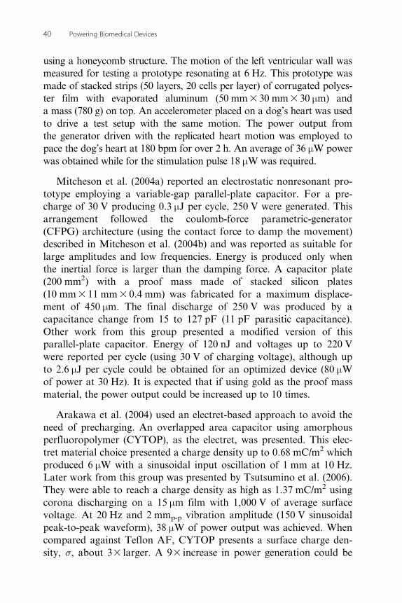
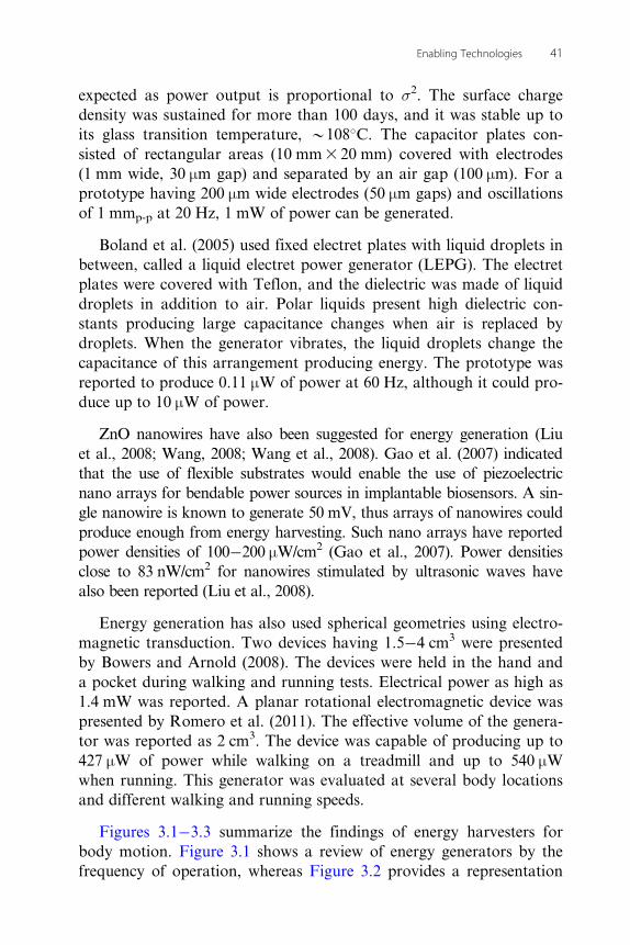
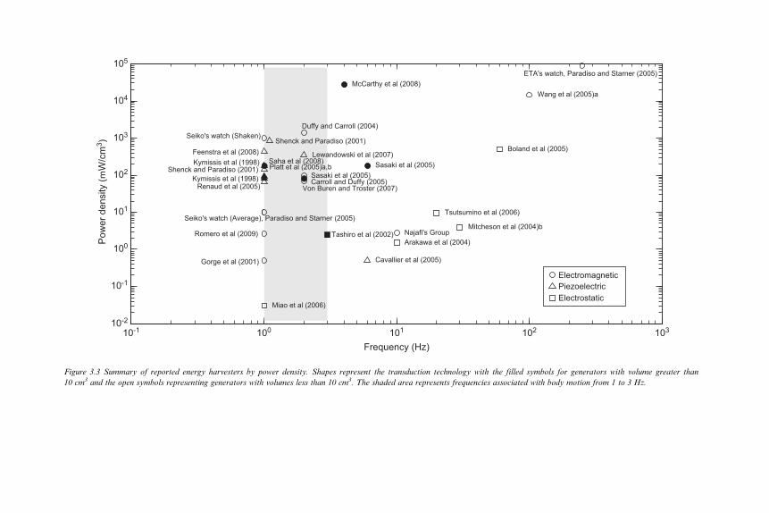
Figures 3.1�3.3 summarize the findings of energy harvesters forbody motion. Figure 3.1 shows a review of energy generators by thefrequency of operation, whereas Figure 3.2 provides a representation
41Enabling Technologies
10-2
10-1
10-1 100 101 102 103
100
101
102
103
104
105
106
107
Seiko's watch (Average), Paradiso and Starner (2005)
Seiko's watch (Shaken)
ETA's watch, Paradiso and Starner (2005)
Gorge et al (2001)
Duffy and Carroll 2004 Wang et al (2005)a
Sasaki et al (2005)
Niu and Chapman (2006)
Von Buren and Troster (2007)
Romero et al (2009)
Carroll and Duffy 2005
Rome et al (2005)
Sasaki et al (2005)
McCarthy et al (2008)
Li et al (2008)
Ko (1969)
Antaki et al (1995)
Kymissis et al (1998)
Shenck and Paradiso (2001)
Renaud et al (2005)
Cavallier et al (2005)
Platt et al (2005)a,b Lewandowski et al (2007)Feenstra et al (2008)
Kymissis et al 1998Shenck and Paradiso (2001)
Mitcheson et al (2004)b
Miao et al (2006)
Arakawa et al (2004)
Tsutsumino et al (2006)
Boland et al (2005)
Tashiro et al (2002)
ElectromagneticPiezoelectricElectrostatic
Frequency [Hz]
Pow
er (m
W)
Figure 3.1 Summary of energy harvesters by frequency of operation. Shapes represent the transduction technology with the filled symbols for generators with volume greater than10 cm3 and the open symbols representing generators with volumes less than 10 cm3. The shaded area represents frequencies associated with body motion from 1 to 3 Hz.
10-2
10-2 10-1 100 101 102 103
10-1
100
101
102
103
104
105
106
107
Seiko's watch (Average), Paradiso and Starner (2005)
Seiko's watch (Shaken)
Gorge et al (2001)
Duffy and Carroll (2004)
Carroll and Duffy (2005)
Rome et al (2005)
Sasaki et al (2005)
Niu and Chapman (2006)
Von Buren and Troster (2007)
Li et al (2008)
Romero et al (2009)
Saha et al (2008)
ETA's watch, Paradiso and Starner (2005)
Wang et al (2005)a
Sasaki et al (2005)McCarthy et al (2008)
Ko (1969)
Antaki et al (1995)
Kymissis et al (1998)Kymissis et al (1998)Shenck and Paradiso (2001)
Shenck and Paradiso (2001)
Renaud et al (2005)
Platt et al (2005)a,bLewandowski et al (2007)
Feenstra et al (2008)
Cavallier et al (2005)
Tashiro et al (2002)
Miao et al (2006)
Mitcheson et al (2004)b
Arakawa et al (2004)
Tsutsumino et al (2006)Boland et al (2005)
ElectromagneticPiezoelectricElectrostatic
Volume (cm3)
Pow
er (m
W)
Figure 3.2 Summary of energy harvesters by generator’s volume. Shapes represent the transduction technology with the filled symbols for generators with operating frequencies greaterthan 3 Hz and the open symbols representing generators operating at frequencies less than 3 Hz. The clear-shaded area represents volumes smaller than 1 cm3, while the darker area isfor volumes between 1 and 10 cm3.
10-2
10-1
10-1 100 101 102 103
100
101
102
103
104
105
Seiko's watch (Average), Paradiso and Starner (2005)
Seiko's watch (Shaken)
ETA's watch, Paradiso and Starner (2005)
Gorge et al (2001)
Duffy and Carroll (2004)
Carroll and Duffy (2005)
Wang et al (2005)a
Sasaki et al (2005)Sasaki et al (2005)
Von Buren and Troster (2007)
McCarthy et al (2008)
Romero et al (2009)
Saha et al (2008)
Najafi's Group
Kymissis et al (1998)
Kymissis et al (1998)Shenck and Paradiso (2001)
Shenck and Paradiso (2001)
Renaud et al (2005)
Cavallier et al (2005)
Platt et al (2005)a,b
Lewandowski et al (2007)Feenstra et al (2008)
Tashiro et al (2002)Mitcheson et al (2004)b
Miao et al (2006)
Arakawa et al (2004)
Tsutsumino et al (2006)
Boland et al (2005)
ElectromagneticPiezoelectricElectrostatic
Frequency (Hz)
Pow
er d
ensi
ty (m
W/c
m3 )
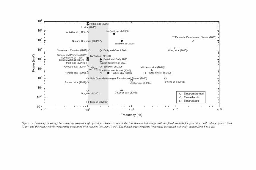
Figure 3.3 Summary of reported energy harvesters by power density. Shapes represent the transduction technology with the filled symbols for generators with volume greater than10 cm3 and the open symbols representing generators with volumes less than 10 cm3. The shaded area represents frequencies associated with body motion from 1 to 3 Hz.
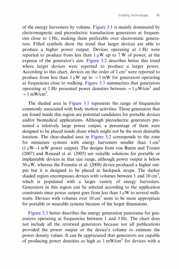
of the energy harvesters by volume. Figure 3.1 is mainly dominated byelectromagnetic and piezoelectric transduction generators at frequen-cies close to 1 Hz, making them preferable over electrostatic genera-tors. Filled symbols show the trend that larger devices are able toproduce a higher power output. Devices operating at 1 Hz werereported to produce from less than 1 μW up to 7 W of power, at theexpense of the generator’s size. Figure 3.2 describes better this trendwhere larger devices were reported to produce a larger power.According to this chart, devices on the order of 1 cm3 were reported toproduce from less than 1 μW up to B1 mW for generators operatingat frequencies close to walking. Figure 3.3 summarizes that generatorsoperating at 1 Hz presented power densities between B1 μW/cm3 andB1 mW/cm3.
The shaded area in Figure 3.1 represents the range of frequenciescommonly associated with body motion activities. Those generators thatare found inside this region are potential candidates for portable devicesand/or biomedical applications. Although piezoelectric generators pre-sented a relatively large power output, a percentage of them weredesigned to be placed inside shoes which might not be the most desirablelocation. The clear-shaded area in Figure 3.2 corresponds to the zonefor miniature systems with energy harvesters smaller than 1 cm3
(1 μW�1 mW power output). The designs from von Buren and Troster(2007) and Renaud et al. (2005) are suitable solutions for portable orimplantable devices in that size range, although power output is below50 μW, whereas the Feenstra et al. (2008) device produced a higher out-put but it is designed to be placed in backpack straps. The darkershaded region encompasses devices with volumes between 1 and 10 cm3,which is populated with a larger variety of energy harvesters.Generators in this region can be selected according to the applicationconstraints since power output goes from less than 1 μW to several milli-watts. Devices with volumes over 10 cm3 seem to be more appropriatefor portable or wearable systems because of the larger dimensions.
Figure 3.3 better describes the energy generation panorama for gen-erators operating at frequencies between 1 and 3 Hz. The chart doesnot include all the reviewed generators because not all publicationsprovided the power output or the device’s volume to estimate thepower density values. It can be appreciated that generators are capableof producing power densities as high as 1 mW/cm3 for devices with a
45Enabling Technologies
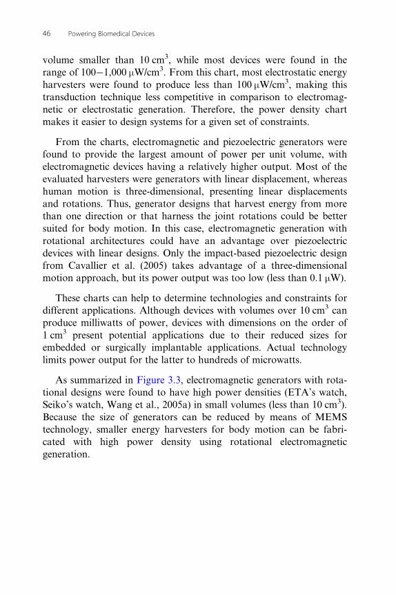
volume smaller than 10 cm3, while most devices were found in therange of 100�1,000 μW/cm3. From this chart, most electrostatic energyharvesters were found to produce less than 100 μW/cm3, making thistransduction technique less competitive in comparison to electromag-netic or electrostatic generation. Therefore, the power density chartmakes it easier to design systems for a given set of constraints.
From the charts, electromagnetic and piezoelectric generators werefound to provide the largest amount of power per unit volume, withelectromagnetic devices having a relatively higher output. Most of theevaluated harvesters were generators with linear displacement, whereashuman motion is three-dimensional, presenting linear displacementsand rotations. Thus, generator designs that harvest energy from morethan one direction or that harness the joint rotations could be bettersuited for body motion. In this case, electromagnetic generation withrotational architectures could have an advantage over piezoelectricdevices with linear designs. Only the impact-based piezoelectric designfrom Cavallier et al. (2005) takes advantage of a three-dimensionalmotion approach, but its power output was too low (less than 0.1 μW).
These charts can help to determine technologies and constraints fordifferent applications. Although devices with volumes over 10 cm3 canproduce milliwatts of power, devices with dimensions on the order of1 cm3 present potential applications due to their reduced sizes forembedded or surgically implantable applications. Actual technologylimits power output for the latter to hundreds of microwatts.
As summarized in Figure 3.3, electromagnetic generators with rota-tional designs were found to have high power densities (ETA’s watch,Seiko’s watch, Wang et al., 2005a) in small volumes (less than 10 cm3).Because the size of generators can be reduced by means of MEMStechnology, smaller energy harvesters for body motion can be fabri-cated with high power density using rotational electromagneticgeneration.
46 Powering Biomedical Devices