Embed Size (px)
Citation preview
VFD
To Keypad
CAT5 Cable
READY RUN FAULT
3 2 1 3 2 1
ONON
RA RB R CAVI
NPN
PNPPNP
ACIACI
READY RUN FAULT
3 2 1 3 2 1
ONON
RA RB R CAVI
NPN
PNPPNP
ACIACI
Remove Power Tap (if installed)
Connect CAT5 Cable
CAT5 Power Tap (REMOVE)
CAT5 Cable
To Keypad
WWW.BIGASSFANS.COM © 2018 DELTA T LLC ALL RIGHTS RESERVED. 1
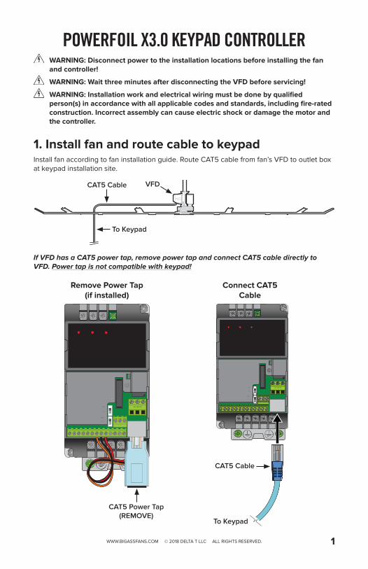
POWERFOIL X3.0 KEYPAD CONTROLLERWARNING: Disconnect power to the installation locations before installing the fan and controller!
WARNING: Wait three minutes after disconnecting the VFD before servicing!
WARNING: Installation work and electrical wiring must be done by qualified person(s) in accordance with all applicable codes and standards, including fire-rated construction. Incorrect assembly can cause electric shock or damage the motor and the controller.
1. Install fan and route cable to keypadInstall fan according to fan installation guide. Route CAT5 cable from fan’s VFD to outlet box at keypad installation site.
If VFD has a CAT5 power tap, remove power tap and connect CAT5 cable directly to VFD. Power tap is not compatible with keypad!
3.85” (98 mm)
7.25
” (18
4 m
m)
Depth: 1” (25 mm)
Outlet Box
Mounting Plate Keypad
Keypad Cover
Button Cover (optional)
6-32 x 1-1/4”
6-32 x 3/8”
CAT5 Cable
WWW.BIGASSFANS.COM © 2018 DELTA T LLC ALL RIGHTS RESERVED.2
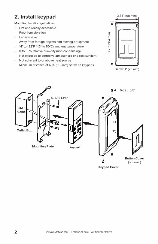
2. Install keypadMounting location guidelines:• Flat and readily accessible• Free from vibration• Fan is visible• Away from foreign objects and moving equipment• 14° to 122°F (-10° to 50°C) ambient temperature• 0 to 95% relative humidity (non-condensing)• Not exposed to corrosive atmosphere or direct sunlight• Not adjacent to or above heat source• Minimum distance of 6 in. (152 mm) between keypads
CAT5 Cable
Master Fan Keypad“LOC” illuminated
Slaved Fan Keypad“REM” illuminated
Slaved Fan Keypad“REM” illuminated
Slaved Fan Keypad“REM” illuminated
2-Conductor Shielded Cable with Drain Lead
Master Slave Disabled Master Slave Slave
WWW.BIGASSFANS.COM © 2018 DELTA T LLC ALL RIGHTS RESERVED. 3
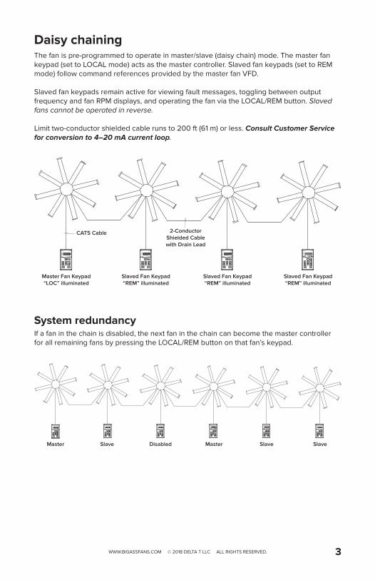
Daisy chainingThe fan is pre-programmed to operate in master/slave (daisy chain) mode. The master fan keypad (set to LOCAL mode) acts as the master controller. Slaved fan keypads (set to REM mode) follow command references provided by the master fan VFD.
Slaved fan keypads remain active for viewing fault messages, toggling between output frequency and fan RPM displays, and operating the fan via the LOCAL/REM button. Slaved fans cannot be operated in reverse.
Limit two-conductor shielded cable runs to 200 ft (61 m) or less. Consult Customer Service for conversion to 4–20 mA current loop.
System redundancyIf a fan in the chain is disabled, the next fan in the chain can become the master controller for all remaining fans by pressing the LOCAL/REM button on that fan’s keypad.
MI1
MI2
MI3
MI4
MI5
MI6
DCM
DCM
24V
ACM
AVI
ACI
10V
MCM
AFM
M01
RA
RB
RC
RS-4851: Reserved2: EV3: GND4: SG-5: SG+6: Reserved7: Reserved8: Reserved Digital Input
Digital Input
Digital Input
Digital Input
Digital Input
Digital Input
Digital Common
+24 VDC / 20 mA
ANL Common
ANL In 0–10 VDC / 47 kΩ
ANL In 4–20 mA / 250 Ω
+10 VDC / 3 mA
ANL Out; 0–10 VDC / 2 mA / 20 kΩ
Opto-Out Common
Opto-Out; Max 48 VDC / 50 mA
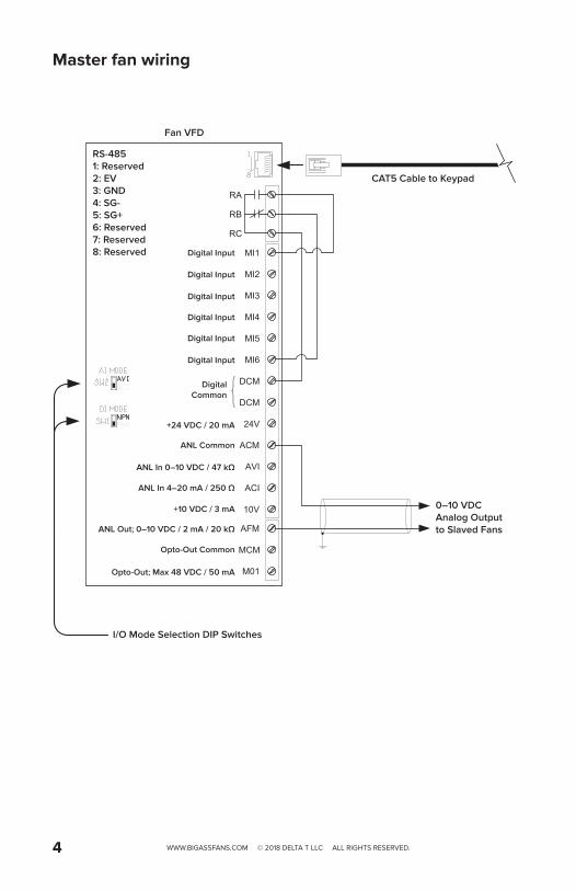
0–10 VDC Analog Output to Slaved Fans
I/O Mode Selection DIP Switches
CAT5 Cable to Keypad
Fan VFD
WWW.BIGASSFANS.COM © 2018 DELTA T LLC ALL RIGHTS RESERVED.4
Master fan wiring
MI1
MI2
MI3
MI4
MI5
MI6
DCM
DCM
24V
ACM
AVI
ACI
10V
MCM
AFM
M01
RA
RB
RC
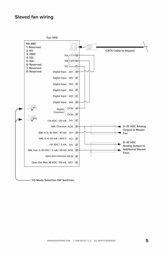
0–10 VDC Analog Output to Master Fan
0–10 VDC Analog Output to Additional Slaved Fans
I/O Mode Selection DIP Switches
RS-4851: Reserved2: EV3: GND4: SG-5: SG+6: Reserved7: Reserved8: Reserved Digital Input
Digital Input
Digital Input
Digital Input
Digital Input
Digital Input
Digital Common
+24 VDC / 20 mA
ANL Common
ANL In 0–10 VDC / 47 kΩ
ANL In 4–20 mA / 250 Ω
+10 VDC / 3 mA
ANL Out; 0–10 VDC / 2 mA / 20 kΩ
Opto-Out Common
Opto-Out; Max 48 VDC / 50 mA
CAT5 Cable to Keypad
Fan VFD
WWW.BIGASSFANS.COM © 2018 DELTA T LLC ALL RIGHTS RESERVED. 5
Slaved fan wiring
MI1
MI2
MI3
MI4
MI5
MI6
DCM
DCM
24V
ACM
AVI
ACI
10V
MCM
AFM
M01
RA
RB
RC
RS-4851: Reserved2: EV3: GND4: SG-5: SG+6: Reserved7: Reserved8: Reserved Digital Input
Digital Input
Digital Input
Digital Input
Digital Input
Digital Input
Digital Common
+24 VDC / 20 mA
ANL Common
ANL In 0–10 VDC / 47 kΩ
ANL In 4–20 mA / 250 Ω
+10 VDC / 3 mA
ANL Out; 0–10 VDC / 2 mA / 20 kΩ
Opto-Out Common
Opto-Out; Max 48 VDC / 50 mA
CAT5 Cable to Keypad
Fan VFD
FWD / STOP
REV / STOP
Required 0–10 VDC Analog Speed Reference
Optional 0–10 VDC Analog Speed Feedback
Optional Drive Fault Status Output 48 V @ 50 mA max.
WWW.BIGASSFANS.COM © 2018 DELTA T LLC ALL RIGHTS RESERVED.6
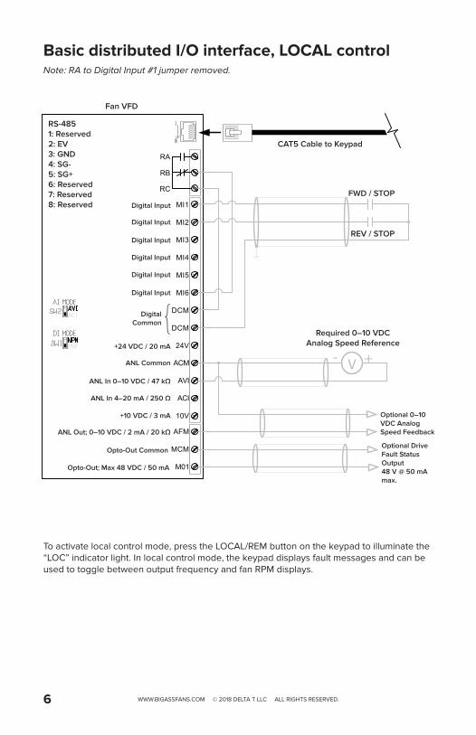
Basic distributed I/O interface, LOCAL controlNote: RA to Digital Input #1 jumper removed.
To activate local control mode, press the LOCAL/REM button on the keypad to illuminate the “LOC” indicator light. In local control mode, the keypad displays fault messages and can be used to toggle between output frequency and fan RPM displays.
V +-
MI1
MI2
MI3
MI4
MI5
MI6
DCM
DCM
24V
ACM
AVI
ACI
10V
MCM
AFM
M01
RA
RB
RC
RS-4851: Reserved2: EV3: GND4: SG-5: SG+6: Reserved7: Reserved8: Reserved Digital Input
Digital Input
Digital Input
Digital Input
Digital Input
Digital Input
Digital Common
+24 VDC / 20 mA
ANL Common
ANL In 0–10 VDC / 47 kΩ
ANL In 4–20 mA / 250 Ω
+10 VDC / 3 mA
ANL Out; 0–10 VDC / 2 mA / 20 kΩ
Opto-Out Common
Opto-Out; Max 48 VDC / 50 mA
CAT5 Cable to Keypad
Fan VFD
Required 0–10 VDC Analog Speed Reference
Optional 0–10 VDC Analog Speed Feedback
Optional Drive Fault Status Output 48 V @ 50 mA max.
I/O Mode Selection DIP Switches
FWD / STOP
REV / STOP
WWW.BIGASSFANS.COM © 2018 DELTA T LLC ALL RIGHTS RESERVED. 7
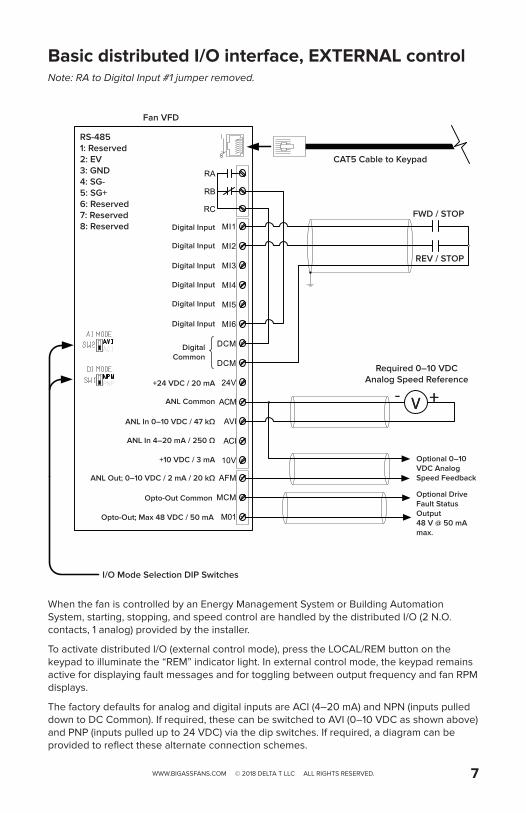
Basic distributed I/O interface, EXTERNAL controlNote: RA to Digital Input #1 jumper removed.
When the fan is controlled by an Energy Management System or Building Automation System, starting, stopping, and speed control are handled by the distributed I/O (2 N.O. contacts, 1 analog) provided by the installer.
To activate distributed I/O (external control mode), press the LOCAL/REM button on the keypad to illuminate the “REM” indicator light. In external control mode, the keypad remains active for displaying fault messages and for toggling between output frequency and fan RPM displays.
The factory defaults for analog and digital inputs are ACI (4–20 mA) and NPN (inputs pulled down to DC Common). If required, these can be switched to AVI (0–10 VDC as shown above) and PNP (inputs pulled up to 24 VDC) via the dip switches. If required, a diagram can be provided to reflect these alternate connection schemes.
MI1
MI2
MI3
MI4
MI5
MI6
DCM
DCM
24V
ACM
AVI
ACI
10V
MCM
AFM
M01
RA
RB
RC
RS-4851: Reserved2: EV3: GND4: SG-5: SG+6: Reserved7: Reserved8: Reserved Digital Input
Digital Input
Digital Input
Digital Input
Digital Input
Digital Input
Digital Common
+24 VDC / 20 mA
ANL Common
ANL In 0–10 VDC / 47 kΩ
ANL In 4–20 mA / 250 Ω
+10 VDC / 3 mA
ANL Out; 0–10 VDC / 2 mA / 20 kΩ
Opto-Out Common
Opto-Out; Max 48 VDC / 50 mA
Fan VFD
I/O Mode Selection DIP Switches
CAT5 Cable to Keypad
Thermostat, Timer, or Other Equipment Wall Contact
WWW.BIGASSFANS.COM © 2018 DELTA T LLC ALL RIGHTS RESERVED.8Rev. A
06/27/2018PX3-INST-223-ENG-01
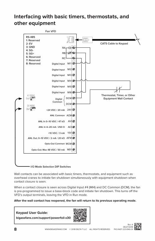
Interfacing with basic timers, thermostats, and other equipment
Wall contacts can be associated with basic timers, thermostats, and equipment such as overhead cranes to initiate fan shutdown simultaneously with equipment shutdown when contact closure is seen.
When a contact closure is seen across Digital Input #4 (MI4) and DC Common (DCM), the fan is pre-programmed to issue a base-block code and initiate fan shutdown. This turns off the VFD’s output terminals, leaving the VFD in Run mode.
After the wall contact has reopened, the fan will return to its previous operating mode.
Keypad User Guide:bigassfans.com/support/powerfoil-x30