Embed Size (px)
Citation preview
PowerFlex 750-Series AC Drives with TotalFORCE ControlCatalog Number 20G
Quick StartOriginal Instructions

Important User Information
Read this document and the documents listed in the additional resources section about installation, configuration, and operation of this equipment before you install, configure, operate, or maintain this product. Users are required to familiarize themselves with installation and wiring instructions in addition to requirements of all applicable codes, laws, and standards.
Activities including installation, adjustments, putting into service, use, assembly, disassembly, and maintenance are required to be carried out by suitably trained personnel in accordance with applicable code of practice.
If this equipment is used in a manner not specified by the manufacturer, the protection provided by the equipment may be impaired.
In no event will Rockwell Automation, Inc. be responsible or liable for indirect or consequential damages resulting from the use or application of this equipment.
The examples and diagrams in this manual are included solely for illustrative purposes. Because of the many variables and requirements associated with any particular installation, Rockwell Automation, Inc. cannot assume responsibility or liability for actual use based on the examples and diagrams.
No patent liability is assumed by Rockwell Automation, Inc. with respect to use of information, circuits, equipment, or software described in this manual.
Reproduction of the contents of this manual, in whole or in part, without written permission of Rockwell Automation, Inc., is prohibited.
Throughout this manual, when necessary, we use notes to make you aware of safety considerations.
Labels may also be on or inside the equipment to provide specific precautions.
WARNING: Identifies information about practices or circumstances that can cause an explosion in a hazardous environment, which may lead to personal injury or death, property damage, or economic loss.
ATTENTION: Identifies information about practices or circumstances that can lead to personal injury or death, property damage, or economic loss. Attentions help you identify a hazard, avoid a hazard, and recognize the consequence.
IMPORTANT Identifies information that is critical for successful application and understanding of the product.
SHOCK HAZARD: Labels may be on or inside the equipment, for example, a drive or motor, to alert people that dangerous voltage may be present.
BURN HAZARD: Labels may be on or inside the equipment, for example, a drive or motor, to alert people that surfaces may reach dangerous temperatures.
ARC FLASH HAZARD: Labels may be on or inside the equipment, for example, a motor control center, to alert people to potential Arc Flash. Arc Flash will cause severe injury or death. Wear proper Personal Protective Equipment (PPE). Follow ALL Regulatory requirements for safe work practices and for Personal Protective Equipment (PPE).

Table of Contents
Preface . . . . . . . . . . . . . . . . . . . . . . . . . . . . . . . . . . . . . . . . . . . . . . . . . . . . . . . . .5Introduction . . . . . . . . . . . . . . . . . . . . . . . . . . . . . . . . . . . . . . . . . . . . . . . . . . . 5Who Should Use This Manual . . . . . . . . . . . . . . . . . . . . . . . . . . . . . . . . . . 5Equipment . . . . . . . . . . . . . . . . . . . . . . . . . . . . . . . . . . . . . . . . . . . . . . . . . . . . 5
Supported Applications . . . . . . . . . . . . . . . . . . . . . . . . . . . . . . . . . . . . . 5Installation. . . . . . . . . . . . . . . . . . . . . . . . . . . . . . . . . . . . . . . . . . . . . . . . . 5
Additional Resources . . . . . . . . . . . . . . . . . . . . . . . . . . . . . . . . . . . . . . . . . . . 6
Step 1: Gather the Required InformationRecord Motor Nameplate and AC Power Data. . . . . . . . . . . . . . . . 9Record Velocity Reference and Start/Stop Sources . . . . . . . . . . . 11
Step 2: Validate the Drive InstallationVerify the Setting of the ENABLE and SAFETY Jumpers. . . . . 13Verify Power Source Ratings and Wiring Configurations . . . . . 14Verify Power Wiring. . . . . . . . . . . . . . . . . . . . . . . . . . . . . . . . . . . . . . . 15Verify Power Jumper Configuration. . . . . . . . . . . . . . . . . . . . . . . . . 15Verify I/O Wiring . . . . . . . . . . . . . . . . . . . . . . . . . . . . . . . . . . . . . . . . . 16
Step 3: Power Up, Configure the Modular Control ProfilesPreparation . . . . . . . . . . . . . . . . . . . . . . . . . . . . . . . . . . . . . . . . . . . . . . . . . . . 17Startup Using the HIM . . . . . . . . . . . . . . . . . . . . . . . . . . . . . . . . . . . . . . . . 17
HIM Navigation Keys . . . . . . . . . . . . . . . . . . . . . . . . . . . . . . . . . . . . . 18HIM Soft Keys . . . . . . . . . . . . . . . . . . . . . . . . . . . . . . . . . . . . . . . . . . . . 18HIM Single Function Keys . . . . . . . . . . . . . . . . . . . . . . . . . . . . . . . . . 19HIM Alarms and Faults . . . . . . . . . . . . . . . . . . . . . . . . . . . . . . . . . . . . 19Power the Drive . . . . . . . . . . . . . . . . . . . . . . . . . . . . . . . . . . . . . . . . . . . 21Configure the Motor Side Inverter. . . . . . . . . . . . . . . . . . . . . . . . . . 22Reset Device and Verify the Configurations. . . . . . . . . . . . . . . . . . 24Configure the Embedded EtherNet/IP Communication Adapter . . . . . . . . . . . . . . . . . . . . . . . . . . . . . . . . . . 25Set the Embedded Ethernet Adapter IP Address Switches . . . . . 27
Step 4: Configure the Line Side ConverterEnter Line Side Converter Settings. . . . . . . . . . . . . . . . . . . . . . . . . . 28
Step 5: Enter Motor Nameplate DataEnter Motor Nameplate Data . . . . . . . . . . . . . . . . . . . . . . . . . . . . . . 29Enter Motor Poles . . . . . . . . . . . . . . . . . . . . . . . . . . . . . . . . . . . . . . . . . 29Enter Motor Overload Hertz . . . . . . . . . . . . . . . . . . . . . . . . . . . . . . . 30
Step 6: Autotune the Motor Side Inverter ControlPerform the Direction Test. . . . . . . . . . . . . . . . . . . . . . . . . . . . . . . . . 31
Rockwell Automation Publication 750-QS100A-EN-P - July 2019 3
Table of Contents
Perform the Motor ID Test . . . . . . . . . . . . . . . . . . . . . . . . . . . . . . . . 31Configuration Complete . . . . . . . . . . . . . . . . . . . . . . . . . . . . . . . . . . . 33
Step 7: Set Up Velocity ReferenceDefault Reference Source. . . . . . . . . . . . . . . . . . . . . . . . . . . . . . . . . . . 34Door Mounted or Remote Mounted HIM . . . . . . . . . . . . . . . . . . 34Connections on 11-Series I/O Module - Cat. No. 20-750-11xxx-xxxx or 22-Series I/O Module - Cat. No. 20-750-22xxx-xxxx. . . . . . . . . . . . . . . . . . . . . . . . . . . . . . . . 34Embedded EtherNet/IP Interface . . . . . . . . . . . . . . . . . . . . . . . . . . . 35
Step 8: Set Up Start/StopDoor Mounted or Remote Mounted HIM . . . . . . . . . . . . . . . . . . 36Control on 11-Series I/O Module - Cat. No. 20-750-11xxx- xxxx or 22-Series I/O Module - Cat. No. 20-750-22xxx-xxxx . . . . . . . . . . . . . . . . . . . . . . . . . . . . . . . . . . . . 36Embedded EtherNet/IP Interface . . . . . . . . . . . . . . . . . . . . . . . . . . . 37
Step 9: Other SettingsAcceleration and Deceleration Times . . . . . . . . . . . . . . . . . . . . . . . 38Analog Outputs . . . . . . . . . . . . . . . . . . . . . . . . . . . . . . . . . . . . . . . . . . . 38Digital Outputs . . . . . . . . . . . . . . . . . . . . . . . . . . . . . . . . . . . . . . . . . . . 39
Step 10: Verify Drive OperationConfiguration Considerations . . . . . . . . . . . . . . . . . . . . . . . . . . . . . . 41
Appendix A: Reference InformationStatus Indicators. . . . . . . . . . . . . . . . . . . . . . . . . . . . . . . . . . . . . . . . . . . 43Setting Factory Defaults. . . . . . . . . . . . . . . . . . . . . . . . . . . . . . . . . . . . 44Reset Device . . . . . . . . . . . . . . . . . . . . . . . . . . . . . . . . . . . . . . . . . . . . . . 46Using Closed Loop Velocity Control. . . . . . . . . . . . . . . . . . . . . . . . 46Line Side Converter Settings . . . . . . . . . . . . . . . . . . . . . . . . . . . . . . . 49High Inertia Loads . . . . . . . . . . . . . . . . . . . . . . . . . . . . . . . . . . . . . . . . 50Disable the HIM Start Function . . . . . . . . . . . . . . . . . . . . . . . . . . . . 51Using the HIM CopyCat Function . . . . . . . . . . . . . . . . . . . . . . . . . 51
4 Rockwell Automation Publication 750-QS100A-EN-P - July 2019

Preface
Introduction
This Quick Start guide is designed to guide you through the 10 basic steps that are required to start up your PowerFlex® 755TL low harmonic, or PowerFlex 755TR regenerative stand-alone AC drives, for the first time for simple applications. This procedure uses the HIM to configure parameters. You may prefer to use Connected Components Workbench™ (version 10 or later) software and associated the PowerFlex 755T Wizards for this instead of the HIM.
Who Should Use This Manual
This manual is intended for qualified personnel.• You must understand the hazards that are associated with electromechanical equipment installations.• You must understand and follow all applicable local, national, and/or international electrical codes.• You must be able to program and operate Adjustable Frequency AC Drive devices.• You must have an understanding of the parameter settings and functions.
Equipment
The following equipment requirements apply to the use of this publication:• The drive is a PowerFlex 755TL or PowerFlex 755TR stand-alone installation.• The motor is an asynchronous induction machine (IM).• No load sharing or multiple motors on a single drive.• The drive has all required circuit protection installed.• The drive and motor are connected and ready to have AC power applied.• The Embedded EtherNet/IP™ port on the drive main control board is used for communication.• The drive is equipped with either a PowerFlex 20-HIM-A6 or a 20-HIM-C6S Human Interface Module (HIM).• If used, the motor feedback device is a quadrature (AqB) incremental encoder.
Supported Applications
This publication is intended for use on typical applications such as fans, pumps, compressors, and conveyors, which are simple speed control applications.
Installation
The content of this manual assumes that the drive is installed according to Rockwell Automation guidelines and includes the following:
• The drive installation meets mechanical requirements for drive orientation, cooling airflow, and mounting hardware.
Rockwell Automation Publication 750-QS100A-EN-P - July 2019 5

Preface
• The drive installation meets environmental requirements for surrounding air temperature, ambient atmosphere, and the enclosure rating.
• The drive installation meets electrical requirements for AC supply, motor sizing, wiring and grounding, and overload and short circuit protection.
• The drive installation is compliant with all applicable local, national, and international codes, standards, and requirements.
Additional Resources
These documents contain additional information concerning related products from Rockwell Automation.
Resource Description
Industrial Automation Wiring and Grounding Guidelines, publication 1770-4.1 Provides general guidelines for installing a Rockwell Automation industrial system.
PowerFlex 750-Series Products with TotalFORCE Control Technical Data, publication 750-TD100
Provides detailed information on:• Drive and bus supply specifications• Option specifications• Fuse and circuit breaker ratings
PowerFlex 750-Series Products with TotalFORCE Control Installation Instructions, publication 750-IN100
Provides the basic steps to install PowerFlex 755TL low harmonic drives, PowerFlex 755TR regenerative drives, and PowerFlex 755TM drive systems.
PowerFlex 755T Flux Vector Tuning, publication 750-AT006 Provides guidance on how to tune Flux Vector position and velocity loops, filters, and other features to achieve the level of performance that is required for a given application. This publication is intended for novice drives users and users with advanced skills.
PowerFlex 20-HIM-A6 / -C6S HIM (Human Interface Module) User Manual,publication 20HIM-UM001
Provides detailed information on HIM components, operation, and features.
PowerFlex 755TM IP00 Open Type Kits Installation Instructions, publication 750-IN101 Provides instructions to install IP00 Open Type kits in user-supplied enclosures.
PowerFlex 755TM AC Precharge Modules Unpacking and Lifting Instructions, publication 750-IN102
These publications provide detailed information on:• Component weights• Precautions and recommendations• Hardware attachment points• Lifting the component out of the packaging
PowerFlex 755TM DC Precharge Modules Unpacking and Lifting Instructions, publication 750-IN103
PowerFlex 755TM Power and Filter Modules Unpacking and Lifting Instructions, publication 750-IN104
PowerFlex 750-Series Service Cart and DCPC Module Lift Instructions, publication 750-IN105
Provides detailed setup and operating instructions for the module service cart and DC precharge module lift.
PowerFlex 755TM Power and Filter Module Storage Hardware Instructions, publication 750-IN106
Provides detailed installation and usage instructions for this hardware accessory.
PowerFlex 755T Module Service Ramp Instructions, publication 750-IN108 Provides detailed usage instructions for the module service ramp.
PowerFlex 755TM IP00 Open Type Kits Technical Data, publication 750-TD101 Provides detailed information on:• Kit selection• Kit ratings and specifications• Option specifications
PowerFlex 750-Series Products with TotalFORCE Control Hardware Service Manual, publication 750-TG100
Provides detailed information on:• Preventive maintenance• Component testing• Hardware replacement procedures
6 Rockwell Automation Publication 750-QS100A-EN-P - July 2019

Preface
You can view or download publications athttp://www.rockwellautomation.com/global/literature-library/overview.page.
PowerFlex 750-Series Safe Speed Monitor Option Module Safety Reference Manual, publication 750-RM001
These publications provide detailed information on installation, setup, and operation of the 750-Series safety option modules.
PowerFlex 750-Series Safe Torque Off Option Module User Manual, publication 750-UM002
PowerFlex 750-Series ATEX Option Module User Manual, publication 750-UM003
PowerFlex 755 Integrated Safety - Safe Torque Off Option Module User Manual, publication 750-UM004
PowerFlex 755/755T Integrated Safety Functions Option Module User Manual, publication 750-UM005
PowerFlex Drives with TotalFORCE Control Built-in EtherNet/IP Adapter User Manual, publication 750COM-UM009
Provides information on how to install, configure, and troubleshoot applications for the PowerFlex drives with the built-in EtherNet/IP adapter.
Industry Installation Guidelines for Pulse Width Modulated (PWM) AC Drives, publication DRIVES-AT003
Provides basic information on enclosure systems, considerations to help protect against environmental contaminants, and power and grounding considerations for installing Pulse Width Modulated (PWM) AC drives.
Drives in Common Bus Configurations with PowerFlex 755TM Bus Supplies Application Techniques, publication DRIVES-AT005
Provides basic information to properly wire and ground the following products in common bus applications:• PowerFlex 755TM drive system for common bus solutions• PowerFlex 750-Series AC and DC input drives• Kinetix™ 5700 servo drives
PowerFlex 750-Series I/O, Feedback, and Power Option Modules Installation Instructions, publication 750-IN111.
Provides drive compatibility, jumper settings, terminal designations, wiring examples for analog and digital I/O, feedback, and auxiliary power options option modules.
Wiring and Grounding Guidelines for Pulse Width Modulated (PWM) AC Drives, publication DRIVES-IN001
Provides basic information to properly wire and ground PWM AC drives.
Rockwell Automation Knowledge Base The Rockwell Automation Support Forum
Product Certifications website: rok.auto/certifications Provides declarations of conformity, certificates, and other certification details.
Resource Description
Rockwell Automation Publication 750-QS100A-EN-P - July 2019 7

Preface
Notes:
8 Rockwell Automation Publication 750-QS100A-EN-P - July 2019

Step 1: Gather the Required Information
When you apply power to your drive for the first time, you must enter specific information about your application. This step helps you to verify that you have the needed information before drive power-up.
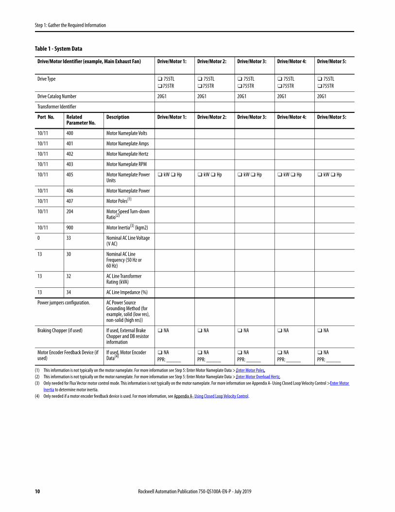
Table 1 provides a place to record the data you need for the rest of the steps in this document.
Record Motor Nameplate and AC Power Data
Record the data to be entered into the parameters during power-up. You can also record data for up to five drive/motor combinations. Use this table to record a descriptive name for each drive/motor combination and their respective parameters.
Rockwell Automation Publication 750-QS100A-EN-P - July 2019 9
Step 1: Gather the Required Information
Table 1 - System Data
Drive/Motor Identifier (example, Main Exhaust Fan) Drive/Motor 1: Drive/Motor 2: Drive/Motor 3: Drive/Motor 4: Drive/Motor 5:
Drive Type ❑ 755TL❑755TR
❑ 755TL❑755TR
❑ 755TL❑755TR
❑ 755TL❑755TR
❑ 755TL❑755TR
Drive Catalog Number 20G1 20G1 20G1 20G1 20G1
Transformer Identifier
Port No. Related Parameter No.
Description Drive/Motor 1: Drive/Motor 2: Drive/Motor 3: Drive/Motor 4: Drive/Motor 5:
10/11 400 Motor Nameplate Volts
10/11 401 Motor Nameplate Amps
10/11 402 Motor Nameplate Hertz
10/11 403 Motor Nameplate RPM
10/11 405 Motor Nameplate Power Units
❑ kW ❑ Hp ❑ kW ❑ Hp ❑ kW ❑ Hp ❑ kW ❑ Hp ❑ kW ❑ Hp
10/11 406 Motor Nameplate Power
10/11 407 Motor Poles(1)
(1) This information is not typically on the motor nameplate. For more information see Step 5: Enter Motor Nameplate Data > Enter Motor Poles.
10/11 204 Motor Speed Turn-down Ratio(2)
(2) This information is not typically on the motor nameplate. For more information see Step 5: Enter Motor Nameplate Data > Enter Motor Overload Hertz.
10/11 900 Motor Inertia(3) (kgm2)
(3) Only needed for Flux Vector motor control mode. This information is not typically on the motor nameplate. For more information see Appendix A- Using Closed Loop Velocity Control >Enter Motor Inertia to determine motor inertia.
0 33 Nominal AC Line Voltage (V AC)
13 30 Nominal AC Line Frequency (50 Hz or 60 Hz)
13 32 AC Line Transformer Rating (kVA)
13 34 AC Line Impedance (%)
Power jumpers configuration. AC Power Source Grounding Method (for example, solid (low res), non-solid (high res))
Braking Chopper (if used) If used, External Brake Chopper and DB resistor information
❑ NA ❑ NA ❑ NA ❑ NA ❑ NA
Motor Encoder Feedback Device (if used)
If used, Motor Encoder Data(4)
(4) Only needed if a motor encoder feedback device is used. For more information, see Appendix A- Using Closed Loop Velocity Control.
❑ NAPPR: _____
❑ NAPPR: _____
❑ NAPPR: _____
❑ NAPPR: _____
❑ NAPPR: _____
10 Rockwell Automation Publication 750-QS100A-EN-P - July 2019

Step 1: Gather the Required Information
Record Velocity Reference and Start/Stop Sources
Use this diagram to help determine where signal and control sources are connected in each of your drives. You need this information when you get to Step 7: Set Up Velocity Reference and Step 8: Set Up Start/Stop.
Figure 1 - Signal Source and Port Locations
IMPORTANT PowerFlex 755T products use the term ‘port’ to designate (in software) the physical location where hardware is located to make it easier to select hardware or functions to program.
Item Description
01, 01A Drive-Mounted HIM (port 1). Install in HIM cradle connection at 01A. A splitter cable (07)could also be connected to the HIM cradle connection.
02, 2A, 2B Port 02 for Handheld or remote HIM connection. A splitter cable (07) can be connected here. If the HIM cradle connector (01A) is not used then the splitter cable provides Port 01 at 02A. Otherwise, 02A and 02B on the splitter cable provide Port 02 and Port 03.
03 Communication option module (port 5 installation shown).
04 Expansion I/O module (port 4 installation shown). Embedded EtherNet/IP
05 Embedded EtherNet/IP.
06 Terminal block TB1 behind the EtherNet/IP port on the main control board.
07 Splitter cable, connects to Port 02 - if the splitter cable is used it provides Port 02 and Port 03.
03
04
ShShPTC–PTC+Ao0–Ao0+Ao1–Ao1+–10V10VC+10VAi0–Ai0+Ai1–Ai1+24VC+24VDiCDi0Di1Di2Di3Di4Di5
02
0505
0606
01
01A
0707
02A 02B
Rockwell Automation Publication 750-QS100A-EN-P - July 2019 11

Step 1: Gather the Required Information
Table 2 - Velocity Reference and Start/Stop Control Sources
Item(1)
03 Are signal sources connected to a communication option module installed in your drive? If yes, note the catalog # and port number for the module. (2)
Drive 1:❑ Yes: Port No. _____❑ NoCatalog #: 20-750-_____
Drive 2:❑ Yes: Port No._____ ❑ NoCatalog #: 20-750-_____
Drive 3:❑ Yes: Port No._____ ❑ NoCatalog #: 20-750-_____
Drive 4:❑ Yes: Port No._____ ❑ NoCatalog #: 20-750-_____
Drive 5:❑ Yes: Port No. _____❑ NoCatalog #: 20-750-_____
Address Information: Address Information: Address Information: Address Information: Address Information:
04 Are signal sources connected to the digital and analog inputs of an I/O option module that is installed in your drive? If yes, note the catalog #, port number and wiring terminal information for the module. (3)
Drive 1:❑ Yes: Port No._____ ❑ NoCatalog #: 20-750-_____
Drive 2:❑ Yes: Port No._____ ❑ NoCatalog #: 20-750-_____
Drive 3:❑ Yes: Port No._____ ❑ NoCatalog #: 20-750-_____
Drive 4:❑ Yes: Port No._____ ❑ NoCatalog #: 20-750-_____
Drive 5:❑ Yes: Port No._____ ❑ NoCatalog #: 20-750-_____
Vel Ref Term: Ai ___
Di 0 Term: _____Di 1 Term: _____Di 2 Term: _____Di 3 Term: _____Di 4 Term: _____DI 5 Term: _____
Ao0 Term: _____Ao1 Term: _____
R0 Term: _____R1 Term: _____T0 Term: _____T1 Term: _____
Vel Ref Term: Ai ___
Di 0 Term: _____Di 1 Term: _____Di 2 Term: _____Di 3 Term: _____Di 4 Term: _____DI 5 Term: _____
Ao0 Term: _____Ao1 Term: _____
R0 Term: _____R1 Term: _____T0 Term: _____T1 Term: _____
Vel Ref Term: Ai ___
Di 0 Term: _____Di 1 Term: _____Di 2 Term: _____Di 3 Term: _____Di 4 Term: _____DI 5 Term: _____
Ao0 Term: _____Ao1 Term: _____
R0 Term: _____R1 Term: _____T0 Term: _____T1 Term: _____
Vel Ref Term: Ai ___
Di 0 Term: _____Di 1 Term: _____Di 2 Term: _____Di 3 Term: _____Di 4 Term: _____DI 5 Term: _____
Ao0 Term: _____Ao1 Term: _____
R0 Term: _____R1 Term: _____T0 Term: _____T1 Term: _____
Vel Ref Term: Ai ___
Di 0 Term: _____Di 1 Term: _____Di 2 Term: _____Di 3 Term: _____Di 4 Term: _____DI 5 Term: _____
Ao0 Term: _____Ao1 Term: _____
R0 Term: _____R1 Term: _____T0 Term: _____T1 Term: _____
05 Is there a connection to the Embedded EtherNet/IP Adapter? If yes, note the IP address and other applicable information. (4)
Drive 1: ❑ Yes ❑ No Drive 2: ❑ Yes ❑ No Drive 3: ❑ Yes ❑ No Drive 4: ❑ Yes ❑ No Drive 5: ❑ Yes ❑ No
Port No. 0IP Address:___:___:___:___
Subnet Mask(if used):___:___:___:___
Gateway Address(if used):___:___:___:___
Port No. 0IP Address:___:___:___:___
Subnet Mask(if used):___:___:___:___
Gateway Address(if used):___:___:___:___
Port No. 0IP Address:___:___:___:___
Subnet Mask(if used):___:___:___:___
Gateway Address(if used):___:___:___:___
Port No. 0IP Address:___:___:___:___
Subnet Mask(if used):___:___:___:___
Gateway Address(if used):___:___:___:___
Port No. 0IP Address:___:___:___:___
Subnet Mask(if used):___:___:___:___
Gateway Address(if used):___:___:___:___
01, 02 Are you using the drive HIM to set the speed reference or for Start/Stop control? If yes, note the HIM port number.
Drive 1:❑ Yes: Port No._____ ❑ No
Drive 2:❑ Yes: Port No._____ ❑ No
Drive 3:❑ Yes: Port No._____ ❑ No
Drive 4:❑ Yes: Port No._____ ❑ No
Drive 5:❑ Yes: Port No._____ ❑ No
(1) Item numbers are referenced to the control pod diagram, Figure 1.(2) See the user manual for the communication option module installed in the drive.(3) See Connections on 11-Series I/O Module - Cat. No. 20-750-11xxx-xxxx or 22-Series I/O Module - Cat. No. 20-750-22xxx-xxxx for information regarding analog I/O parameter assignments. Leave
unused digital and analog assignments blank. See application wiring diagrams to determine the functions of digital and analog I/O that are wired to various I/O option module terminals. Possible motor side control functions that can be assigned to the digital inputs include; Stop, Start, and Run. See the PowerFlex Drives with TotalFORCE Control programming manual, publication 750-PM100, for all motor side control functions available for assignment to digital inputs.
(4) See Configure the Embedded EtherNet/IP Communication Adapter for information regarding methods to set the embedded EtherNet adapter IP address.
12 Rockwell Automation Publication 750-QS100A-EN-P - July 2019
Step 2: Validate the Drive Installation
Step 2: Validate the Drive Installation
It is important that you thoroughly inspect each of your drive installations before applying power for the first time. This is especially important if you did not personally perform the installation tasks. Verify that each drive is ready to be energized when you get to Step 3: Power Up, Configure the Modular Control Profiles.
Verify the Setting of the ENABLE and SAFETY Jumpers• If the ENABLE jumper is removed, you must apply control power to the main control board, port 0 TB1 terminal
<Di0> and <DiC>, to enable the product to operate. No modification of drive parameters are required, port 0 TB1 terminal <Di0> becomes the dedicated product enable input. For more information, see the PowerFlex 750-Series Products with TotalFORCE Control Installation Instructions, publication 750-IN100.
• If the SAFETY jumper is removed, the ENABLE jumper must be installed. If the SAFETY jumper is removed, you must install a safety option module in a valid control pod port. Configuring a safety option module is beyond the scope of this document. See the manual for the safety option that is installed:– Catalog number 20-750-S: PowerFlex 750-Series Safe Torque Off User Manual, publication 750-UM002.– Catalog number 20-750-S1: Safe Speed Monitor Option Module for PowerFlex 750-Series AC Drives Safety
Reference Manual, publication 750-RM001.– Catalog number 20-750-S3: PowerFlex 755 Integrated Safety - Safe Torque Off User Manual,
publication 750-UM004.– Catalog number 20-750-S4: PowerFlex 755/755T Integrated Safety Functions Option Module, publication
750-UM005.
ATTENTION: To avoid an electric shock hazard, the drive must be locked and tagged before continuing Step 2: Validate the Drive Installation. Failure to comply can result in personal injury and/or equipment damage.
Rockwell Automation Publication 750-QS100A-EN-P - July 2019 13
Step 2: Validate the Drive Installation
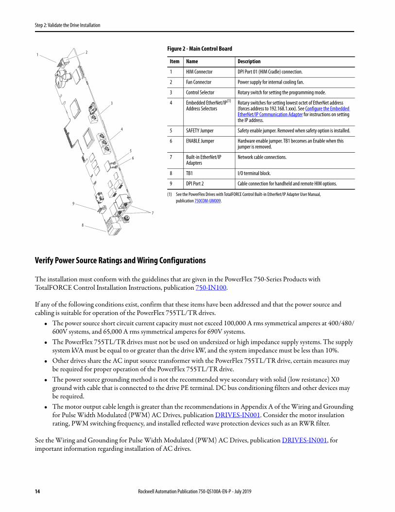
Figure 2 - Main Control Board
Verify Power Source Ratings and Wiring Configurations
The installation must conform with the guidelines that are given in the PowerFlex 750-Series Products with TotalFORCE Control Installation Instructions, publication 750-IN100.
If any of the following conditions exist, confirm that these items have been addressed and that the power source and cabling is suitable for operation of the PowerFlex 755TL/TR drives.
• The power source short circuit current capacity must not exceed 100,000 A rms symmetrical amperes at 400/480/600V systems, and 65,000 A rms symmetrical amperes for 690V systems.
• The PowerFlex 755TL/TR drives must not be used on undersized or high impedance supply systems. The supply system kVA must be equal to or greater than the drive kW, and the system impedance must be less than 10%.
• Other drives share the AC input source transformer with the PowerFlex 755TL/TR drive, certain measures may be required for proper operation of the PowerFlex 755TL/TR drive.
• The power source grounding method is not the recommended wye secondary with solid (low resistance) X0 ground with cable that is connected to the drive PE terminal. DC bus conditioning filters and other devices may be required.
• The motor output cable length is greater than the recommendations in Appendix A of the Wiring and Grounding for Pulse Width Modulated (PWM) AC Drives, publication DRIVES-IN001. Consider the motor insulation rating, PWM switching frequency, and installed reflected wave protection devices such as an RWR filter.
See the Wiring and Grounding for Pulse Width Modulated (PWM) AC Drives, publication DRIVES-IN001, for important information regarding installation of AC drives.
Item Name Description
1 HIM Connector DPI Port 01 (HIM Cradle) connection.
2 Fan Connector Power supply for internal cooling fan.
3 Control Selector Rotary switch for setting the programming mode.
4 Embedded EtherNet/IP(1) Address Selectors
(1) See the PowerFlex Drives with TotalFORCE Control Built-in EtherNet/IP Adapter User Manual, publication 750COM-UM009.
Rotary switches for setting lowest octet of EtherNet address (forces address to 192.168.1.xxx). See Configure the Embedded EtherNet/IP Communication Adapter for instructions on setting the IP address.
5 SAFETY Jumper Safety enable jumper. Removed when safety option is installed.
6 ENABLE Jumper Hardware enable jumper. TB1 becomes an Enable when this jumper is removed.
7 Built-in EtherNet/IP Adapters
Network cable connections.
8 TB1 I/O terminal block.
9 DPI Port 2 Cable connection for handheld and remote HIM options.
1
3
4
8
9
7
6
5
2
14 Rockwell Automation Publication 750-QS100A-EN-P - July 2019
Step 2: Validate the Drive Installation
Verify Power Wiring
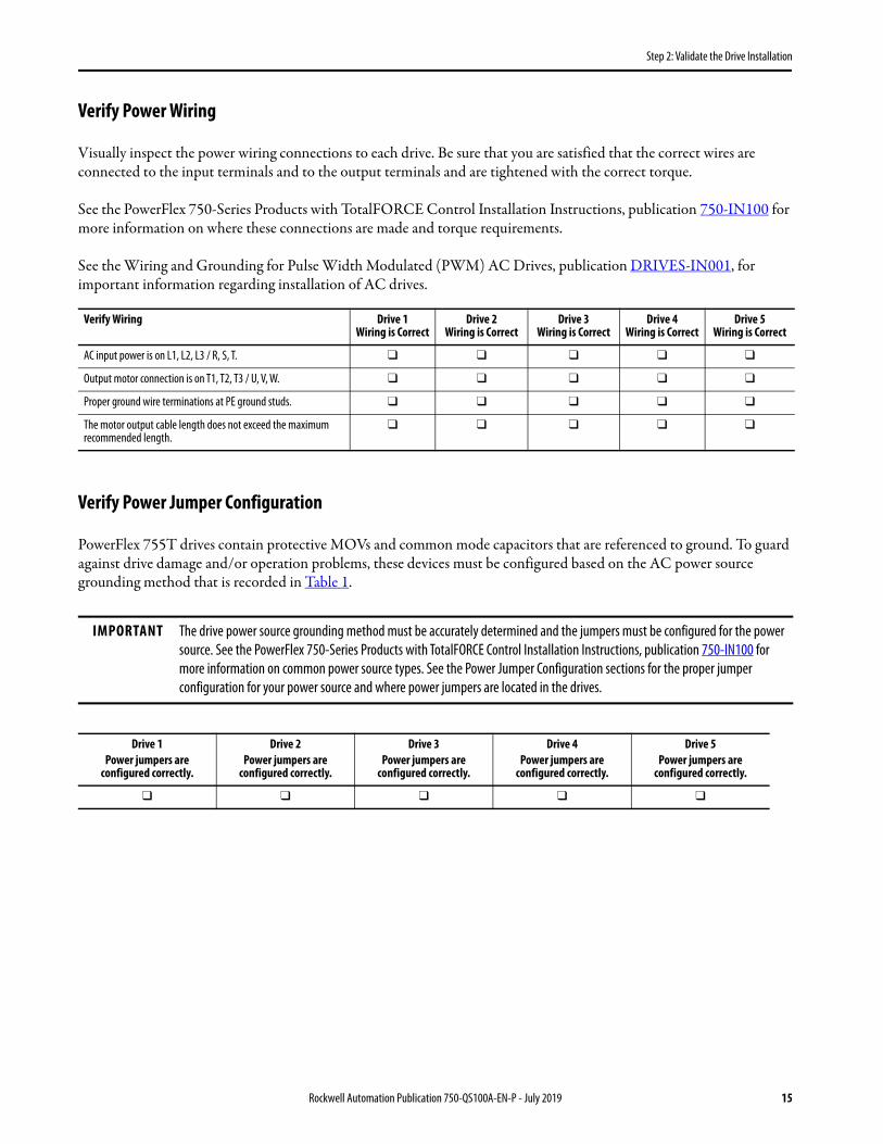
Visually inspect the power wiring connections to each drive. Be sure that you are satisfied that the correct wires are connected to the input terminals and to the output terminals and are tightened with the correct torque.
See the PowerFlex 750-Series Products with TotalFORCE Control Installation Instructions, publication 750-IN100 for more information on where these connections are made and torque requirements.
See the Wiring and Grounding for Pulse Width Modulated (PWM) AC Drives, publication DRIVES-IN001, for important information regarding installation of AC drives.
Verify Power Jumper Configuration
PowerFlex 755T drives contain protective MOVs and common mode capacitors that are referenced to ground. To guard against drive damage and/or operation problems, these devices must be configured based on the AC power source grounding method that is recorded in Table 1.
Verify Wiring Drive 1 Wiring is Correct
Drive 2Wiring is Correct
Drive 3Wiring is Correct
Drive 4Wiring is Correct
Drive 5Wiring is Correct
AC input power is on L1, L2, L3 / R, S, T. ❑ ❑ ❑ ❑ ❑
Output motor connection is on T1, T2, T3 / U, V, W. ❑ ❑ ❑ ❑ ❑
Proper ground wire terminations at PE ground studs. ❑ ❑ ❑ ❑ ❑
The motor output cable length does not exceed the maximum recommended length.
❑ ❑ ❑ ❑ ❑
IMPORTANT The drive power source grounding method must be accurately determined and the jumpers must be configured for the power source. See the PowerFlex 750-Series Products with TotalFORCE Control Installation Instructions, publication 750-IN100 for more information on common power source types. See the Power Jumper Configuration sections for the proper jumper configuration for your power source and where power jumpers are located in the drives.
Drive 1Power jumpers are
configured correctly.
Drive 2Power jumpers are
configured correctly.
Drive 3Power jumpers are
configured correctly.
Drive 4Power jumpers are
configured correctly.
Drive 5Power jumpers are
configured correctly.
❑ ❑ ❑ ❑ ❑
Rockwell Automation Publication 750-QS100A-EN-P - July 2019 15

Step 2: Validate the Drive Installation
Verify I/O Wiring
To configure a drive correctly, you must know the source of the velocity reference and the start/stop commands. There are four places where signal sources (such as push buttons, potentiometers, or communication network cabling, or HIM) are connected to the drive.
1. The main control board.• Embedded EtherNet/IP™ port• Terminal block TB1 (Di0)
2. An I/O option module.
3. A communication option module.
4. A HIM.
5. Analog input or preset speed.
16 Rockwell Automation Publication 750-QS100A-EN-P - July 2019

Step 3: Power Up, Configure the Modular Control Profiles
Step 3: Power Up, Configure the Modular Control Profiles
In this step, you power up the drive and configure the drive modular control profiles and system properties. Modular Control Profiles are parts of the drive that change to match your application needs. A power cycle or drive reset is required for the new configuration to be applied. Modular Control Profiles improve the user interface and performance.
Preparation
Use the following table to record your configurations and preferences. See the detailed description below the table for more information about what to record in this table.
Table 3 - Configurations and Preferences
Drive/Motor Name (example, Main Exhaust Fan)
Port No.
Related Parameter No.
Description Drive/Motor 1: Drive/Motor 2: Drive/Motor 3: Drive/Motor 4: Drive/Motor 5:
0 33 Voltage Class (1)
(Low, High)
0 35 Duty Rating Class (2)
(LD, ND, HD)
0 46 Velocity Units(Hertz, RPM)
0 65 Induction Motor Control Mode (3)
(VHz, SV, Econ, FV)
0 70 Application Select (4)
(None, PID, Torque Prove)
10 110 Stop Mode (5)
(Coast, Ramp, Current Limit, Decel Hold)
10 116 Motor Side DC Bus Regulation Mode (6)
(Disabled, Adjust Frequency)
(1) Low for 400V and 600V drives. High for 480V and 690V drives. See Enter the Voltage Class for more information about this setting.(2) Depends on the application overload requirements. LD = 110% for 60 sec, ND = 110%/150% for 60 s/3 s, HD = 150%/180% for 60 s/3 s. See Enter the Duty Rating for more information about this
setting.(3) For most applications, select SV (Sensorless Vector) or Econ (Econ SV). If your application requires closed loop velocity control with encoder feedback, select FV (Flux Vector).
See Enter the Motor Control Mode for more information about this setting.(4) For most applications, select ‘None‘. See Enter the Application Selection for more information about this setting.(5) For most applications, select ‘Ramp’. See Enter the Motor Stop Mode for more information about this setting. Note that parameters associated with Port 10 change after a power cycle if Port 0,
Parameter 65 is changed.(6) For PowerFlex 755TL drives, select ‘Adjust Frequency’. For PowerFlex 755TR drives, select ‘Disabled’. See Enter the Motor Side Bus Regulation Mode for more information about this setting. Note that
parameters associated with Port 10 change after a power cycle if Port 0, Parameter 65 is changed.
Rockwell Automation Publication 750-QS100A-EN-P - July 2019 17
Step 3: Power Up, Configure the Modular Control Profiles
Startup Using the HIM
The PowerFlex 20-HIM-A6 / -C6S HIM User Manual, publication 20HIM-UM001, provides detailed instructions on how to use the Human Interface Module capabilities for configuring PowerFlex 750-Series drive settings.
The PowerFlex 755T product does not support Assisted Startup using the HIM. You must manually select parameters as directed in the following procedure.
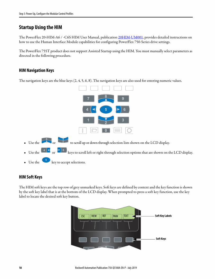
HIM Navigation Keys
The navigation keys are the blue keys (2, 4, 5, 6, 8). The navigation keys are also used for entering numeric values.
• Use the or to scroll up or down through selection lists shown on the LCD display.
• Use the or keys to scroll left or right through selection options that are shown on the LCD display.
• Use the key to accept selections.
HIM Soft Keys
The HIM soft keys are the top row of grey unmarked keys. Soft keys are defined by context and the key function is shown by the soft key label that is at the bottom of the LCD display. When prompted to press a soft key function, use the key label to locate the desired soft key button.
ESC VIEW REF PAR# TEXT Soft Key Labels
Soft Keys
18 Rockwell Automation Publication 750-QS100A-EN-P - July 2019
Step 3: Power Up, Configure the Modular Control Profiles
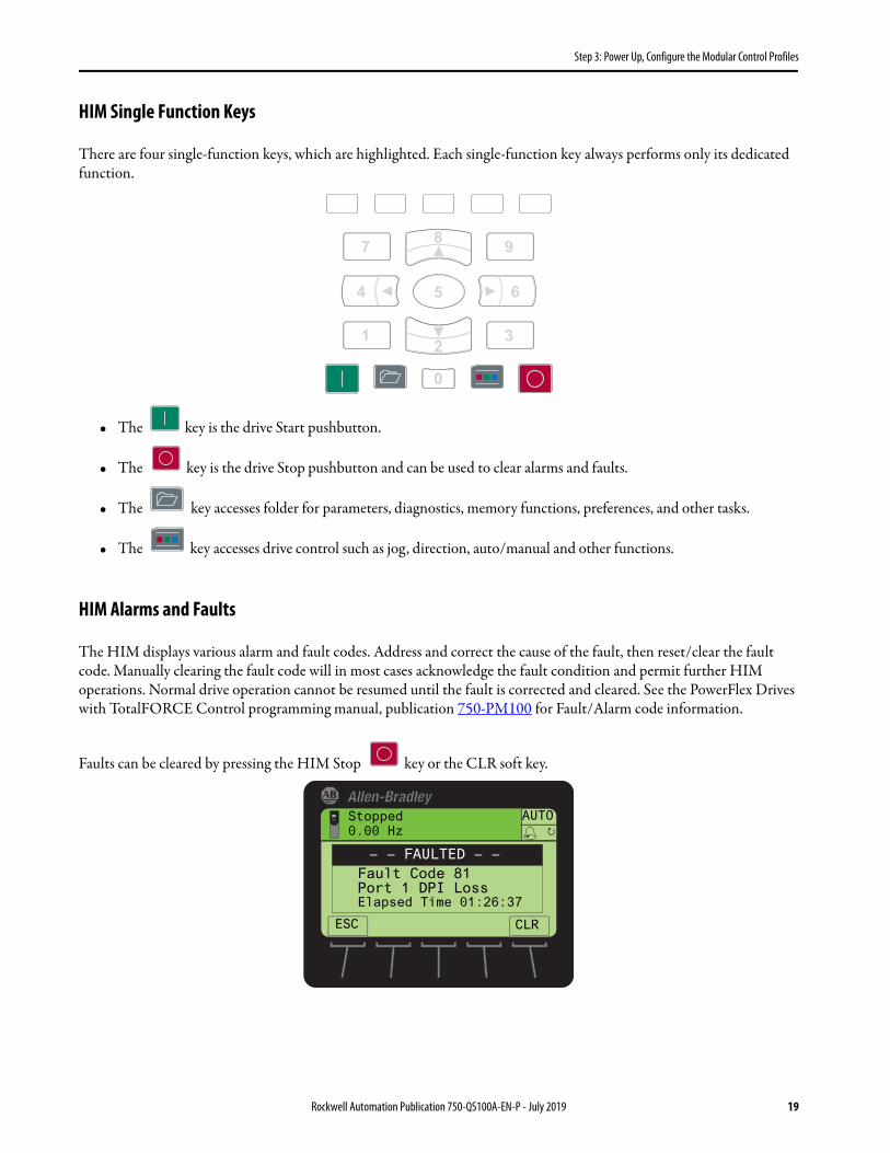
HIM Single Function Keys
There are four single-function keys, which are highlighted. Each single-function key always performs only its dedicated function.
• The key is the drive Start pushbutton.
• The key is the drive Stop pushbutton and can be used to clear alarms and faults.
• The key accesses folder for parameters, diagnostics, memory functions, preferences, and other tasks.
• The key accesses drive control such as jog, direction, auto/manual and other functions.
HIM Alarms and Faults
The HIM displays various alarm and fault codes. Address and correct the cause of the fault, then reset/clear the fault code. Manually clearing the fault code will in most cases acknowledge the fault condition and permit further HIM operations. Normal drive operation cannot be resumed until the fault is corrected and cleared. See the PowerFlex Drives with TotalFORCE Control programming manual, publication 750-PM100 for Fault/Alarm code information.
Faults can be cleared by pressing the HIM Stop key or the CLR soft key.
Stopped0.00 Hz
AUTO
Fault Code 81Port 1 DPI LossElapsed Time 01:26:37
– – FAULTED – –
ESC CLR
Rockwell Automation Publication 750-QS100A-EN-P - July 2019 19
Step 3: Power Up, Configure the Modular Control Profiles
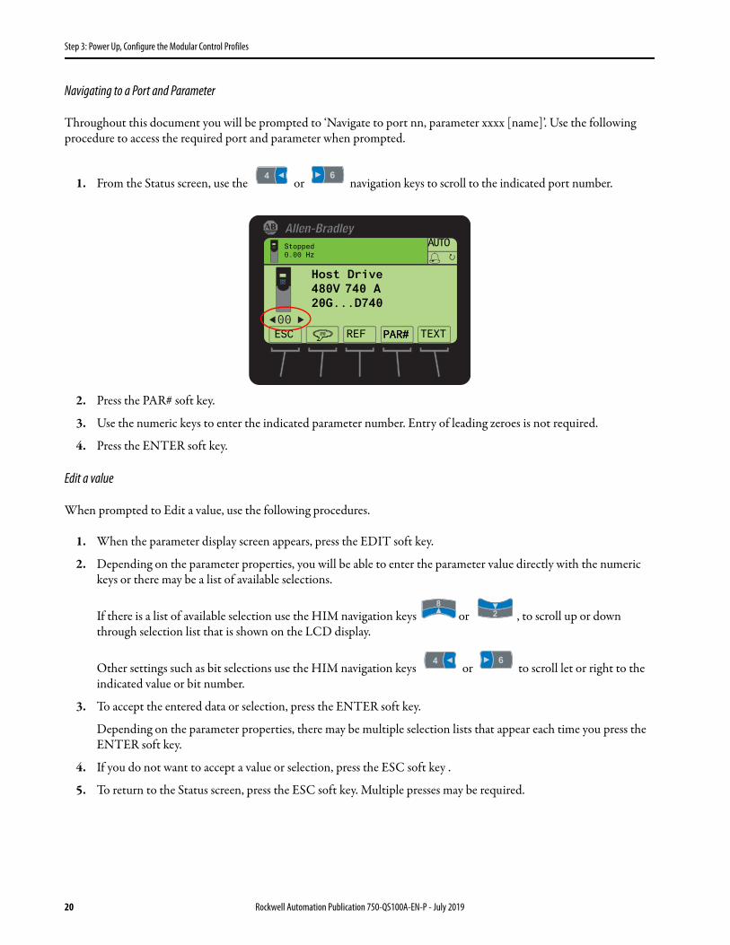
Navigating to a Port and Parameter
Throughout this document you will be prompted to ‘Navigate to port nn, parameter xxxx [name]’. Use the following procedure to access the required port and parameter when prompted.
1. From the Status screen, use the or navigation keys to scroll to the indicated port number.
2. Press the PAR# soft key.
3. Use the numeric keys to enter the indicated parameter number. Entry of leading zeroes is not required.
4. Press the ENTER soft key.
Edit a value
When prompted to Edit a value, use the following procedures.
1. When the parameter display screen appears, press the EDIT soft key.
2. Depending on the parameter properties, you will be able to enter the parameter value directly with the numeric keys or there may be a list of available selections.
If there is a list of available selection use the HIM navigation keys or , to scroll up or down through selection list that is shown on the LCD display.
Other settings such as bit selections use the HIM navigation keys or to scroll let or right to the indicated value or bit number.
3. To accept the entered data or selection, press the ENTER soft key.
Depending on the parameter properties, there may be multiple selection lists that appear each time you press the ENTER soft key.
4. If you do not want to accept a value or selection, press the ESC soft key .
5. To return to the Status screen, press the ESC soft key. Multiple presses may be required.
00
Stopped0.00 Hz
AUTO
Host Drive480V 740 A20G...D740
ESC REF TEXTPAR#PAR#
20 Rockwell Automation Publication 750-QS100A-EN-P - July 2019

Step 3: Power Up, Configure the Modular Control Profiles
Power the Drive
The following procedures describe energizing and setting parameters for your PowerFlex 755T standalone drive installation.
To energize and de-energize the drive AC power:
For Drives without 24V Auxiliary Power
1. Energize the 3-phase power source to the drive.
2. For Frames 7…15, turn the Fused Disconnect handle on the drive input bay to the ON position.
3. After the drive boots up, clear faults.
4. For Frames 7…15, to de-energize the drive, turn the Fused Disconnect handle on the drive input bay to the OFF position.
5. De-energize the 3-phase power source to the drive.
For Drives with 24V Auxiliary Power
1. Energize the three-phase power source to the drive.
2. For Frames 7…15, turn the Fused Disconnect handle on the drive input bay to the ON position.
3. After the drive boots up, clear any faults.
4. Energize the 24V Auxiliary Power supply source.
5. Keep the 24V Auxiliary Power source energized even if the AC power is de-energized. This maintains operation of the control pod port devices and communication adapters.
6. For Frames 7…15, to de-energize the drive, turn the Fused Disconnect handle on the drive input bay to the OFF position.
7. De-energize the 3-phase power source to the drive.
If you need to reset the parameters to factory defaults, refer to Setting Factory Defaults in Appendix A.
If you are prompted to select the language:
1. Use the HIM navigation keys to scroll through the list of selections to highlight the desired display language.
2. To accept the setting, press the ENTER soft key.
ATTENTION: Power must be applied to the drive to perform the following start-up procedure. Some of the voltages present are at incoming line potential. To avoid electric shock hazard or damage to equipment, allow only qualified service personnel to perform the following procedure. Thoroughly read and understand the procedure before beginning.
IMPORTANT If the drive was previously powered and configured, and is being repurposed for this application, reset the drive parameters following the instructions in Appendix A, Setting Factory Defaults.
Rockwell Automation Publication 750-QS100A-EN-P - July 2019 21

Step 3: Power Up, Configure the Modular Control Profiles
Configure the Motor Side Inverter.
Enter the following data gathered in Table 3.
Enter the Voltage Class
A change to this parameter is needed only when you are applying a drive on a voltage other than what the catalog number specifies.
• For 400/480V products, ‘Low Voltage’ selects 400V and ‘High Voltage’ selects 480V.• For 600/690V products, ‘Low Voltage’ selects 600V and ‘High Voltage’ selects 690V.
1. Navigate to port 0, parameter 33 [VoltageClass Cfg] and press the EDIT soft key.
2. Edit the value to 0 ‘Low Voltage’ or 1 ‘High Voltage’, corresponding to the data collected in Table 3 and press the ENTER soft key.
Enter the Duty Rating
The duty class parameter allows you to select the continuous and overload modes of operation. The value of this parameter affects the continuous current rating of the drive.
• Normal Duty (ND) - Selects the normal continuous rating, with overload ratings of 110% for 60 seconds and 150% for 3 seconds.
• Heavy Duty (HD) - Provides a lower continuous rating, with overload ratings of 150% for 60 seconds and 180% for 3 seconds.
• Light Duty (LD) - provides the highest continuous rating, with an overload rating of 110% for 60 seconds. Not available on all drive ratings.
1. Navigate to port 0, parameter 35 [Duty Rating Cfg].
2. Press the EDIT soft key.
3. Edit the value to 0 ‘Normal Duty’, 1 ‘Heavy Duty’, or 2 ‘Light Duty’, corresponding to the data collected in Table 3.
4. Press the ENTER soft key.
Stopped0.000 Hz
AUTO
Select Language to UseEnglish FrancaiseEspanolItaliano
ENTER
22 Rockwell Automation Publication 750-QS100A-EN-P - July 2019

Step 3: Power Up, Configure the Modular Control Profiles
Enter the Velocity Units
This parameter allows you to select either Hertz (Hz) or Revolutions per Minute (RPM) as the units for velocity (speed).
1. Navigate to port 0, parameter 46 [Velocity Units].
2. Press the EDIT soft key.
3. Edit the value to 0 ‘Hz’ or 1 ‘RPM’, corresponding to the data collected in Table 3.
4. Press the ENTER soft key.
Enter the Motor Control Mode
Determine how the drive controls the motor. You can choose from the following modes for Induction Motors:• Volts per Hertz (VHz) - The most basic form of motor control useful for variable torque applications. These
include pumps, fans, and multiple motors in parallel.• Sensorless Vector (SV) - An enhanced form of V/Hz control useful variable torque and simple constant torque
applications. Sensorless vector produces better torque at low frequencies than volts per hertz. Motor ID test recommended.
• Economize (Econ) - An enhanced form of Sensorless Vector control designed to reduce energy consumption when the drive is not accelerating. Motor ID test recommended.
• Flux Vector (FV) - A control mode that is designed for precise Torque, Velocity and/or Position regulation. Usually implements a motor feedback device. Useful for variable torque, constant torque, and constant power applications. Provides precise position and velocity tracking. Provides excellent disturbance rejection. This mode is needed for position and load sharing applications. Motor ID test and Inertia test are required.
1. Navigate to port 0, parameter 65 [Pri MtrCtrl Mode].
2. Press the EDIT soft key.
3. Edit the value to 1 ‘InductionVHz’, 2 ‘Induction SV’, 3 ‘Induct Econ’ or 4 ‘Induction FV’, corresponding to the data collected in Table 3.
4. Press the ENTER soft key.
Enter the Application Selection
You can add Process PID or Torque Prove application functionality to determine which application parameters are present in virtual port 9. This is only needed when you are using Process PID or Torque Prove. The following options are available:
• None - leaves port 9 empty. This is the default setting• Process PID only - provides a PID regulator for process applications in port 9. Use Process PID for pressure or
flow transducers on fan or pump applications; you can also use it for tension transducers on winding applications.• Torque Prove - provides a mechanism for coordinating the motor and mechanical brake on lifting applications.
This selection loads these parameters and the Process PID parameters into port 9.
1. Navigate to port 0, parameter 70 [Application Sel].
2. Press the EDIT soft key.
3. Edit the value to 0 ‘None’, 1 ‘ProcPID Only’ or 2 ‘Torque Prove’, corresponding to the data collected in Table 3.
4. Press the ENTER soft key. The drive power must be cycled for settings 1 or 2 to take effect.
Rockwell Automation Publication 750-QS100A-EN-P - July 2019 23

Step 3: Power Up, Configure the Modular Control Profiles
Enter the Motor Stop Mode
Select how the drive executes a stop command. For operation with a controller, Stop Mode A defines the method that is used for a Normal Stop. The default motor stop mode is ‘Ramp’.
• Coast - the motor side inverter immediately stops modulating (stops gating its power devices), and stops the motor side inverter from powering the motor. In most applications, Coast causes the motor to coast to a standstill.
• Ramp - the motor side inverter decelerates the motor, at a rate that is defined by the active Decel Time (10/11:1917 [VRef Decel Time1] or 10:1918 [VRef Decel Time2]), until it reaches the Zero Speed threshold, 10/11:146 [Zero Speed Limit]. Modulation is stopped (stops gating its power devices), when it reaches the Zero Speed threshold.
• Current Limit - the motor side inverter decelerates the motor at a rate where the Decel Time is 0.1 seconds. Deceleration does not exceed the Current Limit to stop at this rate.
• Decel To Hold - the motor side inverter decelerates the motor, at a rate that is defined by the active Decel Time, until it reaches the Zero Speed threshold. It holds by continuing to modulate with a zero speed (zero frequency) output. Hold continues until there is a new start command, new run command, or another kind of stop command.
1. Navigate to port 10, parameter 110 [Mtr Stop Mode A].
2. Press the EDIT soft key.
3. Edit the value to 0 ‘Coast’, 1 ‘Ramp’, 2 ‘Current Lmt’ or 3 ‘DecelToHold’, corresponding to the data collected in Table 3.
4. Press the ENTER soft key.
Enter the Motor Side Bus Regulation Mode
Selects how the motor side inverter attempts to mitigate rising DC bus voltage during motor regeneration.• Disabled - the motor side inverter does nothing to regulate the DC bus voltage. This is the typical setting for a
755TR. In this mode, the regenerative line side converter or an external DC bus voltage control (brake resistor, regen module) is required to regulate the DC bus voltage during motor regeneration.
• Adjust Output Frequency - the motor side inverter adjusts its fundamental output frequency or torque, depending on the motor control mode, to reduce the amount of motor regeneration. This is the typical setting for a 755TL. The use of this option may result in extended deceleration times.
The default bus regulation mode is 'Adjust Freq'.• If you are using a PowerFlex 755TR regenerative drive, you set this parameter to 'Disabled'.• If you are using a PowerFlex 755TL low harmonic drive, you set this parameter to 'Adjust Freq'. If you have
installed an external brake chopper and dynamic brake resistor, set the parameter to 'Disabled'.
1. Navigate to port 10, parameter 116 [Bus Reg Mode A] and press the EDIT soft key.
2. Edit the value to 0 'Disabled' or 1 'Adjust Freq', corresponding to the data collected in Table 3 and press the ENTER soft key.
24 Rockwell Automation Publication 750-QS100A-EN-P - July 2019

Step 3: Power Up, Configure the Modular Control Profiles
Reset Device and Verify the Configurations
It is necessary to perform a Reset Device in order for the changes that were entered earlier to be accepted. You can cycle power to the drive and control pod or use the HIM. See Appendix A- Reset Device, for more information about resetting devices.
To verify the configurations, navigate to port 0 and select the following parameters to verify the actual values of configuration parameters:
Configure the Embedded EtherNet/IP Communication Adapter
If you are using a communication adapter, configure the address corresponding to the data collected in Table 2.
If you are using a communication option module (20-750 series), refer to the appropriate 750COM-UM user manual for more information about setting communication addresses.
See PowerFlex Drives with TotalFORCE Control Built-in EtherNet/IP Adapter user manual, publication 750COM-UM009, for more information about configuring the embedded EtherNet adapter.
There are three methods for configuring the embedded EtherNet/IP IP address in the adapter:
1. Adapter Rotary Switches - Use the switches when working on a simple, isolated network (for example, 192.168.1.xxx) that has other products with switches to set their IP addresses, does not need to be accessed from outside the network, and you prefer a simplified node addressing method. The three adapter switches are read when the drive powers up, and represent three decimal digits from top to bottom (see Figure 3).a. Set the rotary switches to a valid address (001-254) corresponding to the data collected in Table 2. The adapter
will use that value as the lower octet of its IP address (192.168.1.xxx, where xxx = rotary switch settings), along with a subnet mask of 255.255.255.0 and there will be no gateway configured. Also, the setting for adapter parameter 0:300 [Net Addr Sel] is automatically ignored.
b. To accept the changes to IP address switches, perform a Reset Device. See Appendix A- Reset Device for more information.
2. BOOTP or DHCP Server - If you prefer to control the IP addresses of devices using a server, use BOOTP/DHCP. The IP address, subnet mask, and gateway addresses are then provided by the BOOTP/DHCP server.
3. Adapter Parameters - Use adapter parameters when you want more flexibility in configuring the IP address, or you need to communicate outside the control network using a gateway. The IP address, subnet mask, and gateway addresses will then come from the adapter parameters you set.a. When using this method, set the adapter rotary switches to 999. See Figure 3 and its accompanying table for all
possible switch settings and their related descriptions.b. Navigate to port 0, parameter 300 [Net Addr Sel]. Press the EDIT soft key. Edit to a value of 1 'Parameters'.
Press the ENTER soft key.
IMPORTANT You must perform a Reset Device to load the modified values of these parameters.
0:34 [VoltageClass Act] 0:47 [Vel Units Act] 0:71 [Application Act]
0:36 [Duty Rating Act] 0:66 [Pri MtrCtrl Act]
Rockwell Automation Publication 750-QS100A-EN-P - July 2019 25

Step 3: Power Up, Configure the Modular Control Profiles
c. To accept the switch and parameter setting changes, perform a Reset Device. See Appendix A- Reset Device for more information.
d. Verify the changes by navigating to port 0, parameter 301 [Net Addr Src]. The value should be 1 'Parameters'.
e. Navigate to port 0, parameters 302…305 [IP Addr Cfg 1…4] corresponding to the data collected in Table 2. Press the EDIT soft key. Edit the value of each IP address octet. Press the ENTER soft key. For example, set the IP address to 10.20.3.123;– 0:302 [IP Addr Cfg 1] = 10– 0:303 [IP Addr Cfg 2] = 20– 0:304 [IP Addr Cfg 3] = 3– 0:305 [IP Addr Cfg 4] = 123
f. Navigate to port 0, parameters 306…309 [Subnet Cfg 1…4] corresponding the data collected in Table 2. Press the EDIT soft key. Edit the value of each subnet mask octet. Press the ENTER soft key. The subnet mask cannot be set to 0.0.0.0
g. Navigate to port 0, parameters 310…313 [Gateway Cfg 1…4] corresponding to the data collected in Table 2. Press the EDIT soft key. Edit the value of each gateway address octet. Press the ENTER soft key.If the gateway address is set to 0.0.0.0, the drive can only communicate with devices on the same subnet as the drive. It is not able to communicate with devices on other subnets. If the gateway address is not set to 0.0.0.0, then it must be set to an address that is on the same subnet as the IP address of the drive.
h. To accept the switch and parameter setting changes, perform a Reset Device. See Appendix A- Reset Device section for more information.
i. Verify the entered values of parameters 0:302…313.
IMPORTANT Regardless of the method used to set the IP address on the adapter, each node on the EtherNet/IP network must have a unique IP address. To accept IP address changes, you must perform a Reset Device.
26 Rockwell Automation Publication 750-QS100A-EN-P - July 2019
Step 3: Power Up, Configure the Modular Control Profiles
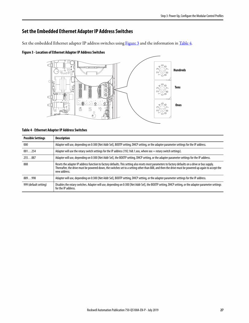
Set the Embedded Ethernet Adapter IP Address Switches
Set the embedded Ethernet adapter IP address switches using Figure 3 and the information in Table 4.
Figure 3 - Location of Ethernet Adapter IP Address Switches
Table 4 - Ethernet Adapter IP Address Switches
Possible Settings Description
000 Adapter will use, depending on 0:300 [Net Addr Sel], BOOTP setting, DHCP setting, or the adapter parameter settings for the IP address.
001…254 Adapter will use the rotary switch settings for the IP address (192.168.1.xxx, where xxx = rotary switch settings).
255…887 Adapter will use, depending on 0:300 [Net Addr Sel], the BOOTP setting, DHCP setting, or the adapter parameter settings for the IP address.
888 Resets the adapter IP address function to factory defaults. This setting also resets most parameters to factory defaults on a drive or bus supply. Thereafter, the drive must be powered down, the switches set to a setting other than 888, and then the drive must be powered up again to accept the new address.
889…998 Adapter will use, depending on 0:300 [Net Addr Sel], BOOTP setting, DHCP setting, or the adapter parameter settings for the IP address.
999 (default setting) Disables the rotary switches. Adapter will use, depending on 0:300 [Net Addr Sel], the BOOTP setting, DHCP setting, or the adapter parameter settings for the IP address.
Hundreds
Tens
Ones
Rockwell Automation Publication 750-QS100A-EN-P - July 2019 27
Step 4: Configure the Line Side Converter
Step 4: Configure the Line Side Converter
In this step you configure the line side converter.
The line side converter regulation parameters can usually be left at the default values. If you are having issues or alarm/faults, refer to Appendix A- Line Side Converter Settings.
Enter Line Side Converter Settings
1. Navigate to port 13, parameter 30 [Nom Line Freq]. Press the EDIT soft key.
2. If necessary, edit the nominal line frequency in Hertz, corresponding to the data collected in Table 1.
3. Press the ENTER soft key.
4. Navigate to port 13, parameter 32 [AC Line kVA A]. Press the EDIT soft key.
5. Edit the supply transformer power rating in kVA, corresponding to the data collected in Table 1.
6. Press the ENTER soft key.
7. Navigate to port 13, parameter 34 [AC Line Imped% A]. Press the EDIT soft key.
8. Edit the power source line impedance in percent, corresponding to the data collected in Table 1.
9. Press the ENTER soft key.
28 Rockwell Automation Publication 750-QS100A-EN-P - July 2019

Step 5: Enter Motor Nameplate Data
Step 5: Enter Motor Nameplate Data
In this step, you configure the Motor Side Inverter Control to contain the motor nameplate information.
Enter Motor Nameplate Data
1. Navigate to port 10, parameter 400 [Motor NP Volts]. Press the EDIT soft key.
2. Edit the motor nameplate voltage to match the data recorded in Table 1.
3. Press the ENTER soft key.
4. Navigate to port 10, parameter 401 [Motor NP Amps]. Press the EDIT soft key.
5. Edit the motor nameplate full load current in amps, to match the data collected Table 1. Press the ENTER soft key.
6. Navigate to port 10, parameter 402 [Motor NP Hertz]. Press the EDIT soft key.
7. Edit the motor nameplate fundamental frequency in Hertz, to match the data collected Table 1.
8. Press the ENTER soft key.
9. Navigate to port 10, parameter 403 [Motor NP RPM]. Press the EDIT soft key.
10. Edit the motor nameplate base speed in RPM, to match the data collected Table 1.
11. Press the ENTER soft key.
12. Navigate to port 10, parameter 405 [Mtr NP Pwr Units]. Press the EDIT soft key.
13. Edit the value to 0 ‘HP’ or 1 ‘kW’, to match the motor nameplate power units collected Table 1.
14. Press the ENTER soft key.
15. Navigate to port 10, parameter 406 [Motor NP Power]. Press the EDIT soft key.
16. Edit the motor nameplate power, to match the data collected Table 1.
17. Press the ENTER soft key.
Enter Motor Poles
If the number of motor poles is not on the motor nameplate, contact the motor manufacturer and confirm the number of motor poles.
The number of motor poles is ALWAYS an even integer multiple of 2.
Rockwell Automation Publication 750-QS100A-EN-P - July 2019 29

Step 5: Enter Motor Nameplate Data
Use this table to help determine the number of poles. The motor NP RPM will always be less than the Sync RPM by the amount of motor slip RPM. If the motor NP Hertz is not 50 Hz or 60 Hz, or if the motor has a low NP RPM, contact the motor manufacturer and confirm the number of poles.
1. Navigate to port 10, parameter 407 [Motor Poles]. Press the EDIT soft key.
2. Edit the number of motor poles to match the data collected Table 1.
3. Press the ENTER soft key.
Enter Motor Overload Hertz
The motor OL hertz is typically not on the motor nameplate. This information is available from the motor manufacturer data sheets. Motor OL hertz is the fundamental frequency below which the motor cannot deliver rated torque continuously without the possibility of overheating. This is sometimes referred to as the 'speed turn-down ratio'. Self-cooled motors with Totally Enclosed Non-Ventilated (TENV), Drip Proof Guarded (DPG), and Totally Enclosed Fan Cooled (TEFC) enclosures, have shaft driven cooling fans that cannot produce the volume and pressure of cooling air that is required to continuously produce rated motor torque, without motor overheating when operated below the minimum speed turn-down frequency. Motors with separately powered cooling fans, such as Totally Enclosed Blower Cooled (TEBC), Drip Proof Guarded Force Ventilated (DPG-FV) enclosures can typically be operated to zero speed without overload hertz derating.
For example, a 60 Hz base speed TEFC motor with 4:1 speed turndown ratio can only produce rated torque continuously down to 60 Hz / 4 = 15 Hz. In this example, parameter 10:204 [Mtr OL Hertz] would be set to 15 Hz.
Another example is a 60 Hz base speed TEBC blower cooled motor with a 1000:1 speed turndown ratio. In this case, parameter 10:204 [Mtr OL Hertz] would be set to 60 Hz / 1000 = 0.06 Hz or 0 Hz.
Setting parameter 10:204 [Mtr OL Hertz] does not affect the drives capability to deliver motor current or limit output current in any way. Parameter 10:204 only sets the threshold where the motor overload counter begins to increment.
1. Navigate to port 10, parameter 204 [Mtr OL Hertz]. Press the EDIT soft key.
2. Edit the overload threshold frequency in Hertz, based on the data collected in Table 1 and the previous calculations.
3. Press the ENTER soft key.
No. Poles Sync RPMNP Hertz = 60 Hz
Sync RPMNP Hertz = 50 Hz
2 3600 3000
4 1800 1500
6 1200 1000
8 900 750
10 720 600
12 600 500
30 Rockwell Automation Publication 750-QS100A-EN-P - July 2019

Step 6: Autotune the Motor Side Inverter Control
Step 6: Autotune the Motor Side Inverter Control
In this step, you perform direction and identification tests using the HIM Autotune routines.
These tests require use of the HIM Start key . Verify that parameter 0:41 [Logic Mask] bits 01…03 are enabled (set to '1') to allow operation with the HIM module port you are using. See Appendix A- Disable the HIM Start Function for more information.
Perform the Direction Test
1. Navigate to port 10, parameter 910 [Autotune]. Press the EDIT soft key.
2. Edit the value to 1 ‘Direction’.
3. Press the ENTER soft key.
4. Press the Start key to start motor rotation.
You can press the Stop key anytime during this test to stop motor rotation.
5. Address the motor rotation direction.
If the motor direction is opposite to application requirements, you have two alternatives:• Stop the drive, shutdown, and safely lockout drive power sources. Exchange any two motor output leads on the
drive output.• Navigate to port 10, parameter 420 [Mtr Cfg Options]. Press the EDIT soft key. Use the HIM navigation keys
to select bit 4. Enter a value of 1. Press the ENTER soft key. This electronically reverses the phase rotation of the applied voltage, effectively reversing the direction of rotation.
Perform the Motor ID Test
These tests are only used in Sensorless Vector, Economize, and Flux Vector motor control modes. The preferred method for the Motor ID Test is 'Rotate MtrID', however, this requires that the motor is uncoupled from the load and can safely be rotated up to base speed. If the motor is coupled to the load or cannot be rotated, then perform the 'Static MtrID' test instead.
IMPORTANT During this test, the drive uses an internal reference that is positive (forward). During operation and other tests, the drive uses an external reference that you select. An external reference can include the HIM, analog input, or communicated reference. The direction of rotation depends on the polarity (direction) of that external reference. Make sure the external reference moves the motor in the intended direction.
IMPORTANT If you reset parameters to defaults, this parameter will be reset to 0 and the motor may rotate in the incorrect direction.
Rockwell Automation Publication 750-QS100A-EN-P - July 2019 31

Step 6: Autotune the Motor Side Inverter Control
See the Auto Tuning section in the PowerFlex 755T Flux Vector Tuning application technique, publication 750-AT006, for more information about the Auto Tuning features of the drive.
It is only necessary to conduct one of these tests.
Static Motor ID Test
1. Navigate to port 10, parameter 910 [Autotune]. Press the EDIT soft key.
2. Edit to a value of 2 ‘Static MtrID’.
3. Press the ENTER soft key.
Static Tune measures the following induction motor parameters;• Stator Resistance, parameter 10:512 [u IM Stator Res]• Stator Leakage Inductance, parameter 10:515 [u IM Leakage L]. Only in Flux Vector motor control mode.• Stator Resistance Compensation, parameter 10:524 [u IM StatResComp]. Only in Flux Vector motor control
mode when motor feedback is not used.
4. To begin the test, press the Start key. The top line of the HIM will say Autotuning.
You can press the Stop key anytime during this test to stop the motor rotation. The HIM will show a 10032 AutoTune Aborted fault.
5. Wait for the test to complete. The drive will stop and the HIM status display will indicate 'Stopped'.
6. Navigate to port 10, parameter 510 [MtrParam C/U Sel]. Press the EDIT soft key.
7. Edit to a value of 1 ‘User Entered’.
8. To select the measured results from the Static Motor ID test, instead of the values estimated from the motor nameplate data, press the ENTER soft key.
Rotate Motor ID Test
1. Navigate to port 10, parameter 910 [Autotune]. Press the EDIT soft key. Enter a value of 3 ‘Rotate MtrID’. Press the ENTER soft key.
Rotate Tune measures the following induction motor parameters;• Stator Resistance, parameter 10:512 [u IM Stator Res].• Flux Current, parameter 10:518 [u Flux Cur Ref ].• Stator Leakage Inductance, parameter 10:515 [u IM Leakage L]. Only in Flux Vector motor control mode.• Slip RPM, parameter 10:490 [u Slip RPM atFLA]. Only in Flux Vector motor control mode when motor
feedback is used.• Stator Resistance Compensation, parameter 10:524 [u IM StatResComp]. Only in Flux Vector motor control
mode when motor feedback is not used.• EncoderLess Angle Compensation, parameter 10:521 [u EncLs AngCmp]. Only in Flux Vector motor control
mode when motor feedback is not used.
IMPORTANT The motor should be uncoupled from the load. The motor will rotate during this test. Verify that the area around the motor is safely secured and the motor shaft can freely rotate up to the motor nameplate base speed.
32 Rockwell Automation Publication 750-QS100A-EN-P - July 2019

Step 6: Autotune the Motor Side Inverter Control
2. To begin the test, press the Start key.
You can press the Stop key anytime during this test to stop the motor rotation.
3. Wait for the test to complete. The drive will stop and the HIM status display will indicate 'Stopped'.
4. Navigate to port 10, parameter 510 [MtrParam C/U Sel]. Press the EDIT soft key.
5. Edit to a value of 1 'User Entered'. Press the ENTER soft key. This selects the measured results from the Rotate ‘M’otor ID test, instead of the values estimated from the motor nameplate data.
Configuration Complete
The drive is able to start/stop from the HIM and has been successfully started up.
IMPORTANT If your application uses a motor feedback device (encoder) and/or Flux Vector motor control mode, you must configure the encoder and perform additional tests. Refer To Appendix A- Using Closed Loop Velocity Control.
IMPORTANT If you are using automatic tach switch over, parameter 10/11: 1019 [FB Loss Action] is set for ‘Auto Tach SW’, and the autotune must be performed twice. Once with the encoder and once without the encoder.
Rockwell Automation Publication 750-QS100A-EN-P - July 2019 33

Step 7: Set Up Velocity Reference
Step 7: Set Up Velocity Reference
Select the configuration according to the wiring you recorded in Table 2.
Default Reference Source
The default velocity reference source is the drive-mounted HIM, port 1 (the HIM cradle - see Figure 1). To verify the reference source, navigate to port 10/11, parameter 1800 [VRef A Sel]. Verify that the source is port 0, parameter 214 'Port 1 Reference'.
Door Mounted or Remote Mounted HIM
To use a door-mounted or remote-mounted HIM reference source:
1. Navigate to port 10, parameter 1800 [VRef A Sel]. Press the EDIT soft key.
2. Use the HIM navigation keys to choose port 0. Press the ENTER soft key.
3. Use the HIM navigation keys to select parameter 215 'Port 2 Reference' for the HIM installed in port 2, or parameter 216 'Port 3 Reference' for the HIM installed in port 3. Press the ENTER soft key.
Connections on 11-Series I/O Module - Cat. No. 20-750-11xxx-xxxx or 22-Series I/O Module - Cat. No. 20-750-22xxx-xxxx
Examples of wiring option module analog I/O can be found in the PowerFlex 750-Series Products with TotalFORCE Control installation instructions, publication 750-IN100.
Use this table to determine the parameters that are associated with I/O option module port location, and analog input that is used for the velocity reference. The port where the I/O module is installed is designated by nn.
IMPORTANT The drive must be stopped.
34 Rockwell Automation Publication 750-QS100A-EN-P - July 2019

Step 7: Set Up Velocity Reference
1. Navigate to port 10, parameter 1800 [VRef A Sel]. Press the EDIT soft key.
2. Edit the value using the HIM navigation keys to select the I/O module port and velocity reference analog input parameter corresponding to the analog input terminals you recorded in Table 2.
For example, when using a 22-Series (20-750-22xxx-xxxx) in port 4 with the velocity reference wired to terminals <Ai1+> and <Ai1->. Navigate to port 10, parameter 1800 [VRef A Sel]. Press the EDIT soft key. Edit the value using the HIM navigation keys to select the I/O module in port 4. Press the ENTER soft key. Use the HIM navigation keys to select parameter 4:60 [Anlg In1 Value]. Press the ENTER soft key.
3. Navigate to the port and parameters containing the I/O option card. Edit each of the parameter values to match the application requirements. See the PowerFlex Drives with TotalFORCE Control programming manual, publication 750-PM100, for more information about setting these parameters.
In the preceding example, you would navigate to port 4 and edit values for these parameters: 4:45 [Anlg In Type], 4:61 [Anlg In1 Hi], 4:62 [Anlg In1 Lo], and 4:63 [Anlg In1 LssActn].
Embedded EtherNet/IP Interface
1. Navigate to port 10, parameter 1800 [VRef A Sel]. Press the EDIT soft key.
2. Edit the value using the HIM navigation keys to select port 0. Press the ENTER soft key.
3. Use the HIM navigation keys to select parameter 211 'Emb Enet Ref '. Press the ENTER soft key.
See Step 3: Power Up, Configure the Modular Control Profiles for more information about setting the Embedded EtherNet IP address.
Terminal Name Option Module Related Parameters
Ai0+, Ai0- Analog Input 0 11-Series22-Series
nn:45 [Anlg In Type], B0nn:50 [Anlg In0 Value]nn:51 [Anlg In0 Hi]nn:52 [Anlg In0 Lo]nn:53 [Anlg In0 LssActn]
Ai1+, Ai1- Analog Input 1 22-Series nn:45 [Anlg In Type], B1nn:60 [Anlg In1 Value]nn:61 [Anlg In1 Hi]nn:62 [Anlg In1 Lo]nn:63 [Anlg In1 LssActn]
IMPORTANT The drive must be stopped.
IMPORTANT The drive must be Stopped.
Rockwell Automation Publication 750-QS100A-EN-P - July 2019 35
Step 8: Set Up Start/Stop
Step 8: Set Up Start/Stop
Door Mounted or Remote Mounted HIM
By default the drive-mounted HIM (port1) or remote mounted HIM (ports 2/3) provide three-wire control.
Use the Start key for start.
Use the Stop key for stop.
If you wish to use the HIM for Start/Stop control, verify that parameter 0:41 [Logic Mask] bits 01…03 are enabled (set to '1') to allow operation with the HIM module port you are using. See Appendix A- Disable the HIM Start Function for more information.
Control on 11-Series I/O Module - Cat. No. 20-750-11xxx- xxxx or 22-Series I/O Module - Cat. No. 20-750-22xxx-xxxx
Three-Wire Control
Examples of wiring option module digital I/O can be found in the PowerFlex 750-Series I/O, Feedback, and Power Option Modules Installation Instructions, publication 750-IN111.
1. Navigate to port 0, parameter 108 [DI M Stop]. Press the EDIT soft key.
IMPORTANT If you are not using the HIM for Start/Stop control, disable the HIM Start key to prevent inadvertent drive operation if the HIM Start key is pressed. See Appendix A- Disable the HIM Start Function for more information
IMPORTANT Two-Wire and Three-Wire control discrete wired inputs are not compatible. Select one mode or the other. Configuring a Start and a Run on the same drive will cause a Digital Input Configuration fault.Examples of wiring the option module digital I/O can be found in the PowerFlex 750-Series I/O, Feedback, and Power Option Modules Installation Instructions, publication 750-IN111.
IMPORTANT The drive must be Stopped.
36 Rockwell Automation Publication 750-QS100A-EN-P - July 2019
Step 8: Set Up Start/Stop
2. Edit the value using the HIM navigation keys to assign the I/O module port, and digital input status bit, parameter nn:1 [Dig In Sts], corresponding to the Stop digital input terminal you recorded in Table 2.
For example, the Stop pushbutton is wired to terminal Di 0 of a 22-Series (20-750-22xxx-xxxx) I/O module in port 4. Navigate to port 0, parameter 108 [DI M Stop]. Press the EDIT soft key. Edit the value using the HIM navigation keys to select the I/O module in port 4. Press the ENTER soft key. Use the HIM navigation keys to select parameter 4:1 [Dig In Sts]. Press the ENTER soft key. Use the HIM navigation keys to select bit 0. Press the ENTER soft key.
3. Navigate to port 0, parameter 117 [DI M Start]. Press the EDIT soft key.
4. Edit the value using the HIM navigation keys to assign the I/O module port and digital input status bit, parameter nn:1 [Dig In Sts], corresponding to the motor side Start digital input terminal you recorded in Table 2.
For example, the Start push button is wired to terminal Di 1 of a 22-Series (20-750-22xxx-xxxx) I/O module in port 4. Navigate to port 0, parameter 117 [DI M Start]. Press the EDIT soft key. Edit the value using the HIM navigation keys to select the I/O module in port 4. Press the ENTER soft key. Use the HIM navigation keys to select parameter 4:1 [Dig In Sts]. Press the ENTER soft key. Use the HIM navigation keys to select bit 1. Press the ENTER soft key.
Two-Wire Control
Examples of wiring option module digital I/O can be found in the PowerFlex 750-Series I/O, Feedback, and Power Option Modules Installation Instructions, publication 750-IN111.
1. Navigate to port 0, parameter 120 [DI M Run]. Press the EDIT soft key.
2. Edit the value using the HIM navigation keys to assign the I/O module port and digital input status bit, parameter 0:1 [Dig In Sts], corresponding to the motor side Run digital input terminal you recorded in Table 2.
For example, the Run input is wired to terminal Di 2 of a 22-Seriex (20-750-22xxx-xxxx) I/O module in port 4. Navigate to port 0, parameter 120 [DI M Run]. Press the EDIT soft key. Edit the value using the HIM navigation keys to select the I/O module in port 4. Press the ENTER soft key. Use the HIM navigation keys to select parameter 4:1 [Dig In Sts]. Press the ENTER soft key. Use the HIM navigation keys to select bit 2. Press the ENTER soft key.
Embedded EtherNet/IP Interface
The logic command word from the controller will start and stop the drive without any special parameter settings.
IMPORTANT The drive must be stopped.
Rockwell Automation Publication 750-QS100A-EN-P - July 2019 37

Step 9: Other Settings
Step 9: Other Settings
Acceleration and Deceleration Times
The default acceleration time is 10 seconds (from 0 to Motor NP RPM). The default deceleration time is 10 seconds (from Motor NP RPM to 0).
Some applications with high inertia loads such as fans and centrifuges can cause drive overload and other faults especially during acceleration and deceleration. See Appendix A: High Inertia Loads for more information about optimizing drive parameters.
Use the following steps to modify acceleration and deceleration times if needed.
1. Navigate to port 10, parameter 1915 [VRef Accel Time1].
2. Press the EDIT soft key.
3. Edit the value to the desired acceleration time in seconds and press the ENTER soft key.
4. Navigate to port 10, parameter 1917 [VRef Decel Time1].
5. Press the EDIT soft key.
6. Edit the value to the desired deceleration time in seconds and press the ENTER soft key.
Analog Outputs
Select the configuration according to the analog output wiring you recorded in Table 2.
Examples of wiring option module analog I/O can be found in the PowerFlex 750-Series Products with TotalFORCE Control installation instructions, publication 750-IN100.
Use this table to determine the parameters associated with I/O option module analog output parameters, where nn is port where the I/O module is installed.
38 Rockwell Automation Publication 750-QS100A-EN-P - July 2019

Step 9: Other Settings
1. Navigate to port nn, parameter 75 [Anlg Out0 Sel] for I/O terminal <Ao0>, or parameter 85 [Anlg Out1 Sel] for I/O terminal <Ao1>. Press the EDIT soft key.
2. Edit the value using the HIM navigation keys to select port and parameter corresponding with the analog output functions you recorded in Table 2.
For example, when using a 22-Series (20-750-22xxx-xxxx) in port 4 with a motor current meter wired to analog output terminals <Ao0+> and <Ao0->. Navigate to port 4, parameter 75 [Anlg Out0 Sel]. Press the EDIT soft key. Edit the value using the HIM navigation keys to select port 10. Press the ENTER soft key. Use the HIM navigation keys to select the motor side inverter 'Output Current', parameter 10:3 [Output Current]. Press the ENTER soft key.
3. Navigate to the port and parameters for the I/O option card. Edit each of the parameter values to match the application requirements. See the PowerFlex Drives with TotalFORCE Control programming manual, publication 750-PM100, for more information about setting these parameters.
In the previous example, you would navigate to port 4 and edit values for these parameters: 4:70 [Angl Out Type] bit 0, 4:71 [Anlg Out Abs] bit 0, 4:78 [Anlg Out0 DataHi], 4:79 [Anlg Out0 DataLo], 4:80 [Anlg Out0 Hi], and 4:81 [Anlg Out0 Lo].
Digital Outputs
Select the configuration according to the digital output wiring you recorded in Table 2.
Examples of wiring option module analog I/O can be found in the PowerFlex 750-Series I/O, Feedback, and Power Option Modules Installation Instructions, publication 750-IN111.
Use this table to determine the parameters associated with I/O option module digital output parameters, where nn is port where the I/O module is installed.
Terminal Name Option Module Related Parameters
Ao0+, Ao0- Analog Out 0 11-Series22-Series
nn:70 [Anlg Out Type], bit 0nn:71 [Anlg Out Abs], bit 0nn:75 [Anlg Out0 Sel]nn:76 [Anlg Out0 Stpt]nn:77 [Anlg Out0 Data]nn:78 [Anlg Out0 DataHi]nn:79 [Anlg Out0 DataLo]nn:80 [Anlg Out0 Hi]nn:81 [Anlg Out0 Lo]nn:82 [Anlg Out0 Val]
Ao1+, Ao1- Analog Out 1 22-Series nn:70 [Anlg Out Type], bit 1nn:71 [Anlg Out Abs], bit 1nn:85 [Anlg Out1 Sel]nn:86 [Anlg Out1 Stpt]nn:87 [Anlg Out1 Data]nn:88 [Anlg Out1 DataHi]nn:89 [Anlg Out1 DataLo]nn:90 [Anlg Out1 Hi]nn:91 [Anlg Out1 Lo]nn:92 [Anlg Out1 Val]
Rockwell Automation Publication 750-QS100A-EN-P - July 2019 39

Step 9: Other Settings
1. Navigate to port nn, parameter 10 [RO0 Sel] for I/O terminals R0NO/R0C/R0NC, or parameter 20 [RO1 Sel] ([TO0 Sel]) for I/O terminals R1NO/R1C/R1NC (T0/TC), or parameter 30 [TO1 Sel] for I/O terminals T1/TC. Press the EDIT soft key.
2. Edit the value using the HIM navigation keys to select port and parameter corresponding with the digital output function you recorded in Table 2.
For example, when using a 22-Series (20-750-2263C-1R2T) in port 4 requiring a connection that is wired to digital output terminals <T0> and <TC> that is required to turn on when the motor side inverter is active. Navigate to port 4, parameter 20 [TO0 Sel]. Press the EDIT soft key. Edit the value using the HIM navigation keys to select port 10. Press the ENTER soft key. Use the HIM navigation keys to select the motor side status, parameter 10:354 [Motor Side Sts 1]. Use the HIM navigation keys to select bit 1 'Active'. Press the ENTER soft key.
3. There are other digital output configuration parameters that are typically not modified. Navigate to the port and parameters for the I/O option card. Edit each of the parameter values to match the application requirements. See the PowerFlex Drives with TotalFORCE Control programming manual, publication 750-PM100, for more information about setting these parameters.
In the preceding example, you would navigate to port 4 and edit values for these parameters: 4:21 [TO0 Level Sel], 4:22 [TO0 Level], 4:24 [TO0 On Time], 4:25 [TO0 Off Time].
Terminal Name Option Module Related Parameters
R0NO, R0NC, R0C Relay Out 0 11-Series22-Series
nn:10 [Ro0 Sel]
R1NO, R1NC, R0C Relay Out 1 11-Series22-Series
nn:20 [Ro1 Sel]
T0, TC Transistor Out 0 22-Series nn:20 [To0 Sel]
T1, TC Transistor Out 1 22-Series nn:30 [To1 Sel]
40 Rockwell Automation Publication 750-QS100A-EN-P - July 2019

Step 10: Verify Drive Operation
Step 10: Verify Drive Operation
Now that you have completed the steps that are required to start up your drive for the first time, verify and record that each of your drive/motor combinations is operating correctly.
Use the information displayed on the HIM, the drive status indicators to the right of the HIM, and the system operation to assist with verifying drive operation. See Appendix A - Status Indicators for more information about interpreting the status indicators.
1. Is each drive/motor combination responding correctly to each of the signal sources?
2. Is each drive/motor combination responding correctly to the speed reference source? (Check only the boxes that apply.)
Configuration Considerations
If any of your drive/motor combinations are not functioning properly, review steps 1…9 to be sure that the correct information was gathered or calculated and that parameters were set correctly.
If your EtherNet/IP communications are not functioning properly, verify that the controller/PLC is communicating the expected commands and/or reference. For more information, see the PowerFlex Drives with TotalFORCE Control Built-in EtherNet/IP Adapter User Manual, publication 750COM-UM009, or contact your PLC expert.
To interpret the Status Indicators, refer to Appendix A - Status Indicators and the Troubleshooting chapter within the PowerFlex Drives with TotalFORCE Control Programming Manual, publication 750-PM100.
If performance problems persist, see the publications that are listed in Additional Resources.
If you feel you need additional technical support, have the information that is gathered in Table 1, Table 2, and Table 3, before contacting a support representative.
Signal Command Drive/Motor 1 Drive/Motor 2 Drive/Motor 3 Drive/Motor 4 Drive/Motor 5
Start/Stop or Run ❑ ❑ ❑ ❑ ❑
Direction(if applicable)
❑ ❑ ❑ ❑ ❑
Velocity Reference Drive/Motor 1 Drive/Motor 2 Drive/Motor 3 Drive/Motor 4 Drive/Motor 5
Communications over Other Protocol ❑ Yes ❑ No ❑ Yes ❑ No ❑ Yes ❑ No ❑ Yes ❑ No ❑ Yes ❑ No
I/O Option Module Analog Input ❑ Yes ❑ No ❑ Yes ❑ No ❑ Yes ❑ No ❑ Yes ❑ No ❑ Yes ❑ No
Communications over Embedded EtherNet/IP Adapter ❑ Yes ❑ No ❑ Yes ❑ No ❑ Yes ❑ No ❑ Yes ❑ No ❑ Yes ❑ No
HIM Source ❑ Yes ❑ No ❑ Yes ❑ No ❑ Yes ❑ No ❑ Yes ❑ No ❑ Yes ❑ No
Rockwell Automation Publication 750-QS100A-EN-P - July 2019 41

Step 10: Verify Drive Operation
Notes:
42 Rockwell Automation Publication 750-QS100A-EN-P - July 2019

Appendix A
Reference Information
Status Indicators
The status indicators on the drive-mounted HIM cradle indicate the status of the product.
Name Color State Description
STS (Status)
Green Flashing Drive Ready but not running, and no faults are present.
Steady Drive running, no faults are present.
Yellow Flashing Drive is not running, a type 2 (non-configurable) alarm condition exists and the drive cannot be started. See parameter 10/11:-467 [Type 2 Alarms].
Steady A type 1 (user configurable) alarm exists. If the drive is stopped, it is prevented from starting until the alarm condition is cleared. If the drive is running, it continues to run but cannot restart until the alarm condition is cleared.See parameters 10:465 [Alarm Status A] and 10:466 [Alarm Status B].
Red Flashing A major fault has occurred. Drive will stop. Drive cannot be started until fault condition is cleared. See parameter 0:610 [Last Fault Code].
Steady A non-resettable fault has occurred in the converter or inverter.
Red / Yellow
Flashing Alternately
A minor fault has occurred. When running, the drive continues to run. System is brought to a stop under system control. Fault must be cleared to continue.
Yellow/Green
Flashing Alternately
When running, a type 1 alarm exists. See parameters 10:465 [Alarm Status A] and 10:466 [Alarm Status B].
Green/Red
Flashing Alternately
The product is flash updating the main control board, an option card, or a peripheral device.
Unlit Off Main control board is not powered.
ENET Unlit Off Embedded EtherNet/IP is not properly connected to the network or needs an IP address.
Red Flashing An EtherNet/IP connection has timed out. Explicit messaging control timed out. Network address rotary switches have changed or IP address is invalid (defaulting to DHCP) or DHCP lease expired.
Steady Adapter failed the duplicate IP address detection test. Rotary switches are set to 888 or the DHCP lease has expired.
Red/Green
Flashing Alternately
Adapter is performing a self-test.
Green Flashing Adapter is properly connected but is not communicating with any devices on the network.
Steady Adapter is properly connected and communicating on the network.
LNK1 (Link1)LNK2 (Link 2)
Unlit Off Adapter is not powered or is not transmitting on the network.
Green Flashing Adapter is properly connected (100 Mbps), and transmitting data packets on the network.
Steady Adapter is properly connected (100 Mbps), but is not transmitting on the network.
Yellow Flashing Adapter is properly connected (10 Mbps), and transmitting data packets on the network.
Steady Adapter is properly connected (10 Mbps but is not transmitting on the network.
Rockwell Automation Publication 750-QS100A-EN-P - July 2019 43

Appendix A Reference Information
Setting Factory Defaults
1. Access the Status screen.
2. Use the left or right key to scroll to the port of the device whose parameters you want to set to factory defaults. For example, port 0 for the Host drive, or the respective port number for one of the connected peripherals on the drive.
3. To display its last-viewed folder, press the key.
4. To scroll to the 'MEMORY' folder, use the left or right keys.
5. To select 'Set Defaults', use the up or down keys.
6. To select the appropriate action, use the up or down key.
7. If you chose the Host device (port 0), you will see these choices. • Host and Ports (Preferred): Selects the Host device (port 0) and all ports for a factory default action.• This Port Only: Selects only this port for a factory default action.
Press the INFO soft key to display a description of the selected menu function.
8. To display the Set Defaults popup box, press the key.
00
Stopped0.00 Hz
Host Drive240V 4.2 A20G...D014
ESC REF PAR# TEXT
AUTO
ESC ESCINFO INFO
Stopped0.00 Hz
Stopped0.00 Hz
Port 00 Set Defaults
Host and Ports (Preferred)This Port Only
Port xx Set Defaults
This Port Only
INFOINFO
44 Rockwell Automation Publication 750-QS100A-EN-P - July 2019

Reference Information Appendix A
9. If you selected port 0, Host drive and 'Host and Ports (Preferred)', or 'This Port Only' for any other port/peripheral device, use the soft function keys to select the appropriate action.
• ENTER sets most parameters for the selected port devices to factory defaults.
See the Setting Factory Defaults section of the PowerFlex Drives with TotalFORCE Control programming manual, publication 750-PM100, to see the settings that will not be restored to factory defaults if you chose the Host device (port 0).
If you chose any other port device, then all parameters in that port/peripheral will be set to factory defaults.• The ESC soft key cancels the operation, no parameters are set to factory defaults.
10. If you selected port 0 Host drive, and 'This Port Only', use the soft function keys to select the appropriate action. If you selected another port/peripheral device, then the only selection is as shown in the previous step.
• MOST sets most parameters for port 0, Host drive to factory defaults. See the Setting Factory Defaults section of the PowerFlex Drives with TotalFORCE Control programming manual, publication 750-PM100, to see the Host device settings that will not be restored to factory defaults.
• ALL sets all parameters for port 0, Host drive to factory defaults.• ESC cancels the operation, no parameters are set to factory defaults.
IMPORTANT Setting to factory default results in port 0 Fault Code 18 'System Defaulted'. Press the HIM Stop key to reset the fault. This is normal and expected.
ESC ENTER
WARNINGSets most parameters in the host device and all ports to factory defaults. Continue?
WARNINGUse MOST to reset typical ▲settings on this port (preferred). Use ALL to reset all settings. ▼
ESC ALL MOST
Rockwell Automation Publication 750-QS100A-EN-P - July 2019 45

Appendix A Reference Information
Reset Device
There are two methods for performing a Reset Device function. Either cycle power to the drive and control pod or use the HIM reset device function.
Cycle power to the drive and control pod.
1. De-energize the external 24V DC power source that is connected to the drive 24V Auxiliary Power terminals, if used.
2. De-energize the AC power supply to the drive AC input.
3. Wait until the HIM display goes blank, then energize the AC power.
4. Energize the 24V Auxiliary Power supply source, if used.
Use the HIM Reset Device function.
1. The AC power and 24V Auxiliary Power sources can be energized when using the HIM Reset Device function.
2. Access the HIM Status screen.
3. Use the HIM navigation keys to scroll to the port of the device you want to reset. Typically this is port 0 Host drive.
4. Press the key and use the HIM navigation keys to scroll to the DIAGNOSTIC folder.
5. Use the HIM navigation keys to select 'Reset Device'.
6. Press the key. When the confirmation dialog box opens, press the ENTER soft key to reset the device. The device will reboot. Press the ESC soft key to cancel Reset Device.
Using Closed Loop Velocity Control
If your application requires the drive to use Flux Vector motor control and closed loop (encoder) feedback, you must perform the following steps.
Record the system information for the encoder feedback option modules and wiring terminals in Table 5.
Examples of wiring encoder feedback devices to option modules can be found in the PowerFlex 750-Series I/O, Feedback, and Power Option Modules Installation Instructions, publication 750-IN111.
IMPORTANT If the 24V Auxiliary Power supply source is energized, cycling the AC power will not reset the control pod port devices.
46 Rockwell Automation Publication 750-QS100A-EN-P - July 2019

Reference Information Appendix A
Table 5 - Encoder Information
These tests require use of the HIM Start key . Verify that parameter 0:41 [Logic Mask] bits 01…03 are enabled (set to '1') to allow operation with the HIM module port you are using. See Appendix A- Disable the HIM Start Function for more information.
Enter Motor Inertia
In this step, you configure the Motor Inertia parameter. This parameter is only needed with Flux Vector motor control mode. This parameter does not affect other motor control modes.
1. Navigate to parameter 10:900 [Motor Inertia]. Press the EDIT soft key.
2. Edit the value to correspond with the data gathered in Table 1. Enter using the units of kg•m2. Press the ENTER soft key.
Four ways are given in order from most to least effective.
a. Enter a value from the motor nameplate or datasheet in units (kg•m2). Divide (lb•ft2) or (WK2) by 23.73 to convert to (kg•m2).
b. Navigate to parameter 10:910 [Autotune]. Press the EDIT soft key. Edit to a value of 4 'InertiaMotor' or 7 'JMtr BW Calc'. Press the ENTER soft key. The load must be uncoupled to dynamically measure motor inertia. This is only an option if the load can be uncoupled to run the test. See Perform the Motor Inertia Test in this section for more information about the inertia test function.
c. If data is not available or a motor inertia test is not possible, use the following equation to roughly approximate 10:900 [Motor Inertia] based on motor nameplate horsepower (HP):Jm = HP/250 x (HP/500 + 1)Multiply kW by 1.341 to convert to HP.
d. The default value is based on a motor power rating that is equal to the drive power rating.
Configure Motor Encoder Feedback
In this step, you configure the motor incremental encoder feedback.
This step is needed only if you are using closed loop Flux Vector motor control with a motor incremental encoder feedback device.
1. Navigate to parameter 10:1000 [Pri Vel Fb Sel] and press the EDIT soft key.
2. Edit the value using the HIM navigation keys to assign the encoder module port and feedback parameter number for the velocity feedback corresponding to the encoder terminal connections you recorded in Table 1. Press the ENTER soft key.
Enter the encoder feedback module catalog number, port number, and wiring terminals.
Drive 1: _____
Port No. _____Catalog #: 20-750- ________
Encoder Term: _____ A…Z
Drive 2:_____
Port No. _____Catalog #: 20-750-________
Encoder Term:_____ A…Z
Drive 3:_____
Port No. _____Catalog #: 20-750- ________
Encoder Term:_____ A…Z
Drive 4:_____
Port No. _____Catalog #: 20-750- ________
Encoder Term: _____ A…Z
Drive 5:_____
Port No. _____Catalog #: 20-750-________
Encoder Term: _____ A…Z
Rockwell Automation Publication 750-QS100A-EN-P - July 2019 47
Appendix A Reference Information
For example, the encoder is wired to terminals <1A…1Z> of the dual encoder feedback module (20-750-DENC-1) in port 5. Navigate to parameter 10:1000 [Pri Vel Fb Sel]. Press the EDIT soft key. Edit the value using the HIM navigation keys to select the encoder module in port 5. Press the ENTER soft key. Use the HIM navigation keys to select parameter 5:14 [Enc 1 FB]. Press the ENTER soft key.
3. Navigate to the port and parameters for the encoder feedback option module. Press the EDIT soft key.
4. Edit the parameter values to the value required for the application and corresponding to data recorded in Table 1 and press the ENTER soft key. Refer to the PowerFlex Drives with TotalFORCE Control programming manual, publication 750-PM100, for more information about setting these parameters.
In the preceding example, navigate to port 5 and edit values for these parameters: 5:11 [Enc1 Cfg], 5:12 [Enc1 PPR], and 5:13 [Enc 1 FB Lss Cfg].
Examples of wiring encoder feedback option modules can be found in the PowerFlex 750-Series I/O, Feedback, and Power Option Modules Installation Instructions, publication 750-IN111.
Perform the Direction Test
1. Navigate to parameter 10:910 [Autotune]. Press the EDIT soft key.
2. Edit the value to 1 'Direction Test'. Press the Enter soft key.
3. Press the Start key to start motor rotation.
You can press the Stop key anytime during this test to stop motor rotation.
4. Address the motor rotation direction. If the forward motor direction is correct for the application, proceed to the next step.
If the motor direction is opposite to application requirements, you have two alternatives:• Stop the drive, shutdown, and safely lockout drive power sources. Exchange any two motor output leads on the
drive output.• Navigate to parameter 10:420 [Mtr Cfg Options]. Press the EDIT soft key. Edit the value using the HIM
navigation keys to select bit 4. Enter a value of 1. Press the ENTER soft key. This electronically reverses the phase rotation of the applied voltage, effectively reversing the direction of rotation
5. Address the motor velocity feedback polarity. If you are using another type of motor velocity feedback device, and/or the universal feedback option module, the parameter numbers may be different than described here. See the PowerFlex 750-Series I/O, Feedback, and Power Option Modules Installation Instructions, publication 750-IN111, for more information about feedback option modules.
Monitor parameter 10:1044 [Motor Vel Fb]. If the motor velocity feedback polarity is positive (+) for the application forward rotation direction proceed to the next step.
• If the motor velocity feedback polarity is negative (-) when the motor is rotating in the forward application direction, you have two options;
• Stop the drive, shutdown, and safely lockout drive power sources. Exchange the encoder A and Anot wires on the encoder module terminal board.
IMPORTANT If you reset parameters to defaults, this parameter will be reset to (0) and the motor may rotate in the incorrect direction.
48 Rockwell Automation Publication 750-QS100A-EN-P - July 2019
Reference Information Appendix A
• Set the encoder configuration parameter to electronically invert the feedback polarity.• If you are using a single encoder feedback module (20-750-ENC-1), navigate to parameter nn:1
[Encoder Cfg], where nn is the port where the motor encoder feedback module is installed. Press the EDIT soft key. Edit the value using the HIM navigation keys to select bit 5 'Direction'. Enter a value of 1 to invert the polarity. Press the ENTER soft key.
• If you are using a dual encoder feedback module (20-750-DENC-1), navigate to parameter nn:1 [Enc0 Cfg] or parameter nn:11 [Enc1 Cfg], where nn is the port where the motor encoder feedback module is installed. Press the EDIT soft key. Edit the value using the HIM navigation keys to select bit 5 'Direction'. Enter a value of 1 to invert the polarity. Press the ENTER soft key.
Perform the Motor Inertia Test
This test is only used in Flux Vector motor control mode. If the motor inertia value cannot be obtained from the manufacturer, and it is possible to operate the motor only uncoupled from the load, you can use this test to measure the motor inertia.
See the Auto Tuning section in the PowerFlex 755T Flux Vector Tuning application technique, publication 750-AT006, for more information about the Auto Tuning features of the drive.
1. Navigate to parameter 10:910 [Autotune]. Press the EDIT soft key.
2. Edit the value to 4 'InertiaMotor'. Press the ENTER soft key.
3. Press the Start key .
You can press the Stop key anytime during this test to stop the motor rotation.
4. Wait for the test to complete. The drive will stop and the HIM status display will indicate 'Stopped'. Parameter 10:900 [Motor Inertia] will be updated and parameter 10:901 [Load Ratio] is set to zero (0).
Line Side Converter Settings
LCL Filter Capacitor Resonance Alarms
If you are experiencing LCL filter capacitor alarms, code 14117 'CapHighResonance' and/or, code 14118 'CapOverResonace', it may be necessary to tune the line side converter regulator and/or replace the LCL filter capacitors.
Review practices for sizing and locating transformers in PowerFlex 750-Series Products with TotalFORCE Control Installation Instructions, publication 750-IN100, and Drives in Common Bus Configurations with PowerFlex 755TM
IMPORTANT If you reset parameters to defaults, this parameter will be reset to (0) and the motor feedback may be negative, which maycause loss of speed regulation and potential motor over-speed.
IMPORTANT The motor must be uncoupled from the load. The motor will rotate during this test. Verify that the area around the motor is safely secured and the motor shaft can freely rotate up to the motor nameplate base speed.
Rockwell Automation Publication 750-QS100A-EN-P - July 2019 49

Appendix A Reference Information
Bus Supplies Application Techniques, publication DRIVES-AT005. If this event occurs while the line side converter is modulating, then the configuration and tuning of the Line Side Converter may be causing the resonance.
Consider reducing the bandwidth of current and voltage regulators. When parameter 13:300 [BusDistRej Mode] is set to 2 'FF Power', refer to parameters 13:55 [Volt Reg BW] and 13:75 [Curr Reg BW].
If this event occurs while the line side converter is not modulating, then equipment that shares the source of AC power may be causing the resonance. Consider changing the power distribution scheme. Consider installing a form of magnetic isolation, such as an isolation transformer or line reactor. Also consider using the Energy Pause function. This disconnects the line side converter from the AC source when not needed. See PowerFlex Drives with TotalFORCE Control programming manual, publication 750-PM100, Appendix D for information about configuring the Energy Pause feature
High Inertia Loads
Acceleration Time
Longer acceleration times can be an application consideration due to high inertia of the load and motor rotating mass. A typical application example that requires this consideration is a centrifugal fan load. Issues that can occur include overload conditions of the motor and/or drive or over current conditions of the drive. Results of these issues can be the drive exhibiting a fault condition in either motor or drive overload fault (F10003 and F10028 respectively), or can cause a software or hardware over current fault (F10092 and F10093 respectively). If these faults are present, and to prevent these faults as part of startup, acceleration time must be set to the capabilities of the drive based on the load and application requirements. The normal solution will be to set parameter 10:1915 [VRef Accel Time 1] to longer time period so that an overload or over current condition of the drive does not occur.
An approach to perform this configuration is to incrementally increase the acceleration time in 30 second intervals above the last setting, and restart the drive until the load is able to start without a fault condition. The maximum acceleration time for most applications is up to 5 minutes, however very high inertia loads could require higher acceleration times. For example, 30 minutes may be common for a centrifuge. If faster acceleration time is required for the load, contact your local distributor or Rockwell Automation technical support for further application review or potential drive sizing considerations.
Recommendation:
If the load has a large inertia value, and acceleration time is not an application concern, set the current limit of the drive in amps to the continuous current rating of the drive in amps. The overload current setting is configured in parameter 10:222 [Current Limit 1]. This lets the drive apply its rated current to the motor on a continuous basis until the application reaches full speed. Default values for this parameter that are time limited equal 110% of the Normal Duty (ND), or 150% of the Heavy Duty (HD) rating of the drive that may have induced a hardware over current fault. To obtain the continuous current rating of the drive, see parameter 10:21 [Rated Amps]. If the application can never reach full speed, it is an indication that the motor and/or the drive may be undersized for the application. Contact your Local distributor or Rockwell Automation technical support for further application review, or potential drive sizing considerations.
Deceleration Time
If the drive faults on either an overload (F10003 or F10028), or an over voltage (F10107) fault condition during deceleration, it is likely due to the deceleration time being too short for the system, which results in the fault condition.
50 Rockwell Automation Publication 750-QS100A-EN-P - July 2019

Reference Information Appendix A
Either the drive can be set to coast to rest (parameter 10:110 [Mtr Stop Mode A] is set = 0 'Coast') or, parameter 10:1917 [Vref Decel Time 1] can be extended to a longer period of time to eliminate the fault condition. Set parameter 10:1917 [VRef Decel Time 1] to the longest necessary deceleration time allowed by the system. If drive faults or DC bus over voltage conditions continue to exist, dynamic braking can be required.
PowerFlex 755TR regenerative drives are capable of regeneration to the AC line and should not require dynamic braking.
PowerFlex 755TL low harmonic AC drives do not have regeneration capability and may benefit from the addition of a dynamic brake resistor. See PowerFlex Dynamic Braking Resistor Calculator, publication PFLEX-AT001, to understand how to apply a dynamic brake to the application.
Disable the HIM Start Function
There are times when disabling the HIM is necessary, such as when the you only need to use other discrete input or communications that are controlled by Start/Run, Jog, and Direction commands.
Parameter 0:41 [Logic Mask] is used to disable or 'mask out' the HIM from performing any Start, Jog, and Direction Logic function. Bits 1…3 correspond to a HIM connected to ports 1…3. The default setting is all bits set to '1', ports enabled, or unmasked.
Setting parameter 0:41 [Logic Mask] bits 1…3 equal to '0' will disable operation from the HIM that is installed in ports 1…3.
Using the HIM CopyCat Function
It is possible to store a drive parameter set within the HIM module. You can upload drive parameters to the HIM, then use the HIM to download the same set of parameters to a new drive. Detailed information regarding the HIM CopyCat function can be found in the PowerFlex 20-HIM-A6 and 20-HIM-C6S HIM user manual, publication 20HIM-UM001.
Note the following when using the HIM CopyCat function;• The drive must be Stopped.• Do not use the HIM CopyCat function if the port 9, Embedded DeviceLogix application is enabled. To use the
HIM CopyCat feature, first disable the embedded DeviceLogix by navigating to parameter 9:1000 [DLX OperationCmd]. Edit the value to 0 'DisableLogic'. Navigate to parameter 9:1001 [DLX OperationSts] and check if the value is 0 'LogicDisabld'.
• If the drive is communicating with Logix controller (the controller is 'Online'), the HIM CopyCat function will not operate. To use the HIM CopyCat function, set the Logix controller 'Offline'.
IMPORTANT Setting parameter 0:41 [Logic Mask] bits to '0' to disable the Start, Jog, and Direction commands DOES NOT mask the Stop commands. The Stop function cannot be disabled.
Rockwell Automation Publication 750-QS100A-EN-P - July 2019 51

Appendix A Reference Information
Notes:
52 Rockwell Automation Publication 750-QS100A-EN-P - July 2019


Publication 750-QS100A-EN-P - July 2019Copyright © 2019 Rockwell Automation, Inc. All rights reserved. Printed in the U.S.A.
Rockwell Automation SupportUse the following resources to access support information.
Documentation FeedbackYour comments will help us serve your documentation needs better. If you have any suggestions on how to improve this document, complete the How Are We Doing? form at http://literature.rockwellautomation.com/idc/groups/literature/documents/du/ra-du002_-en-e.pdf.
Technical Support Center Knowledgebase Articles, How-to Videos, FAQs, Chat, User Forums, and Product Notification Updates. https://rockwellautomation.custhelp.com/
Local Technical Support Phone Numbers Locate the phone number for your country. http://www.rockwellautomation.com/global/support/get-support-now.page
Direct Dial Codes Find the Direct Dial Code for your product. Use the code to route your call directly to a technical support engineer. http://www.rockwellautomation.com/global/support/direct-dial.page
Literature Library Installation Instructions, Manuals, Brochures, and Technical Data. http://www.rockwellautomation.com/global/literature-library/overview.page
Product Compatibility and Download Center (PCDC)
Get help determining how products interact, check features and capabilities, and find associated firmware. http://www.rockwellautomation.com/global/support/pcdc.page
Rockwell Otomasyon Ticaret A.Ş., Kar Plaza İş Merkezi E Blok Kat:6 34752 İçerenköy, İstanbul, Tel: +90 (216) 5698400
Allen-Bradley, Kinetix, PowerFlex, Rockwell Automation, and Rockwell Software are trademarks of Rockwell Automation, Inc.Trademarks not belonging to Rockwell Automation are property of their respective companies.
Rockwell Automation maintains current product environmental information on its website at http://www.rockwellautomation.com/rockwellautomation/about-us/sustainability-ethics/product-environmental-compliance.page.