Embed Size (px)
Citation preview
Technical Data
PowerFlex® 70AC Drives

Product Overview
2
PowerFlex® 70 AC Drive Technical DataOptimized Simplicity
PowerFlex® 70 drives are designed to worldwide standards providing out-of-the-box performance around the globe. Available ratings include: 0.5 to 25 Hp output at 240V ac input, 0.5 to 50 Hp output at 480V ac input, 0.5 to 50 Hp output at 600V ac input.
The PowerFlex 70 drive can be used with a full featured LCD Human Interface Module, which provides multilingual text for startup, metering, programming and troubleshooting.
The PowerFlex 70 can be programmed for either Volts per Hertz, Sensorless Vector or Vector Control with Force Technology to cover a wide range of applications from fans to extruders.
Optional internal communication modules provide fast and efficient control and/or data exchange with host controllers over popular interfaces. These interfaces include: DeviceNet™, EtherNet, ControlNet™, Remote I/O, Serial Communications and other open control and communication networks. PC tools such as DriveExplorer™ and DriveTools™ SP assist with programming, monitoring, and troubleshooting the PowerFlex 70.
Table of Contents
Description PageProduct Overview
Flexible Packaging and Mounting . . . . . . . . . . . . . . . . . . . . . . . . . . . . . . . . . . . . . . . . . . . 3Space Saving Hardware Features . . . . . . . . . . . . . . . . . . . . . . . . . . . . . . . . . . . . . . . . . . . . 3Easy to Use Human Interface Tools . . . . . . . . . . . . . . . . . . . . . . . . . . . . . . . . . . . . . . . . . . 3Control and Performance Features . . . . . . . . . . . . . . . . . . . . . . . . . . . . . . . . . . . . . . . . . . . 4Unsurpassed Capability in Network Communications . . . . . . . . . . . . . . . . . . . . . . . . . . . 5
Product Selection GuideCatalog Number Explanation . . . . . . . . . . . . . . . . . . . . . . . . . . . . . . . . . . . . . . . . . . . . . . . 6Stock Products Program . . . . . . . . . . . . . . . . . . . . . . . . . . . . . . . . . . . . . . . . . . . . . . . . . . . 7Standard Drives Selection . . . . . . . . . . . . . . . . . . . . . . . . . . . . . . . . . . . . . . . . . . . . . . . . . 8Accessories . . . . . . . . . . . . . . . . . . . . . . . . . . . . . . . . . . . . . . . . . . . . . . . . . . . . . . . . . . . . 12
Packaged Drives ProgramPackaged Drives Overview. . . . . . . . . . . . . . . . . . . . . . . . . . . . . . . . . . . . . . . . . . . . . . . . 18Quick Ship Program . . . . . . . . . . . . . . . . . . . . . . . . . . . . . . . . . . . . . . . . . . . . . . . . . . . . . 19Standard Packaged Drives Program . . . . . . . . . . . . . . . . . . . . . . . . . . . . . . . . . . . . . . . . . 19Engineered Drives Program . . . . . . . . . . . . . . . . . . . . . . . . . . . . . . . . . . . . . . . . . . . . . . . 19Approximate Dimensions – Standard Packaged Drives Program . . . . . . . . . . . . . . . . . . 20
Installation ConsiderationsPower Wiring . . . . . . . . . . . . . . . . . . . . . . . . . . . . . . . . . . . . . . . . . . . . . . . . . . . . . . . . . . 21Control Wiring . . . . . . . . . . . . . . . . . . . . . . . . . . . . . . . . . . . . . . . . . . . . . . . . . . . . . . . . . 22
SpecificationsSafe Off Board . . . . . . . . . . . . . . . . . . . . . . . . . . . . . . . . . . . . . . . . . . . . . . . . . . . . . . . . . 25Encoder Board . . . . . . . . . . . . . . . . . . . . . . . . . . . . . . . . . . . . . . . . . . . . . . . . . . . . . . . . . 25Branch Circuit Protection Devices and Power Dissipation . . . . . . . . . . . . . . . . . . . . . . . 26Maximum Lead Lengths (in feet). . . . . . . . . . . . . . . . . . . . . . . . . . . . . . . . . . . . . . . . . . . 28Control and Performance . . . . . . . . . . . . . . . . . . . . . . . . . . . . . . . . . . . . . . . . . . . . . . . . . 29Parameter List. . . . . . . . . . . . . . . . . . . . . . . . . . . . . . . . . . . . . . . . . . . . . . . . . . . . . . . . . . 31Approximate Dimensions – PowerFlex 70 Drives . . . . . . . . . . . . . . . . . . . . . . . . . . . . . . 33Approximate Dimensions – Medium Duty External Dynamic Brake Resistors . . . . . . . 34
Product Overview
Flexible Packaging and Mounting
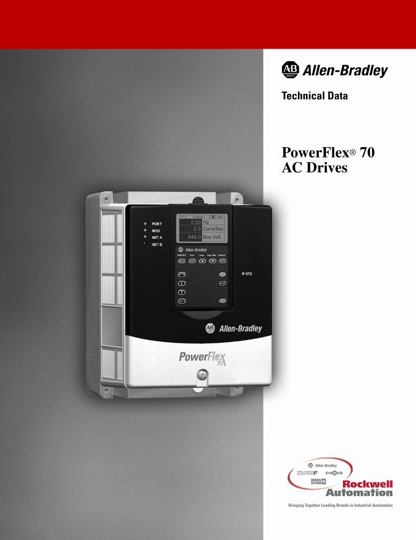
IP20, NEMA Type 1 – For conventional mounting inside or outside a control cabinet. Conduit plate is vertically removable for easy installation and replacement without disturbing conduit.
IP66, NEMA Type 4X/12 (Indoor Use) – For mounting directly in the production environment. Listed by UL to resist dust, dirt, etc. and to survive high pressure water spray. Also certified by NSF to assure conformity with international food equipment standards.
Flange Type – For mounting heatsink through back of an enclosure, thus removing a large portion of the heat inside a cabinet. The backside is rated IP66 and UL (NEMA) Type 4X/12 for both indoor and outdoor use.
Space Saving Hardware Features
Zero Stacking� - Drives can be mounted directly next to one another with no reduction of ambient temperature rating (50° C).
Integral EMC Filtering provides a compact, all-in-one package solution for meeting EMC requirements, including CE in Europe.
Integral Dynamic Brake Transistor delivers a cost-effective means of switching regenerative energy without costly external chopper circuits.
Internal Dynamic Brake Resistor requires no extra panel space, and supplies a large amount of braking torque for short periods.
Easy to Use Human Interface Tools
PowerFlex 7-Class LCD Human Interface Modules provide:
• Large and easy to read 7 line backlit display
• Variety of languages (English, French, German, Italian, Spanish, Portuguese, Dutch)
• Alternate function keys for shortcuts to common tasks
• “Calculator-like” number pad for fast and easy data entry (Full Numeric version only)
• Control keys for local start, stop, speed, and direction
• Remote versions for panel mount applications
Family of PC based configuration tools:
• DriveExplorer and DriveExplorer Lite: A simple and flexible “On-line” tool for monitoring and configuration while connected to a drive.
• DriveTools™ SP: A suite of software tools which provide an intuitive means for programming, troubleshooting and maintaining Allen-Bradley AC and DC drives.
3
Product Overview
Control and Performance Features
Vector Control with Force Technology ➊ provides outstanding torque and speed regulation, with or without encoder feedback.
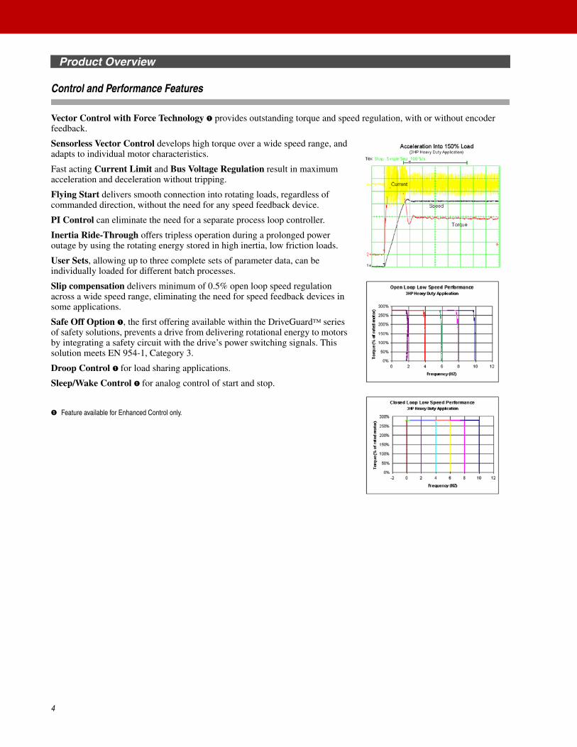
Sensorless Vector Control develops high torque over a wide speed range, and adapts to individual motor characteristics.
Fast acting Current Limit and Bus Voltage Regulation result in maximum acceleration and deceleration without tripping.
Flying Start delivers smooth connection into rotating loads, regardless of commanded direction, without the need for any speed feedback device.
PI Control can eliminate the need for a separate process loop controller.
Inertia Ride-Through offers tripless operation during a prolonged power outage by using the rotating energy stored in high inertia, low friction loads.
User Sets, allowing up to three complete sets of parameter data, can be individually loaded for different batch processes.
Slip compensation delivers minimum of 0.5% open loop speed regulation across a wide speed range, eliminating the need for speed feedback devices in some applications.
Safe Off Option ➊, the first offering available within the DriveGuard™ series of safety solutions, prevents a drive from delivering rotational energy to motors by integrating a safety circuit with the drive’s power switching signals. This solution meets EN 954-1, Category 3.
Droop Control ➊ for load sharing applications.
Sleep/Wake Control ➊ for analog control of start and stop.
➊ Feature available for Enhanced Control only.
4
Product Overview
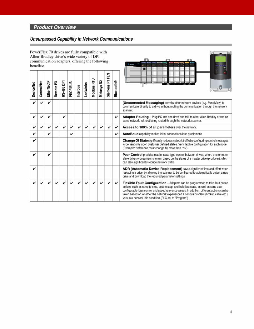
Unsurpassed Capability in Network Communications
PowerFlex 70 drives are fully compatible with Allen-Bradley drive’s wide variety of DPI communication adapters, offering the following benefits:
Devi
ceNe
t
Cont
rolN
et
Ethe
rNet
/IP
Rem
ote
I/O
RS-4
85 D
F1
PRO
FIBU
S
Inte
rbus
LonW
orks
Mod
bus
RTU
Met
asys
N2
Siem
ens
P1 F
LN
Blue
toot
h®
✔ ✔ ✔ (Unconnected Messaging) permits other network devices (e.g. PanelView) to communicate directly to a drive without routing the communication through the network scanner.
✔ ✔ ✔ ✔ ✔ Adapter Routing -- Plug PC into one drive and talk to other Allen-Bradley drives on same network, without being routed through the network scanner.
✔ ✔ ✔ ✔ ✔ ✔ ✔ ✔ ✔ ✔ ✔ ✔ Access to 100% of all parameters over the network.
✔ ✔ ✔ ✔ AutoBaud capability makes initial connections less problematic.
✔ Change Of State significantly reduces network traffic by configuring control messages to be sent only upon customer defined states. Very flexible configuration for each node (Example: “reference must change by more than 5%”).
✔ ✔ Peer Control provides master slave type control between drives, where one or more slave drives (consumers) can run based on the status of a master drive (producer), which can also significantly reduce network traffic.
✔ ADR (Automatic Device Replacement) saves significant time and effort when replacing a drive, by allowing the scanner to be configured to automatically detect a new drive and download the required parameter settings.
✔ ✔ ✔ ✔ ✔ ✔ ✔ ✔ ✔ ✔ ✔ ✔ Flexible Fault Configuration – Adapters can be programmed to take fault based actions such as ramp to stop, cost to stop, and hold last state, as well as send user configurable logic control and speed reference values. In addition, different actions can be taken based on whether the network experienced a serious problem (broken cable etc.) versus a network idle condition (PLC set to “Program”).
Esc Sel
Jog
Alt
5
Product Selection Guide
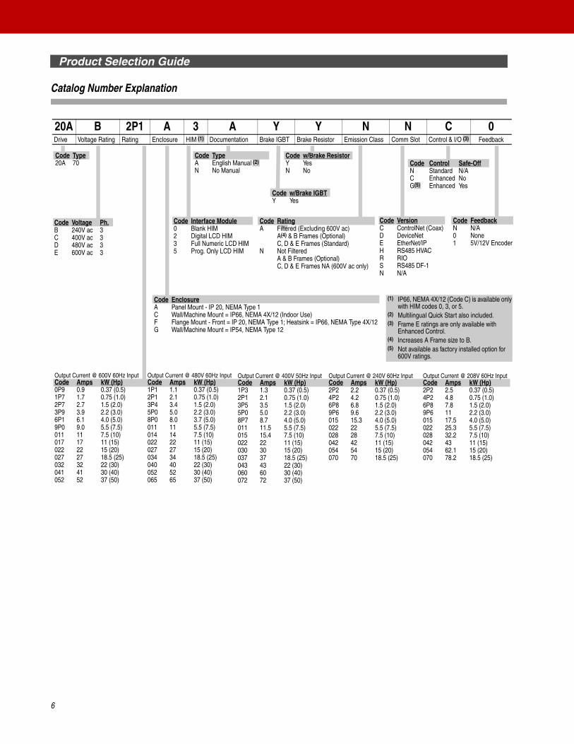
Catalog Number Explanation
Code Voltage Ph.B 240V ac 3C 400V ac 3D 480V ac 3E 600V ac 3
Code VersionC ControlNet (Coax)D DeviceNetE EtherNet/IPH RS485 HVACR RIOS RS485 DF-1N N/A
Code Interface Module0 Blank HIM2 Digital LCD HIM3 Full Numeric LCD HIM5 Prog. Only LCD HIM
Code w/Brake ResistorY YesN No
Code EnclosureA Panel Mount - IP 20, NEMA Type 1C Wall/Machine Mount = IP66, NEMA 4X/12 (Indoor Use)F Flange Mount - Front = IP 20, NEMA Type 1; Heatsink = IP66, NEMA Type 4X/12G Wall/Machine Mount = IP54, NEMA Type 12
Code w/Brake IGBTY Yes
20A B 2P1 A 3 A Y Y N N C 0Drive Voltage Rating Rating Enclosure HIM (1) Documentation Brake IGBT Brake Resistor Emission Class Comm Slot Control & I/O (3) Feedback
Output Current @ 480V 60Hz InputCode Amps kW (Hp)1P1 1.1 0.37 (0.5)2P1 2.1 0.75 (1.0)3P4 3.4 1.5 (2.0)5P0 5.0 2.2 (3.0)8P0 8.0 3.7 (5.0)011 11 5.5 (7.5)014 14 7.5 (10)022 22 11 (15)027 27 15 (20)034 34 18.5 (25)040 40 22 (30)052 52 30 (40)065 65 37 (50)
Code TypeA English Manual (2)
N No Manual
Code RatingA Filtered (Excluding 600V ac)
A(4) & B Frames (Optional)C, D & E Frames (Standard)
N Not FilteredA & B Frames (Optional)C, D & E Frames NA (600V ac only)
Output Current @ 240V 60Hz InputCode Amps kW (Hp)2P2 2.2 0.37 (0.5)4P2 4.2 0.75 (1.0)6P8 6.8 1.5 (2.0)9P6 9.6 2.2 (3.0)015 15.3 4.0 (5.0)022 22 5.5 (7.5)028 28 7.5 (10)042 42 11 (15)054 54 15 (20)070 70 18.5 (25)
Output Current @ 400V 50Hz InputCode Amps kW (Hp)1P3 1.3 0.37 (0.5)2P1 2.1 0.75 (1.0)3P5 3.5 1.5 (2.0)5P0 5.0 2.2 (3.0)8P7 8.7 4.0 (5.0)011 11.5 5.5 (7.5)015 15.4 7.5 (10)022 22 11 (15)030 30 15 (20)037 37 18.5 (25)043 43 22 (30)060 60 30 (40)072 72 37 (50)
Output Current @ 208V 60Hz InputCode Amps kW (Hp)2P2 2.5 0.37 (0.5)4P2 4.8 0.75 (1.0)6P8 7.8 1.5 (2.0)9P6 11 2.2 (3.0)015 17.5 4.0 (5.0)022 25.3 5.5 (7.5)028 32.2 7.5 (10)042 43 11 (15)054 62.1 15 (20)070 78.2 18.5 (25)
Output Current @ 600V 60Hz InputCode Amps kW (Hp)0P9 0.9 0.37 (0.5)1P7 1.7 0.75 (1.0)2P7 2.7 1.5 (2.0)3P9 3.9 2.2 (3.0)6P1 6.1 4.0 (5.0)9P0 9.0 5.5 (7.5)011 11 7.5 (10)017 17 11 (15)022 22 15 (20)027 27 18.5 (25)032 32 22 (30)041 41 30 (40)052 52 37 (50)
Code Type20A 70
(1) IP66, NEMA 4X/12 (Code C) is available only with HIM codes 0, 3, or 5.
(2) Multilingual Quick Start also included.(3) Frame E ratings are only available with
Enhanced Control.(4) Increases A Frame size to B.(5) Not available as factory installed option for
600V ratings.
Code Control Safe-OffN Standard N/AC Enhanced NoG(5) Enhanced Yes
Code FeedbackN N/A0 None1 5V/12V Encoder
6
Product Selection Guide
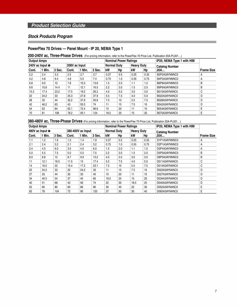
Stock Products Program
PowerFlex 70 Drives — Panel Mount - IP 20, NEMA Type 1
200-240V ac, Three-Phase Drives (For pricing information, refer to the PowerFlex 70 Price List, Publication 20A-PL001…)
380-480V ac, Three-Phase Drives (For pricing information, refer to the PowerFlex 70 Price List, Publication 20A-PL001…)
Output Amps Nominal Power Ratings IP20, NEMA Type 1 with HIM
Frame Size240V ac Input ➊ 208V ac Input Normal Duty Heavy Duty Catalog Number
20A…Cont. 1 Min. 3 Sec. Cont. 1 Min. 3 Sec. kW Hp kW Hp2.2 2.4 3.3 2.5 2.7 3.7 0.37 0.5 0.25 0.33 B2P2A3AYNNNC0 A4.2 4.8 6.4 4.8 5.5 7.4 0.75 1.0 0.55 0.75 B4P2A3AYNNNC0 A6.8 9.0 12 7.8 10.3 13.8 1.5 2.0 1.1 1.5 B6P8A3AYNNNC0 B9.6 10.6 14.4 11 12.1 16.5 2.2 3.0 1.5 2.0 B9P6A3AYNNNC0 B15.3 17.4 23.2 17.5 19.2 26.2 4.0 5.0 3.0 3.0 B015A3AYNANC0 C22 24.2 33 25.3 27.8 37.9 5.5 7.5 4.0 5.0 B022A3AYNANC0 D28 33 44 32.2 37.9 50.6 7.5 10 5.5 7.5 B028A3AYNANC0 D42 46.2 63 43 55.5 74 11 15 7.5 10 B042A3AYNANC0 D54 63 84 62.1 72.4 96.6 15 20 11 15 B054A3AYNANC0 E70 81 108 78.2 93.1 124 18.5 25 15 20 B070A3AYNANC0 E
Output Amps Nominal Power Ratings IP20, NEMA Type 1 with HIM
Frame Size480V ac Input ➊ 380-400V ac Input Normal Duty Heavy Duty Catalog Number
20A…Cont. 1 Min. 3 Sec. Cont. 1 Min. 3 Sec. kW Hp kW Hp1.1 1.2 1.6 1.3 1.4 1.9 0.37 0.5 0.25 0.33 D1P1A3AYNNNC0 A2.1 2.4 3.2 2.1 2.4 3.2 0.75 1.0 0.55 0.75 D2P1A3AYNNNC0 A3.4 4.5 6.0 3.5 4.5 6.0 1.5 2.0 1.1 1.5 D3P4A3AYNNNC0 A5.0 5.5 7.5 5.0 5.5 7.5 2.2 3.0 1.5 2.0 D5P0A3AYNNNC0 B8.0 8.8 12 8.7 9.9 13.2 4.0 5.0 3.0 3.0 D8P0A3AYNNNC0 B11 12.1 16.5 11.5 13 17.4 5.5 7.5 4.0 5.0 D011A3AYNANC0 C14 16.5 22 15.4 17.2 23.1 7.5 10 5.5 7.5 D014A3AYNANC0 C22 24.2 33 22 24.2 33 11 15 7.5 10 D022A3AYNANC0 D27 33 44 30 33 45 15 20 11 15 D027A3AYNANC0 D34 40.5 54 37 45 60 18.5 25 15 20 D034A3AYNANC0 D40 51 68 43 56 74 22 30 18.5 25 D040A3AYNANC0 D52 60 80 60 66 90 30 40 22 30 D052A3AYNANC0 E65 78 104 72 90 120 37 50 30 40 D065A3AYNANC0 E
7

Product Selection Guide
8
Standard Drives Selection
PowerFlex 70 Drives — Panel Mount - IP 20, NEMA Type 1
200-240V ac, Three-Phase Drives (For pricing information, refer to the PowerFlex 70 Price List, Publication 20A-PL001…)
380-480V ac, Three-Phase Drives (For pricing information, refer to the PowerFlex 70 Price List, Publication 20A-PL001…)
500-600V ac, Three-Phase Drives (For pricing information, refer to the PowerFlex 70 Price List, Publication 20A-PL001…)
➊ Catalog code corresponds to output amps in these columns. Drive must be programmed to lower voltage to obtain higher currents shown at right.
Output Amps Nominal Power Ratings IP20, NEMA Type 1 with HIM
Frame Size240V ac Input ➊ 208V ac Input Normal Duty Heavy Duty Catalog Number
20A…Cont. 1 Min. 3 Sec. Cont. 1 Min. 3 Sec. kW Hp kW Hp2.2 2.4 3.3 2.5 2.7 3.7 0.37 0.5 0.25 0.33 B2P2A0AYNNNC0 A4.2 4.8 6.4 4.8 5.5 7.4 0.75 1.0 0.55 0.75 B4P2A0AYNNNC0 A6.8 9.0 12 7.8 10.3 13.8 1.5 2.0 1.1 1.5 B6P8A0AYNNNC0 B9.6 10.6 14.4 11 12.1 16.5 2.2 3.0 1.5 2.0 B9P6A0AYNNNC0 B15.3 17.4 23.2 17.5 19.2 26.2 4.0 5.0 3.0 3.0 B015A0AYNANC0 C22 24.2 33 25.3 27.8 37.9 5.5 7.5 4.0 5.0 B022A0AYNANC0 D28 33 44 32.2 37.9 50.6 7.5 10 5.5 7.5 B028A0AYNANC0 D42 46.2 63 43 55.5 74 11 15 7.5 10 B042A0AYNANC0 D54 63 84 62.1 72.4 96.6 15 20 11 15 B054A0AYNANC0 E70 81 108 78.2 93.1 124 18.5 25 15 20 B070A0AYNANC0 E
Output Amps Nominal Power Ratings IP20, NEMA Type 1 with HIM
Frame Size480V ac Input ➊ 380-400V ac Input Normal Duty Heavy Duty Catalog Number
20A…Cont. 1 Min. 3 Sec. Cont. 1 Min. 3 Sec. kW Hp kW Hp1.1 1.2 1.6 1.3 1.4 1.9 0.37 0.5 0.25 0.33 D1P1A0AYNNNC0 A2.1 2.4 3.2 2.1 2.4 3.2 0.75 1.0 0.55 0.75 D2P1A0AYNNNC0 A3.4 4.5 6.0 3.5 4.5 6.0 1.5 2.0 1.1 1.5 D3P4A0AYNNNC0 A5.0 5.5 7.5 5.0 5.5 7.5 2.2 3.0 1.5 2.0 D5P0A0AYNNNC0 B8.0 8.8 12 8.7 9.9 13.2 4.0 5.0 3.0 3.0 D8P0A0AYNNNC0 B11 12.1 16.5 11.5 13 17.4 5.5 7.5 4.0 5.0 D011A0AYNANC0 C14 16.5 22 15.4 17.2 23.1 7.5 10 5.5 7.5 D014A0AYNANC0 C22 24.2 33 22 24.2 33 11 15 7.5 10 D022A0AYNANC0 D27 33 44 30 33 45 15 20 11 15 D027A0AYNANC0 D34 40.5 54 37 45 60 18.5 25 15 20 D034A0AYNANC0 D40 51 68 43 56 74 22 30 18.5 25 D040A0AYNANC0 D52 60 80 60 66 90 30 40 22 30 D052A0AYNANC0 E65 78 104 72 90 120 37 50 30 40 D065A0AYNANC0 E
Output Amps Nominal Power Ratings IP20, NEMA Type 1 with HIM
Frame Size600V ac Input Normal Duty Heavy Duty Catalog Number
20A…Cont. 1 Min. 3 Sec. kW Hp kW Hp0.9 1.0 1.4 0.37 0.5 0.25 0.33 E0P9A0AYNNNC0 A1.7 1.9 2.6 0.75 1.0 0.55 0.75 E1P7A0AYNNNC0 A2.7 3.6 4.8 1.5 2.0 1.1 1.0 E2P7A0AYNNNC0 A3.9 4.3 5.8 2.2 3.0 1.5 1.5 E3P9A0AYNNNC0 B6.1 6.7 9.1 4.0 5.0 3.0 3.0 E6P1A0AYNNNC0 B9.0 9.9 13.5 5.5 7.5 4.0 5.0 E9P0A0AYNNNC0 C11 13.5 18 7.5 10 5.5 7.5 E011A0AYNNNC0 C17 18.7 25.5 11 15 7.5 10 E017A0AYNNNC0 D22 25.5 34 15 20 11 15 E022A0AYNNNC0 D27 33 44 18.5 25 15 20 E027A0AYNNNC0 D32 40.5 54 22 30 18.5 25 E032A0AYNNNC0 D41 48 64 30 40 22 30 E041A0AYNANC0 E52 61.5 82 37 50 30 40 E052A0AYNANC0 E

Product Selection Guide
9
PowerFlex 70 Drives — Wall / Machine Mount - IP 66, NEMA Type 4X/12 (Indoor Use)
200-240V ac, Three-Phase Drives (For pricing information, refer to the PowerFlex 70 Price List, Publication 20A-PL001…)
380-480V ac, Three-Phase Drives (For pricing information, refer to the PowerFlex 70 Price List, Publication 20A-PL001…)
500-600V ac, Three-Phase Drives (For pricing information, refer to the PowerFlex 70 Price List, Publication 20A-PL001…)
➊ Catalog code corresponds to output amps in these columns. Drive must be programmed to lower voltage to obtain higher currents shown at right.
➋ Frame E ratings are only available with Enhanced Control.
Output Amps Nominal Power Ratings IP66, NEMA Type 4X/12 with HIM
Frame Size
240V ac Input ➊ 208V ac Input Normal Duty Heavy Duty Catalog Number 20A…Cont. 1 Min. 3 Sec. Cont. 1 Min. 3 Sec. kW Hp kW Hp
2.2 2.4 3.3 2.5 2.7 3.7 0.37 0.5 0.25 0.33 B2P2C3AYNNNC0 B4.2 4.8 6.4 4.8 5.5 7.4 0.75 1.0 0.55 0.75 B4P2C3AYNNNC0 B6.8 9.0 12 7.8 10.3 13.8 1.5 2.0 1.1 1.5 B6P8C3AYNNNC0 B9.6 10.6 14.4 11 12.1 16.5 2.2 3.0 1.5 2.0 B9P6C3AYNNNC0 B15.3 17.4 23.2 17.5 19.2 26.2 4.0 5.0 3.0 3.0 B015C3AYNANC0 D22 24.2 33 25.3 27.8 37.9 5.5 7.5 4.0 5.0 B022C3AYNANC0 D28 33 44 32.2 37.9 50.6 7.5 10 5.5 7.5 B028C3AYNANC0 D42 46.2 63 42 55.5 74 11 15 7.5 10 B042C3AYNANC0 D54 63 84 62.1 72.4 96.6 15 20 11 15 B054C3AYNANC0 E70 81 108 78.2 93.1 124 18.5 25 15 20 B070C3AYNANC0 E
Output Amps Nominal Power Ratings IP66, NEMA Type 4X/12 with HIM
Frame Size
480V ac Input ➊ 380-400V ac Input Normal Duty Heavy Duty Catalog Number 20A…Cont. 1 Min. 3 Sec. Cont. 1 Min. 3 Sec. kW Hp kW Hp
1.1 1.2 1.6 1.3 1.4 1.9 0.37 0.5 0.25 0.33 D1P1C3AYNNNC0 B2.1 2.4 3.2 2.1 2.4 3.2 0.75 1.0 0.55 0.75 D2P1C3AYNNNC0 B3.4 4.5 6.0 3.5 4.5 6.0 1.5 2.0 1.1 1.5 D3P4C3AYNNNC0 B5.0 5.5 7.5 5.0 5.5 7.5 2.2 3.0 1.5 2.0 D5P0C3AYNNNC0 B8.0 8.8 12 8.7 9.9 13.2 4.0 5.0 3.0 3.0 D8P0C3AYNNNC0 B11 12.1 16.5 11.5 13 17.4 5.5 7.5 4.0 5.0 D011C3AYNANC0 D14 16.5 22 15.4 17.2 23.1 7.5 10 5.5 7.5 D014C3AYNANC0 D22 24.2 33 22 24.2 33 11 15 7.5 10 D022C3AYNANC0 D27 33 44 30 33 45 15 20 11 15 D027C3AYNANC0 D34 40.5 54 37 45 60 18.5 25 15 20 D034C3AYNANC0 D40 51 68 43 56 74 22 30 18.5 25 D040C3AYNANC0 D52 60 80 60 66 90 30 40 22 30 D052C3AYNANC0 ➋ E65 78 104 72 90 120 37 50 30 40 D065C3AYNANC0 ➋ E
Output Amps Nominal Power Ratings IP66/NEMA Type 4X/12 with HIM
Frame Size
600V ac Input Normal Duty Heavy Duty Catalog Number 20A…Cont. 1 Min. 3 Sec. kW Hp kW Hp
0.9 1.0 1.4 0.37 0.5 0.25 0.33 E0P9C3AYNNNC0 B1.7 1.9 2.6 0.75 1.0 0.55 0.75 E1P7C3AYNNNC0 B2.7 3.6 4.8 1.5 2.0 1.1 1.0 E2P7C3AYNNNC0 B3.9 4.3 5.8 2.2 3.0 1.5 1.5 E3P9C3AYNNNC0 B6.1 6.7 9.1 4.0 5.0 3.0 3.0 E6P1C3AYNNNC0 B9.0 9.9 13.5 5.5 7.5 4.0 5.0 E9P0C3AYNNNC0 D11 13.5 18 7.5 10 5.5 7.5 E011C3AYNNNC0 D17 18.7 25.5 11 15 7.5 10 E017C3AYNNNC0 D22 25.5 34 15 20 11 15 E022C3AYNNNC0 D27 33 44 18.5 25 15 20 E027C3AYNNNC0 D32 40.5 54 22 30 18.5 25 E032C3AYNNNC0 D41 48 64 30 40 22 30 E041C3AYNANC0 E52 61.5 82 37 50 30 40 E052C3AYNANC0 E

Product Selection Guide
10
PowerFlex 70 Drives — Wall / Machine Mount - IP 54, NEMA Type 12
200-240V ac, Three-Phase Drives (For pricing information, refer to the PowerFlex 70 Price List, Publication 20A-PL001…)
380-480V ac, Three-Phase Drives (For pricing information, refer to the PowerFlex 70 Price List, Publication 20A-PL001…)
500-600V ac, Three-Phase Drives (For pricing information, refer to the PowerFlex 70 Price List, Publication 20A-PL001…)
Output Amps Nominal Power Ratings IP66, NEMA Type 4X/12 with HIM
Frame Size
240V ac Input ➊ 208V ac Input Normal Duty Heavy Duty Catalog Number 20A…Cont. 1 Min. 3 Sec. Cont. 1 Min. 3 Sec. kW Hp kW Hp
54 63 84 62.1 72.4 96.6 15 20 11 15 B054G3AYNANC0 E70 81 108 78.2 93.1 124 18.5 25 15 20 B070G3AYNANC0 E
Output Amps Nominal Power Ratings IP66, NEMA Type 4X/12 with HIM
Frame Size
480V ac Input ➊ 380-400V ac Input Normal Duty Heavy Duty Catalog Number 20A…Cont. 1 Min. 3 Sec. Cont. 1 Min. 3 Sec. kW Hp kW Hp
52 60 80 60 66 90 30 40 22 30 D052G3AYNANC0 E65 78 104 72 90 120 37 50 30 40 D065G3AYNANC0 E
Output Amps Nominal Power Ratings IP66, NEMA Type 4X/12 with HIM
Frame Size
600V ac Input ➊ 500-600V ac Input Normal Duty Heavy Duty Catalog Number 20A…Cont. 1 Min. 3 Sec. Cont. 1 Min. 3 Sec. kW Hp kW Hp
41 48 64 41 48 64 30 40 22 30 E041G3AYNANC0 E52 61.5 82 52 61.5 82 37 50 30 40 E052G3AYNANC0 E
Product Selection Guide
11
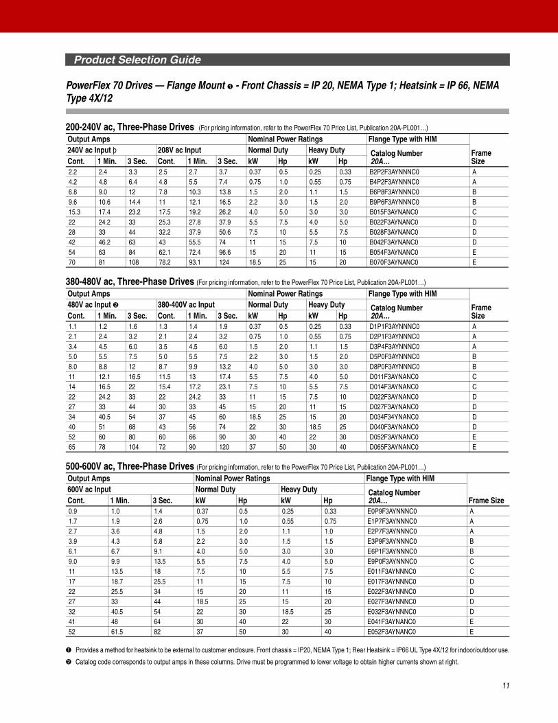
PowerFlex 70 Drives — Flange Mount ➊ - Front Chassis = IP 20, NEMA Type 1; Heatsink = IP 66, NEMA Type 4X/12
200-240V ac, Three-Phase Drives (For pricing information, refer to the PowerFlex 70 Price List, Publication 20A-PL001…)
380-480V ac, Three-Phase Drives (For pricing information, refer to the PowerFlex 70 Price List, Publication 20A-PL001…)
500-600V ac, Three-Phase Drives (For pricing information, refer to the PowerFlex 70 Price List, Publication 20A-PL001…)
➊ Provides a method for heatsink to be external to customer enclosure. Front chassis = IP20, NEMA Type 1; Rear Heatsink = IP66 UL Type 4X/12 for indoor/outdoor use.
➋ Catalog code corresponds to output amps in these columns. Drive must be programmed to lower voltage to obtain higher currents shown at right.
Output Amps Nominal Power Ratings Flange Type with HIM
Frame Size
240V ac Input þ 208V ac Input Normal Duty Heavy Duty Catalog Number20A…Cont. 1 Min. 3 Sec. Cont. 1 Min. 3 Sec. kW Hp kW Hp
2.2 2.4 3.3 2.5 2.7 3.7 0.37 0.5 0.25 0.33 B2P2F3AYNNNC0 A4.2 4.8 6.4 4.8 5.5 7.4 0.75 1.0 0.55 0.75 B4P2F3AYNNNC0 A6.8 9.0 12 7.8 10.3 13.8 1.5 2.0 1.1 1.5 B6P8F3AYNNNC0 B9.6 10.6 14.4 11 12.1 16.5 2.2 3.0 1.5 2.0 B9P6F3AYNNNC0 B15.3 17.4 23.2 17.5 19.2 26.2 4.0 5.0 3.0 3.0 B015F3AYNANC0 C22 24.2 33 25.3 27.8 37.9 5.5 7.5 4.0 5.0 B022F3AYNANC0 D28 33 44 32.2 37.9 50.6 7.5 10 5.5 7.5 B028F3AYNANC0 D42 46.2 63 43 55.5 74 11 15 7.5 10 B042F3AYNANC0 D54 63 84 62.1 72.4 96.6 15 20 11 15 B054F3AYNANC0 E70 81 108 78.2 93.1 124 18.5 25 15 20 B070F3AYNANC0 E
Output Amps Nominal Power Ratings Flange Type with HIM
Frame Size
480V ac Input ➋ 380-400V ac Input Normal Duty Heavy Duty Catalog Number20A…Cont. 1 Min. 3 Sec. Cont. 1 Min. 3 Sec. kW Hp kW Hp
1.1 1.2 1.6 1.3 1.4 1.9 0.37 0.5 0.25 0.33 D1P1F3AYNNNC0 A2.1 2.4 3.2 2.1 2.4 3.2 0.75 1.0 0.55 0.75 D2P1F3AYNNNC0 A3.4 4.5 6.0 3.5 4.5 6.0 1.5 2.0 1.1 1.5 D3P4F3AYNNNC0 A5.0 5.5 7.5 5.0 5.5 7.5 2.2 3.0 1.5 2.0 D5P0F3AYNNNC0 B8.0 8.8 12 8.7 9.9 13.2 4.0 5.0 3.0 3.0 D8P0F3AYNNNC0 B11 12.1 16.5 11.5 13 17.4 5.5 7.5 4.0 5.0 D011F3AYNANC0 C14 16.5 22 15.4 17.2 23.1 7.5 10 5.5 7.5 D014F3AYNANC0 C22 24.2 33 22 24.2 33 11 15 7.5 10 D022F3AYNANC0 D27 33 44 30 33 45 15 20 11 15 D027F3AYNANC0 D34 40.5 54 37 45 60 18.5 25 15 20 D034F34YNANC0 D40 51 68 43 56 74 22 30 18.5 25 D040F3AYNANC0 D52 60 80 60 66 90 30 40 22 30 D052F3AYNANC0 E65 78 104 72 90 120 37 50 30 40 D065F3AYNANC0 E
Output Amps Nominal Power Ratings Flange Type with HIM
Frame Size600V ac Input Normal Duty Heavy Duty Catalog Number
20A…Cont. 1 Min. 3 Sec. kW Hp kW Hp0.9 1.0 1.4 0.37 0.5 0.25 0.33 E0P9F3AYNNNC0 A1.7 1.9 2.6 0.75 1.0 0.55 0.75 E1P7F3AYNNNC0 A2.7 3.6 4.8 1.5 2.0 1.1 1.0 E2P7F3AYNNNC0 A3.9 4.3 5.8 2.2 3.0 1.5 1.5 E3P9F3AYNNNC0 B6.1 6.7 9.1 4.0 5.0 3.0 3.0 E6P1F3AYNNNC0 B9.0 9.9 13.5 5.5 7.5 4.0 5.0 E9P0F3AYNNNC0 C11 13.5 18 7.5 10 5.5 7.5 E011F3AYNNNC0 C17 18.7 25.5 11 15 7.5 10 E017F3AYNNNC0 D22 25.5 34 15 20 11 15 E022F3AYNNNC0 D27 33 44 18.5 25 15 20 E027F3AYNNNC0 D32 40.5 54 22 30 18.5 25 E032F3AYNNNC0 D41 48 64 30 40 22 30 E041F3AYNANC0 E52 61.5 82 37 50 30 40 E052F3AYNANC0 E
Product Selection Guide
12
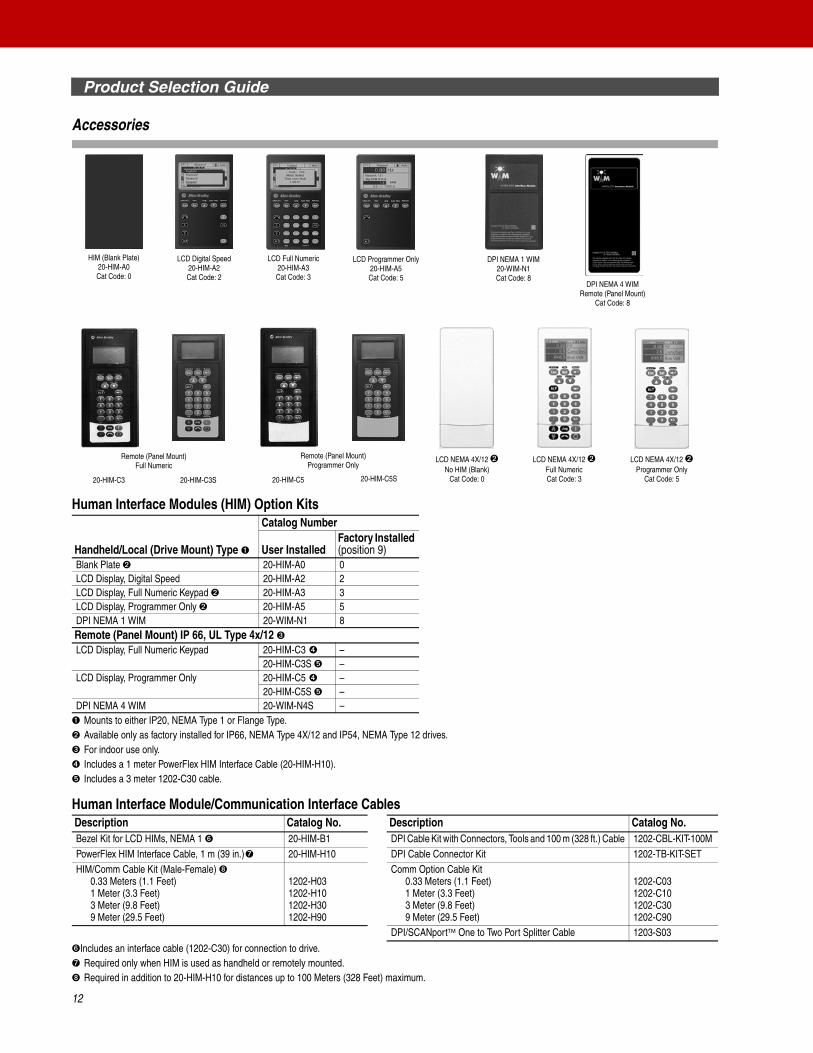
Accessories
Human Interface Modules (HIM) Option Kits
➊ Mounts to either IP20, NEMA Type 1 or Flange Type.➋ Available only as factory installed for IP66, NEMA Type 4X/12 and IP54, NEMA Type 12 drives.➌ For indoor use only.➍ Includes a 1 meter PowerFlex HIM Interface Cable (20-HIM-H10).➎ Includes a 3 meter 1202-C30 cable.
Human Interface Module/Communication Interface Cables
➏Includes an interface cable (1202-C30) for connection to drive.➐ Required only when HIM is used as handheld or remotely mounted.➑ Required in addition to 20-HIM-H10 for distances up to 100 Meters (328 Feet) maximum.
Handheld/Local (Drive Mount) Type ➊
Catalog Number
User InstalledFactory Installed (position 9)
Blank Plate ➋ 20-HIM-A0 0LCD Display, Digital Speed 20-HIM-A2 2LCD Display, Full Numeric Keypad ➋ 20-HIM-A3 3LCD Display, Programmer Only ➋ 20-HIM-A5 5DPI NEMA 1 WIM 20-WIM-N1 8Remote (Panel Mount) IP 66, UL Type 4x/12 ➌LCD Display, Full Numeric Keypad 20-HIM-C3 ➍ –
20-HIM-C3S ➎ –LCD Display, Programmer Only 20-HIM-C5 ➍ –
20-HIM-C5S ➎ –DPI NEMA 4 WIM 20-WIM-N4S –
Description Catalog No. Description Catalog No.Bezel Kit for LCD HIMs, NEMA 1 ➏ 20-HIM-B1 DPI Cable Kit with Connectors, Tools and 100 m (328 ft.) Cable 1202-CBL-KIT-100MPowerFlex HIM Interface Cable, 1 m (39 in.)➐ 20-HIM-H10 DPI Cable Connector Kit 1202-TB-KIT-SETHIM/Comm Cable Kit (Male-Female) ➑
0.33 Meters (1.1 Feet)1 Meter (3.3 Feet)3 Meter (9.8 Feet)9 Meter (29.5 Feet)
1202-H031202-H101202-H301202-H90
Comm Option Cable Kit 0.33 Meters (1.1 Feet)1 Meter (3.3 Feet)3 Meter (9.8 Feet)9 Meter (29.5 Feet)
1202-C031202-C101202-C301202-C90
DPI/SCANport One to Two Port Splitter Cable 1203-S03
LCD Digital Speed20-HIM-A2Cat Code: 2
LCD Full Numeric20-HIM-A3Cat Code: 3
HIM (Blank Plate)20-HIM-A0Cat Code: 0
LCD Programmer Only20-HIM-A5Cat Code: 5
20-HIM-C3 20-HIM-C3S 20-HIM-C5 20-HIM-C5S
Remote (Panel Mount)Full Numeric
Remote (Panel Mount)Programmer Only
LCD NEMA 4X/12 ➋No HIM (Blank)
Cat Code: 0
LCD NEMA 4X/12 ➋Full NumericCat Code: 3
LCD NEMA 4X/12 ➋Programmer Only
Cat Code: 5
DPI NEMA 4 WIMRemote (Panel Mount)
Cat Code: 8
DPI NEMA 1 WIM20-WIM-N1Cat Code: 8
Product Selection Guide
13
Accessories, Continued
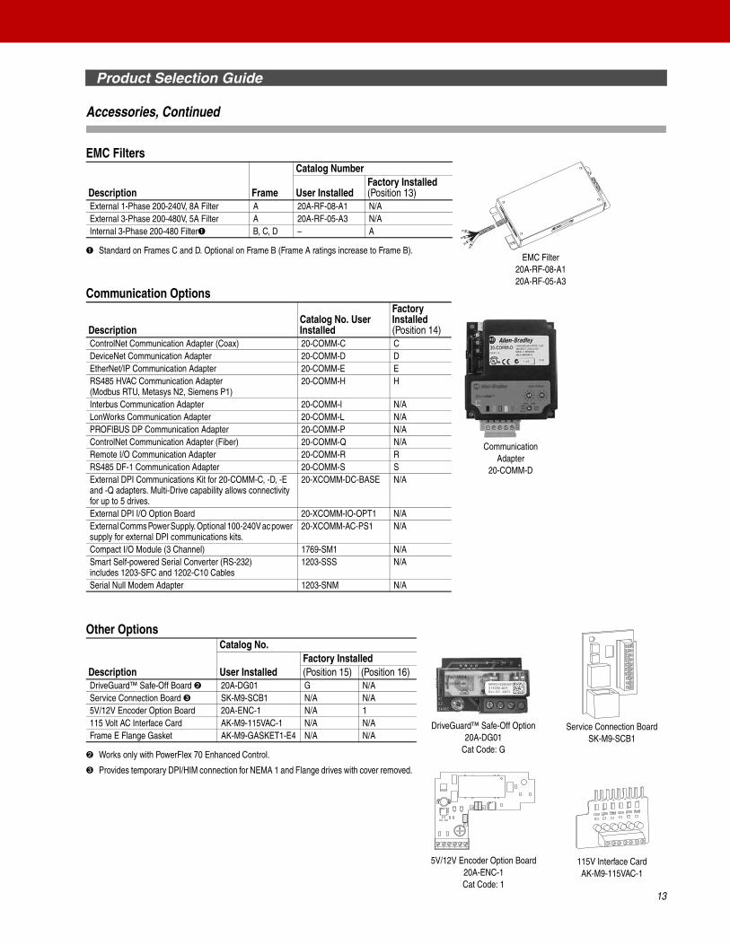
EMC Filters
➊ Standard on Frames C and D. Optional on Frame B (Frame A ratings increase to Frame B).
Communication Options
Other Options
➋ Works only with PowerFlex 70 Enhanced Control.
➌ Provides temporary DPI/HIM connection for NEMA 1 and Flange drives with cover removed.
Description Frame
Catalog Number
User InstalledFactory Installed (Position 13)
External 1-Phase 200-240V, 8A Filter A 20A-RF-08-A1 N/AExternal 3-Phase 200-480V, 5A Filter A 20A-RF-05-A3 N/AInternal 3-Phase 200-480 Filter➊ B, C, D – A
DescriptionCatalog No. User Installed
Factory Installed (Position 14)
ControlNet Communication Adapter (Coax) 20-COMM-C CDeviceNet Communication Adapter 20-COMM-D DEtherNet/IP Communication Adapter 20-COMM-E ERS485 HVAC Communication Adapter(Modbus RTU, Metasys N2, Siemens P1)
20-COMM-H H
Interbus Communication Adapter 20-COMM-I N/ALonWorks Communication Adapter 20-COMM-L N/APROFIBUS DP Communication Adapter 20-COMM-P N/AControlNet Communication Adapter (Fiber) 20-COMM-Q N/ARemote I/O Communication Adapter 20-COMM-R RRS485 DF-1 Communication Adapter 20-COMM-S SExternal DPI Communications Kit for 20-COMM-C, -D, -E and -Q adapters. Multi-Drive capability allows connectivity for up to 5 drives.
20-XCOMM-DC-BASE N/A
External DPI I/O Option Board 20-XCOMM-IO-OPT1 N/AExternal Comms Power Supply. Optional 100-240V ac power supply for external DPI communications kits.
20-XCOMM-AC-PS1 N/A
Compact I/O Module (3 Channel) 1769-SM1 N/ASmart Self-powered Serial Converter (RS-232)includes 1203-SFC and 1202-C10 Cables
1203-SSS N/A
Serial Null Modem Adapter 1203-SNM N/A
Description
Catalog No.
User InstalledFactory Installed(Position 15) (Position 16)
DriveGuard™ Safe-Off Board ➋ 20A-DG01 G N/AService Connection Board ➌ SK-M9-SCB1 N/A N/A5V/12V Encoder Option Board 20A-ENC-1 N/A 1115 Volt AC Interface Card AK-M9-115VAC-1 N/A N/AFrame E Flange Gasket AK-M9-GASKET1-E4 N/A N/A
CommunicationAdapter
20-COMM-D
EMC Filter20A-RF-08-A120A-RF-05-A3
Service Connection BoardSK-M9-SCB1
DriveGuard™ Safe-Off Option20A-DG01
Cat Code: G
1 2 3 4 5 6 7 8 9
1 2 3 4 5 6
115V Interface CardAK-M9-115VAC-1
5V/12V Encoder Option Board20A-ENC-1Cat Code: 1
Product Selection Guide
14
Accessories, Continued
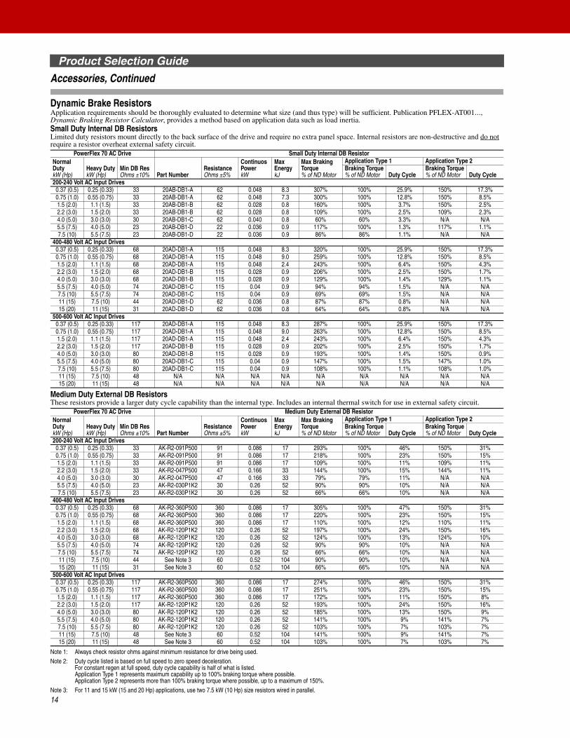
Dynamic Brake ResistorsApplication requirements should be thoroughly evaluated to determine what size (and thus type) will be sufficient. Publication PFLEX-AT001…, Dynamic Braking Resistor Calculator, provides a method based on application data such as load inertia.Small Duty Internal DB ResistorsLimited duty resistors mount directly to the back surface of the drive and require no extra panel space. Internal resistors are non-destructive and do not require a resistor overheat external safety circuit.
Medium Duty External DB ResistorsThese resistors provide a larger duty cycle capability than the internal type. Includes an internal thermal switch for use in external safety circuit.
Note 1: Always check resistor ohms against minimum resistance for drive being used.Note 2: Duty cycle listed is based on full speed to zero speed deceleration.
For constant regen at full speed, duty cycle capability is half of what is listed.Application Type 1 represents maximum capability up to 100% braking torque where possible.Application Type 2 represents more than 100% braking torque where possible, up to a maximum of 150%.
Note 3: For 11 and 15 kW (15 and 20 Hp) applications, use two 7.5 kW (10 Hp) size resistors wired in parallel.
PowerFlex 70 AC Drive Small Duty Internal DB ResistorNormal DutykW (Hp)
Heavy DutykW (Hp)
Min DB ResOhms ±10% Part Number
ResistanceOhms ±5%
Continuos PowerkW
Max EnergykJ
Max Braking Torque% of ND Motor
Application Type 1 Application Type 2Braking Torque% of ND Motor Duty Cycle
Braking Torque% of ND Motor Duty Cycle
200-240 Volt AC Input Drives0.37 (0.5) 0.25 (0.33) 33 20AB-DB1-A 62 0.048 8.3 307% 100% 25.9% 150% 17.3%0.75 (1.0) 0.55 (0.75) 33 20AB-DB1-A 62 0.048 7.3 300% 100% 12.8% 150% 8.5%1.5 (2.0) 1.1 (1.5) 33 20AB-DB1-B 62 0.028 0.8 160% 100% 3.7% 150% 2.5%2.2 (3.0) 1.5 (2.0) 33 20AB-DB1-B 62 0.028 0.8 109% 100% 2.5% 109% 2.3%4.0 (5.0) 3.0 (3.0) 30 20AB-DB1-C 62 0.040 0.8 60% 60% 3.3% N/A N/A5.5 (7.5) 4.0 (5.0) 23 20AB-DB1-D 22 0.036 0.9 117% 100% 1.3% 117% 1.1%7.5 (10) 5.5 (7.5) 23 20AB-DB1-D 22 0.036 0.9 86% 86% 1.1% N/A N/A
400-480 Volt AC Input Drives0.37 (0.5) 0.25 (0.33) 68 20AD-DB1-A 115 0.048 8.3 320% 100% 25.9% 150% 17.3%0.75 (1.0) 0.55 (0.75) 68 20AD-DB1-A 115 0.048 9.0 259% 100% 12.8% 150% 8.5%1.5 (2.0) 1.1 (1.5) 68 20AD-DB1-A 115 0.048 2.4 243% 100% 6.4% 150% 4.3%2.2 (3.0) 1.5 (2.0) 68 20AD-DB1-B 115 0.028 0.9 206% 100% 2.5% 150% 1.7%4.0 (5.0) 3.0 (3.0) 68 20AD-DB1-B 115 0.028 0.9 129% 100% 1.4% 129% 1.1%5.5 (7.5) 4.0 (5.0) 74 20AD-DB1-C 115 0.04 0.9 94% 94% 1.5% N/A N/A7.5 (10) 5.5 (7.5) 74 20AD-DB1-C 115 0.04 0.9 69% 69% 1.5% N/A N/A11 (15) 7.5 (10) 44 20AD-DB1-D 62 0.036 0.8 87% 87% 0.8% N/A N/A15 (20) 11 (15) 31 20AD-DB1-D 62 0.036 0.8 64% 64% 0.8% N/A N/A
500-600 Volt AC Input Drives0.37 (0.5) 0.25 (0.33) 117 20AD-DB1-A 115 0.048 8.3 287% 100% 25.9% 150% 17.3%0.75 (1.0) 0.55 (0.75) 117 20AD-DB1-A 115 0.048 9.0 263% 100% 12.8% 150% 8.5%1.5 (2.0) 1.1 (1.5) 117 20AD-DB1-A 115 0.048 2.4 243% 100% 6.4% 150% 4.3%2.2 (3.0) 1.5 (2.0) 117 20AD-DB1-B 115 0.028 0.9 202% 100% 2.5% 150% 1.7%4.0 (5.0) 3.0 (3.0) 80 20AD-DB1-B 115 0.028 0.9 193% 100% 1.4% 150% 0.9%5.5 (7.5) 4.0 (5.0) 80 20AD-DB1-C 115 0.04 0.9 147% 100% 1.5% 147% 1.0%7.5 (10) 5.5 (7.5) 80 20AD-DB1-C 115 0.04 0.9 108% 100% 1.1% 108% 1.0%11 (15) 7.5 (10) 48 N/A N/A N/A N/A N/A N/A N/A N/A N/A15 (20) 11 (15) 48 N/A N/A N/A N/A N/A N/A N/A N/A N/A
PowerFlex 70 AC Drive Medium Duty External DB ResistorNormal DutykW (Hp)
Heavy DutykW (Hp)
Min DB ResOhms ±10% Part Number
ResistanceOhms ±5%
Continuos PowerkW
Max EnergykJ
Max Braking Torque% of ND Motor
Application Type 1 Application Type 2Braking Torque% of ND Motor Duty Cycle
Braking Torque% of ND Motor Duty Cycle
200-240 Volt AC Input Drives0.37 (0.5) 0.25 (0.33) 33 AK-R2-091P500 91 0.086 17 293% 100% 46% 150% 31%0.75 (1.0) 0.55 (0.75) 33 AK-R2-091P500 91 0.086 17 218% 100% 23% 150% 15%1.5 (2.0) 1.1 (1.5) 33 AK-R2-091P500 91 0.086 17 109% 100% 11% 109% 11%2.2 (3.0) 1.5 (2.0) 33 AK-R2-047P500 47 0.166 33 144% 100% 15% 144% 11%4.0 (5.0) 3.0 (3.0) 30 AK-R2-047P500 47 0.166 33 79% 79% 11% N/A N/A5.5 (7.5) 4.0 (5.0) 23 AK-R2-030P1K2 30 0.26 52 90% 90% 10% N/A N/A7.5 (10) 5.5 (7.5) 23 AK-R2-030P1K2 30 0.26 52 66% 66% 10% N/A N/A
400-480 Volt AC Input Drives0.37 (0.5) 0.25 (0.33) 68 AK-R2-360P500 360 0.086 17 305% 100% 47% 150% 31%0.75 (1.0) 0.55 (0.75) 68 AK-R2-360P500 360 0.086 17 220% 100% 23% 150% 15%1.5 (2.0) 1.1 (1.5) 68 AK-R2-360P500 360 0.086 17 110% 100% 12% 110% 11%2.2 (3.0) 1.5 (2.0) 68 AK-R2-120P1K2 120 0.26 52 197% 100% 24% 150% 16%4.0 (5.0) 3.0 (3.0) 68 AK-R2-120P1K2 120 0.26 52 124% 100% 13% 124% 10%5.5 (7.5) 4.0 (5.0) 74 AK-R2-120P1K2 120 0.26 52 90% 90% 10% N/A N/A7.5 (10) 5.5 (7.5) 74 AK-R2-120P1K2 120 0.26 52 66% 66% 10% N/A N/A11 (15) 7.5 (10) 44 See Note 3 60 0.52 104 90% 90% 10% N/A N/A15 (20) 11 (15) 31 See Note 3 60 0.52 104 66% 66% 10% N/A N/A
500-600 Volt AC Input Drives0.37 (0.5) 0.25 (0.33) 117 AK-R2-360P500 360 0.086 17 274% 100% 46% 150% 31%0.75 (1.0) 0.55 (0.75) 117 AK-R2-360P500 360 0.086 17 251% 100% 23% 150% 15%1.5 (2.0) 1.1 (1.5) 117 AK-R2-360P500 360 0.086 17 172% 100% 11% 150% 8%2.2 (3.0) 1.5 (2.0) 117 AK-R2-120P1K2 120 0.26 52 193% 100% 24% 150% 16%4.0 (5.0) 3.0 (3.0) 80 AK-R2-120P1K2 120 0.26 52 185% 100% 13% 150% 9%5.5 (7.5) 4.0 (5.0) 80 AK-R2-120P1K2 120 0.26 52 141% 100% 9% 141% 7%7.5 (10) 5.5 (7.5) 80 AK-R2-120P1K2 120 0.26 52 103% 100% 7% 103% 7%11 (15) 7.5 (10) 48 See Note 3 60 0.52 104 141% 100% 9% 141% 7%15 (20) 11 (15) 48 See Note 3 60 0.52 104 103% 100% 7% 103% 7%
Product Selection Guide
15
Accessories, Continued
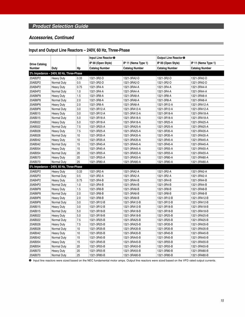
Input and Output Line Reactors – 240V, 60 Hz, Three-Phase
➊ Input line reactors were sized based on the NEC fundamental motor amps. Output line reactors were sized based on the VFD rated output currents.
Drive Catalog Number Duty Hp
Input Line Reactor➊ Output Line Reactor➊
IP 00 (Open Style) IP 11 (Nema Type 1) IP 00 (Open Style) IP 11 (Nema Type 1)
Catalog Number Catalog Number Catalog Number Catalog Number
3% Impedance – 240V, 60 Hz, Three-Phase
20AB2P2 Heavy Duty 0.33 1321-3R2-D 1321-3RA2-D 1321-3R2-D 1321-3RA2-D20AB2P2 Normal Duty 0.5 1321-3R2-D 1321-3RA2-D 1321-3R2-D 1321-3RA2-D20AB4P2 Heavy Duty 0.75 1321-3R4-A 1321-3RA4-A 1321-3R4-A 1321-3RA4-A20AB4P2 Normal Duty 1.0 1321-3R4-A 1321-3RA4-A 1321-3R4-A 1321-3RA4-A20AB6P8 Heavy Duty 1.5 1321-3R8-A 1321-3RA8-A 1321-3R8-A 1321-3RA8-A20AB6P8 Normal Duty 2.0 1321-3R8-A 1321-3RA8-A 1321-3R8-A 1321-3RA8-A20AB9P6 Heavy Duty 2.0 1321-3R8-A 1321-3RA8-A 1321-3R12-A 1321-3RA12-A20AB9P6 Normal Duty 3.0 1321-3R12-A 1321-3RA12-A 1321-3R12-A 1321-3RA12-A20AB015 Heavy Duty 3.0 1321-3R12-A 1321-3RA12-A 1321-3R18-A 1321-3RA18-A20AB015 Normal Duty 5.0 1321-3R18-A 1321-3RA18-A 1321-3R18-A 1321-3RA18-A20AB022 Heavy Duty 5.0 1321-3R18-A 1321-3RA18-A 1321-3R25-A 1321-3RA25-A20AB022 Normal Duty 7.5 1321-3R25-A 1321-3RA25-A 1321-3R25-A 1321-3RA25-A20AB028 Heavy Duty 7.5 1321-3R25-A 1321-3RA25-A 1321-3R35-A 1321-3RA35-A20AB028 Normal Duty 10 1321-3R35-A 1321-3RA35-A 1321-3R35-A 1321-3RA35-A20AB042 Heavy Duty 10 1321-3R35-A 1321-3RA35-A 1321-3R45-A 1321-3RA45-A20AB042 Normal Duty 15 1321-3R45-A 1321-3RA45-A 1321-3R45-A 1321-3RA45-A20AB054 Heavy Duty 15 1321-3R45-A 1321-3RA45-A 1321-3R55-A 1321-3RA55-A20AB054 Normal Duty 20 1321-3R55-A 1321-3RA55-A 1321-3R55-A 1321-3RA55-A20AB070 Heavy Duty 20 1321-3R55-A 1321-3RA55-A 1321-3R80-A 1321-3RA80-A20AB070 Normal Duty 25 1321-3R80-A 1321-3RA80-A 1321-3R80-A 1321-3RA80-A
5% Impedance – 240V, 60 Hz, Three-Phase
20AB2P2 Heavy Duty 0.33 1321-3R2-A 1321-3RA2-A 1321-3R2-A 1321-3RA2-A20AB2P2 Normal Duty 0.5 1321-3R2-A 1321-3RA2-A 1321-3R2-A 1321-3RA2-A20AB4P2 Heavy Duty 0.75 1321-3R4-B 1321-3RA4-B 1321-3R4-B 1321-3RA4-B20AB4P2 Normal Duty 1.0 1321-3R4-B 1321-3RA4-B 1321-3R4-B 1321-3RA4-B20AB6P8 Heavy Duty 1.5 1321-3R8-B 1321-3RA8-B 1321-3R8-B 1321-3RA8-B20AB6P8 Normal Duty 2.0 1321-3R8-B 1321-3RA8-B 1321-3R8-B 1321-3RA8-B20AB9P6 Heavy Duty 2.0 1321-3R8-B 1321-3RA8-B 1321-3R12-B 1321-3RA12-B20AB9P6 Normal Duty 3.0 1321-3R12-B 1321-3RA12-B 1321-3R12-B 1321-3RA12-B20AB015 Heavy Duty 3.0 1321-3R12-B 1321-3RA12-B 1321-3R18-B 1321-3RA18-B20AB015 Normal Duty 5.0 1321-3R18-B 1321-3RA18-B 1321-3R18-B 1321-3RA18-B20AB022 Heavy Duty 5.0 1321-3R18-B 1321-3RA18-B 1321-3R25-B 1321-3RA25-B20AB022 Normal Duty 7.5 1321-3R25-B 1321-3RA25-B 1321-3R25-B 1321-3RA25-B20AB028 Heavy Duty 7.5 1321-3R25-B 1321-3RA25-B 1321-3R35-B 1321-3RA35-B20AB028 Normal Duty 10 1321-3R35-B 1321-3RA35-B 1321-3R35-B 1321-3RA35-B20AB042 Heavy Duty 10 1321-3R35-B 1321-3RA35-B 1321-3R45-B 1321-3RA45-B20AB042 Normal Duty 15 1321-3R45-B 1321-3RA45-B 1321-3R45-B 1321-3RA45-B20AB054 Heavy Duty 15 1321-3R45-B 1321-3RA45-B 1321-3R55-B 1321-3RA55-B20AB054 Normal Duty 20 1321-3R55-B 1321-3RA55-B 1321-3R55-B 1321-3RA55-B20AB070 Heavy Duty 20 1321-3R55-B 1321-3RA55-B 1321-3R80-B 1321-3RA80-B20AB070 Normal Duty 25 1321-3R80-B 1321-3RA80-B 1321-3R80-B 1321-3RA80-B
Product Selection Guide
16
Accessories, Continued
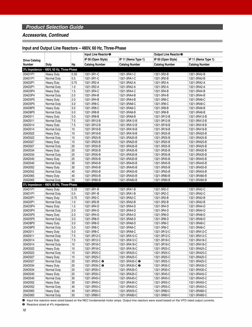
Input and Output Line Reactors – 480V, 60 Hz, Three-Phase
➊ Input line reactors were sized based on the NEC fundamental motor amps. Output line reactors were sized based on the VFD rated output currents.➋ Reactors sized at 4% impedance.
Drive Catalog Number Duty Hp
Input Line Reactor➊ Output Line Reactor➊
IP 00 (Open Style) IP 11 (Nema Type 1) IP 00 (Open Style) IP 11 (Nema Type 1)
Catalog Number Catalog Number Catalog Number Catalog Number
3% Impedance – 480V, 60 Hz, Three-Phase20AD1P1 Heavy Duty 0.33 1321-3R1-C 1321-3RA1-C 1321-3R2-B 1321-3RA2-B20AD1P1 Normal Duty 0.5 1321-3R1-C 1321-3RA1-C 1321-3R2-B 1321-3RA2-B20AD2P1 Heavy Duty 0.75 1321-3R2-A 1321-3RA2-A 1321-3R2-A 1321-3RA2-A20AD2P1 Normal Duty 1.0 1321-3R2-A 1321-3RA2-A 1321-3R2-A 1321-3RA2-A20AD3P4 Heavy Duty 1.5 1321-3R4-C 1321-3RA4-C 1321-3R4-B 1321-3RA4-B20AD3P4 Normal Duty 2.0 1321-3R4-B 1321-3RA4-B 1321-3R4-B 1321-3RA4-B20AD5P0 Heavy Duty 2.0 1321-3R4-B 1321-3RA4-B 1321-3R8-C 1321-3RA8-C20AD5P0 Normal Duty 3.0 1321-3R8-C 1321-3RA8-C 1321-3R8-C 1321-3RA8-C20AD8P0 Heavy Duty 3.0 1321-3R8-C 1321-3RA8-C 1321-3R8-B 1321-3RA8-B20AD8P0 Normal Duty 5.0 1321-3R8-B 1321-3RA8-B 1321-3R8-B 1321-3RA8-B20AD011 Heavy Duty 5.0 1321-3R8-B 1321-3RA8-B 1321-3R12-B 1321-3RA12-B20AD011 Normal Duty 7.5 1321-3R12-B 1321-3RA12-B 1321-3R12-B 1321-3RA12-B20AD014 Heavy Duty 7.5 1321-3R12-B 1321-3RA12-B 1321-3R18-B 1321-3RA18-B20AD014 Normal Duty 10 1321-3R18-B 1321-3RA18-B 1321-3R18-B 1321-3RA18-B20AD022 Heavy Duty 10 1321-3R18-B 1321-3RA18-B 1321-3R25-B 1321-3RA25-B20AD022 Normal Duty 15 1321-3R25-B 1321-3RA25-B 1321-3R25-B 1321-3RA25-B20AD027 Heavy Duty 15 1321-3R25-B 1321-3RA25-B 1321-3R25-B 1321-3RA25-B20AD027 Normal Duty 20 1321-3R35-B 1321-3RA35-B 1321-3R25-B 1321-3RA25-B20AD034 Heavy Duty 20 1321-3R35-B 1321-3RA35-B 1321-3R35-B 1321-3RA35-B20AD034 Normal Duty 25 1321-3R35-B 1321-3RA35-B 1321-3R35-B 1321-3RA35-B20AD040 Heavy Duty 25 1321-3R35-B 1321-3RA35-B 1321-3R45-B 1321-3RA45-B20AD040 Normal Duty 30 1321-3R45-B 1321-3RA45-B 1321-3R45-B 1321-3RA45-B20AD052 Heavy Duty 30 1321-3R45-B 1321-3RA45-B 1321-3R55-B 1321-3RA55-B20AD052 Normal Duty 40 1321-3R55-B 1321-3RA55-B 1321-3R55-B 1321-3RA55-B20AD065 Heavy Duty 40 1321-3R55-B 1321-3RA55-B 1321-3R80-B 1321-3RA80-B20AD065 Normal Duty 50 1321-3R80-B 1321-3RA80-B 1321-3R80-B 1321-3RA80-B5% Impedance – 480V, 60 Hz, Three-Phase20AD1P1 Heavy Duty 0.33 1321-3R1-B 1321-3RA1-B 1321-3R2-C 1321-3RA2-C20AD1P1 Normal Duty 0.5 1321-3R1-B 1321-3RA1-B 1321-3R2-C 1321-3RA2-C20AD2P1 Heavy Duty 0.75 1321-3R2-C 1321-3RA2-C 1321-3R2-B 1321-3RA2-B20AD2P1 Normal Duty 1.0 1321-3R2-B 1321-3RA2-B 1321-3R2-B 1321-3RA2-B20AD3P4 Heavy Duty 1.5 1321-3R4-D 1321-3RA4-D 1321-3R4-D 1321-3RA4-D20AD3P4 Normal Duty 2.0 1321-3R4-D 1321-3RA4-D 1321-3R4-D 1321-3RA4-D20AD5P0 Heavy Duty 2.0 1321-3R4-D 1321-3RA4-D 1321-3R8-D 1321-3RA8-D20AD5P0 Normal Duty 3.0 1321-3R8-D 1321-3RA8-D 1321-3R8-D 1321-3RA8-D20AD8P0 Heavy Duty 3.0 1321-3R8-D 1321-3RA8-D 1321-3R8-C 1321-3RA8-C20AD8P0 Normal Duty 5.0 1321-3R8-C 1321-3RA8-C 1321-3R8-C 1321-3RA8-C20AD011 Heavy Duty 5.0 1321-3R8-C 1321-3RA8-C 1321-3R12-C 1321-3RA12-C20AD011 Normal Duty 7.5 1321-3R12-C 1321-3RA12-C 1321-3R12-C 1321-3RA12-C20AD014 Heavy Duty 7.5 1321-3R12-C 1321-3RA12-C 1321-3R18-C 1321-3RA18-C20AD014 Normal Duty 10 1321-3R18-C 1321-3RA18-C 1321-3R18-C 1321-3RA18-C20AD022 Heavy Duty 10 1321-3R18-C 1321-3RA18-C 1321-3R25-C 1321-3RA25-C20AD022 Normal Duty 15 1321-3R25-C 1321-3RA25-C 1321-3R25-C 1321-3RA25-C20AD027 Heavy Duty 15 1321-3R25-C 1321-3RA25-C 1321-3R25-C 1321-3RA25-C20AD027 Normal Duty 20 1321-3R35-C ➋ 1321-3RA35-C ➋ 1321-3R25-C 1321-3RA25-C20AD034 Heavy Duty 20 1321-3R35-C ➋ 1321-3RA35-C ➋ 1321-3R35-C 1321-3RA35-C20AD034 Normal Duty 25 1321-3R35-C 1321-3RA35-C 1321-3R35-C 1321-3RA35-C20AD040 Heavy Duty 25 1321-3R35-C 1321-3RA35-C 1321-3R45-C 1321-3RA45-C20AD040 Normal Duty 30 1321-3R45-C 1321-3RA45-C 1321-3R45-C 1321-3RA45-C20AD052 Heavy Duty 30 1321-3R45-C 1321-3RA45-C 1321-3R55-C 1321-3RA55-C20AD052 Normal Duty 40 1321-3R55-C 1321-3RA55-C 1321-3R55-C 1321-3RA55-C20AD065 Heavy Duty 40 1321-3R55-C 1321-3RA55-C 1321-3R80-C 1321-3RA80-C20AD065 Normal Duty 50 1321-3R80-C 1321-3RA80-C 1321-3R80-C 1321-3RA80-C

Product Selection Guide
17
Accessories, Continued
Input and Output Line Reactors – 600V, 60 Hz, Three-Phase
➊ Input line reactors were sized based on the NEC fundamental motor amps. Output line reactors were sized based on the VFD rated output currents.➋ Reactors sized at 4% impedance.
Drive Catalog Number Duty Hp
Input Line Reactor➊ Output Line Reactor➊
IP 00 (Open Style) IP 11 (Nema Type 1) IP 00 (Open Style) IP 11 (Nema Type 1)
Catalog Number Catalog Number Catalog Number Catalog Number
3% Impedance – 480V, 60 Hz, Three-Phase20AE0P9 Heavy Duty 0.33 1321-3R1-C 1321-3RA1-C 1321-3R1-B 1321-3RA1-B20AE0P9 Normal Duty 0.5 1321-3R1-C 1321-3RA1-C 1321-3R1-B 1321-3RA1-B20AE1P7 Heavy Duty 0.75 1321-3R2-B 1321-3RA2-B 1321-3R2-B 1321-3RA2-B20AE1P7 Normal Duty 1.0 1321-3R2-B 1321-3RA2-B 1321-3R2-B 1321-3RA2-B20AE2P7 Heavy Duty 1.5 1321-3R2-A 1321-3RA2-A 1321-3R4-D 1321-3RA4-D20AE2P7 Normal Duty 2.0 1321-3R4-C 1321-3RA2-C 1321-3R4-D 1321-3RA4-D20AE3P9 Heavy Duty 2.0 1321-3R4-C 1321-3RA4-C 1321-3R4-C 1321-3RA4-C20AE3P9 Normal Duty 3.0 1321-3R4-C 1321-3RA4-C 1321-3R4-C 1321-3RA4-C20AE6P1 Heavy Duty 3.0 1321-3R4-C 1321-3RA4-C 1321-3R8-C 1321-3RA8-C20AE6P1 Normal Duty 5.0 1321-3R8-C 1321-3RA8-C 1321-3R8-C 1321-3RA8-C20AE9P0 Heavy Duty 5.0 1321-3R8-C 1321-3RA8-C 1321-3R12-C 1321-3RA12-C20AE9P0 Normal Duty 7.5 1321-3R12-C 1321-3RA12-C 1321-3R12-C 1321-3RA12-C20AE011 Heavy Duty 7.5 1321-3R12-C 1321-3RA12-C 1321-3R12-B 1321-3RA12-B20AE011 Normal Duty 10 1321-3R12-B 1321-3RA12-B 1321-3R12-B 1321-3RA12-B20AE017 Heavy Duty 10 1321-3R12-B 1321-3RA12-B 1321-3R18-C 1321-3RA18-C20AE017 Normal Duty 15 1321-3R18-B 1321-3RA18-B 1321-3R18-C 1321-3RA18-C20AE022 Heavy Duty 15 1321-3R18-B 1321-3RA18-B 1321-3R25-B 1321-3RA25-B20AE022 Normal Duty 20 1321-3R25-B 1321-3RA25-B 1321-3R25-B 1321-3RA25-B20AE027 Heavy Duty 20 1321-3R25-B 1321-3RA25-B 1321-3R35-C 1321-3RA35-C20AE027 Normal Duty 25 1321-3R35-C 1321-3RA35-C 1321-3R35-C 1321-3RA35-C20AE032 Heavy Duty 25 1321-3R35-C 1321-3RA35-C 1321-3R35-B 1321-3RA35-B20AE032 Normal Duty 30 1321-3R35-B 1321-3RA35-B 1321-3R35-B 1321-3RA35-B20AE041 Heavy Duty 30 1321-3R35-B 1321-3RA35-B 1321-3R45-B 1321-3RA45-B20AE041 Normal Duty 40 1321-3R45-B 1321-3RA45-B 1321-3R45-B 1321-3RA45-B20AE052 Heavy Duty 40 1321-3R45-B 1321-3RA45-B 1321-3R55-B 1321-3RA55-B20AE052 Normal Duty 50 1321-3R55-B 1321-3RA55-B 1321-3R55-B 1321-3RA55-B5% Impedance – 480V, 60 Hz, Three-Phase20AE0P9 Heavy Duty 0.33 1321-3R1-A 1321-3RA1-A 1321-3R1-B 1321-3RA1-B20AE0P9 Normal Duty 0.5 1321-3R1-B 1321-3RA1-B 1321-3R1-B 1321-3RA1-B20AE1P7 Heavy Duty 0.75 1321-3R2-C 1321-3RA2-C 1321-3R2-C 1321-3RA2-C20AE1P7 Normal Duty 1.0 1321-3R2-C 1321-3RA2-C 1321-3R2-C 1321-3RA2-C20AE2P7 Heavy Duty 1.5 1321-3R2-B 1321-3RA2-B 1321-3R4-D ➋ 1321-3RA4-D ➋20AE2P7 Normal Duty 2.0 1321-3R4-D ➋ 1321-3RA4-D ➋ 1321-3R4-D ➋ 1321-3RA4-D ➋20AE3P9 Heavy Duty 2.0 1321-3R4-D ➋ 1321-3RA4-D ➋ 1321-3R4-D 1321-3RA4-D20AE3P9 Normal Duty 3.0 1321-3R4-D 1321-3RA4-D 1321-3R4-D 1321-3RA4-D20AE6P1 Heavy Duty 3.0 1321-3R4-D 1321-3RA4-D 1321-3R8-D 1321-3RA8-D20AE6P1 Normal Duty 5.0 1321-3R8-D 1321-3RA8-D 1321-3R8-D 1321-3RA8-D20AE9P0 Heavy Duty 5.0 1321-3R8-D 1321-3RA8-D 1321-3R12-C ➋ 1321-3RA12-C ➋20AE9P0 Normal Duty 7.5 1321-3R12-C ➋ 1321-3RA12-C ➋ 1321-3R12-C ➋ 1321-3RA12-C ➋20AE011 Heavy Duty 7.5 1321-3R12-C ➋ 1321-3RA12-C ➋ 1321-3R12-C 1321-3RA12-C20AE011 Normal Duty 10 1321-3R12-C 1321-3RA12-C 1321-3R12-C 1321-3RA12-C20AE017 Heavy Duty 10 1321-3R12-C 1321-3RA12-C 1321-3R18-C 1321-3RA18-C20AE017 Normal Duty 15 1321-3R18-C 1321-3RA18-C 1321-3R18-C 1321-3RA18-C20AE022 Heavy Duty 15 1321-3R18-C 1321-3RA18-C 1321-3R25-C 1321-3RA25-C20AE022 Normal Duty 20 1321-3R25-C 1321-3RA25-C 1321-3R25-C 1321-3RA25-C20AE027 Heavy Duty 20 1321-3R25-C ➋ 1321-3RA25-C ➋ 1321-3R35-C ➋ 1321-3RA35-C ➋20AE027 Normal Duty 25 1321-3R35-C ➋ 1321-3RA35-C ➋ 1321-3R35-C ➋ 1321-3RA35-C ➋20AE032 Heavy Duty 25 1321-3R35-C ➋ 1321-3RA35-C ➋ 1321-3R35-C ➋ 1321-3RA35-C ➋20AE032 Normal Duty 30 1321-3R35-C ➋ 1321-3RA35-C ➋ 1321-3R35-C ➋ 1321-3RA35-C ➋20AE041 Heavy Duty 30 1321-3R35-C ➋ 1321-3RA35-C ➋ 1321-3R45-C 1321-3RA45-C20AE041 Normal Duty 40 1321-3R45-C 1321-3RA45-C 1321-3R45-C 1321-3RA45-C20AE052 Heavy Duty 40 1321-3R45-C 1321-3RA45-C 1321-3R55-C 1321-3RA55-C20AE052 Normal Duty 50 1321-3R55-C 1321-3RA55-C 1321-3R55-C 1321-3RA55-C
Packaged Drives Program
Packaged Drives Overview
The PowerFlex 70 Packaged Drives Program allows users to create drive packages based on their specific needs. This program enhances stand-a-lone drive functionality through additional control, power and packaging options which are ideal for OEM and end users with special installation needs.
The program has three levels:
Quick Ship
Quick Ship products are intended to meet faster than normal delivery requirements. Pre-defined catalog strings are offered to support shipping one to three business days from date of order entry. The current offering is based on NEMA 1 (IP20) and NEMA 4/12 (IP65), 480V, top of frame ratings for frames A-C and frame D @ 20 Hp. These packages are a subset of the Standard Packaged Drives Program noted below and can be ordered through the Passport order entry system. This program uses the Standard Control version of the PowerFlex 70.
Standard Packaged Drives
The Standard Packaged Drives Program allows users to create drive packages based on their specific needs. A complete drive package may be specified by assembling a single catalog number string that includes a base drive and all required options. Packaging is available for 480V requirements in NEMA Type 1 (IP20), NEMA 4/12 (IP65) indoor, andNEMA 3/4 (IP65) outdoor. The program consists of a fully defined catalog string identified within the price sheet. Focused on higher volume, repeat business, the standard designs provide consistent manufacturing and minimizes customer resources by reducing engineering, manufacturing and installation time. Typical delivery is 10 business days from order entry and can be ordered through the Passport order entry system. This program uses the Enhanced Control version of the PowerFlex 70.
Engineered Drives
The Engineered Drives Program offers users the ability to create drive packages beyond the Standard Packaged Drives offering. Packaging is available for 208V, 240V, 480V and 600V requirements. This program supports both the Standard and the Enhanced Control versions of the PowerFlex 70. Options may or may not be defined within this publication. Product can be ordered by:
• Assembling a catalog string from the options listed in this publication.Engineered options that are listed within this publication will be specified by the heading “Engineered Drives Program Only” and will have varied lead-times.
• Entering a custom quote request for additional options not listed.A custom quote will require a Passport quote using “SP-SDB-CUSTOM” as the line item part number and entering a description of the base catalog string and custom options in the Competitive Summary. For questions or help with a custom quote please contact the Engineered Drives Group at 262-512-8415.
18
Packaged Drives Program
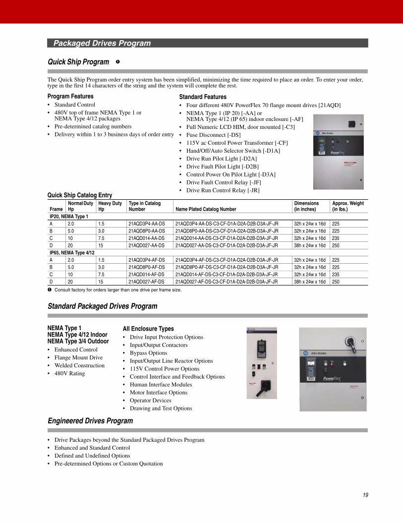
Quick Ship Program
The Quick Ship Program order entry system has been simplified, minimizing the time required to place an order. To enter your order, type in the first 14 characters of the string and the system will complete the rest.
Program Features• Standard Control• 480V top of frame NEMA Type 1 or
NEMA Type 4/12 packages• Pre-determined catalog numbers• Delivery within 1 to 3 business days of order entry
Quick Ship Catalog Entry
➊ Consult factory for orders larger than one drive per frame size.
Standard Packaged Drives Program
NEMA Type 1NEMA Type 4/12 IndoorNEMA Type 3/4 Outdoor• Enhanced Control• Flange Mount Drive• Welded Construction• 480V Rating
Engineered Drives Program
• Drive Packages beyond the Standard Packaged Drives Program• Enhanced and Standard Control• Defined and Undefined Options• Pre-determined Options or Custom Quotation
FrameNormal Duty Hp
Heavy Duty Hp
Type in Catalog Number Name Plated Catalog Number
Dimensions(in inches)
Approx. Weight (in lbs.)
IP20, NEMA Type 1A 2.0 1.5 21AQD3P4-AA-DS 21AQD3P4-AA-DS-C3-CF-D1A-D2A-D2B-D3A-JF-JR 32h x 24w x 16d 225B 5.0 3.0 21AQD8P0-AA-DS 21AQD8P0-AA-DS-C3-CF-D1A-D2A-D2B-D3A-JF-JR 32h x 24w x 16d 225C 10 7.5 21AQD014-AA-DS 21AQD014-AA-DS-C3-CF-D1A-D2A-D2B-D3A-JF-JR 32h x 24w x 16d 235D 20 15 21AQD027-AA-DS 21AQD027-AA-DS-C3-CF-D1A-D2A-D2B-D3A-JF-JR 38h x 24w x 16d 250IP65, NEMA Type 4/12A 2.0 1.5 21AQD3P4-AF-DS 21AQD3P4-AF-DS-C3-CF-D1A-D2A-D2B-D3A-JF-JR 32h x 24w x 16d 225B 5.0 3.0 21AQD8P0-AF-DS 21AQD8P0-AF-DS-C3-CF-D1A-D2A-D2B-D3A-JF-JR 32h x 24w x 16d 225C 10 7.5 21AQD014-AF-DS 21AQD014-AF-DS-C3-CF-D1A-D2A-D2B-D3A-JF-JR 32h x 24w x 16d 235D 20 15 21AQD027-AF-DS 21AQD027-AF-DS-C3-CF-D1A-D2A-D2B-D3A-JF-JR 38h x 24w x 16d 250
➊
Standard Features• Four different 480V PowerFlex 70 flange mount drives [21AQD]• NEMA Type 1 (IP 20) [-AA] or
NEMA Type 4/12 (IP 65) indoor enclosure [-AF]• Full Numeric LCD HIM, door mounted [-C3]• Fuse Disconnect [-DS]• 115V ac Control Power Transformer [-CF]• Hand/Off/Auto Selector Switch [-D1A]• Drive Run Pilot Light [-D2A]• Drive Fault Pilot Light [-D2B]• Control Power On Pilot Light [-D3A]• Drive Fault Control Relay [-JF]• Drive Run Control Relay [-JR]
All Enclosure Types• Drive Input Protection Options• Input/Output Contactors• Bypass Options• Input/Output Line Reactor Options• 115V Control Power Options• Control Interface and Feedback Options• Human Interface Modules• Motor Interface Options• Operator Devices• Drawing and Test Options
19
Packaged Drives Program
20
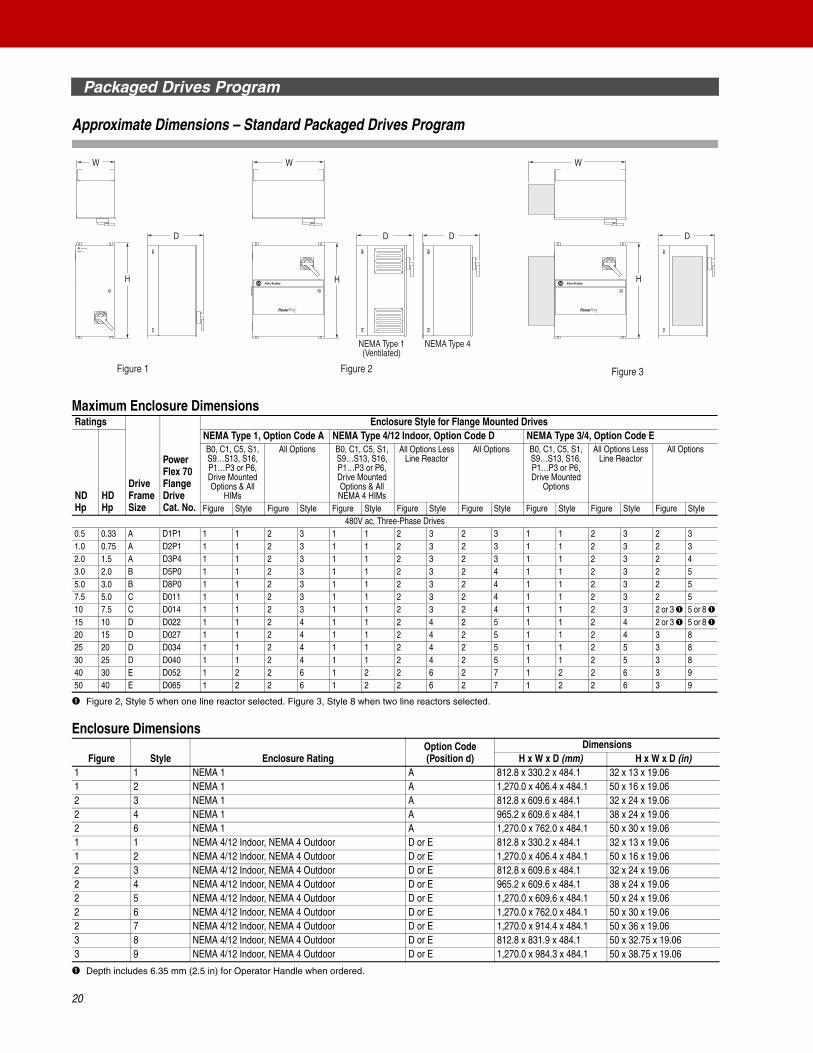
Approximate Dimensions – Standard Packaged Drives Program
Maximum Enclosure Dimensions
➊ Figure 2, Style 5 when one line reactor selected. Figure 3, Style 8 when two line reactors selected.
Enclosure Dimensions
➊ Depth includes 6.35 mm (2.5 in) for Operator Handle when ordered.
Ratings
Drive Frame Size
Power Flex 70 Flange Drive Cat. No.
Enclosure Style for Flange Mounted Drives
ND Hp
HD Hp
NEMA Type 1, Option Code A NEMA Type 4/12 Indoor, Option Code D NEMA Type 3/4, Option Code EB0, C1, C5, S1, S9…S13, S16, P1…P3 or P6, Drive Mounted Options & All
HIMs
All Options B0, C1, C5, S1, S9…S13, S16, P1…P3 or P6, Drive Mounted Options & All NEMA 4 HIMs
All Options Less Line Reactor
All Options B0, C1, C5, S1, S9…S13, S16, P1…P3 or P6, Drive Mounted
Options
All Options Less Line Reactor
All Options
Figure Style Figure Style Figure Style Figure Style Figure Style Figure Style Figure Style Figure Style480V ac, Three-Phase Drives
0.5 0.33 A D1P1 1 1 2 3 1 1 2 3 2 3 1 1 2 3 2 31.0 0.75 A D2P1 1 1 2 3 1 1 2 3 2 3 1 1 2 3 2 32.0 1.5 A D3P4 1 1 2 3 1 1 2 3 2 3 1 1 2 3 2 43.0 2.0 B D5P0 1 1 2 3 1 1 2 3 2 4 1 1 2 3 2 55.0 3.0 B D8P0 1 1 2 3 1 1 2 3 2 4 1 1 2 3 2 57.5 5.0 C D011 1 1 2 3 1 1 2 3 2 4 1 1 2 3 2 510 7.5 C D014 1 1 2 3 1 1 2 3 2 4 1 1 2 3 2 or 3 ➊ 5 or 8 ➊15 10 D D022 1 1 2 4 1 1 2 4 2 5 1 1 2 4 2 or 3 ➊ 5 or 8 ➊20 15 D D027 1 1 2 4 1 1 2 4 2 5 1 1 2 4 3 825 20 D D034 1 1 2 4 1 1 2 4 2 5 1 1 2 5 3 830 25 D D040 1 1 2 4 1 1 2 4 2 5 1 1 2 5 3 840 30 E D052 1 2 2 6 1 2 2 6 2 7 1 2 2 6 3 950 40 E D065 1 2 2 6 1 2 2 6 2 7 1 2 2 6 3 9
Figure Style Enclosure RatingOption Code (Position d)
DimensionsH x W x D (mm) H x W x D (in)
1 1 NEMA 1 A 812.8 x 330.2 x 484.1 32 x 13 x 19.061 2 NEMA 1 A 1,270.0 x 406.4 x 484.1 50 x 16 x 19.062 3 NEMA 1 A 812.8 x 609.6 x 484.1 32 x 24 x 19.062 4 NEMA 1 A 965.2 x 609.6 x 484.1 38 x 24 x 19.062 6 NEMA 1 A 1,270.0 x 762.0 x 484.1 50 x 30 x 19.061 1 NEMA 4/12 Indoor, NEMA 4 Outdoor D or E 812.8 x 330.2 x 484.1 32 x 13 x 19.061 2 NEMA 4/12 Indoor, NEMA 4 Outdoor D or E 1,270.0 x 406.4 x 484.1 50 x 16 x 19.062 3 NEMA 4/12 Indoor, NEMA 4 Outdoor D or E 812.8 x 609.6 x 484.1 32 x 24 x 19.062 4 NEMA 4/12 Indoor, NEMA 4 Outdoor D or E 965.2 x 609.6 x 484.1 38 x 24 x 19.062 5 NEMA 4/12 Indoor, NEMA 4 Outdoor D or E 1,270.0 x 609.6 x 484.1 50 x 24 x 19.062 6 NEMA 4/12 Indoor, NEMA 4 Outdoor D or E 1,270.0 x 762.0 x 484.1 50 x 30 x 19.062 7 NEMA 4/12 Indoor, NEMA 4 Outdoor D or E 1,270.0 x 914.4 x 484.1 50 x 36 x 19.063 8 NEMA 4/12 Indoor, NEMA 4 Outdoor D or E 812.8 x 831.9 x 484.1 50 x 32.75 x 19.063 9 NEMA 4/12 Indoor, NEMA 4 Outdoor D or E 1,270.0 x 984.3 x 484.1 50 x 38.75 x 19.06
H
W
H
D
W
H
DD
W
D
NEMA Type 1(Ventilated)
NEMA Type 4
Figure 1 Figure 2 Figure 3
Installation Considerations
21
Power Wiring
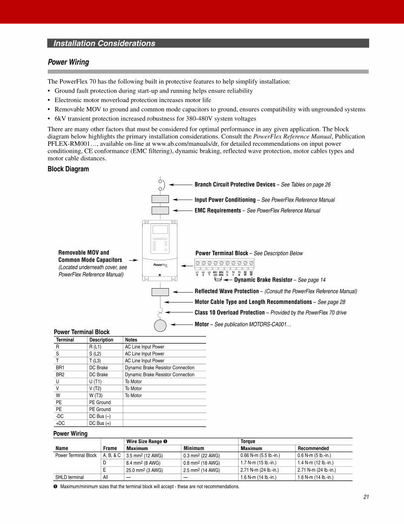
The PowerFlex 70 has the following built in protective features to help simplify installation:
• Ground fault protection during start-up and running helps ensure reliability
• Electronic motor moverload protection increases motor life
• Removable MOV to ground and common mode capacitors to ground, ensures compatibility with ungrounded systems
• 6kV transient protection increased robustness for 380-480V system voltages
There are many other factors that must be considered for optimal performance in any given application. The block diagram below highlights the primary installation considerations. Consult the PowerFlex Reference Manual, Publication PFLEX-RM001…, available on-line at www.ab.com/manuals/dr, for detailed recommendations on input power conditioning, CE conformance (EMC filtering), dynamic braking, reflected wave protection, motor cables types and motor cable distances.
Block Diagram
L1R
L2S
L3T
BR1+DC
BR2BRK
T1U
T2V
T3W
PE PE
Branch Circuit Protective Devices – See Tables on page 26
Class 10 Overload Protection – Provided by the PowerFlex 70 drive
EMC Requirements – See PowerFlex Reference Manual
Motor – See publication MOTORS-CA001…
Dynamic Brake Resistor – See page 14
Motor Cable Type and Length Recommendations – See page 28
Input Power Conditioning – See PowerFlex Reference Manual
Reflected Wave Protection – (Consult the PowerFlex Reference Manual)
Power Terminal Block – See Description BelowRemovable MOV andCommon Mode Capacitors(Located underneath cover, see PowerFlex Reference Manual)
Power Terminal Block Terminal Description NotesR R (L1) AC Line Input PowerS S (L2) AC Line Input PowerT T (L3) AC Line Input PowerBR1 DC Brake Dynamic Brake Resistor ConnectionBR2 DC Brake Dynamic Brake Resistor ConnectionU U (T1) To MotorV V (T2) To MotorW W (T3) To MotorPE PE GroundPE PE Ground-DC DC Bus (–)+DC DC Bus (+)
Power Wiring
➊ Maximum/minimum sizes that the terminal block will accept - these are not recommendations.
Name FrameWire Size Range ➊ TorqueMaximum Minimum Maximum Recommended
Power Terminal Block A, B, & C 3.5 mm2 (12 AWG) 0.3 mm2 (22 AWG) 0.66 N-m (5.5 lb.-in.) 0.6 N-m (5 lb.-in.)D 8.4 mm2 (8 AWG) 0.8 mm2 (18 AWG) 1.7 N-m (15 lb.-in.) 1.4 N-m (12 lb.-in.)E 25.0 mm2 (3 AWG) 2.5 mm2 (14 AWG) 2.71 N-m (24 lb.-in.) 2.71 N-m (24 lb.-in.)
SHLD terminal All — — 1.6 N-m (14 lb.-in.) 1.6 N-m (14 lb.-in.)
Installation Considerations
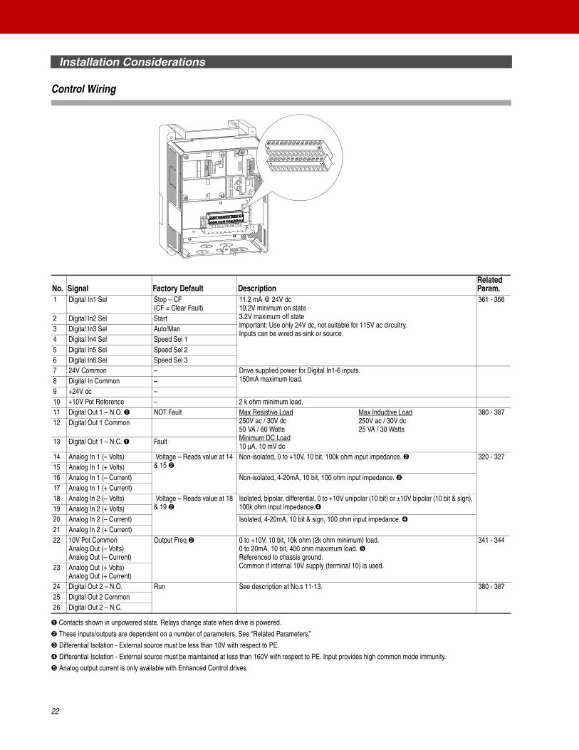
Control Wiring
➊ Contacts shown in unpowered state. Relays change state when drive is powered.
➋ These inputs/outputs are dependent on a number of parameters. See “Related Parameters.”
➌ Differential Isolation - External source must be less than 10V with respect to PE.
➍ Differential Isolation - External source must be maintained at less than 160V with respect to PE. Input provides high common mode immunity.
➎ Analog output current is only available with Enhanced Control drives.
No. Signal Factory Default DescriptionRelated Param.
1 Digital In1 Sel Stop – CF(CF = Clear Fault)
11.2 mA @ 24V dc19.2V minimum on state3.2V maximum off stateImportant: Use only 24V dc, not suitable for 115V ac circuitry.Inputs can be wired as sink or source.
361 - 366
2 Digital In2 Sel Start3 Digital In3 Sel Auto/Man4 Digital In4 Sel Speed Sel 15 Digital In5 Sel Speed Sel 26 Digital In6 Sel Speed Sel 37 24V Common – Drive supplied power for Digital In1-6 inputs.
150mA maximum load.8 Digital In Common –9 +24V dc –10 +10V Pot Reference – 2 k ohm minimum load.11 Digital Out 1 – N.O. ➊ NOT Fault Max Resistive Load
250V ac / 30V dc50 VA / 60 WattsMinimum DC Load10 µA, 10 mV dc
Max Inductive Load250V ac / 30V dc25 VA / 30 Watts
380 - 38712 Digital Out 1 Common
13 Digital Out 1 – N.C. ➊ Fault
14 Analog In 1 (– Volts) Voltage – Reads value at 14 & 15 ➋
Non-isolated, 0 to +10V, 10 bit, 100k ohm input impedance. ➌ 320 - 32715 Analog In 1 (+ Volts)16 Analog In 1 (– Current) Non-isolated, 4-20mA, 10 bit, 100 ohm input impedance. ➌17 Analog In 1 (+ Current)18 Analog In 2 (– Volts) Voltage – Reads value at 18
& 19 ➋Isolated, bipolar, differential, 0 to +10V unipolar (10 bit) or ±10V bipolar (10 bit & sign), 100k ohm input impedance.➍19 Analog In 2 (+ Volts)
20 Analog In 2 (– Current) Isolated, 4-20mA, 10 bit & sign, 100 ohm input impedance. ➍21 Analog In 2 (+ Current)22 10V Pot Common
Analog Out (– Volts)Analog Out (– Current)
Output Freq ➋ 0 to +10V, 10 bit, 10k ohm (2k ohm minimum) load.0 to 20mA, 10 bit, 400 ohm maximum load. ➎Referenced to chassis ground.Common if internal 10V supply (terminal 10) is used.
341 - 344
23 Analog Out (+ Volts)Analog Out (+ Current)
24 Digital Out 2 – N.O. Run See description at No.s 11-13. 380 - 38725 Digital Out 2 Common26 Digital Out 2 – N.C.
14 26
131
22

Installation Considerations
Control Wiring, Continued
I/O Wiring
➊ Maximum/minimum sizes that the terminal block will accept - these are not recommendations.
I/O Wiring Examples
NameWire Size Range ➊ TorqueMaximum Minimum Maximum Recommended
I/O Terminal Block 1.5 mm2 (16 AWG) 0.05 mm2 (30 AWG) 0.55 N-m (4.9 lb.-in.) 0.5 N-m (4.4 lb.-in.)
Input/Output Connection Example Required Parameter SettingsPotentiometer Unipolar Speed Reference10k Ohm Pot. Recommended(2k Ohm minimum)
Select Speed Reference source:Param. 090 = 1 “Analog In 1”Adjust Scaling:Param. 091, 092, 322, 323Check Results:Param. 016
Joystick Bipolar Speed Reference±10V Input
Set Direction Mode:Param. 190 = 1 “Bipolar”Adjust Scaling:Param. 091, 092, 325, 326Check Results:Param. 017
Analog Input Bipolar Speed Reference±10V Input
Adjust Scaling:Param. 091, 092, 325, 326Check Results:Param. 017
Analog Input Unipolar Speed Reference0 to +10V Input
Adjust Scaling:Param. 091, 092, 325, 326Check Results:Param. 017
Analog Input, PTCPTC OT set > 5VPTC OT cleared < 4VPTC Short < 0.2V
Set Fault Config 1:Param. 238, Bit #7 = 1 “Enabled”
Set Alarm Config 1:Param. 259, Bit #11 = 1 “Enabled”
Analog Input Unipolar Speed Reference4-20 mA Input
Configure Input for Current:Param. 320, Bit #1 = 1 “Current”Adjust Scaling:Param. 091, 092, 325, 326Check Results:Param. 017
Analog Output Unipolar0 to +10V Output. Can Drive a 2k Ohm load (25 mA short circuit limit)
Select Source Value:Param. 342Adjust Scaling:Param. 343, 344
1415
2210
18
19
22Com
Power Source-10V +10V
1819
–+
1819
Common
+
1415
2210
3.32kOhm
1.8kPTC
FerriteBead
2021
Common
+
+ –22
23
23

Installation Considerations
Control Wiring, Continued
2 Wire Control Non-Reversing Internal Supply Disable Digital Input 1:Param. 361 = 0 “Not Used”Set Digital Input 2:Param. 362 = 7 “Run”
2 Wire Control Reversing External Supply Set Digital Input 1:Param. 361 = 8 “Run Forward”Set Digital Input 2:Param. 362 = 9 “Run Reverse”
3 Wire Control Internal Supply Use factory default parameter settings.
3 Wire Control External Supply Use factory default parameter settings.
Digital OutputForm C Relays Energized in Normal State.
Select Source:Param. 380, 384
Enable InputShown in enabled state.
Standard ControlConfigure with parameter 366
Enhanced ControlConfigure with parameter 366For dedicated hardware Enable: Remove Enable Jumper
Input/Output Connection Example Required Parameter Settings
2
789
Stop-Run
+24V Common
12
8
Run Fwd
Run Rev
12
789
Stop
Start
+24V Common
12
8
Stop
Start
111213
242526Power
Source
or
6
24
Specifications
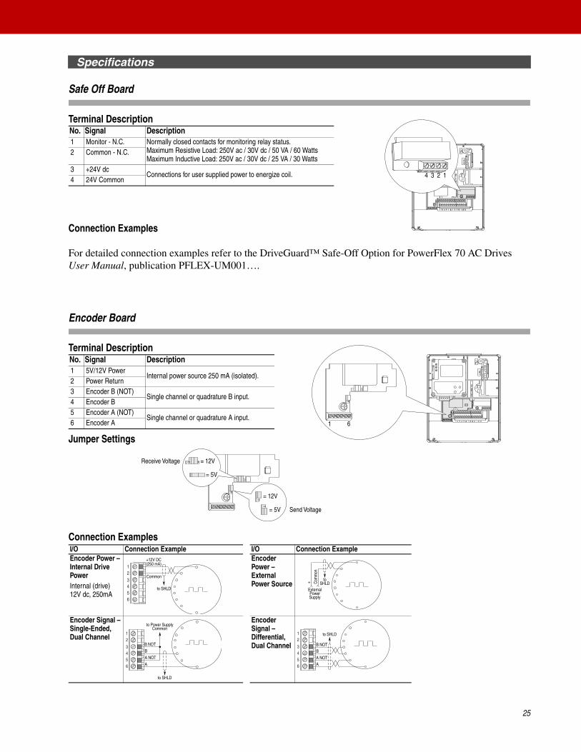
Safe Off Board
Terminal Description
Connection Examples
For detailed connection examples refer to the DriveGuard™ Safe-Off Option for PowerFlex 70 AC Drives User Manual, publication PFLEX-UM001….
Encoder Board
Terminal Description
Jumper Settings
Connection Examples
No. Signal Description1 Monitor - N.C. Normally closed contacts for monitoring relay status.
Maximum Resistive Load: 250V ac / 30V dc / 50 VA / 60 WattsMaximum Inductive Load: 250V ac / 30V dc / 25 VA / 30 Watts
2 Common - N.C.
3 +24V dcConnections for user supplied power to energize coil.
4 24V Common
No. Signal Description1 5V/12V Power
Internal power source 250 mA (isolated).2 Power Return3 Encoder B (NOT)
Single channel or quadrature B input.4 Encoder B5 Encoder A (NOT)
Single channel or quadrature A input.6 Encoder A
I/O Connection Example I/O Connection ExampleEncoder Power –Internal Drive PowerInternal (drive) 12V dc, 250mA
Encoder Power –External Power Source
Encoder Signal –Single-Ended, Dual Channel
Encoder Signal –Differential, Dual Channel
1234
61
= 12V
= 5V
= 12V
= 5V
Receive Voltage
Send Voltage
Common
+12V DC(250 mA)
6543
21
to SHLD
+ Com
mon
ExternalPowerSupply
toSHLD
A NOT
A
B
B NOT
to SHLD
to Power SupplyCommon
6543
21 to SHLD
6543
21
A NOT
B
A
B NOT
25
Specifications
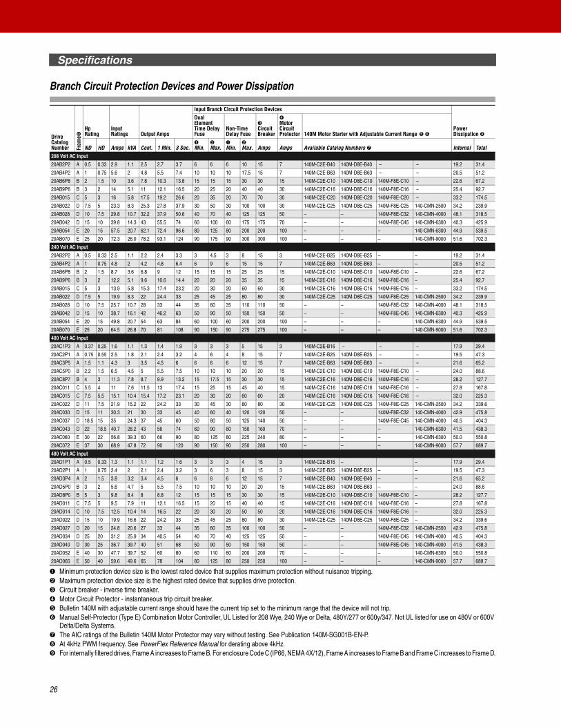
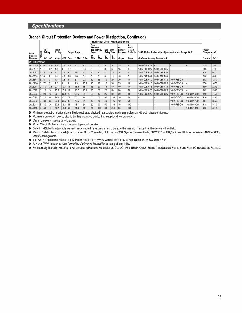
Branch Circuit Protection Devices and Power Dissipation
➊ Minimum protection device size is the lowest rated device that supplies maximum protection without nuisance tripping.➋ Maximum protection device size is the highest rated device that supplies drive protection.➌ Circuit breaker - inverse time breaker.➍ Motor Circuit Protector - instantaneous trip circuit breaker.➎ Bulletin 140M with adjustable current range should have the current trip set to the minimum range that the device will not trip.➏ Manual Self-Protector (Type E) Combination Motor Controller, UL Listed for 208 Wye, 240 Wye or Delta, 480Y/277 or 600y/347. Not UL listed for use on 480V or 600V
Delta/Delta Systems.➐ The AIC ratings of the Bulletin 140M Motor Protector may vary without testing. See Publication 140M-SG001B-EN-P.➑ At 4kHz PWM frequency. See PowerFlex Reference Manual for derating above 4kHz.➒ For internally filtered drives, Frame A increases to Frame B. For enclosure Code C (IP66, NEMA 4X/12), Frame A increases to Frame B and Frame C increases to Frame D.
DriveCatalogNumber Fr
ame➒
HpRating
Input Ratings Output Amps
Input Branch Circuit Protection Devices
Power Dissipation ➑
DualElement Time Delay Fuse
Non-Time Delay Fuse
➌Circuit Breaker
➍Motor Circuit Protector 140M Motor Starter with Adjustable Current Range ➎ ➏
ND HD Amps kVA Cont. 1 Min. 3 Sec.➊Min.
➋Max.
➊Min.
➋Max. Amps Amps Available Catalog Numbers ➐ Internal Total
208 Volt AC Input
20AB2P2 A 0.5 0.33 2.9 1.1 2.5 2.7 3.7 6 6 6 10 15 7 140M-C2E-B40 140M-D8E-B40 – – 19.2 31.4
20AB4P2 A 1 0.75 5.6 2 4.8 5.5 7.4 10 10 10 17.5 15 7 140M-C2E-B63 140M-D8E-B63 – – 20.5 51.2
20AB6P8 B 2 1.5 10 3.6 7.8 10.3 13.8 15 15 15 30 30 15 140M-C2E-C10 140M-D8E-C10 140M-F8E-C10 – 22.6 67.2
20AB9P6 B 3 2 14 5.1 11 12.1 16.5 20 25 20 40 40 30 140M-C2E-C16 140M-D8E-C16 140M-F8E-C16 – 25.4 92.7
20AB015 C 5 3 16 5.8 17.5 19.2 26.6 20 35 20 70 70 30 140M-C2E-C20 140M-D8E-C20 140M-F8E-C20 – 33.2 174.5
20AB022 D 7.5 5 23.3 8.3 25.3 27.8 37.9 30 50 30 100 100 30 140M-C2E-C25 140M-D8E-C25 140M-F8E-C25 140-CMN-2500 34.2 239.9
20AB028 D 10 7.5 29.8 10.7 32.2 37.9 50.6 40 70 40 125 125 50 – – 140M-F8E-C32 140-CMN-4000 48.1 318.5
20AB042 D 15 10 39.8 14.3 43 55.5 74 60 100 60 175 175 70 – – 140M-F8E-C45 140-CMN-6300 40.3 425.9
20AB054 E 20 15 57.5 20.7 62.1 72.4 96.6 80 125 80 200 200 100 – – – 140-CMN-6300 44.9 539.5
20AB070 E 25 20 72.3 26.0 78.2 93.1 124 90 175 90 300 300 100 – – – 140-CMN-9000 51.6 702.3
240 Volt AC Input
20AB2P2 A 0.5 0.33 2.5 1.1 2.2 2.4 3.3 3 4.5 3 8 15 3 140M-C2E-B25 140M-D8E-B25 – – 19.2 31.4
20AB4P2 A 1 0.75 4.8 2 4.2 4.8 6.4 6 9 6 15 15 7 140M-C2E-B63 140M-D8E-B63 – – 20.5 51.2
20AB6P8 B 2 1.5 8.7 3.6 6.8 9 12 15 15 15 25 25 15 140M-C2E-C10 140M-D8E-C10 140M-F8E-C10 – 22.6 67.2
20AB9P6 B 3 2 12.2 5.1 9.6 10.6 14.4 20 20 20 35 35 15 140M-C2E-C16 140M-D8E-C16 140M-F8E-C16 – 25.4 92.7
20AB015 C 5 3 13.9 5.8 15.3 17.4 23.2 20 30 20 60 60 30 140M-C2E-C16 140M-D8E-C16 140M-F8E-C16 – 33.2 174.5
20AB022 D 7.5 5 19.9 8.3 22 24.4 33 25 45 25 80 80 30 140M-C2E-C25 140M-D8E-C25 140M-F8E-C25 140-CMN-2500 34.2 239.9
20AB028 D 10 7.5 25.7 10.7 28 33 44 35 60 35 110 110 50 – – 140M-F8E-C32 140-CMN-4000 48.1 318.5
20AB042 D 15 10 38.7 16.1 42 46.2 63 50 90 50 150 150 50 – – 140M-F8E-C45 140-CMN-6300 40.3 425.9
20AB054 E 20 15 49.8 20.7 54 63 84 60 100 60 200 200 100 – – – 140-CMN-6300 44.9 539.5
20AB070 E 25 20 64.5 26.8 70 81 108 90 150 90 275 275 100 – – – 140-CMN-9000 51.6 702.3
400 Volt AC Input
20AC1P3 A 0.37 0.25 1.6 1.1 1.3 1.4 1.9 3 3 3 5 15 3 140M-C2E-B16 – – – 17.9 29.4
20AC2P1 A 0.75 0.55 2.5 1.8 2.1 2.4 3.2 4 6 4 8 15 7 140M-C2E-B25 140M-D8E-B25 – – 19.5 47.3
20AC3P5 A 1.5 1.1 4.3 3 3.5 4.5 6 6 6 6 12 15 7 140M-C2E-B63 140M-D8E-B63 – – 21.6 65.2
20AC5P0 B 2.2 1.5 6.5 4.5 5 5.5 7.5 10 10 10 20 20 15 140M-C2E-C10 140M-D8E-C10 140M-F8E-C10 – 24.0 88.6
20AC8P7 B 4 3 11.3 7.8 8.7 9.9 13.2 15 17.5 15 30 30 15 140M-C2E-C16 140M-D8E-C16 140M-F8E-C16 – 28.2 127.7
20AC011 C 5.5 4 11 7.6 11.5 13 17.4 15 25 15 45 40 15 140M-C2E-C16 140M-D8E-C16 140M-F8E-C16 – 27.8 167.8
20AC015 C 7.5 5.5 15.1 10.4 15.4 17.2 23.1 20 30 20 60 60 20 140M-C2E-C16 140M-D8E-C16 140M-F8E-C16 – 32.0 225.3
20AC022 D 11 7.5 21.9 15.2 22 24.2 33 30 45 30 80 80 30 140M-C2E-C25 140M-D8E-C25 140M-F8E-C25 140-CMN-2500 34.2 339.6
20AC030 D 15 11 30.3 21 30 33 45 40 60 40 120 120 50 – – 140M-F8E-C32 140-CMN-4000 42.9 475.8
20AC037 D 18.5 15 35 24.3 37 45 60 50 80 50 125 140 50 – – 140M-F8E-C45 140-CMN-4000 40.5 404.3
20AC043 D 22 18.5 40.7 28.2 43 56 74 60 90 60 150 160 70 – – – 140-CMN-6300 41.5 438.3
20AC060 E 30 22 56.8 39.3 60 66 90 80 125 80 225 240 80 – – – 140-CMN-6300 50.0 550.8
20AC072 E 37 30 68.9 47.8 72 90 120 90 150 90 250 280 100 – – – 140-CMN-9000 57.7 689.7
480 Volt AC Input
20AD1P1 A 0.5 0.33 1.3 1.1 1.1 1.2 1.6 3 3 3 4 15 3 140M-C2E-B16 – – 17.9 29.4
20AD2P1 A 1 0.75 2.4 2 2.1 2.4 3.2 3 6 3 8 15 3 140M-C2E-B25 140M-D8E-B25 – – 19.5 47.3
20AD3P4 A 2 1.5 3.8 3.2 3.4 4.5 6 6 6 6 12 15 7 140M-C2E-B40 140M-D8E-B40 – – 21.6 65.2
20AD5P0 B 3 2 5.6 4.7 5 5.5 7.5 10 10 10 20 20 15 140M-C2E-B63 140M-D8E-B63 – – 24.0 88.6
20AD8P0 B 5 3 9.8 8.4 8 8.8 12 15 15 15 30 30 15 140M-C2E-C10 140M-D8E-C10 140M-F8E-C10 – 28.2 127.7
20AD011 C 7.5 5 9.5 7.9 11 12.1 16.5 15 20 15 40 40 15 140M-C2E-C16 140M-D8E-C16 140M-F8E-C16 – 27.8 167.8
20AD014 C 10 7.5 12.5 10.4 14 16.5 22 20 30 20 50 50 20 140M-C2E-C16 140M-D8E-C16 140M-F8E-C16 – 32.0 225.3
20AD022 D 15 10 19.9 16.6 22 24.2 33 25 45 25 80 80 30 140M-C2E-C25 140M-D8E-C25 140M-F8E-C25 – 34.2 339.6
20AD027 D 20 15 24.8 20.6 27 33 44 35 60 35 100 100 50 – – 140M-F8E-C32 140-CMN-2500 42.9 475.8
20AD034 D 25 20 31.2 25.9 34 40.5 54 40 70 40 125 125 50 – – 140M-F8E-C45 140-CMN-4000 40.5 404.3
20AD040 D 30 25 36.7 39.7 40 51 68 50 90 50 150 150 50 – – 140M-F8E-C45 140-CMN-4000 41.5 438.3
20AD052 E 40 30 47.7 39.7 52 60 80 60 110 60 200 200 70 – – – 140-CMN-6300 50.0 550.8
20AD065 E 50 40 59.6 49.6 65 78 104 80 125 80 250 250 100 – – – 140-CMN-9000 57.7 689.7
26
Specifications
Branch Circuit Protection Devices and Power Dissipation, Continued)
➊ Minimum protection device size is the lowest rated device that supplies maximum protection without nuisance tripping.➋ Maximum protection device size is the highest rated device that supplies drive protection.➌ Circuit breaker - inverse time breaker.➍ Motor Circuit Protector - instantaneous trip circuit breaker.➎ Bulletin 140M with adjustable current range should have the current trip set to the minimum range that the device will not trip.➏ Manual Self-Protector (Type E) Combination Motor Controller, UL Listed for 208 Wye, 240 Wye or Delta, 480Y/277 or 600y/347. Not UL listed for use on 480V or 600V
Delta/Delta Systems.➐ The AIC ratings of the Bulletin 140M Motor Protector may vary without testing. See Publication 140M-SG001B-EN-P.➑ At 4kHz PWM frequency. See PowerFlex Reference Manual for derating above 4kHz.➒ For internally filtered drives, Frame A increases to Frame B. For enclosure Code C (IP66, NEMA 4X/12), Frame A increases to Frame B and Frame C increases to Frame D.
DriveCatalogNumber Fr
ame➒
HpRating
Input Ratings Output Amps
Input Branch Circuit Protection Devices
Power Dissipation ➑
DualElement Time Delay Fuse
Non-Time Delay Fuse
➌Circuit Breaker
➍Motor Circuit Protector 140M Motor Starter with Adjustable Current Range ➎ ➏
ND HD Amps kVA Cont. 1 Min. 3 Sec.➊Min.
➋Max.
➊Min.
➋Max. Amps Amps Available Catalog Numbers ➐ Internal Total
600 Volt AC Input
20AE0P9 A 0.5 0.33 1.3 1.3 0.9 1.1 1.4 3 3 3 3.5 15 3 140M-C2E-B16 – – – 17.9 29.4
20AE1P7 A 1 0.75 1.9 2 1.7 2 2.6 3 6 3 6 15 3 140M-C2E-B25 140M-D8E-B25 – – 19.5 47.3
20AE2P7 A 2 1.5 3 3.1 2.7 3.6 4.8 4 6 4 10 15 7 140M-C2E-B40 140M-D8E-B40 – – 21.6 65.2
20AE3P9 B 3 2 4.4 4.5 3.9 4.3 5.9 6 8 6 15 15 7 140M-C2E-B63 140M-D8E-B63 – – 24.0 88.6
20AE6P1 B 5 3 7.5 7.8 6.1 6.7 9.2 10 12 10 20 20 15 140M-C2E-C10 140M-D8E-C10 140M-F8E-C10 – 28.2 127.7
20AE9P0 C 7.5 5 7.7 8 9 9.9 13.5 10 20 10 35 35 15 140M-C2E-C10 140M-D8E-C10 140M-F8E-C10 – 27.8 167.8
20AE011 C 10 7.5 9.8 10.1 11 13.5 18 15 20 15 40 40 15 140M-C2E-C16 140M-D8E-C16 140M-F8E-C16 – 32.0 225.3
20AE017 D 15 10 15.3 15.9 17 18.7 25.5 20 35 20 60 60 30 140M-C2E-C20 140M-D8E-C20 140M-F8E-C20 – 34.2 339.6
20AE022 D 20 15 20 20.8 22 25.5 34 25 45 25 80 80 30 140M-C2E-C25 140M-D8E-C25 140M-F8E-C25 140-CMN-2500 42.9 475.8
20AE027 D 25 20 24.8 25.7 27 33 44 35 60 35 100 100 50 – – 140M-F8E-C25 140-CMN-2500 42.4 323.8
20AE032 D 30 25 29.4 30.5 32 40.5 54 40 70 40 125 125 50 – – 140M-F8E-C32 140-CMN-4000 43.4 355.3
20AE041 E 40 30 37.6 39.1 41 48 64 50 90 50 150 150 100 – – 140M-F8E-C45 140-CMN-4000 51.8 441.7
20AE052 E 50 40 47.7 49.6 52 61.5 82 60 110 60 200 200 100 – – – 140-CMN-6300 59.9 561.3
27
Specifications
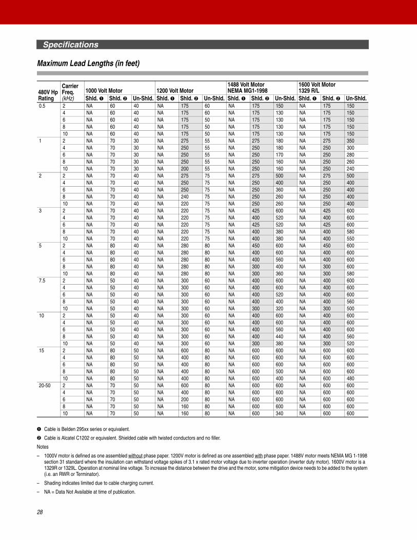
Maximum Lead Lengths (in feet)
➊ Cable is Belden 295xx series or equivalent.
➋ Cable is Alcatel C1202 or equivalent. Shielded cable with twisted conductors and no filler.
Notes
– 1000V motor is defined as one assembled without phase paper. 1200V motor is defined as one assembled with phase paper. 1488V motor meets NEMA MG 1-1998 section 31 standard where the insulation can withstand voltage spikes of 3.1 x rated motor voltage due to inverter operation (inverter duty motor). 1600V motor is a 1329R or 1329L. Operation at nominal line voltage. To increase the distance between the drive and the motor, some mitigation device needs to be added to the system (i.e. an RWR or Terminator).
– Shading indicates limited due to cable charging current.
– NA = Data Not Available at time of publication.
480V Hp Rating
Carrier Freq. (kHz)
1000 Volt Motor 1200 Volt Motor1488 Volt MotorNEMA MG1-1998
1600 Volt Motor1329 R/L
Shld. ➊ Shld. ➋ Un-Shld. Shld. ➊ Shld. ➋ Un-Shld. Shld. ➊ Shld. ➋ Un-Shld. Shld. ➊ Shld. ➋ Un-Shld.0.5 2 NA 60 40 NA 175 60 NA 175 150 NA 175 150
4 NA 60 40 NA 175 60 NA 175 130 NA 175 1506 NA 60 40 NA 175 50 NA 175 130 NA 175 1508 NA 60 40 NA 175 50 NA 175 130 NA 175 15010 NA 60 40 NA 175 50 NA 175 130 NA 175 150
1 2 NA 70 30 NA 275 55 NA 275 180 NA 275 3504 NA 70 30 NA 250 55 NA 250 180 NA 250 3006 NA 70 30 NA 250 55 NA 250 170 NA 250 2808 NA 70 30 NA 250 55 NA 250 160 NA 250 26010 NA 70 30 NA 200 55 NA 250 160 NA 250 240
2 2 NA 70 40 NA 275 75 NA 275 500 NA 275 5004 NA 70 40 NA 250 75 NA 250 400 NA 250 4006 NA 70 40 NA 250 75 NA 250 360 NA 250 4008 NA 70 40 NA 240 75 NA 250 260 NA 250 40010 NA 70 40 NA 220 75 NA 250 260 NA 250 400
3 2 NA 70 40 NA 220 75 NA 425 600 NA 425 6004 NA 70 40 NA 220 75 NA 400 520 NA 400 6006 NA 70 40 NA 220 75 NA 425 520 NA 425 6008 NA 70 40 NA 220 75 NA 400 380 NA 400 58010 NA 70 40 NA 220 75 NA 400 380 NA 400 550
5 2 NA 80 40 NA 280 80 NA 450 600 NA 450 6004 NA 80 40 NA 280 80 NA 400 600 NA 400 6006 NA 80 40 NA 280 80 NA 400 560 NA 400 6008 NA 80 40 NA 280 80 NA 300 400 NA 300 60010 NA 80 40 NA 280 80 NA 300 360 NA 300 580
7.5 2 NA 50 40 NA 300 60 NA 400 600 NA 400 6004 NA 50 40 NA 300 60 NA 400 600 NA 400 6006 NA 50 40 NA 300 60 NA 400 520 NA 400 6008 NA 50 40 NA 300 60 NA 400 400 NA 400 56010 NA 50 40 NA 300 60 NA 300 320 NA 300 500
10 2 NA 50 40 NA 300 60 NA 400 600 NA 400 6004 NA 50 40 NA 300 60 NA 400 600 NA 400 6006 NA 50 40 NA 300 60 NA 400 560 NA 400 6008 NA 50 40 NA 300 60 NA 400 440 NA 400 56010 NA 50 40 NA 300 60 NA 300 380 NA 300 520
15 2 NA 80 50 NA 600 80 NA 600 600 NA 600 6004 NA 80 50 NA 400 80 NA 600 600 NA 600 6006 NA 80 50 NA 400 80 NA 600 600 NA 600 6008 NA 80 50 NA 400 80 NA 600 500 NA 600 60010 NA 80 50 NA 400 80 NA 600 400 NA 600 480
20-50 2 NA 70 50 NA 600 80 NA 600 600 NA 600 6004 NA 70 50 NA 400 80 NA 600 600 NA 600 6006 NA 70 50 NA 200 80 NA 600 600 NA 600 6008 NA 70 50 NA 160 80 NA 600 600 NA 600 60010 NA 70 50 NA 160 80 NA 600 340 NA 600 600
28

Specifications
Control and Performance
➊ Applied noise impulses may be counted in addition to the standard pulse train causing erroneously high (pulse frequency) readings.
Category SpecificationProtection PowerFlex 70 Drive 200-208V Drive 240V Drive 380/400 Drive 480V Drive 600V Drive
AC Input Overvoltage Trip: 247VAC 285VAC 475VAC 570VAC 690VACAC Input Undervoltage Trip: 120VAC 138VAC 233VAC 280VAC 345VACBus Overvoltage Trip: 350VDC 405VDC 675VDC 810VDC 1013VDCBus Undervoltage Trip: 176VDC 204VDC 339VDC 407VDC 998VDCNominal Bus Voltage: 281VDC 324VDC 540VDC 648VDC 810VDCAll DrivesHeat Sink Thermistor: Monitored by microprocessor overtemp tripDrive Overcurrent Trip
Software Current Limit:Hardware Current Limit:Instantaneous Current Limit:
20-160% of rated current200% of rated current (typical)220-300% of rated current (dependent on drive rating)
Line transients: up to 6000 volts peak per IEEE C62.41-1991Control Logic Noise Immunity: Showering arc transients up to 1500V peakPower Ride-Thru: 15 milliseconds at full loadLogic Control Ride-Thru: 0.5 seconds minimum, 2 seconds typicalGround Fault Trip: Phase-to-ground on drive outputShort Circuit Trip: Phase-to-phase on drive output
Environment Altitude: 1000 m (3300 ft) max. without deratingMaximum Surrounding Air Temperature without derating:
IP20, NEMA Type 1IP66, NEMA Type 4X/12Flange Type
0 to 50 degrees C (32 to 122 degrees F)0 to 40 degrees C (32 to 104 degrees F)0 to 50 degrees C (32 to 122 degrees F)
Storage Temperature (all const.): –40 to 70 degrees C (–40 to 158 degrees F)Atmosphere Important: Drive must not be installed in an area where the ambient atmosphere contains volatile
or corrosive gas, vapors or dust. If the drive is not going to be installed for a period of time, it must be stored in an area where it will not be exposed to a corrosive atmosphere.
Relative Humidity: 5 to 95% non-condensingShock: 15G peak for 11ms duration (±1.0 ms)Vibration: 0.152 mm (0.006 in.) displacement, 1G peak
Agency Certification
Type 1, IP30 Flange Type Type 4X/12, IP66
✔ ✔ ✔ Listed to UL508C and CAN/CSA-C2.2 No. 14-M91
✔ Listed to UL508C for plenums (Rear heatsink only)
✔ ✔ ✔ Marked for all applicable European Directives ➊EMC Directive (89/336/EEC)EN 61800-3 Adjustable Speed electrical power drive systemsLow Voltage Directive (73/23/EEC)EN 50178 Electronic Equipment for use in Power Installations
✔ ✔ ✔ Certified to AS/NZS, 1997 Group 1, Class A
✔ ✔ ✔ Certified to Criteria C-2, 1983.
✔ ✔ ✔ Certified to EN 954-1, Category 3 for 240V, 400V, and 480V ratings of PowerFlex 70 Enhanced Control with DriveGuard Safe-Off option.
✔ ✔ ✔ TUV Approved to EN 954-1, Category 3 for 600V ratings of PowerFlex 70 Enhanced Control with DriveGuard Safe-Off option.
The drive is also designed to meet the appropriate portions of the following specifications:NFPA 70 - US National Electrical CodeNEMA ICS 3.1 - Safety standards for Construction and Guide for Selection, Installation and Operation of Adjustable Speed Drive Systems.IEC 146 - International Electrical Code.
UL®C US
TUV Rheinland
Product Safety
..
Production inspected
W
E C
TUV Rheinland
..Functional
Safety
Bauart geprüft
Type approved
EN 50178
29

Specifications
Control and Performance, Continued
Category SpecificationElectrical Voltage Tolerance: –10% of minimum, +10% of maximum. See the PowerFlex User Manual,
publication 20A-UM001…, for Full Power and Operating Range.Frequency Tolerance: 47-63 Hz.Input Phases: Three-phase input provides full rating for all drives. Single-phase operation provides 50% of rated current.Displacement Power FactorAll Drives: 0.98 across entire speed range.Efficiency: 97.5% at rated amps, nominal line volts.Maximum Short Circuit Rating: 200,000 Amps symmetrical.Actual Short Circuit Rating: Determined by AIC rating of installed fuse/circuit breaker.
Control Method: Sine coded PWM with programmable carrier frequency. Ratings apply to all drives.Carrier Frequency: 2, 3, 4, 5, 6, 7, 8, 9 & 10 kHz .
2, 4, 8 & 12 kHz . Drive rating based on 4 kHz
Output Voltage Range: 0 to rated motor voltageOutput Frequency Range: 0 to 400 Hz . 0 to 500 Hz .Frequency AccuracyDigital Input:Analog Input:
Within ±0.01% of set output frequency.Within ±0.4% of maximum output frequency.
Frequency Control Speed regulation - with Slip Compensation0.5% of base speed across 40:1 speed range40:1 operating range10 rad/sec bandwidth
(Volts per Hertz Mode)
Speed regulation - with Slip Compensation0.5% of base speed across 80:1 speed range80:1 operating range20 rad/sec bandwidth
(Sensorless Vector Mode)
Speed regulation - with feedback0.1% of base speed across 80:1 speed range80:1 operating range20 rad/sec bandwidth
(Sensorless Vector Mode)
Speed Control Speed regulation - without feedback0.1% of base speed across 120:1 speed range120:1 operating range30 rad/sec bandwidth
(Vector Control Mode)
Speed regulation - with feedback0.001% of base speed across 120:1 speed range1000:1 operating range125 rad/sec bandwidth
(Vector Control Mode)
Torque Regulation Torque regulation - without feedback +/-10%
Torque regulation - with feedback +/-5%
Selectable Motor Control: Sensorless Vector with full tuning. Standard V/Hz with full custom capability and vector control.Stop Modes: Multiple programmable stop modes including - Ramp, Coast, DC-Brake, Ramp-to-Hold and S-curve.Accel/Decel: Two independently programmable accel and decel times. Each time may be programmed from 0-3600
seconds in 0.1 sec. incrementsIntermittent Overload: 110% Overload capability for up to 1 minute
150% Overload capability for up to 3 seconds Current Limit Capability: Proactive Current Limit programmable from 20 to 160% of rated output current. Independently
programmable proportional and integral gain.Electronic Motor Overload Protection: Class 10 protection with speed sensitive response. Investigated by U.L. to comply with N.E.C. Article
430. U.L. File E59272, volume 12.Encoder Type: Incremental, dual channel
Supply: 5V/12V Configurable +/-5%Quadrature: 90° +/-27° at 25° C.Duty Cycle: 50% +10%Requirements Encoders must be line driver type, quadrature (dual channel) or pulse (single channel), single-ended or
differential and capable of supplying a minimum of 10 mA per channel. The Encoder Interface Board accepts 5V or 12V dc square-wave with a minimum high state voltage of 3.5V dc (5V mode) and 7.0V dc (12V mode). Maximum low state voltage is 1V dc (for both 5V and 12V modes). Maximum input frequency is 250 kHz.
Standard
E C
Standard E C
Standard E C
Standard E C
E C
E C
E C
E C
E C
30
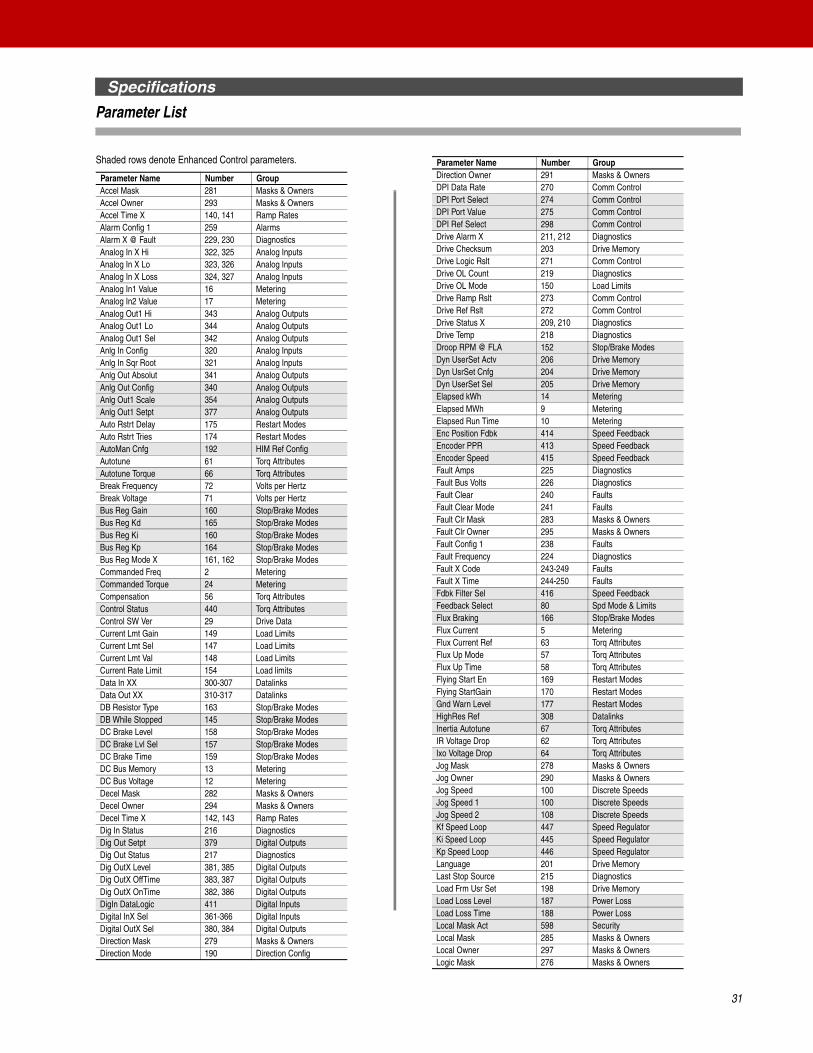
Specifications
Parameter List
Shaded rows denote Enhanced Control parameters.
Parameter Name Number GroupAccel Mask 281 Masks & OwnersAccel Owner 293 Masks & OwnersAccel Time X 140, 141 Ramp RatesAlarm Config 1 259 AlarmsAlarm X @ Fault 229, 230 DiagnosticsAnalog In X Hi 322, 325 Analog InputsAnalog In X Lo 323, 326 Analog InputsAnalog In X Loss 324, 327 Analog InputsAnalog In1 Value 16 MeteringAnalog In2 Value 17 MeteringAnalog Out1 Hi 343 Analog OutputsAnalog Out1 Lo 344 Analog OutputsAnalog Out1 Sel 342 Analog OutputsAnlg In Config 320 Analog InputsAnlg In Sqr Root 321 Analog InputsAnlg Out Absolut 341 Analog OutputsAnlg Out Config 340 Analog OutputsAnlg Out1 Scale 354 Analog OutputsAnlg Out1 Setpt 377 Analog OutputsAuto Rstrt Delay 175 Restart ModesAuto Rstrt Tries 174 Restart ModesAutoMan Cnfg 192 HIM Ref ConfigAutotune 61 Torq AttributesAutotune Torque 66 Torq AttributesBreak Frequency 72 Volts per HertzBreak Voltage 71 Volts per HertzBus Reg Gain 160 Stop/Brake ModesBus Reg Kd 165 Stop/Brake ModesBus Reg Ki 160 Stop/Brake ModesBus Reg Kp 164 Stop/Brake ModesBus Reg Mode X 161, 162 Stop/Brake ModesCommanded Freq 2 MeteringCommanded Torque 24 MeteringCompensation 56 Torq AttributesControl Status 440 Torq AttributesControl SW Ver 29 Drive DataCurrent Lmt Gain 149 Load LimitsCurrent Lmt Sel 147 Load LimitsCurrent Lmt Val 148 Load LimitsCurrent Rate Limit 154 Load limitsData In XX 300-307 DatalinksData Out XX 310-317 DatalinksDB Resistor Type 163 Stop/Brake ModesDB While Stopped 145 Stop/Brake ModesDC Brake Level 158 Stop/Brake ModesDC Brake Lvl Sel 157 Stop/Brake ModesDC Brake Time 159 Stop/Brake ModesDC Bus Memory 13 MeteringDC Bus Voltage 12 MeteringDecel Mask 282 Masks & OwnersDecel Owner 294 Masks & OwnersDecel Time X 142, 143 Ramp RatesDig In Status 216 DiagnosticsDig Out Setpt 379 Digital OutputsDig Out Status 217 DiagnosticsDig OutX Level 381, 385 Digital OutputsDig OutX OffTime 383, 387 Digital OutputsDig OutX OnTime 382, 386 Digital OutputsDigIn DataLogic 411 Digital InputsDigital InX Sel 361-366 Digital InputsDigital OutX Sel 380, 384 Digital OutputsDirection Mask 279 Masks & OwnersDirection Mode 190 Direction Config
Direction Owner 291 Masks & OwnersDPI Data Rate 270 Comm ControlDPI Port Select 274 Comm ControlDPI Port Value 275 Comm ControlDPI Ref Select 298 Comm ControlDrive Alarm X 211, 212 DiagnosticsDrive Checksum 203 Drive MemoryDrive Logic Rslt 271 Comm ControlDrive OL Count 219 DiagnosticsDrive OL Mode 150 Load LimitsDrive Ramp Rslt 273 Comm ControlDrive Ref Rslt 272 Comm ControlDrive Status X 209, 210 DiagnosticsDrive Temp 218 DiagnosticsDroop RPM @ FLA 152 Stop/Brake ModesDyn UserSet Actv 206 Drive MemoryDyn UsrSet Cnfg 204 Drive MemoryDyn UserSet Sel 205 Drive MemoryElapsed kWh 14 MeteringElapsed MWh 9 MeteringElapsed Run Time 10 MeteringEnc Position Fdbk 414 Speed FeedbackEncoder PPR 413 Speed FeedbackEncoder Speed 415 Speed FeedbackFault Amps 225 DiagnosticsFault Bus Volts 226 DiagnosticsFault Clear 240 FaultsFault Clear Mode 241 FaultsFault Clr Mask 283 Masks & OwnersFault Clr Owner 295 Masks & OwnersFault Config 1 238 FaultsFault Frequency 224 DiagnosticsFault X Code 243-249 FaultsFault X Time 244-250 FaultsFdbk Filter Sel 416 Speed FeedbackFeedback Select 80 Spd Mode & LimitsFlux Braking 166 Stop/Brake ModesFlux Current 5 MeteringFlux Current Ref 63 Torq AttributesFlux Up Mode 57 Torq AttributesFlux Up Time 58 Torq AttributesFlying Start En 169 Restart ModesFlying StartGain 170 Restart ModesGnd Warn Level 177 Restart ModesHighRes Ref 308 DatalinksInertia Autotune 67 Torq AttributesIR Voltage Drop 62 Torq AttributesIxo Voltage Drop 64 Torq AttributesJog Mask 278 Masks & OwnersJog Owner 290 Masks & OwnersJog Speed 100 Discrete SpeedsJog Speed 1 100 Discrete SpeedsJog Speed 2 108 Discrete SpeedsKf Speed Loop 447 Speed RegulatorKi Speed Loop 445 Speed RegulatorKp Speed Loop 446 Speed RegulatorLanguage 201 Drive MemoryLast Stop Source 215 DiagnosticsLoad Frm Usr Set 198 Drive MemoryLoad Loss Level 187 Power LossLoad Loss Time 188 Power LossLocal Mask Act 598 SecurityLocal Mask 285 Masks & OwnersLocal Owner 297 Masks & OwnersLogic Mask 276 Masks & Owners
Parameter Name Number Group
31

Specifications
Parameter List, Continued
Man Ref Preload 193 HIM Ref ConfigMaximum Freq 55 Torq AttributesMaximum Speed 82 Spd Mode & LimitsMaximum Voltage 54 Torq AttributesMinimum Speed 81 Spd Mode & LimitsMOP Frequency 11 MeteringMOP Mask 284 Masks & OwnersMOP Owner 296 Masks & OwnersMOP Rate 195 MOP ConfigMotor Cntl Sel 53 Torq AttributesMotor Fdbk Type 412 Speed FeedbackMotor NP FLA 42 Motor DataMotor NP Hertz 43 Motor DataMotor NP Power 45 Motor DataMotor NP RPM 44 Motor DataMotor NP Volts 41 Motor DataMotor OL Count 220 DiagnosticsMotor OL Factor 48 Motor DataMotor OL Hertz 47 Motor DataMotor Poles 49 Motor DataMotor Type 40 Motor DataMtr NP Pwr Units 46 Motor DataNeg Torque Limit 437 Torq AttributesNotch Filter K 420 Speed FeedbackNotch FilterFreq 419 Speed FeedbackOutput Current 3 MeteringOutput Freq 1 MeteringOutput Power 7 MeteringOutput Powr Fctr 8 MeteringOutput Voltage 6 MeteringOverspeed Limit 83 Spd Mode & LimitsParam Access Lvl 196 Drive MemoryPI BW Filter 139 Process PIPI Configuration 124 Process PIPI Control 125 Process PIPI Deriv Time 459 Process PIPI Error Meter 137 Process PIPI Fdback Meter 136 Process PIPI Feedback Hi 462 Process PIPI Feedback Lo 463 Process PIPI Feedback Sel 128 Process PIPI Integral Time 129 Process PIPI Lower Limit 131 Process PIPI Output Meter 138 Process PIPI Preload 133 Process PIPI Prop Gain 130 Process PIPI Reference Hi 460 Process PIPI Reference Lo 461 Process PIPI Reference Sel 126 Process PIPI Ref Meter 135 Process PIPI Setpoint 127 Process PIPI Status 134 Process PIPI Upper Limit 132 Process PIPos Torque Limit 436 Torq AttributesPort Mask Act 595 SecurityPower Loss Mode 184 Power LossPower Loss Time 185 Power LossPower Up Marker 242 FaultsPowerup Delay 167 Restart ModesPreset Speed X 101-107 Discrete SpeedsPWM Frequency 151 Load LimitsRamped Speed 22 MeteringRated Amps 28 Drive DataRated kW 26 Drive DataRated Volts 27 Drive Data
Parameter Name Number Group
32
Reference Mask 280 Masks & OwnersReference Owner 292 Masks & OwnersRegen Power Lim 153 Load LimitsReset Meters 200 Drive MemoryReset To Defalts 197 Drive MemoryRev Speed Limit 454 Spd Mode & LimitsRun Boost 70 Volts per HertzS Curve % 146 Ramp RatesSave HIM Ref 192 HIM Ref ConfigSave MOP Ref 194 MOP ConfigSave To User Set 199 Drive MemoryShear Pin Time 189 Load LimitsSkip Freq Band 87 Spd Mode & LimitsSkip Frequency X 84-86 Spd Mode & LimitsSleep Level 182 Restart ModesSleep Time 183 Restart ModesSleep Wake Mode 178 Restart ModesSleep Wake Ref 179 Restart ModesSlip Comp Gain 122 Slip CompSlip RPM @ FLA 121 Slip CompSlip RPM Meter 123 Slip CompSpeed Desired BW 449 Speed RegulatorSpeed Feedback 25 MeteringSpeed Loop Meter 451 Speed RegulatorSpeed Mode 80 Spd Mode & LimitsSpeed Reference 23 MeteringSpeed Ref Source 213 DiagnosticsSpeed Ref X Hi 91, 94 Speed ReferenceSpeed Ref X Lo 92, 95 Speed ReferenceSpeed Ref X Sel 90, 93 Speed ReferenceSpeed /Torque Mod 88 Spd Mode & LimitsStart At PowerUp 168 Restart ModesStart Inhibits 214 DiagnosticsStart Mask 277 Masks & OwnersStart Owner 289 Masks & OwnersStart/Acc Boost 69 Volts per HertzStatus X @ Fault 227, 228 DiagnosticsStop/Brk Mode X 155, 156 Stop/Brake ModesStop Owner 288 Masks & OwnersSV Boost Filter 59 Torq AttributesTB Man Ref Hi 97 Speed ReferenceTB Man Ref Lo 98 Speed ReferenceTB Man Ref Sel 96 Speed ReferenceTestpoint X Data 235, 237 DiagnosticsTestpoint X Sel 234, 236 DiagnosticsTorq Current Ref 441 Torq AttributesTorque Current 4 MeteringTorque Perf Mode 53 Torq AttributesTorque Ref A Hi 428 Torq AttributesTorque Ref A Lo 429 Torq AttributesTorque Ref A Sel 427 Torq AttributesTorque Setpoint1 435 Torq AttributesTotal Inertial 450 Speed RegulatorTrim % Setpoint 116 Speed TrimTrim Hi 119 Speed TrimTrim In Select 117 Speed TrimTrim Lo 120 Speed TrimTrim Out Select 118 Speed TrimVoltage Class 202 Drive MemoryWake Level 180 Restart ModesWake Time 181 Restart ModesWrite Mask Act 597 SecurityWrite Mask Cfg 596 Security
Parameter Name Number Group
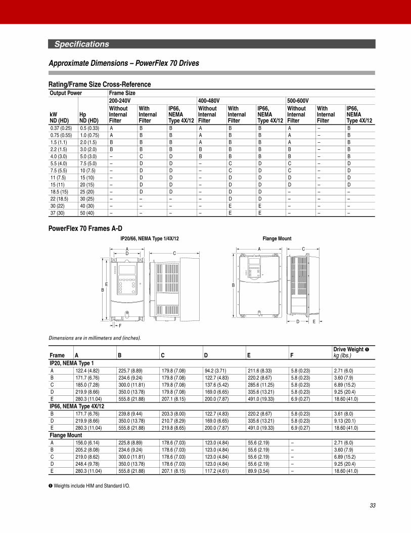
Specifications
Approximate Dimensions – PowerFlex 70 Drives
Rating/Frame Size Cross-Reference
PowerFlex 70 Frames A-D
Dimensions are in millimeters and (inches).
➊ Weights include HIM and Standard I/O.
Output Power Frame Size
kW ND (HD)
Hp ND (HD)
200-240V 400-480V 500-600VWithout Internal Filter
With Internal Filter
IP66, NEMA Type 4X/12
Without Internal Filter
With Internal Filter
IP66, NEMA Type 4X/12
Without Internal Filter
With Internal Filter
IP66, NEMA Type 4X/12
0.37 (0.25) 0.5 (0.33) A B B A B B A – B0.75 (0.55) 1.0 (0.75) A B B A B B A – B1.5 (1.1) 2.0 (1.5) B B B A B B A – B2.2 (1.5) 3.0 (2.0) B B B B B B B – B4.0 (3.0) 5.0 (3.0) – C D B B B B – B5.5 (4.0) 7.5 (5.0) – D D – C D C – D7.5 (5.5) 10 (7.5) – D D – C D C – D11 (7.5) 15 (10) – D D – D D D – D15 (11) 20 (15) – D D – D D D – D18.5 (15) 25 (20) – D D – D D – – –22 (18.5) 30 (25) – – – – D D – – –30 (22) 40 (30) – – – – E E – – –37 (30) 50 (40) – – – – E E – – –
Frame A B C D E FDrive Weight ➊kg (lbs.)
IP20, NEMA Type 1A 122.4 (4.82) 225.7 (8.89) 179.8 (7.08) 94.2 (3.71) 211.6 (8.33) 5.8 (0.23) 2.71 (6.0)B 171.7 (6.76) 234.6 (9.24) 179.8 (7.08) 122.7 (4.83) 220.2 (8.67) 5.8 (0.23) 3.60 (7.9)C 185.0 (7.28) 300.0 (11.81) 179.8 (7.08) 137.6 (5.42) 285.6 (11.25) 5.8 (0.23) 6.89 (15.2)D 219.9 (8.66) 350.0 (13.78) 179.8 (7.08) 169.0 (6.65) 335.6 (13.21) 5.8 (0.23) 9.25 (20.4)E 280.3 (11.04) 555.8 (21.88) 207.1 (8.15) 200.0 (7.87) 491.0 (19.33) 6.9 (0.27) 18.60 (41.0)IP66, NEMA Type 4X/12B 171.7 (6.76) 239.8 (9.44) 203.3 (8.00) 122.7 (4.83) 220.2 (8.67) 5.8 (0.23) 3.61 (8.0)D 219.9 (8.66) 350.0 (13.78) 210.7 (8.29) 169.0 (6.65) 335.6 (13.21) 5.8 (0.23) 9.13 (20.1)E 280.3 (11.04) 555.8 (21.88) 219.8 (8.65) 200.0 (7.87) 491.0 (19.33) 6.9 (0.27) 18.60 (41.0)Flange MountA 156.0 (6.14) 225.8 (8.89) 178.6 (7.03) 123.0 (4.84) 55.6 (2.19) – 2.71 (6.0)B 205.2 (8.08) 234.6 (9.24) 178.6 (7.03) 123.0 (4.84) 55.6 (2.19) – 3.60 (7.9)C 219.0 (8.62) 300.0 (11.81) 178.6 (7.03) 123.0 (4.84) 55.6 (2.19) – 6.89 (15.2)D 248.4 (9.78) 350.0 (13.78) 178.6 (7.03) 123.0 (4.84) 55.6 (2.19) – 9.25 (20.4)E 280.3 (11.04) 555.8 (21.88) 207.1 (8.15) 117.2 (4.61) 89.9 (3.54) – 18.60 (41.0)
A
EB
D
F
C
B
A C
D E
IP20/66, NEMA Type 1/4X/12 Flange Mount
33
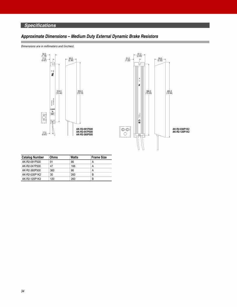
Specifications
Approximate Dimensions – Medium Duty External Dynamic Brake Resistors
Dimensions are in millimeters and (inches).
Catalog Number Ohms Watts Frame SizeAK-R2-091P500 91 86 AAK-R2-047P500 47 166 AAK-R2-360P500 360 86 AAK-R2-030P1K2 30 260 BAK-R2-120P1K2 120 260 B
335.0(13.19)
60.0(2.36)
30.0(1.18)17.0
(0.67)59.0
(2.32)
17.0(0.67)
405.0(15.94)
386.0(15.20)
316.0(12.44)
61.0(2.40)
31.0(1.22)
RO
CK
WE
LL
AU
TOM
ATI
ON
CUS
SURFACES MAY BE
RO
CK
WE
LLA
UTO
MA
TIO
NC
US
AK-R2-091P500AK-R2-047P500AK-R2-360P500
AK-R2-030P1K2AK-R2-120P1K2
34

Notes
35

www.rockwellautomation.com
Corporate HeadquartersRockwell Automation, 777 East Wisconsin Avenue, Suite 1400, Milwaukee, WI, 53202-5302 USA, Tel: (1) 414.212.5200, Fax: (1) 414.212.5201
Headquarters for Allen-Bradley Products, Rockwell Software Products and Global Manufacturing SolutionsAmericas: Rockwell Automation, 1201 South Second Street, Milwaukee, WI 53204-2496 USA, Tel: (1) 414.382.2000, Fax: (1) 414.382.4444Europe/Middle East/Africa: Rockwell Automation SA/NV, Vorstlaan/Boulevard du Souverain 36, 1170 Brussels, Belgium, Tel: (32) 2 663 0600, Fax: (32) 2 663 0640Asia Pacific: Rockwell Automation, Level 14, Core F, Cyberport 3, 100 Cyberport Road, Hong Kong, Tel: (852) 2887 4788, Fax: (852) 2508 1846
Headquarters for Dodge and Reliance Electric ProductsAmericas: Rockwell Automation, 6040 Ponders Court, Greenville, SC 29615-4617 USA, Tel: (1) 864.297.4800, Fax: (1) 864.281.2433Europe/Middle East/Africa: Rockwell Automation, Herman-Heinrich-Gossen-Strasse 3, 50858 Köln, Germany, Tel: 49 (0) 2234 379410, Fax: 49 (0) 2234 3794164Asia Pacific: Rockwell Automation, 55 Newton Road, #11-01/02 Revenue House, Singapore 307987, Tel: (65) 6356-9077, Fax: (65) 6356-9011
U.S. Allen-Bradley Drives Technical SupportTel: (1) 262.512.8176, Fax: (1) 262.512.2222, Email: [email protected], Online: www.ab.com/support/abdrives
PowerFlex, DriveExplorer and DriveTools SP are trademarks of Rockwell Automation.Trademarks not belonging to Rockwell Automation are property of their respective companies.
The Allen-Bradley PowerFlex family of AC drives provides a single-source solution for virtually any drive application requirement ranging from 0.2 to 6,770 kW (0.25 to 8,500 hp). Significant commonality across multiple platforms including networks, operator interface, programming and hardware make PowerFlex drives easy to start up, operate and maintain. Multi-lingual programming, operator interface text and voltage-sensitive defaults in PowerFlex drives will help global OEMs and end-users save time and money during set-up, integration and maintenance of virtually any automation system.
Rockwell Automation supports drive users whenever and wherever needed, providing drive specialists and manufacturing expertise for unmatched service and support around the globe. In fact, one of every five Rockwell Automation employees is in the field with users every day. Rockwell Automation also offers a full spectrum of value-added services and expertise to help simplify maintenance and enhance productivity.
Rockwell Automation is committed to helping its customers meet ever-changing demands. PowerFlex drives illustrate our commitment to user productivity through timely delivery of world-class products and continued backward compatibility to minimize life-cycle costs. Count on Rockwell Automation to be your Complete Automation™ partner – now and in the future.
For further information on PowerFlex drives visit our web site at: www.abpowerflex.com
Publication 20A-TD001G-EN-P — May 2005Supersedes 20A-TD001F-EN-P — January 2005 Copyright ® 2005 Rockwell Automation, Inc. All rights reserved. Printed in USA.