Embed Size (px)
Citation preview
09/09/2010 Rev. 9
Power Flame Incorporated
Director® SCS Supervisory Control System
Instruction Manual
2
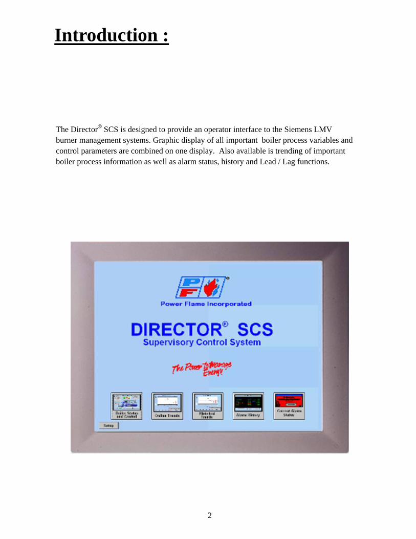
Introduction :
The Director® SCS is designed to provide an operator interface to the Siemens LMV burner management systems. Graphic display of all important boiler process variables and control parameters are combined on one display. Also available is trending of important boiler process information as well as alarm status, history and Lead / Lag functions.
3
Navigating the Director SCS :
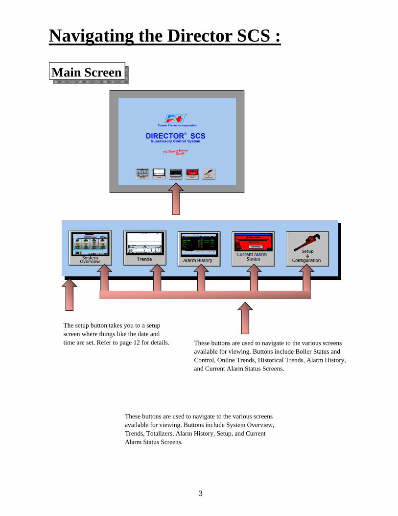
Main Screen
These buttons are used to navigate to the various screens available for viewing. Buttons include System Overview, Trends, Totalizers, Alarm History, Setup, and Current Alarm Status Screens.
These buttons are used to navigate to the various screens available for viewing. Buttons include Boiler Status and Control, Online Trends, Historical Trends, Alarm History, and Current Alarm Status Screens.
The setup button takes you to a setup screen where things like the date and time are set. Refer to page 12 for details.
4
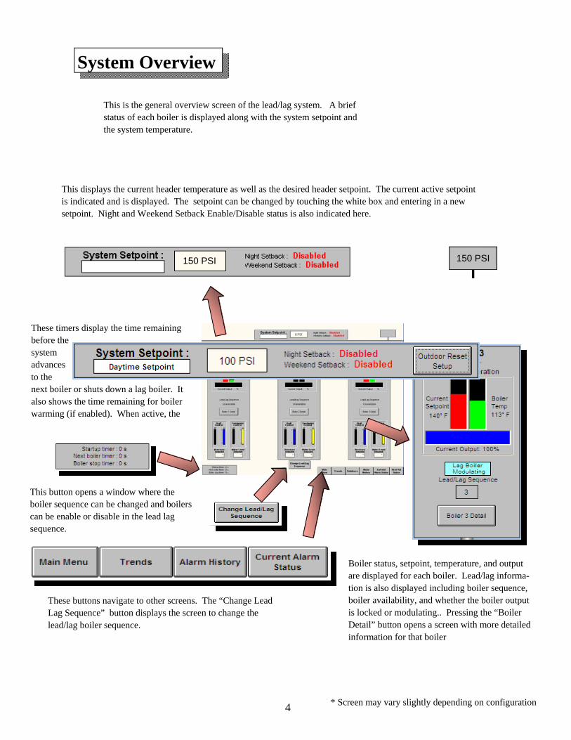
System Overview
* Screen may vary slightly depending on configuration
This is the general overview screen of the lead/lag system. A brief status of each boiler is displayed along with the system setpoint and the system temperature.
Boiler status, setpoint, temperature, and output are displayed for each boiler. Lead/lag informa-tion is also displayed including boiler sequence, boiler availability, and whether the boiler output is locked or modulating.. Pressing the “Boiler Detail” button opens a screen with more detailed information for that boiler
This displays the current header temperature as well as the desired header setpoint. The current active setpoint is indicated and is displayed. The setpoint can be changed by touching the white box and entering in a new setpoint. Night and Weekend Setback Enable/Disable status is also indicated here.
These timers display the time remaining before the system advances to the next boiler or shuts down a lag boiler. It also shows the time remaining for boiler warming (if enabled). When active, the
These buttons navigate to other screens. The “Change Lead Lag Sequence” button displays the screen to change the lead/lag boiler sequence.
This button opens a window where the boiler sequence can be changed and boilers can be enable or disable in the lead lag sequence.
150 PSI 150 PSI
5
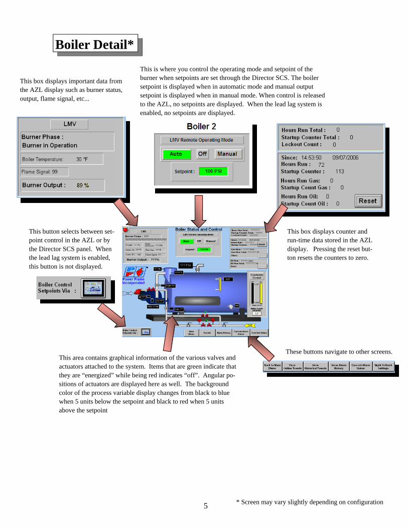
Boiler Detail*
* Screen may vary slightly depending on configuration
This is where you control the operating mode and setpoint of the burner when setpoints are set through the Director SCS. The boiler setpoint is displayed when in automatic mode and manual output setpoint is displayed when in manual mode. When control is released to the AZL, no setpoints are displayed. When the lead lag system is enabled, no setpoints are displayed.
This box displays important data from the AZL display such as burner status, output, flame signal, etc...
This button selects between set-point control in the AZL or by the Director SCS panel. When the lead lag system is enabled, this button is not displayed.
These buttons navigate to other screens. This area contains graphical information of the various valves and actuators attached to the system. Items that are green indicate that they are “energized” while being red indicates “off”. Angular po-sitions of actuators are displayed here as well. The background color of the process variable display changes from black to blue when 5 units below the setpoint and black to red when 5 units above the setpoint
This box displays counter and run-time data stored in the AZL display. Pressing the reset but-ton resets the counters to zero.
6
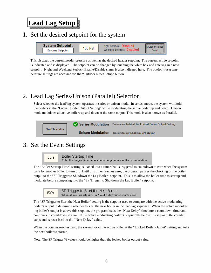
Lead Lag Setup
3. Set the Event Settings
The “Boiler Startup Time” setting is loaded into a timer that is triggered to countdown to zero when the system calls for another boiler to turn on. Until this timer reaches zero, the program pauses the checking of the boiler output to the “SP Trigger to Shutdown the Lag Boiler” setpoint. This is to allow the boiler time to startup and modulate before comparing it to the “SP Trigger to Shutdown the Lag Boiler” setpoint.
The “SP Trigger to Start the Next Boiler” setting is the setpoint used to compare with the active modulating boiler’s output to determine whether to start the next boiler in the lead/lag sequence. When the active modulat-ing boiler’s output is above this setpoint, the program loads the “Next Delay” time into a countdown timer and continues to countdown to zero. If the active modulating boiler’s output falls below this setpoint, the counter stops and is reset back to the “Next Delay” value.
When the counter reaches zero, the system locks the active boiler at the “Locked Boiler Output” setting and tells the next boiler to startup.
Note: The SP Trigger % value should be higher than the locked boiler output value.
2. Lead Lag Series/Unison (Parallel) Selection Select whether the lead/lag system operates in series or unison mode. In series mode, the system will hold the boilers at the “Locked Boiler Output Setting” while modulating the active boiler up and down. Unison mode modulates all active boilers up and down at the same output. This mode is also known as Parallel.
1. Set the desired setpoint for the system
This displays the current header pressure as well as the desired header setpoint. The current active setpoint is indicated and is displayed. The setpoint can be changed by touching the white box and entering in a new setpoint. Night and Weekend Setback Enable/Disable status is also indicated here. The outdoor reset tem-perature settings are accessed via the “Outdoor Reset Setup” button.
7
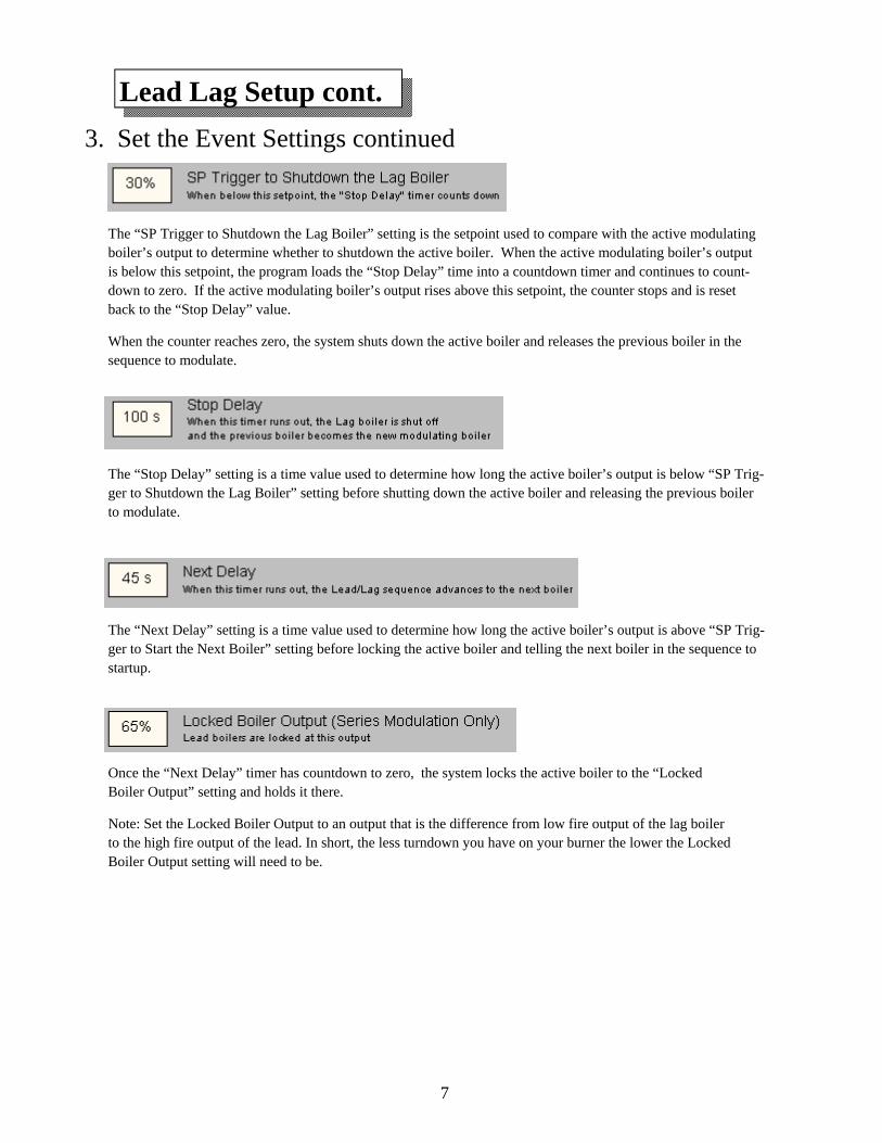
3. Set the Event Settings continued
The “Stop Delay” setting is a time value used to determine how long the active boiler’s output is below “SP Trig-ger to Shutdown the Lag Boiler” setting before shutting down the active boiler and releasing the previous boiler to modulate.
Lead Lag Setup cont.
The “Next Delay” setting is a time value used to determine how long the active boiler’s output is above “SP Trig-ger to Start the Next Boiler” setting before locking the active boiler and telling the next boiler in the sequence to startup.
Once the “Next Delay” timer has countdown to zero, the system locks the active boiler to the “Locked Boiler Output” setting and holds it there.
Note: Set the Locked Boiler Output to an output that is the difference from low fire output of the lag boiler to the high fire output of the lead. In short, the less turndown you have on your burner the lower the Locked Boiler Output setting will need to be.
The “SP Trigger to Shutdown the Lag Boiler” setting is the setpoint used to compare with the active modulating boiler’s output to determine whether to shutdown the active boiler. When the active modulating boiler’s output is below this setpoint, the program loads the “Stop Delay” time into a countdown timer and continues to count-down to zero. If the active modulating boiler’s output rises above this setpoint, the counter stops and is reset back to the “Stop Delay” value.
When the counter reaches zero, the system shuts down the active boiler and releases the previous boiler in the sequence to modulate.
8
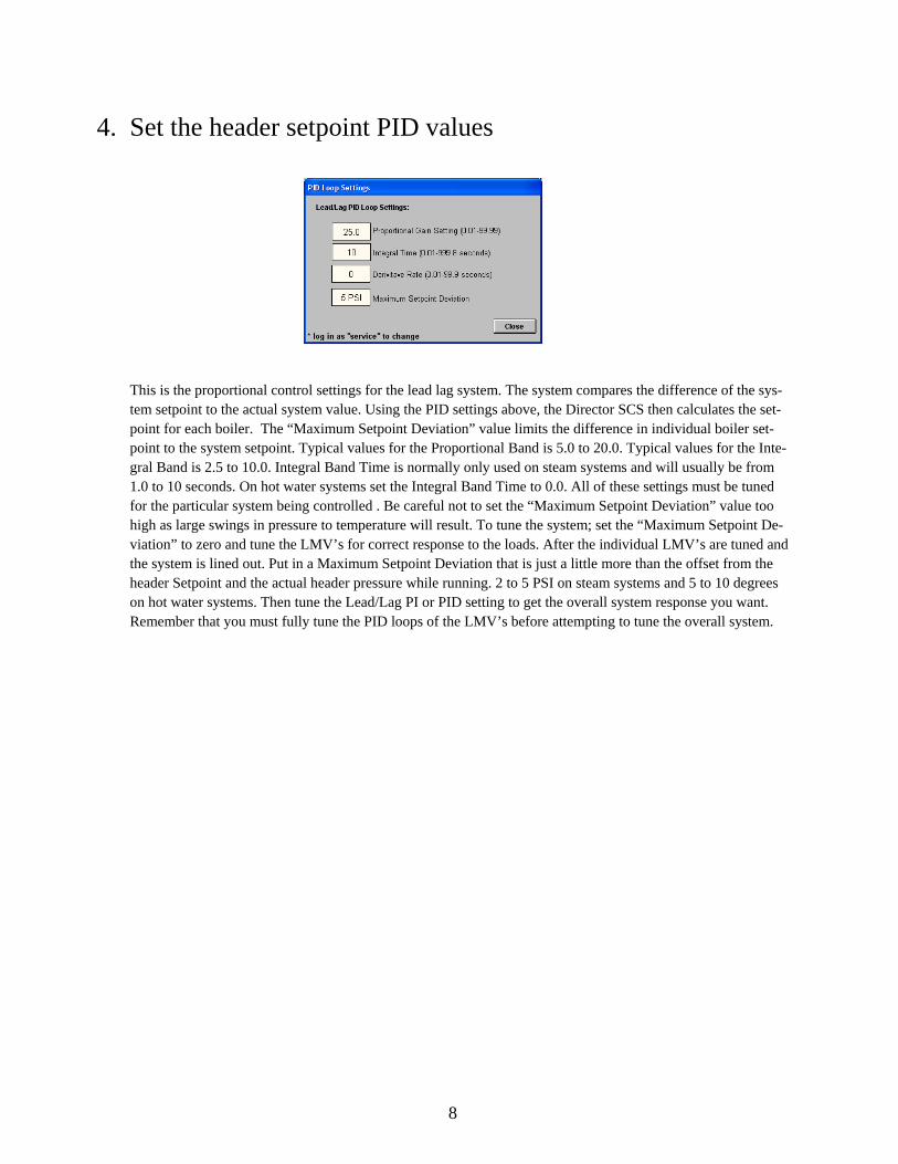
This is the proportional control settings for the lead lag system. The system compares the difference of the sys-tem setpoint to the actual system value. Using the PID settings above, the Director SCS then calculates the set-point for each boiler. The “Maximum Setpoint Deviation” value limits the difference in individual boiler set-point to the system setpoint. Typical values for the Proportional Band is 5.0 to 20.0. Typical values for the Inte-gral Band is 2.5 to 10.0. Integral Band Time is normally only used on steam systems and will usually be from 1.0 to 10 seconds. On hot water systems set the Integral Band Time to 0.0. All of these settings must be tuned for the particular system being controlled . Be careful not to set the “Maximum Setpoint Deviation” value too high as large swings in pressure to temperature will result. To tune the system; set the “Maximum Setpoint De-viation” to zero and tune the LMV’s for correct response to the loads. After the individual LMV’s are tuned and the system is lined out. Put in a Maximum Setpoint Deviation that is just a little more than the offset from the header Setpoint and the actual header pressure while running. 2 to 5 PSI on steam systems and 5 to 10 degrees on hot water systems. Then tune the Lead/Lag PI or PID setting to get the overall system response you want. Remember that you must fully tune the PID loops of the LMV’s before attempting to tune the overall system.
4. Set the header setpoint PID values
9
Lead Lag Setup cont.
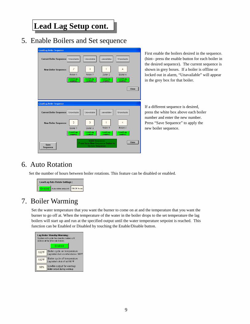
5. Enable Boilers and Set sequence
6. Auto Rotation Set the number of hours between boiler rotations. This feature can be disabled or enabled.
7. Boiler Warming Set the water temperature that you want the burner to come on at and the temperature that you want the burner to go off at. When the temperature of the water in the boiler drops to the set temperature the lag boilers will start up and run at the specified output until the water temperature setpoint is reached. This function can be Enabled or Disabled by touching the Enable/Disable button.
First enable the boilers desired in the sequence. (hint– press the enable button for each boiler in the desired sequence). The current sequence is shown in grey boxes. If a boiler is offline or locked out in alarm, “Unavailable” will appear in the grey box for that boiler.
If a different sequence is desired, press the white box above each boiler number and enter the new number. Press “Save Sequence” to apply the new boiler sequence.
10
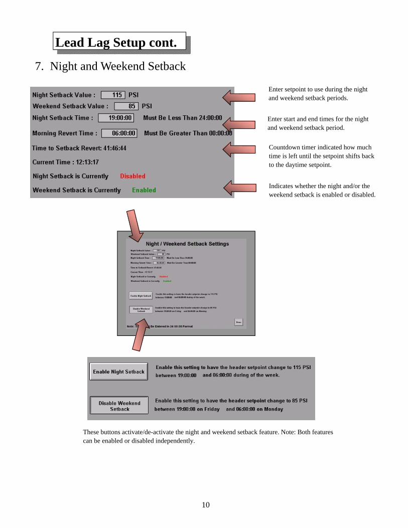
Enter setpoint to use during the night and weekend setback periods.
Enter start and end times for the night and weekend setback period.
Countdown timer indicated how much time is left until the setpoint shifts back to the daytime setpoint.
Indicates whether the night and/or the weekend setback is enabled or disabled.
These buttons activate/de-activate the night and weekend setback feature. Note: Both features can be enabled or disabled independently.
7. Night and Weekend Setback
Lead Lag Setup cont.
11
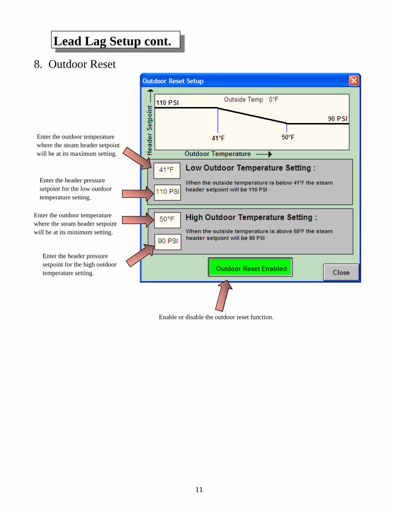
Enter the outdoor temperature where the steam header setpoint will be at its maximum setting.
Enable or disable the outdoor reset function.
8. Outdoor Reset
Lead Lag Setup cont.
Enter the outdoor temperature where the steam header setpoint will be at its minimum setting.
Enter the header pressure setpoint for the low outdoor temperature setting.
Enter the header pressure setpoint for the high outdoor temperature setting.
12
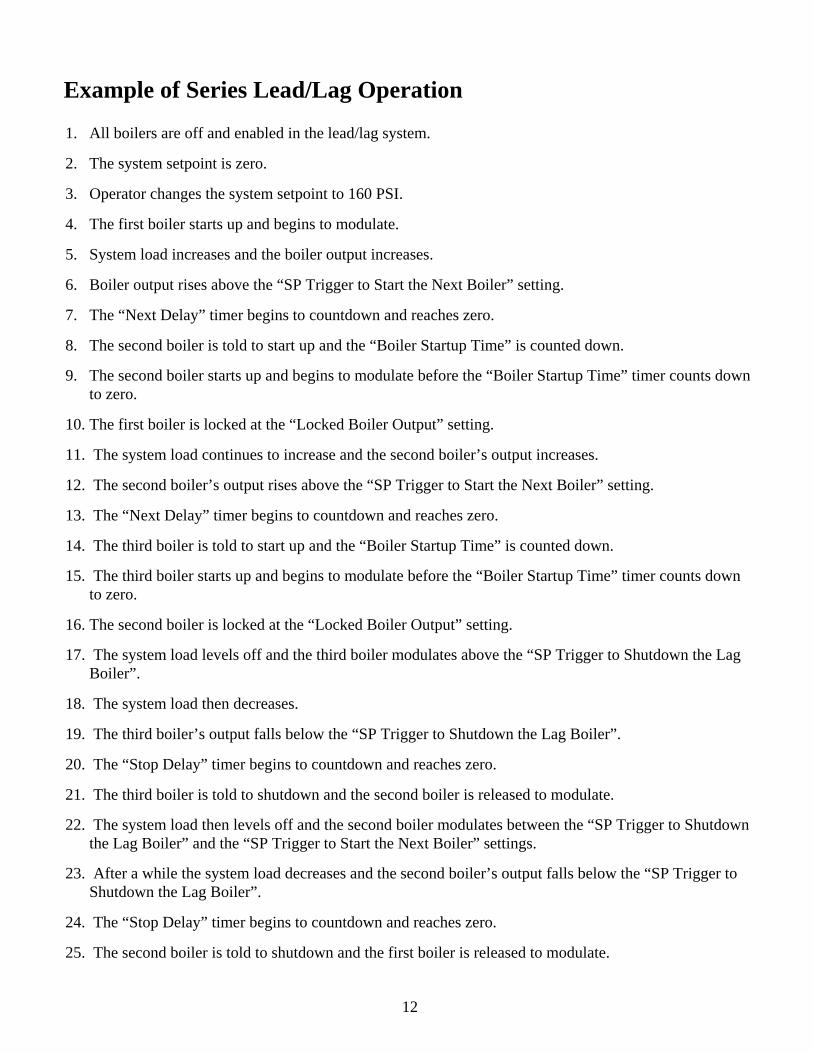
Example of Series Lead/Lag Operation
1. All boilers are off and enabled in the lead/lag system.
2. The system setpoint is zero.
3. Operator changes the system setpoint to 160 PSI.
4. The first boiler starts up and begins to modulate.
5. System load increases and the boiler output increases.
6. Boiler output rises above the “SP Trigger to Start the Next Boiler” setting.
7. The “Next Delay” timer begins to countdown and reaches zero.
8. The second boiler is told to start up and the “Boiler Startup Time” is counted down.
9. The second boiler starts up and begins to modulate before the “Boiler Startup Time” timer counts down to zero.
10. The first boiler is locked at the “Locked Boiler Output” setting.
11. The system load continues to increase and the second boiler’s output increases.
12. The second boiler’s output rises above the “SP Trigger to Start the Next Boiler” setting.
13. The “Next Delay” timer begins to countdown and reaches zero.
14. The third boiler is told to start up and the “Boiler Startup Time” is counted down.
15. The third boiler starts up and begins to modulate before the “Boiler Startup Time” timer counts down to zero.
16. The second boiler is locked at the “Locked Boiler Output” setting.
17. The system load levels off and the third boiler modulates above the “SP Trigger to Shutdown the Lag Boiler”.
18. The system load then decreases.
19. The third boiler’s output falls below the “SP Trigger to Shutdown the Lag Boiler”.
20. The “Stop Delay” timer begins to countdown and reaches zero.
21. The third boiler is told to shutdown and the second boiler is released to modulate.
22. The system load then levels off and the second boiler modulates between the “SP Trigger to Shutdown the Lag Boiler” and the “SP Trigger to Start the Next Boiler” settings.
23. After a while the system load decreases and the second boiler’s output falls below the “SP Trigger to Shutdown the Lag Boiler”.
24. The “Stop Delay” timer begins to countdown and reaches zero.
25. The second boiler is told to shutdown and the first boiler is released to modulate.
13
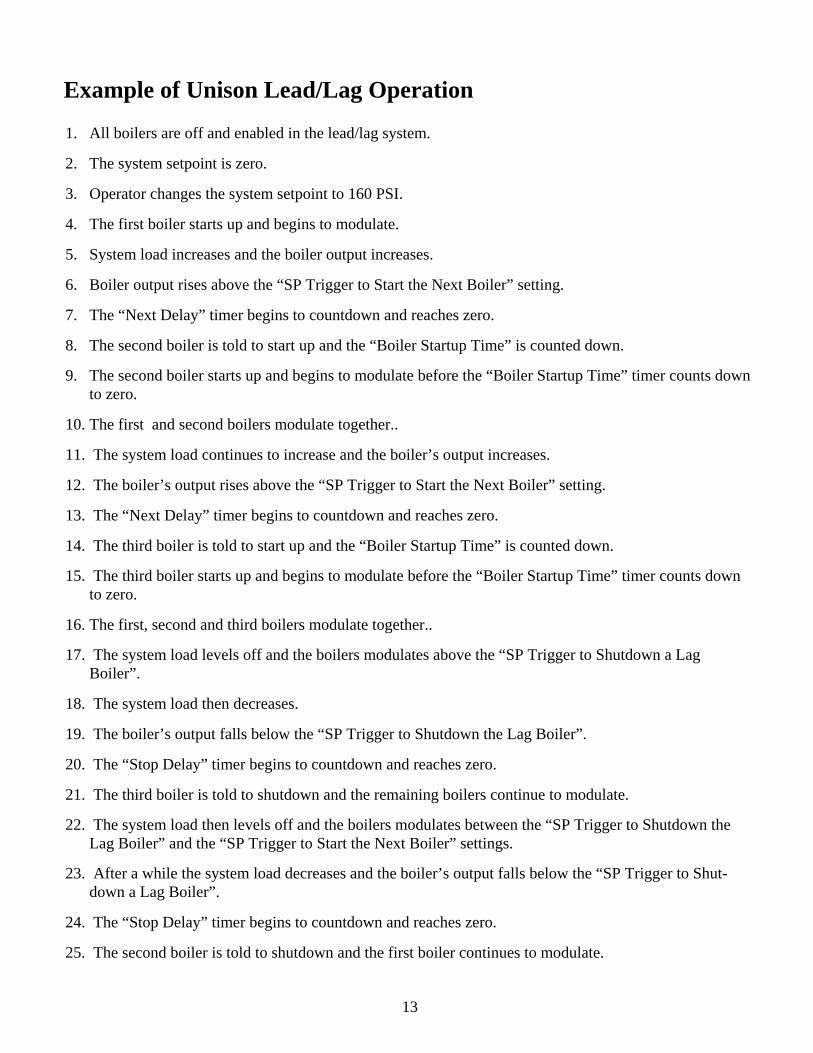
Example of Unison Lead/Lag Operation
1. All boilers are off and enabled in the lead/lag system.
2. The system setpoint is zero.
3. Operator changes the system setpoint to 160 PSI.
4. The first boiler starts up and begins to modulate.
5. System load increases and the boiler output increases.
6. Boiler output rises above the “SP Trigger to Start the Next Boiler” setting.
7. The “Next Delay” timer begins to countdown and reaches zero.
8. The second boiler is told to start up and the “Boiler Startup Time” is counted down.
9. The second boiler starts up and begins to modulate before the “Boiler Startup Time” timer counts down to zero.
10. The first and second boilers modulate together..
11. The system load continues to increase and the boiler’s output increases.
12. The boiler’s output rises above the “SP Trigger to Start the Next Boiler” setting.
13. The “Next Delay” timer begins to countdown and reaches zero.
14. The third boiler is told to start up and the “Boiler Startup Time” is counted down.
15. The third boiler starts up and begins to modulate before the “Boiler Startup Time” timer counts down to zero.
16. The first, second and third boilers modulate together..
17. The system load levels off and the boilers modulates above the “SP Trigger to Shutdown a Lag Boiler”.
18. The system load then decreases.
19. The boiler’s output falls below the “SP Trigger to Shutdown the Lag Boiler”.
20. The “Stop Delay” timer begins to countdown and reaches zero.
21. The third boiler is told to shutdown and the remaining boilers continue to modulate.
22. The system load then levels off and the boilers modulates between the “SP Trigger to Shutdown the Lag Boiler” and the “SP Trigger to Start the Next Boiler” settings.
23. After a while the system load decreases and the boiler’s output falls below the “SP Trigger to Shut-down a Lag Boiler”.
24. The “Stop Delay” timer begins to countdown and reaches zero.
25. The second boiler is told to shutdown and the first boiler continues to modulate.
14
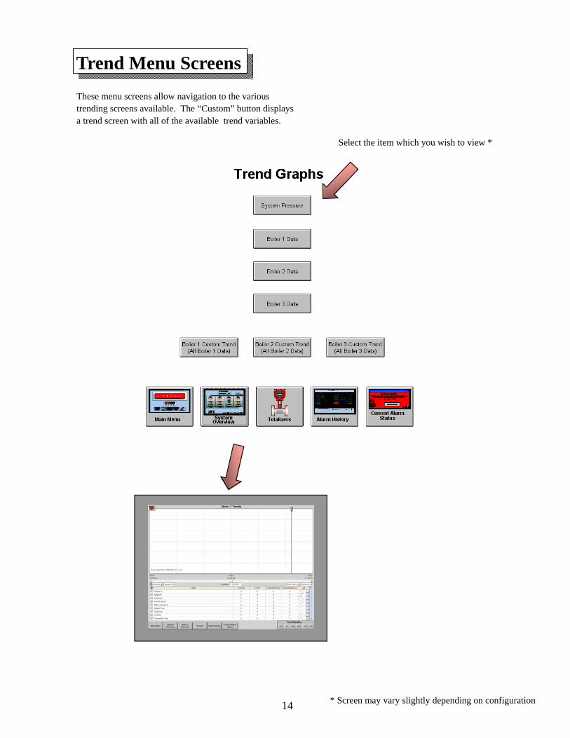
Trend Menu Screens
Select the item which you wish to view *
* Screen may vary slightly depending on configuration
These menu screens allow navigation to the various trending screens available. The “Custom” button displays a trend screen with all of the available trend variables.
15
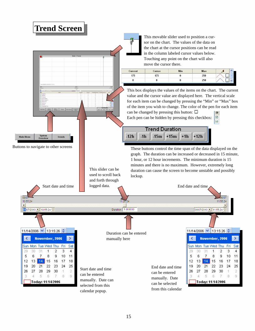
Trend Screen This movable slider used to position a cur-sor on the chart. The values of the data on the chart at the cursor positions can be read in the column labeled cursor values below. Touching any point on the chart will also move the cursor there.
This box displays the values of the items on the chart. The current value and the cursor value are displayed here. The vertical scale for each item can be changed by pressing the “Min” or “Max” box of the item you wish to change. The color of the pen for each item can be changed by pressing this button: Each pen can be hidden by pressing this checkbox:
Buttons to navigate to other screens These buttons control the time span of the data displayed on the graph. The duration can be increased or decreased in 15 minute, 1 hour, or 12 hour increments. The minimum duration is 15 minutes and there is no maximum. However, extremely long duration can cause the screen to become unstable and possibly lockup.
Start date and time End date and time
End date and time can be entered manually. Date can be selected from this calendar
Duration can be entered manually here
Start date and time can be entered manually. Date can selected from this calendar popup.
This slider can be used to scroll back and forth through logged data.
16
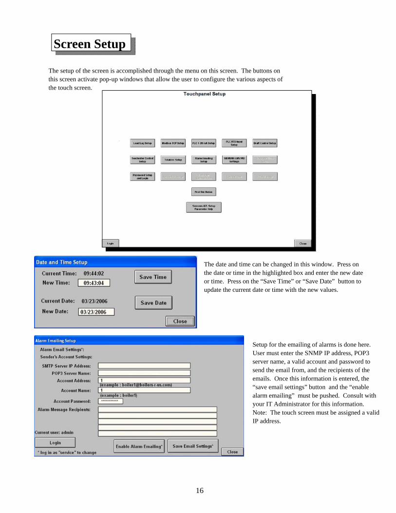
Screen Setup
The date and time can be changed in this window. Press on the date or time in the highlighted box and enter the new date or time. Press on the “Save Time” or “Save Date” button to update the current date or time with the new values.
Setup for the emailing of alarms is done here. User must enter the SNMP IP address, POP3 server name, a valid account and password to send the email from, and the recipients of the emails. Once this information is entered, the “save email settings” button and the “enable alarm emailing” must be pushed. Consult with your IT Administrator for this information. Note: The touch screen must be assigned a valid IP address.
The setup of the screen is accomplished through the menu on this screen. The buttons on this screen activate pop-up windows that allow the user to configure the various aspects of the touch screen.
17
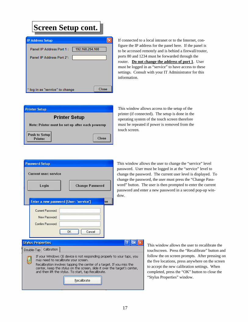
If connected to a local intranet or to the Internet, con-figure the IP address for the panel here. If the panel is to be accessed remotely and is behind a firewall/router, ports 80 and 1234 must be forwarded through the router. Do not change the address of port 1. User must be logged in as “service” to have access to these settings. Consult with your IT Administrator for this information.
Screen Setup cont.
This window allows access to the setup of the printer (if connected). The setup is done in the operating system of the touch screen therefore must be repeated if power is removed from the touch screen.
This window allows the user to change the “service” level password. User must be logged in at the “service” level to change the password. The current user level is displayed. To change the password, the user must press the “Change Pass-word” button. The user is then prompted to enter the current password and enter a new password in a second pop-up win-dow.
This window allows the user to recalibrate the touchscreen. Press the “Recalibrate” button and follow the on screen prompts. After pressing on the five locations, press anywhere on the screen to accept the new calibration settings. When completed, press the “OK” button to close the “Stylus Properties” window.
18
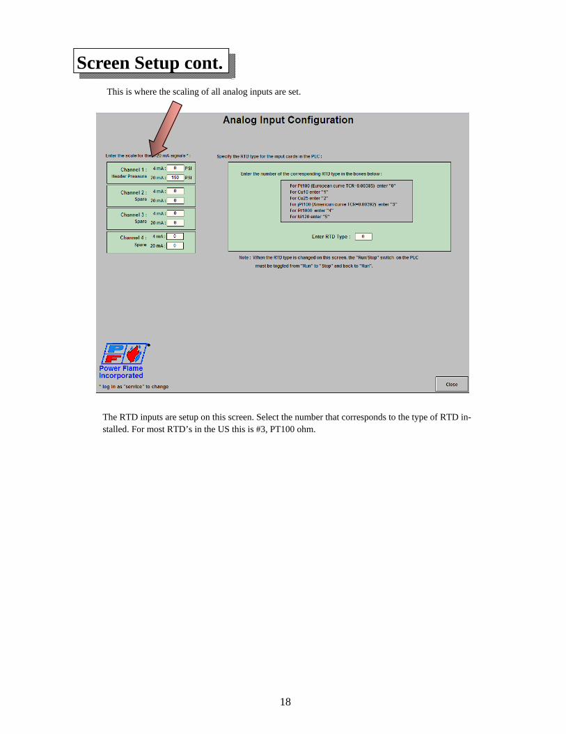
Screen Setup cont.
The RTD inputs are setup on this screen. Select the number that corresponds to the type of RTD in-stalled. For most RTD’s in the US this is #3, PT100 ohm.
This is where the scaling of all analog inputs are set.
19
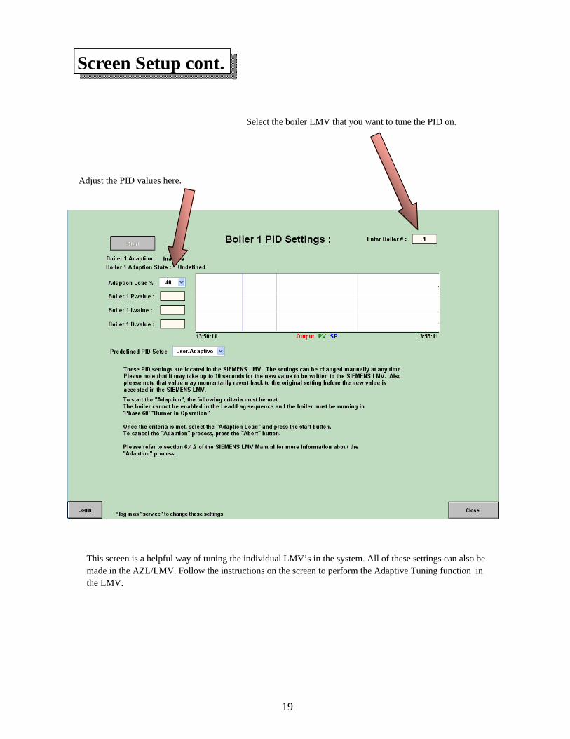
Screen Setup cont.
This screen is a helpful way of tuning the individual LMV’s in the system. All of these settings can also be made in the AZL/LMV. Follow the instructions on the screen to perform the Adaptive Tuning function in the LMV.
Select the boiler LMV that you want to tune the PID on.
Adjust the PID values here.
20
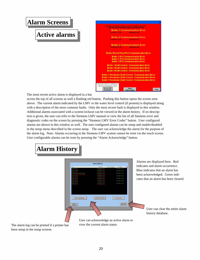
Alarm Screens
The most recent active alarm is displayed in a bar across the top of all screens as well a flashing red button. Pushing this button opens the screen seen above. The current alarm indicated by the LMV or the water level control (if present) is displayed along with a description of the most common faults. Only the most recent fault is displayed in this window. Additional alarms associated with a system lockout can be viewed in the alarm history. If no descrip-tion is given, the user can refer to the Siemens LMV manual or view the list of all Siemens error and diagnostic codes on the screen by pressing the “Siemens LMV Error Codes” button. User configured alarms are shown in this window as well. The user configured alarms can be setup and enable/disabled in the setup menu described in the screen setup. The user can acknowledge the alarm for the purpose of the alarm log. Note: Alarms occurring in the Siemens LMV system cannot be reset via the touch screen. User configurable alarms can be reset by pressing the “Alarm Acknowledge” button.
Alarm History
Active alarms
Alarms are displayed here. Red indicates and alarm occurrence. Blue indicates that an alarm has been acknowledged. Green indi-cates that an alarm has been cleared.
User can acknowledge an active alarm or view the current alarm status The alarm log can be printed if a printer has
been setup in the setup screens
User can clear the entire alarm history database.
21
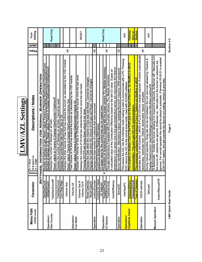
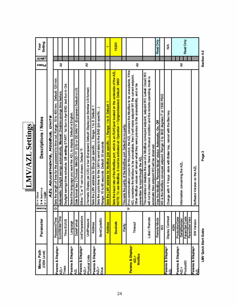
LMV Setting Notes The following pages show the basic communication settings for the LMV to communicate with the Director SCS. However there are several other considerations that should be given when using the Director SCS in a Lead Lag system.
1) Make sure the Modbus “Timeout” setting is set to 30 seconds. This is the factory default.
2) Set the W1 setpoint in the LMV/AZL to be about the same as your running pressure or temperature. This will allow the boiler to remain running on this local setpoint should the communication be lost to the Director SCS. On lead/lag systems the W1 setpoints may be set a little higher on one boiler and lower on another to provide basic sequencing.
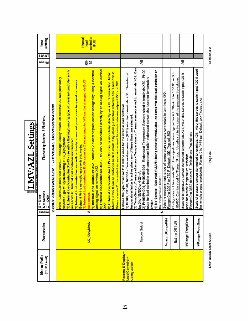
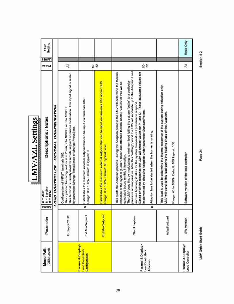
3) The External Maximum Setpoint must be set so the Director SCS can send a high enough setpoint to the LMV during operation. This setting is found under Params & Display > Load Controller > Configuration > Ext MaxSetpoint. This setting limits the setpoint W3 setpoint used by the Director SCS. It is set as a percentage of the measured variable input span of the LMV.
4) When enabling the GatewayBASon from the AZL you must press the Enter button on the AZL while the GatewayBASon parameter is highlighted. There will be no feedback on the AZL as to the state of the Gate-way.
5) Since the Director SCS is using the temperature reading from the Cold Start section of the LMV the Addition-alSens must be set to Pt100. This setting is found under Params & Display > Load Controller > Controller Param > Cold Start > AdditionalSens.
22
LM
V/A
ZL
Sett
ings
23
L
MV
/AZ
L Se
ttin
gs
24
LM
V/A
ZL
Sett
ings
25
LM
V/A
ZL
Sett
ings
26
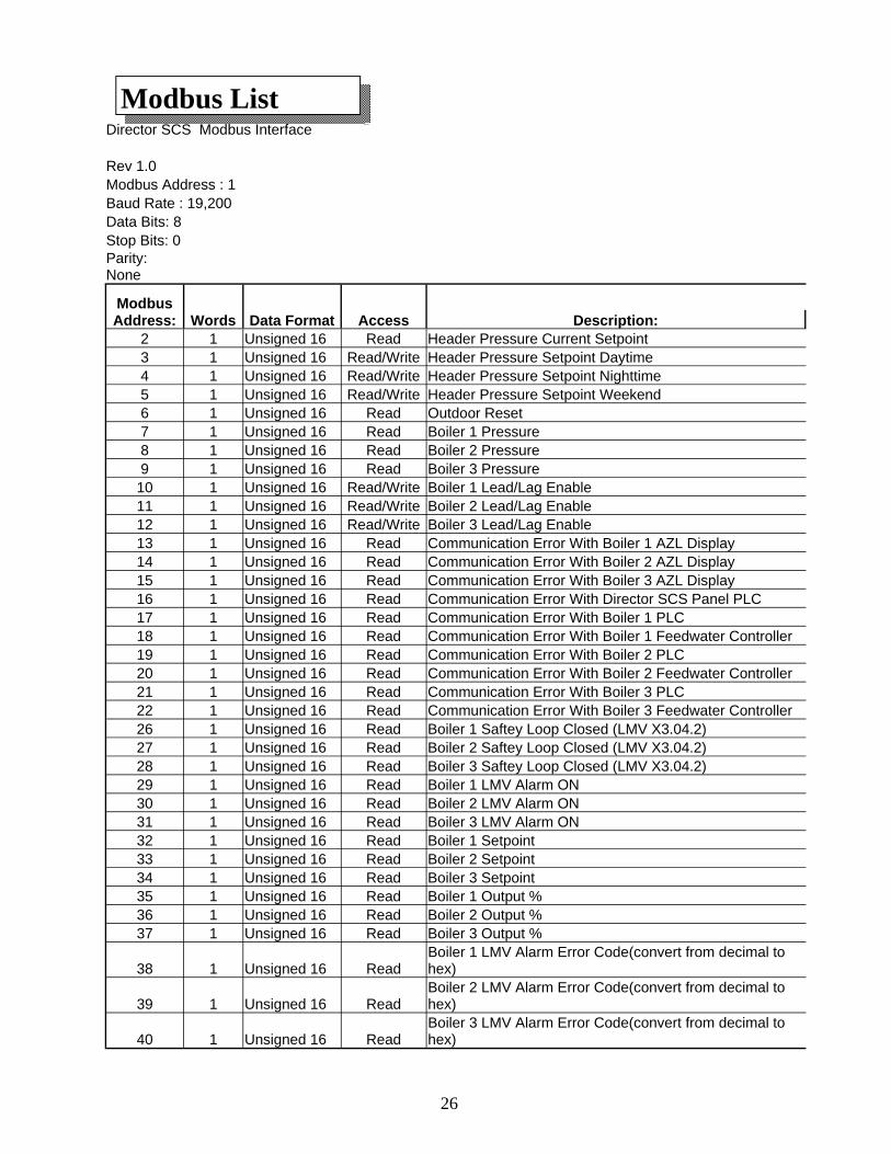
Modbus List Director SCS Modbus Interface Rev 1.0 Modbus Address : 1 Baud Rate : 19,200 Data Bits: 8 Stop Bits: 0 Parity: None
Modbus Address: Words Data Format Access Description:
2 1 Unsigned 16 Read Header Pressure Current Setpoint 3 1 Unsigned 16 Read/Write Header Pressure Setpoint Daytime 4 1 Unsigned 16 Read/Write Header Pressure Setpoint Nighttime 5 1 Unsigned 16 Read/Write Header Pressure Setpoint Weekend 6 1 Unsigned 16 Read Outdoor Reset 7 1 Unsigned 16 Read Boiler 1 Pressure 8 1 Unsigned 16 Read Boiler 2 Pressure 9 1 Unsigned 16 Read Boiler 3 Pressure 10 1 Unsigned 16 Read/Write Boiler 1 Lead/Lag Enable 11 1 Unsigned 16 Read/Write Boiler 2 Lead/Lag Enable 12 1 Unsigned 16 Read/Write Boiler 3 Lead/Lag Enable 13 1 Unsigned 16 Read Communication Error With Boiler 1 AZL Display 14 1 Unsigned 16 Read Communication Error With Boiler 2 AZL Display 15 1 Unsigned 16 Read Communication Error With Boiler 3 AZL Display 16 1 Unsigned 16 Read Communication Error With Director SCS Panel PLC 17 1 Unsigned 16 Read Communication Error With Boiler 1 PLC 18 1 Unsigned 16 Read Communication Error With Boiler 1 Feedwater Controller 19 1 Unsigned 16 Read Communication Error With Boiler 2 PLC 20 1 Unsigned 16 Read Communication Error With Boiler 2 Feedwater Controller 21 1 Unsigned 16 Read Communication Error With Boiler 3 PLC 22 1 Unsigned 16 Read Communication Error With Boiler 3 Feedwater Controller 26 1 Unsigned 16 Read Boiler 1 Saftey Loop Closed (LMV X3.04.2) 27 1 Unsigned 16 Read Boiler 2 Saftey Loop Closed (LMV X3.04.2) 28 1 Unsigned 16 Read Boiler 3 Saftey Loop Closed (LMV X3.04.2) 29 1 Unsigned 16 Read Boiler 1 LMV Alarm ON 30 1 Unsigned 16 Read Boiler 2 LMV Alarm ON 31 1 Unsigned 16 Read Boiler 3 LMV Alarm ON 32 1 Unsigned 16 Read Boiler 1 Setpoint 33 1 Unsigned 16 Read Boiler 2 Setpoint 34 1 Unsigned 16 Read Boiler 3 Setpoint 35 1 Unsigned 16 Read Boiler 1 Output % 36 1 Unsigned 16 Read Boiler 2 Output % 37 1 Unsigned 16 Read Boiler 3 Output %
38 1 Unsigned 16 Read Boiler 1 LMV Alarm Error Code(convert from decimal to hex)
39 1 Unsigned 16 Read Boiler 2 LMV Alarm Error Code(convert from decimal to hex)
40 1 Unsigned 16 Read Boiler 3 LMV Alarm Error Code(convert from decimal to hex)
27
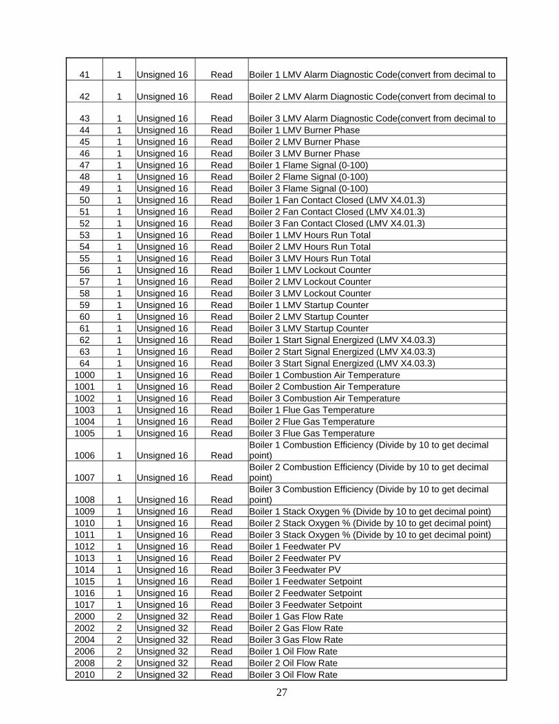
41 1 Unsigned 16 Read Boiler 1 LMV Alarm Diagnostic Code(convert from decimal to
42 1 Unsigned 16 Read Boiler 2 LMV Alarm Diagnostic Code(convert from decimal to
43 1 Unsigned 16 Read Boiler 3 LMV Alarm Diagnostic Code(convert from decimal to 44 1 Unsigned 16 Read Boiler 1 LMV Burner Phase 45 1 Unsigned 16 Read Boiler 2 LMV Burner Phase 46 1 Unsigned 16 Read Boiler 3 LMV Burner Phase 47 1 Unsigned 16 Read Boiler 1 Flame Signal (0-100) 48 1 Unsigned 16 Read Boiler 2 Flame Signal (0-100) 49 1 Unsigned 16 Read Boiler 3 Flame Signal (0-100) 50 1 Unsigned 16 Read Boiler 1 Fan Contact Closed (LMV X4.01.3) 51 1 Unsigned 16 Read Boiler 2 Fan Contact Closed (LMV X4.01.3) 52 1 Unsigned 16 Read Boiler 3 Fan Contact Closed (LMV X4.01.3) 53 1 Unsigned 16 Read Boiler 1 LMV Hours Run Total 54 1 Unsigned 16 Read Boiler 2 LMV Hours Run Total 55 1 Unsigned 16 Read Boiler 3 LMV Hours Run Total 56 1 Unsigned 16 Read Boiler 1 LMV Lockout Counter 57 1 Unsigned 16 Read Boiler 2 LMV Lockout Counter 58 1 Unsigned 16 Read Boiler 3 LMV Lockout Counter 59 1 Unsigned 16 Read Boiler 1 LMV Startup Counter 60 1 Unsigned 16 Read Boiler 2 LMV Startup Counter 61 1 Unsigned 16 Read Boiler 3 LMV Startup Counter 62 1 Unsigned 16 Read Boiler 1 Start Signal Energized (LMV X4.03.3) 63 1 Unsigned 16 Read Boiler 2 Start Signal Energized (LMV X4.03.3) 64 1 Unsigned 16 Read Boiler 3 Start Signal Energized (LMV X4.03.3)
1000 1 Unsigned 16 Read Boiler 1 Combustion Air Temperature 1001 1 Unsigned 16 Read Boiler 2 Combustion Air Temperature 1002 1 Unsigned 16 Read Boiler 3 Combustion Air Temperature 1003 1 Unsigned 16 Read Boiler 1 Flue Gas Temperature 1004 1 Unsigned 16 Read Boiler 2 Flue Gas Temperature 1005 1 Unsigned 16 Read Boiler 3 Flue Gas Temperature
1006 1 Unsigned 16 Read Boiler 1 Combustion Efficiency (Divide by 10 to get decimal point)
1007 1 Unsigned 16 Read Boiler 2 Combustion Efficiency (Divide by 10 to get decimal point)
1008 1 Unsigned 16 Read Boiler 3 Combustion Efficiency (Divide by 10 to get decimal point)
1009 1 Unsigned 16 Read Boiler 1 Stack Oxygen % (Divide by 10 to get decimal point) 1010 1 Unsigned 16 Read Boiler 2 Stack Oxygen % (Divide by 10 to get decimal point) 1011 1 Unsigned 16 Read Boiler 3 Stack Oxygen % (Divide by 10 to get decimal point) 1012 1 Unsigned 16 Read Boiler 1 Feedwater PV 1013 1 Unsigned 16 Read Boiler 2 Feedwater PV 1014 1 Unsigned 16 Read Boiler 3 Feedwater PV 1015 1 Unsigned 16 Read Boiler 1 Feedwater Setpoint 1016 1 Unsigned 16 Read Boiler 2 Feedwater Setpoint 1017 1 Unsigned 16 Read Boiler 3 Feedwater Setpoint 2000 2 Unsigned 32 Read Boiler 1 Gas Flow Rate 2002 2 Unsigned 32 Read Boiler 2 Gas Flow Rate 2004 2 Unsigned 32 Read Boiler 3 Gas Flow Rate 2006 2 Unsigned 32 Read Boiler 1 Oil Flow Rate 2008 2 Unsigned 32 Read Boiler 2 Oil Flow Rate 2010 2 Unsigned 32 Read Boiler 3 Oil Flow Rate