Embed Size (px)
Citation preview

SAP® PowerDesigner®Document Version: 16.5 SP05 – 2015-03-30
PowerDesigner Web
Content
1 PowerDesigner Web. . . . . . . . . . . . . . . . . . . . . . . . . . . . . . . . . . . . . . . . . . . . . . . . . . . . . . . . . . . . 41.1 The Workspace. . . . . . . . . . . . . . . . . . . . . . . . . . . . . . . . . . . . . . . . . . . . . . . . . . . . . . . . . . . . . . . . . 5
Reviewing Diagrams for Publication. . . . . . . . . . . . . . . . . . . . . . . . . . . . . . . . . . . . . . . . . . . . . . . . 71.2 The Repository. . . . . . . . . . . . . . . . . . . . . . . . . . . . . . . . . . . . . . . . . . . . . . . . . . . . . . . . . . . . . . . . . 8
Object Properties. . . . . . . . . . . . . . . . . . . . . . . . . . . . . . . . . . . . . . . . . . . . . . . . . . . . . . . . . . . . . 9Creating a Diagram. . . . . . . . . . . . . . . . . . . . . . . . . . . . . . . . . . . . . . . . . . . . . . . . . . . . . . . . . . . 10Creating a Chart. . . . . . . . . . . . . . . . . . . . . . . . . . . . . . . . . . . . . . . . . . . . . . . . . . . . . . . . . . . . . 11
1.3 The Dashboard. . . . . . . . . . . . . . . . . . . . . . . . . . . . . . . . . . . . . . . . . . . . . . . . . . . . . . . . . . . . . . . . 13Chart Examples. . . . . . . . . . . . . . . . . . . . . . . . . . . . . . . . . . . . . . . . . . . . . . . . . . . . . . . . . . . . . 14
1.4 The Diagram Viewer. . . . . . . . . . . . . . . . . . . . . . . . . . . . . . . . . . . . . . . . . . . . . . . . . . . . . . . . . . . . . 17Editing Diagrams. . . . . . . . . . . . . . . . . . . . . . . . . . . . . . . . . . . . . . . . . . . . . . . . . . . . . . . . . . . . 19Commenting on Diagrams. . . . . . . . . . . . . . . . . . . . . . . . . . . . . . . . . . . . . . . . . . . . . . . . . . . . . . 21Sharing, Exporting, and Reporting on Diagrams. . . . . . . . . . . . . . . . . . . . . . . . . . . . . . . . . . . . . . .23Comparing Diagram Versions. . . . . . . . . . . . . . . . . . . . . . . . . . . . . . . . . . . . . . . . . . . . . . . . . . . 24Verifying Diagrams. . . . . . . . . . . . . . . . . . . . . . . . . . . . . . . . . . . . . . . . . . . . . . . . . . . . . . . . . . . 25Publishing Diagrams. . . . . . . . . . . . . . . . . . . . . . . . . . . . . . . . . . . . . . . . . . . . . . . . . . . . . . . . . . 29Creating Reusable Objects in the Library. . . . . . . . . . . . . . . . . . . . . . . . . . . . . . . . . . . . . . . . . . . 29
1.5 Process Maps. . . . . . . . . . . . . . . . . . . . . . . . . . . . . . . . . . . . . . . . . . . . . . . . . . . . . . . . . . . . . . . . . 30Processes. . . . . . . . . . . . . . . . . . . . . . . . . . . . . . . . . . . . . . . . . . . . . . . . . . . . . . . . . . . . . . . . . 32Architecture Areas. . . . . . . . . . . . . . . . . . . . . . . . . . . . . . . . . . . . . . . . . . . . . . . . . . . . . . . . . . . 35Business Functions. . . . . . . . . . . . . . . . . . . . . . . . . . . . . . . . . . . . . . . . . . . . . . . . . . . . . . . . . . .36
1.6 BPMN 2.0 Descriptive. . . . . . . . . . . . . . . . . . . . . . . . . . . . . . . . . . . . . . . . . . . . . . . . . . . . . . . . . . . 37Pools and Lanes (BPMN Descriptive). . . . . . . . . . . . . . . . . . . . . . . . . . . . . . . . . . . . . . . . . . . . . . 39Start and End Events (BPMN Descriptive). . . . . . . . . . . . . . . . . . . . . . . . . . . . . . . . . . . . . . . . . . 40Tasks (BPMN Descriptive). . . . . . . . . . . . . . . . . . . . . . . . . . . . . . . . . . . . . . . . . . . . . . . . . . . . . .42Gateways (BPMN Descriptive). . . . . . . . . . . . . . . . . . . . . . . . . . . . . . . . . . . . . . . . . . . . . . . . . . .44Data (BPMN Descriptive). . . . . . . . . . . . . . . . . . . . . . . . . . . . . . . . . . . . . . . . . . . . . . . . . . . . . . 47Sequence and Message Flows (BPMN Descriptive). . . . . . . . . . . . . . . . . . . . . . . . . . . . . . . . . . . . 49
1.7 BPMN 2.0 Executable. . . . . . . . . . . . . . . . . . . . . . . . . . . . . . . . . . . . . . . . . . . . . . . . . . . . . . . . . . . 50Collaboration and Process Diagrams (BPMN Executable). . . . . . . . . . . . . . . . . . . . . . . . . . . . . . . .52Conversation Diagrams (BPMN Executable). . . . . . . . . . . . . . . . . . . . . . . . . . . . . . . . . . . . . . . . . 54Choreography Diagrams (BPMN Executable). . . . . . . . . . . . . . . . . . . . . . . . . . . . . . . . . . . . . . . . 56Pools and Lanes (BPMN Executable). . . . . . . . . . . . . . . . . . . . . . . . . . . . . . . . . . . . . . . . . . . . . . 58Start, Intermediate, and End Events (BPMN Executable). . . . . . . . . . . . . . . . . . . . . . . . . . . . . . . . 58Activities (BPMN Executable). . . . . . . . . . . . . . . . . . . . . . . . . . . . . . . . . . . . . . . . . . . . . . . . . . . .61Gateways (BPMN Executable). . . . . . . . . . . . . . . . . . . . . . . . . . . . . . . . . . . . . . . . . . . . . . . . . . . 62
2 © 2015 SAP SE or an SAP affiliate company. All rights reserved.PowerDesigner Web
Content
Data and Data References (BPMN Executable). . . . . . . . . . . . . . . . . . . . . . . . . . . . . . . . . . . . . . . 63Correlation Keys (BPMN Executable). . . . . . . . . . . . . . . . . . . . . . . . . . . . . . . . . . . . . . . . . . . . . . 65Messages (BPMN Executable). . . . . . . . . . . . . . . . . . . . . . . . . . . . . . . . . . . . . . . . . . . . . . . . . . . 65Item-Aware Elements (BPMN Executable). . . . . . . . . . . . . . . . . . . . . . . . . . . . . . . . . . . . . . . . . . 66Sequence and Message Flows (BPMN Executable). . . . . . . . . . . . . . . . . . . . . . . . . . . . . . . . . . . . 67Importing and Exporting BPMN 2.0 Files. . . . . . . . . . . . . . . . . . . . . . . . . . . . . . . . . . . . . . . . . . . .68
1.8 Business Rules. . . . . . . . . . . . . . . . . . . . . . . . . . . . . . . . . . . . . . . . . . . . . . . . . . . . . . . . . . . . . . . . .71Attaching a Business Rule to a Model Object. . . . . . . . . . . . . . . . . . . . . . . . . . . . . . . . . . . . . . . . . 72
2 Administering PowerDesigner Web. . . . . . . . . . . . . . . . . . . . . . . . . . . . . . . . . . . . . . . . . . . . . . . . 742.1 Installing the PowerDesigner Web Server. . . . . . . . . . . . . . . . . . . . . . . . . . . . . . . . . . . . . . . . . . . . . .742.2 Controlling Repository Access. . . . . . . . . . . . . . . . . . . . . . . . . . . . . . . . . . . . . . . . . . . . . . . . . . . . . 78
Creating Repository Users. . . . . . . . . . . . . . . . . . . . . . . . . . . . . . . . . . . . . . . . . . . . . . . . . . . . . 80Creating Repository Groups. . . . . . . . . . . . . . . . . . . . . . . . . . . . . . . . . . . . . . . . . . . . . . . . . . . . 82Granting Rights to Users and Groups. . . . . . . . . . . . . . . . . . . . . . . . . . . . . . . . . . . . . . . . . . . . . . 85Granting Access Permissions on Repository Items. . . . . . . . . . . . . . . . . . . . . . . . . . . . . . . . . . . . 86Unblocking Blocked Users . . . . . . . . . . . . . . . . . . . . . . . . . . . . . . . . . . . . . . . . . . . . . . . . . . . . . 87Deactivating Users. . . . . . . . . . . . . . . . . . . . . . . . . . . . . . . . . . . . . . . . . . . . . . . . . . . . . . . . . . . 87Obtaining Emergency Access to the Repository. . . . . . . . . . . . . . . . . . . . . . . . . . . . . . . . . . . . . . 88
2.3 Creating Custom Properties. . . . . . . . . . . . . . . . . . . . . . . . . . . . . . . . . . . . . . . . . . . . . . . . . . . . . . . 892.4 Configuring the PowerDesigner Web Server. . . . . . . . . . . . . . . . . . . . . . . . . . . . . . . . . . . . . . . . . . . .92
Connecting to the Database Server. . . . . . . . . . . . . . . . . . . . . . . . . . . . . . . . . . . . . . . . . . . . . . . 92Connecting to a License Server. . . . . . . . . . . . . . . . . . . . . . . . . . . . . . . . . . . . . . . . . . . . . . . . . . 93Connecting to an LDAP Server for User Authentication. . . . . . . . . . . . . . . . . . . . . . . . . . . . . . . . . 94Connecting to an SMTP Server for Notifications. . . . . . . . . . . . . . . . . . . . . . . . . . . . . . . . . . . . . . 98Defining a Password Policy. . . . . . . . . . . . . . . . . . . . . . . . . . . . . . . . . . . . . . . . . . . . . . . . . . . . . 99Enabling SSL for PowerDesigner Web. . . . . . . . . . . . . . . . . . . . . . . . . . . . . . . . . . . . . . . . . . . . . 100Enabling Single Sign-On for PowerDesigner Web. . . . . . . . . . . . . . . . . . . . . . . . . . . . . . . . . . . . . 102Configuring Other PowerDesigner Web Parameters. . . . . . . . . . . . . . . . . . . . . . . . . . . . . . . . . . . 104
PowerDesigner WebContent © 2015 SAP SE or an SAP affiliate company. All rights reserved. 3
1 PowerDesigner Web
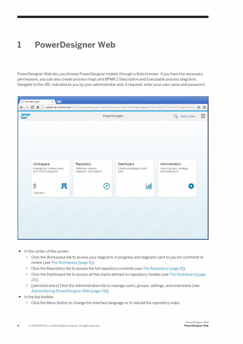
PowerDesigner Web lets you browse PowerDesigner models through a Web browser. If you have the necessary permissions, you can also create process maps and BPMN 2 Descriptive and Executable process diagrams. Navigate to the URL indicated to you by your administrator and, if required, enter your user name and password.
● In the center of the screen:○ Click the Workspace tile to access your diagrams in progress and diagrams sent to you for comment or
review (see The Workspace [page 5]).○ Click the Repository tile to access the full repository contents (see The Repository [page 8]).○ Click the Dashboard tile to access all the charts defined on repository models (see The Dashboard [page
13]).○ [administrators] Click the Administration tile to manage users, groups, settings, and extensions (see
Administering PowerDesigner Web [page 74])● In the top toolbar:
○ Click the Menu button to change the interface language or to rebuild the repository index.
4 © 2015 SAP SE or an SAP affiliate company. All rights reserved.PowerDesigner Web
PowerDesigner Web
NoteThe repository index is rebuilt regularly by the server. In rare situations, where changes that should be visible are not, select Menu Rebuild Index .
○ Click the Search button to search the repository contents.○ Click your name to log out of PowerDesigner Web or to change your password.
PowerDesigner Web works with modern Web browsers. It has been tested with the following browser versions:
● Internet Explorer 10 and 11● Firefox v26 to v35● Chrome v35 to v40● Safari for Mac OS X v10.9 and v10.10● Mobile Safari for iOS v7.1 and v8.1
1.1 The Workspace
The Workspace gives you access to your in-progress diagrams, as well as diagrams sent to you for review or comment, and your recent and favorite diagrams. To access the Workspace, go to the homepage and click the Workspace tile.
PowerDesigner WebPowerDesigner Web © 2015 SAP SE or an SAP affiliate company. All rights reserved. 5
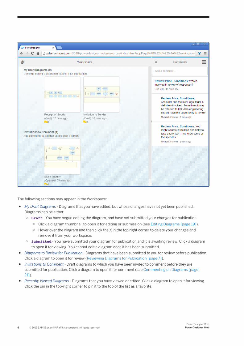
The following sections may appear in the Workspace:
● My Draft Diagrams - Diagrams that you have edited, but whose changes have not yet been published. Diagrams can be either:○ Draft - You have begun editing the diagram, and have not submitted your changes for publication.
○ Click a diagram thumbnail to open it for editing or submission (see Editing Diagrams [page 19]).○ Hover over the diagram and then click the X in the top right corner to delete your changes and
remove it from your workspace.○ Submitted - You have submitted your diagram for publication and it is awaiting review. Click a diagram
to open it for viewing. You cannot edit a diagram once it has been submitted.● Diagrams to Review for Publication - Diagrams that have been submitted to you for review before publication.
Click a diagram to open it for review (Reviewing Diagrams for Publication [page 7]).● Invitations to Comment - Draft diagrams to which you have been invited to comment before they are
submitted for publication. Click a diagram to open it for comment (see Commenting on Diagrams [page 21]).
● Recently Viewed Diagrams - Diagrams that you have viewed or edited. Click a diagram to open it for viewing. Click the pin in the top-right corner to pin it to the top of the list as a favorite.
6 © 2015 SAP SE or an SAP affiliate company. All rights reserved.PowerDesigner Web
PowerDesigner Web
NoteIf the Workspace is empty, follow the link to the repository (see The Repository [page 8]) to begin working with diagrams.
Click the yellow comment icon underneath a diagram thumbnail to open the Comments pane and show open comments associated with that diagram.
NoteIf your administrator has configured PowerDesigner Web to send emails, then you will receive notifications when a diagram arrives in your workspace for comment or review, when comments are posted to your diagrams, and when your diagrams are approved or rejected for publication.
1.1.1 Reviewing Diagrams for Publication
If you have Write permission or higher on a diagram that another user has submitted for publication, then it will appear in your workspace for review before publication. The changes proposed in the diagram will not be published until you or another user with Write permission or higher approves it.
Context
NoteIf you have Write permission or higher on a diagram, and choose to submit your changes for peer review, the submitted diagram will appear in your own review section (as well as being sent to other qualified users) and you can, at any time, review and publish it yourself. For information about permissions, see Granting Access Permissions on Repository Items [page 86]).
Procedure
1. Click the diagram thumbnail in the Diagrams to review for publication section to open it for review.2. If the Comments panel is not already open, open it and review any comments that the modeler and her peers
have posted (see Commenting on Diagrams [page 21]).3. Review the content of the diagram for accuracy and compliance with your organization's modeling standards:
○ To verify that it conforms with the appropriate modeling rules, click the Verify button at the bottom right of the window (see Verifying Diagrams [page 25]).
○ To obtain an interactive analysis of the changes made from the published version, select MenuCompare Versions (see Comparing Diagram Versions [page 24]).
PowerDesigner WebPowerDesigner Web © 2015 SAP SE or an SAP affiliate company. All rights reserved. 7
4. If there are problems with the diagram, you can:○ Add comments to the objects requiring further attention (see Commenting on Diagrams [page 21]).○ Click Edit and make corrections yourself (see Editing Diagrams [page 19]).
5. Once your review is complete, click the Publish tool and select one of the following options:○ Publish - Approve all the changes and publish them to make them available to everyone.○ Return for Revision - Return the draft diagram to the modeler to make the changes required before
publication. Before returning the diagram for revision, you should document your requirements using comments.
○ Reject Changes - Reject the draft diagram and delete the changes.
1.2 The Repository
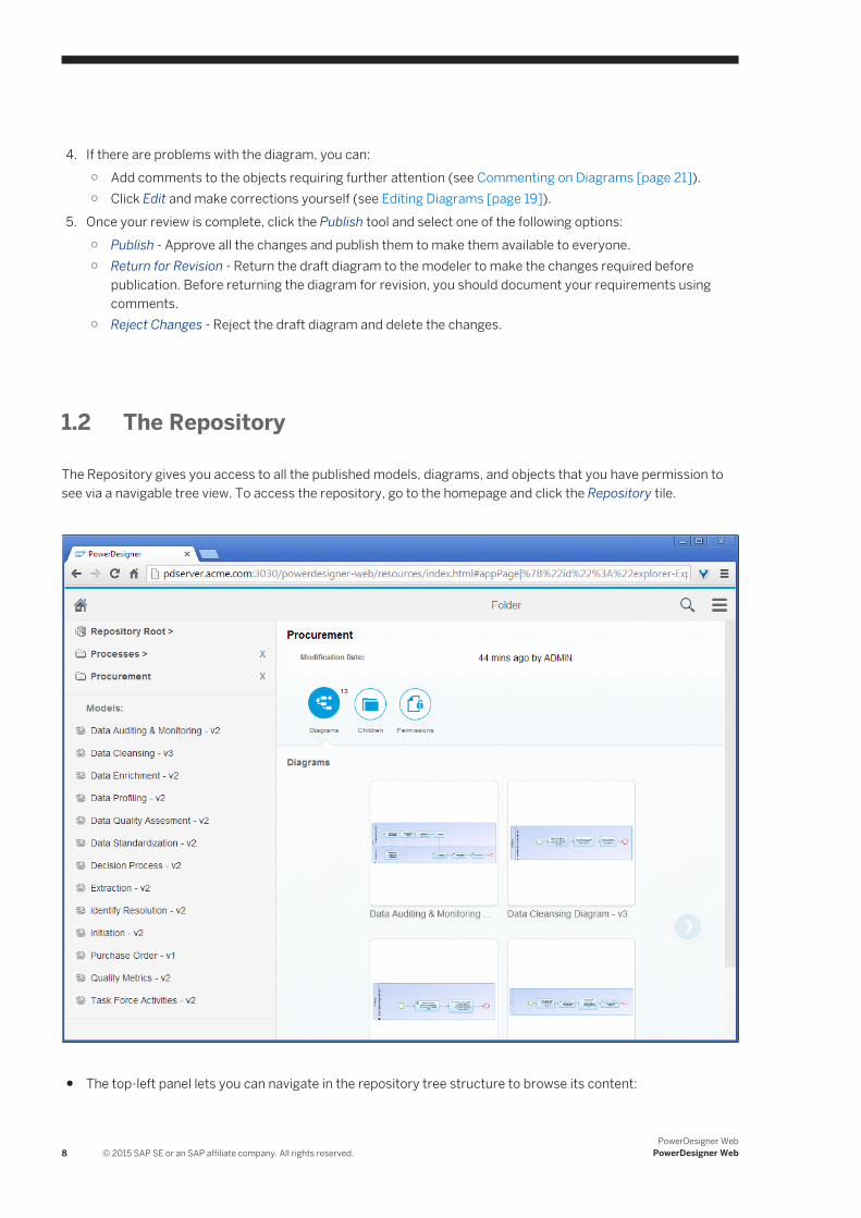
The Repository gives you access to all the published models, diagrams, and objects that you have permission to see via a navigable tree view. To access the repository, go to the homepage and click the Repository tile.
● The top-left panel lets you can navigate in the repository tree structure to browse its content:
8 © 2015 SAP SE or an SAP affiliate company. All rights reserved.PowerDesigner Web
PowerDesigner Web
○ Click a folder, branch, or project to descend into it and view its contents. The item is added to the path, with an X to its right, and its property sheet is displayed in the right-hand panel.
○ Click the X to the right of an item in the path to return to the level above.● The bottom-left panel lists the models that are the immediate children of the currently selected folder,
branch, or project:○ Click a model in the bottom-left panel to view its property sheet in the right-hand panel.
● The right-hand panel displays the property sheet of the currently selected object:○ Click a diagram thumbnail on the Diagrams facet to open it (see The Diagram Viewer [page 17]).○ Click the + tile on the Diagrams facet (or click the menu button and select Create Diagram) to create a
diagram (see Creating a Diagram [page 10]).
NoteThe new diagram will, by default, inherit the permissions of its parent location (see Granting Access Permissions on Repository Items [page 86]).
○ [models] Click a chart thumbnail on the Charts facet to open it.○ [models] Click the + tile on the Charts facet to create a chart (see Creating a Chart [page 11]).○ [folders, branches, projects] Click the menu button and select Create Folder to create a sub-folder.
NoteThe new folder will, by default, inherit the permissions of its parent location (see Granting Access Permissions on Repository Items [page 86]).
○ [models] Select Menu Generate PDF Report or Generate Word Document - to generate a standard report for the model's diagrams (see Sharing, Exporting, and Reporting on Diagrams [page 23]).
○ Click the other facets to explore the properties of the selected object and navigate to other objects (see Object Properties [page 9]).
1.2.1 Object Properties
You can review the properties of an object in the Properties panel, which is available in the Repository and Diagram viewers.
The following facets organize the properties of the object:
● Info - Contains core information for identifying and defining the object.● Children - Lists objects that belong to the object. For example, a process map process can contain sub-
processes or a physical data model table contains columns and indexes. Click an object name in a list to navigate to the property sheet of that object. You can create child objects on this facet. If the appropriate list is not visible, click the Add objects link.
● Depends On - Lists the objects to which the object is connected and on which it depends. If these objects are modified or deleted, the current object may be modified or deleted. Click an object name in a list to navigate to the property sheet of that object. You can attach a business rule to the object on this facet (see Attaching a Business Rule to a Model Object [page 72]).
● Impacts - [read-only] Lists the objects that depend on the object. If the current object is modified or deleted, these objects may be modified or deleted. Click an object name in a list to navigate to the property sheet of that object.
PowerDesigner WebPowerDesigner Web © 2015 SAP SE or an SAP affiliate company. All rights reserved. 9
● Diagrams - Lists the diagrams contained by or associated with the object. Click a diagram thumbnail to open the diagram, or the + tile to create a diagram (see Creating a Diagram [page 10]).
● Charts - [models] Lists the charts defined on the model. Click a chart thumbnail to open the chart, or click the + tile to create a chart (see Creating a Chart [page 11]).
● Versions - [models] Lists the versions of the model published in the repository, with a separate list per branch where appropriate. To compare two versions of a model in a single branch, select their checkboxes and click the Compare tool (see Comparing Diagram Versions [page 24]).
● Permissions - [folders, models] Lists the users and groups with permissions to view and edit the contents of the folder or the diagrams in the model. Users with Full permission on the object and administrators can modify the permissions (see Granting Access Permissions on Repository Items [page 86]).
NotePowerDesigner Web can display most PowerDesigner object properties, but certain properties (including those that are calculated and not directly entered by the user and collections of sub-objects and associated objects) are not presently supported.
1.2.2 Creating a Diagram
If you have Submit or higher permission on a repository folder, you can create a new diagram in the repository.
Procedure
1. Navigate to the repository location where you want to create the diagram, click the Diagrams facet, and then click the + tile (or click the menu button and select Create Diagram).
NoteYou must have at least Submit permission (see Granting Access Permissions on Repository Items [page 86]) for the location where you want to create the diagram to have these options available. If they are not visible to you, contact your administrator.
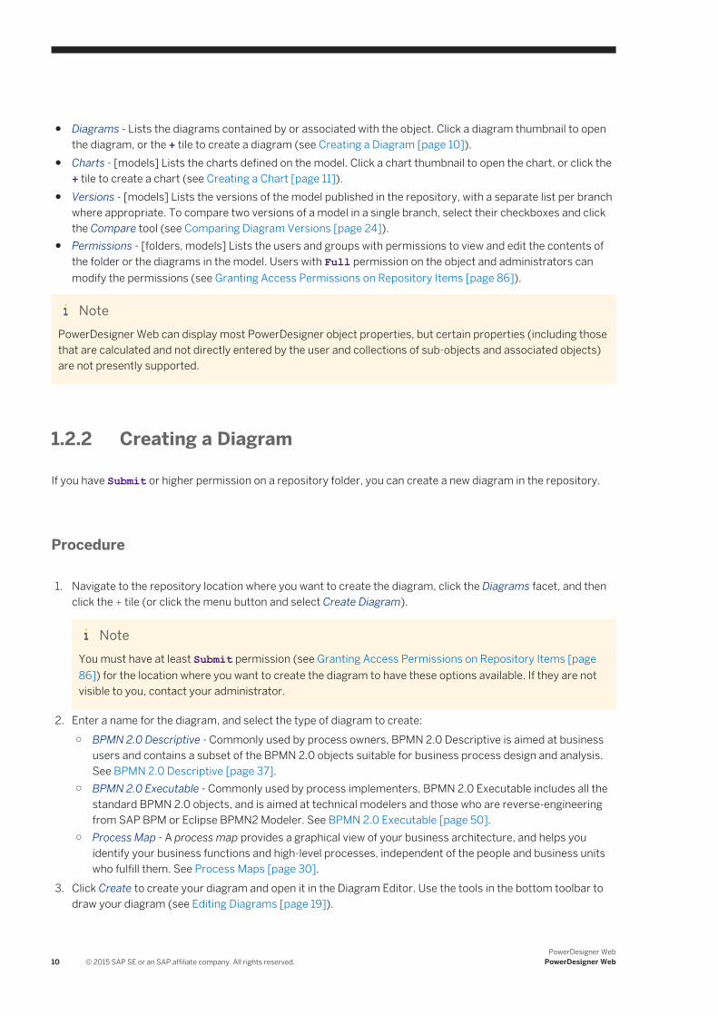
2. Enter a name for the diagram, and select the type of diagram to create:○ BPMN 2.0 Descriptive - Commonly used by process owners, BPMN 2.0 Descriptive is aimed at business
users and contains a subset of the BPMN 2.0 objects suitable for business process design and analysis. See BPMN 2.0 Descriptive [page 37].
○ BPMN 2.0 Executable - Commonly used by process implementers, BPMN 2.0 Executable includes all the standard BPMN 2.0 objects, and is aimed at technical modelers and those who are reverse-engineering from SAP BPM or Eclipse BPMN2 Modeler. See BPMN 2.0 Executable [page 50].
○ Process Map - A process map provides a graphical view of your business architecture, and helps you identify your business functions and high-level processes, independent of the people and business units who fulfill them. See Process Maps [page 30].
3. Click Create to create your diagram and open it in the Diagram Editor. Use the tools in the bottom toolbar to draw your diagram (see Editing Diagrams [page 19]).
10 © 2015 SAP SE or an SAP affiliate company. All rights reserved.PowerDesigner Web
PowerDesigner Web
4. Click Save at any time to save the current state of your diagram. After saving you can navigate away from or close the window. Your draft diagram will not be available to other users, but is accessible to you in the My Draft Diagrams section of your workspace (see The Workspace [page 5]).
5. [optional] Invite other users to comment on your diagram before publication (see Commenting on Diagrams [page 21]).
6. [optional] To verify that the diagram conforms with the appropriate modeling rules, click the Verify button at the bottom right of the window (see Verifying Diagrams [page 25]).
7. When your diagram is complete, click the Publish tool to publish your diagram or to submit it for review before publication (see Publishing Diagrams [page 29]).
1.2.3 Creating a Chart
If you have Submit or higher permission on a model, you can create a chart to analyze its contents. You create charts from the Charts facet of the model's property sheet, and can view them either in that facet or via the Dashboard.
Procedure
1. Navigate to the model for which you want to create a chart, click the Charts facet, and then click the + tile.
NoteYou must have at least Submit permission (see Granting Access Permissions on Repository Items [page 86]) for the model for which you want to create the chart to see the + tile. If it is not visible to you, contact your administrator.
2. Select the appropriate dataset from the list to open it in the Chart Editor.
NoteThe datasets in this list are created using the PowerDesigner desktop client. If you require a dataset that is not available, contact your administrator. For detailed information about working with datasets, see Customizing and Extending PowerDesigner > Extension Files > Chart Datasets (Profile).
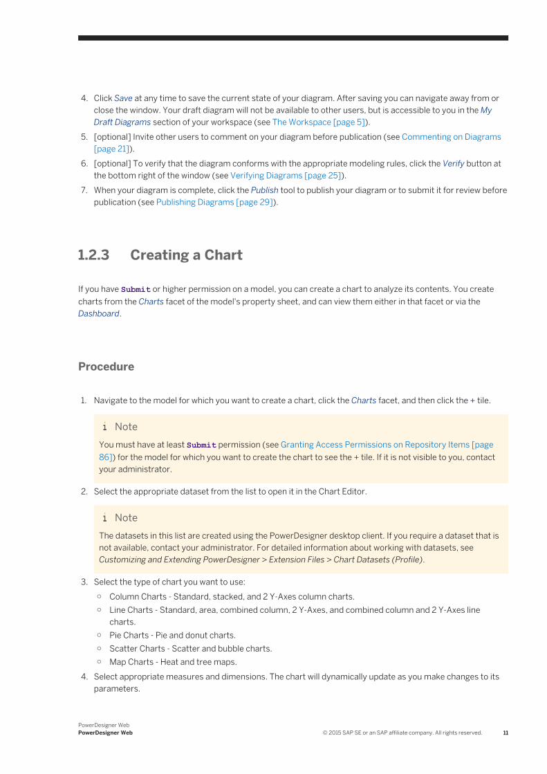
3. Select the type of chart you want to use:○ Column Charts - Standard, stacked, and 2 Y-Axes column charts.○ Line Charts - Standard, area, combined column, 2 Y-Axes, and combined column and 2 Y-Axes line
charts.○ Pie Charts - Pie and donut charts.○ Scatter Charts - Scatter and bubble charts.○ Map Charts - Heat and tree maps.
4. Select appropriate measures and dimensions. The chart will dynamically update as you make changes to its parameters.
PowerDesigner WebPowerDesigner Web © 2015 SAP SE or an SAP affiliate company. All rights reserved. 11
NoteFor examples of measures and dimensions, see Chart Examples [page 14]).
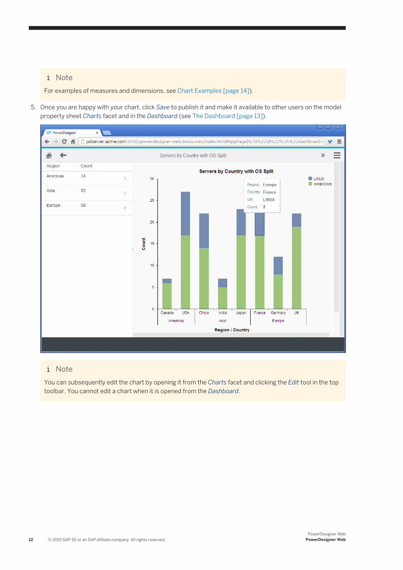
5. Once you are happy with your chart, click Save to publish it and make it available to other users on the model property sheet Charts facet and in the Dashboard (see The Dashboard [page 13]).
NoteYou can subsequently edit the chart by opening it from the Charts facet and clicking the Edit tool in the top toolbar. You cannot edit a chart when it is opened from the Dashboard.
12 © 2015 SAP SE or an SAP affiliate company. All rights reserved.PowerDesigner Web
PowerDesigner Web
1.3 The Dashboard
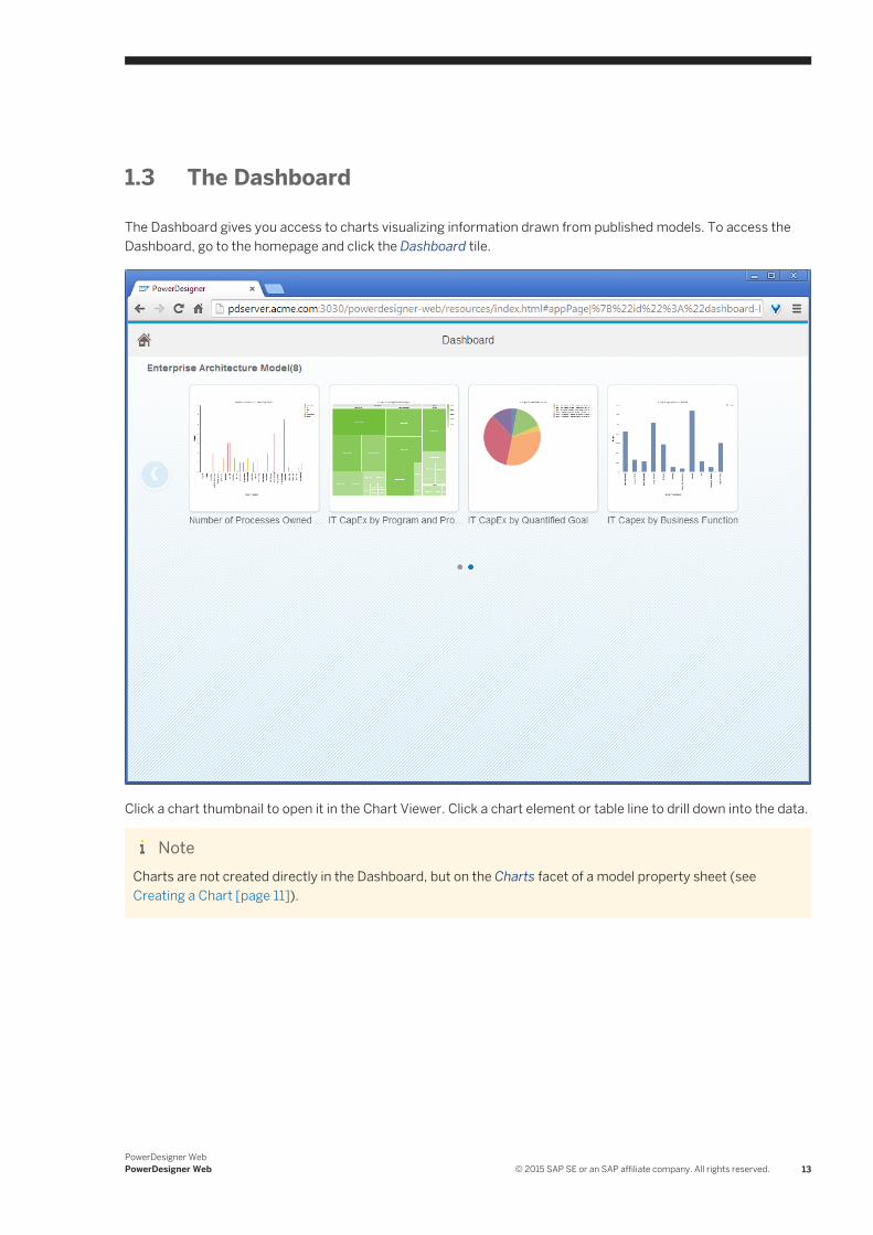
The Dashboard gives you access to charts visualizing information drawn from published models. To access the Dashboard, go to the homepage and click the Dashboard tile.
Click a chart thumbnail to open it in the Chart Viewer. Click a chart element or table line to drill down into the data.
NoteCharts are not created directly in the Dashboard, but on the Charts facet of a model property sheet (see Creating a Chart [page 11]).
PowerDesigner WebPowerDesigner Web © 2015 SAP SE or an SAP affiliate company. All rights reserved. 13
1.3.1 Chart Examples
Example models and an extension file containing datasets to derive charts from them are provided with PowerDesigner.
The following example charts are defined in the EA Charts extension file, which is loaded by default in your repository library (and which is also delivered as part of the EA Example files available at <install_dir>/Examples/EAExample).
Table 1:
Dataset and Chart Configuration Chart
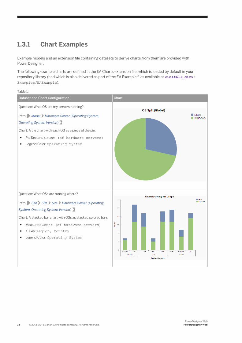
Question: What OS are my servers running?
Path: Model Hardware Server (Operating System,
Operating System Version)
Chart: A pie chart with each OS as a piece of the pie:
● Pie Sectors: Count (of hardware servers)● Legend Color: Operating System
Question: What OSs are running where?
Path: Site Site Site Hardware Server (Operating
System, Operating System Version)
Chart: A stacked bar chart with OSs as stacked colored bars
● Measures: Count (of hardware servers)● X Axis: Region, Country● Legend Color: Operating System
14 © 2015 SAP SE or an SAP affiliate company. All rights reserved.PowerDesigner Web
PowerDesigner Web
Dataset and Chart Configuration Chart
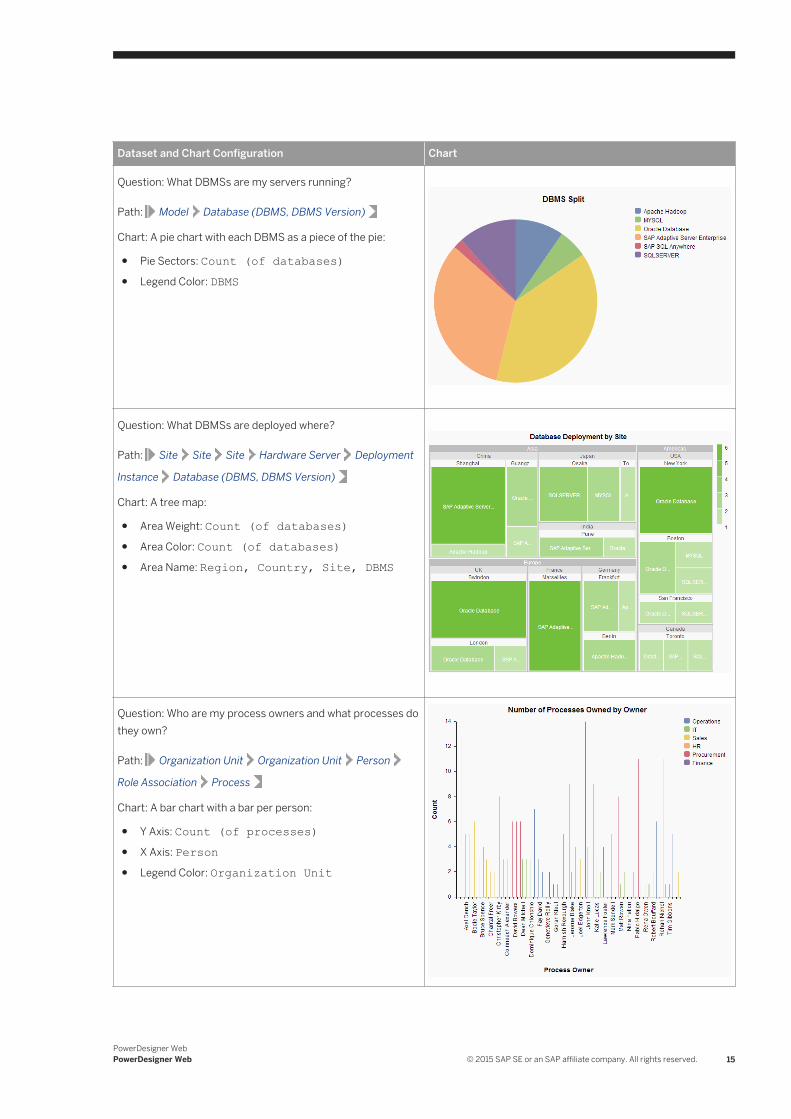
Question: What DBMSs are my servers running?
Path: Model Database (DBMS, DBMS Version)
Chart: A pie chart with each DBMS as a piece of the pie:
● Pie Sectors: Count (of databases)● Legend Color: DBMS
Question: What DBMSs are deployed where?
Path: Site Site Site Hardware Server Deployment
Instance Database (DBMS, DBMS Version)
Chart: A tree map:
● Area Weight: Count (of databases)● Area Color: Count (of databases)● Area Name: Region, Country, Site, DBMS
Question: Who are my process owners and what processes do they own?
Path: Organization Unit Organization Unit Person
Role Association Process
Chart: A bar chart with a bar per person:
● Y Axis: Count (of processes)● X Axis: Person● Legend Color: Organization Unit
PowerDesigner WebPowerDesigner Web © 2015 SAP SE or an SAP affiliate company. All rights reserved. 15
Dataset and Chart Configuration Chart
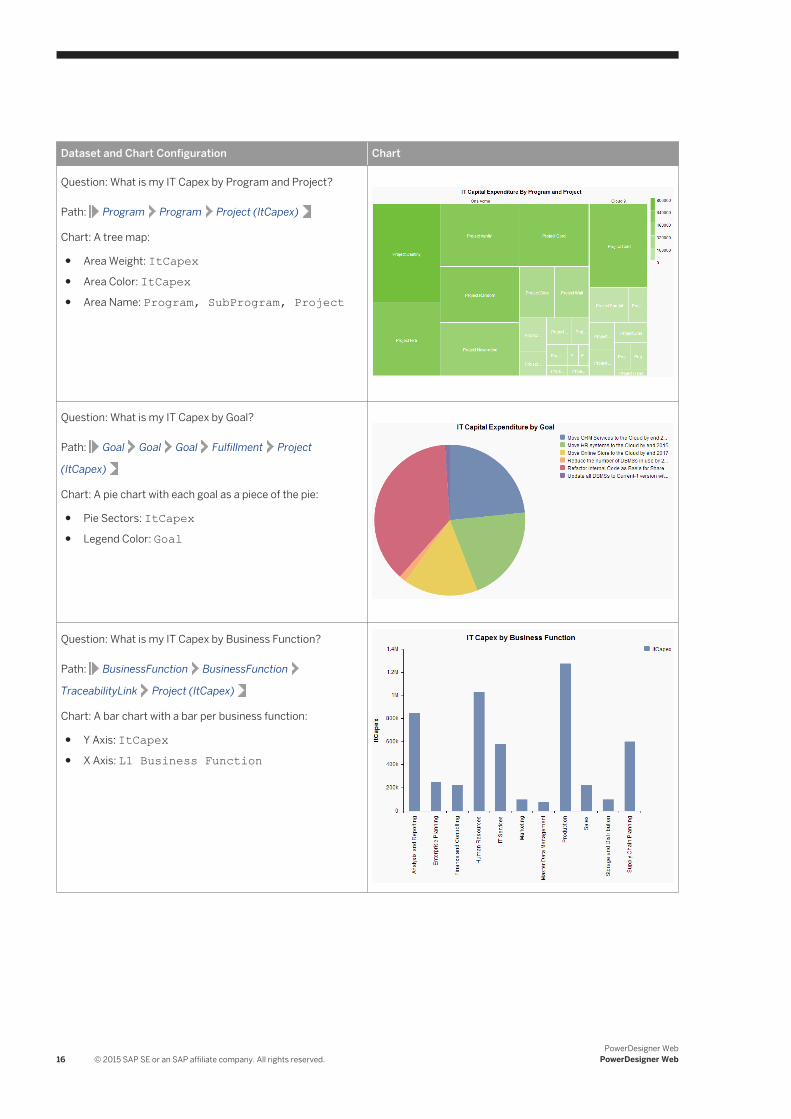
Question: What is my IT Capex by Program and Project?
Path: Program Program Project (ItCapex)
Chart: A tree map:
● Area Weight: ItCapex● Area Color: ItCapex● Area Name: Program, SubProgram, Project
Question: What is my IT Capex by Goal?
Path: Goal Goal Goal Fulfillment Project
(ItCapex)
Chart: A pie chart with each goal as a piece of the pie:
● Pie Sectors: ItCapex● Legend Color: Goal
Question: What is my IT Capex by Business Function?
Path: BusinessFunction BusinessFunction
TraceabilityLink Project (ItCapex)
Chart: A bar chart with a bar per business function:
● Y Axis: ItCapex● X Axis: L1 Business Function
16 © 2015 SAP SE or an SAP affiliate company. All rights reserved.PowerDesigner Web
PowerDesigner Web
Dataset and Chart Configuration Chart
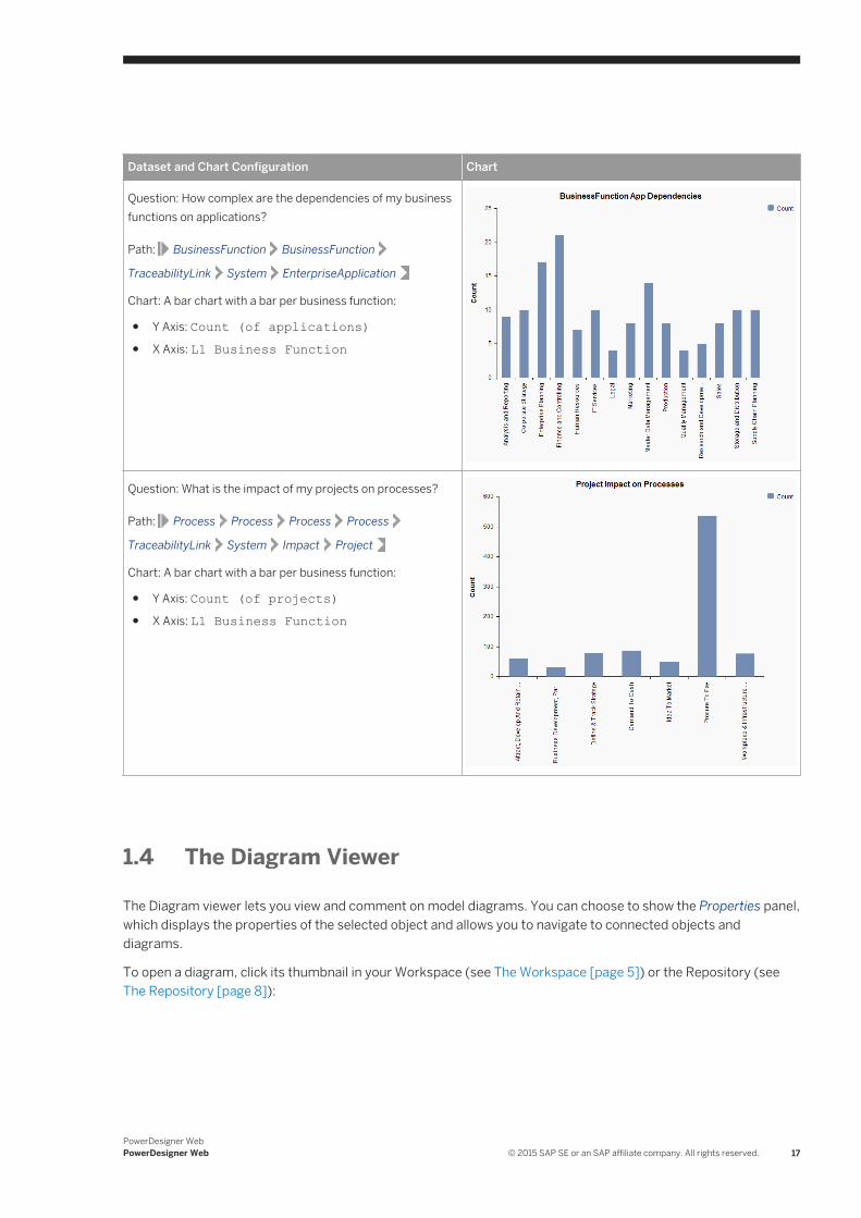
Question: How complex are the dependencies of my business functions on applications?
Path: BusinessFunction BusinessFunction
TraceabilityLink System EnterpriseApplication
Chart: A bar chart with a bar per business function:
● Y Axis: Count (of applications)● X Axis: L1 Business Function
Question: What is the impact of my projects on processes?
Path: Process Process Process Process
TraceabilityLink System Impact Project
Chart: A bar chart with a bar per business function:
● Y Axis: Count (of projects)● X Axis: L1 Business Function
1.4 The Diagram Viewer
The Diagram viewer lets you view and comment on model diagrams. You can choose to show the Properties panel, which displays the properties of the selected object and allows you to navigate to connected objects and diagrams.
To open a diagram, click its thumbnail in your Workspace (see The Workspace [page 5]) or the Repository (see The Repository [page 8]):
PowerDesigner WebPowerDesigner Web © 2015 SAP SE or an SAP affiliate company. All rights reserved. 17

● In the top toolbar:○ [BPMN 2.0 diagrams and process maps] Click the Edit tool to begin editing the diagram (see Editing
Diagrams [page 19]).○ Click the Show Comments tool to open the Comments panel and review or add comments (see
Commenting on Diagrams [page 21]). Select an object in the diagram to show only the comments attached to it, or click the diagram background to show all the comments.
○ At the border between the diagram and properties panels:○ Click the Hide Diagram tool to hide the diagram and maximize the Properties panel. Click the Show
Diagram tool to redisplay the diagram.○ Click the Hide Properties tool to hide the Properties panel and maximize the Diagram panel. Click the
Show Properties tool to redisplay the Properties panel.
○ Select Menu Print Diagram to generate a printable image of the diagram.
○ Select Menu Share Link to obtain a shareable link to the diagram or object.
○ Select Menu Export Diagram Image to save the diagram to an SVG file.
○ Select Menu Generate PDF Report or Generate Word Document - to generate a standard report from the diagram (see Sharing, Exporting, and Reporting on Diagrams [page 23]).
○ [BPMN] Select Menu Export BPMN2 File to export your diagram to a standard BPMN 2.0 or SAP BPM file.
● In the diagram panel:
18 © 2015 SAP SE or an SAP affiliate company. All rights reserved.PowerDesigner Web
PowerDesigner Web
○ Click and drag to move around the diagram. Use your mouse wheel to zoom in and out.○ Select an object or link to display its properties in the Properties panel at right (see Object Properties
[page 9]).
1.4.1 Editing Diagrams
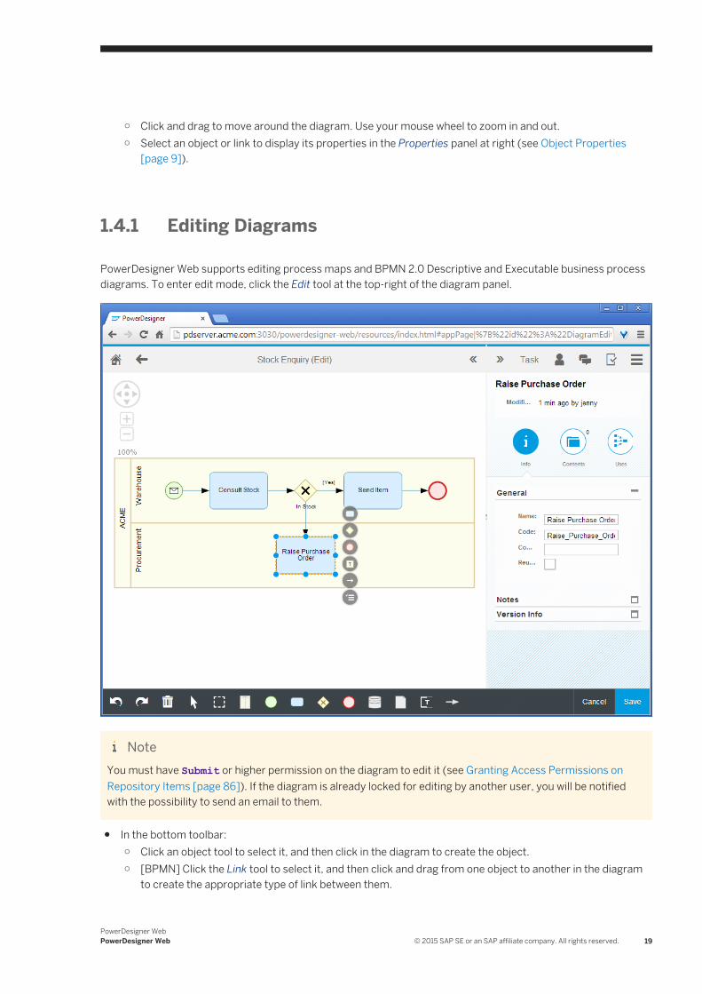
PowerDesigner Web supports editing process maps and BPMN 2.0 Descriptive and Executable business process diagrams. To enter edit mode, click the Edit tool at the top-right of the diagram panel.
NoteYou must have Submit or higher permission on the diagram to edit it (see Granting Access Permissions on Repository Items [page 86]). If the diagram is already locked for editing by another user, you will be notified with the possibility to send an email to them.
● In the bottom toolbar:○ Click an object tool to select it, and then click in the diagram to create the object.○ [BPMN] Click the Link tool to select it, and then click and drag from one object to another in the diagram
to create the appropriate type of link between them.
PowerDesigner WebPowerDesigner Web © 2015 SAP SE or an SAP affiliate company. All rights reserved. 19
○ Click the Undo (CTRL+Z) or Redo (CTRL+Y) tool to step back or forward through your changes since the last save.
○ Select an object and then click the Delete tool or press Delete (or, in Safari, press FN+Delete) to delete it.○ Select multiple objects by clicking them while holding down the shift key or by clicking the Lasso tool and
then clicking and dragging over them.○ Click Save to save your changes from this editing session or click Cancel to cancel your changes and
revert to your last saved version. Your latest saved version is available in your Workspace (The Workspace [page 5]) and can be reopened at any time.
● In the Diagram panel:○ Click and drag to move around the diagram. Use your mouse wheel to zoom in and out.○ Select an object or link to display its properties in the Properties panel at right (see Object Properties
[page 9]).○ Select an object to display its context toolbar:
○ Click and release an object tool to create a new object immediately next to it or (for BPMN) below it.○ Click and drag an object tool to control the placement of the new object.○ [BPMN] Click and drag the Link tool to create a link from the present object to another object.○ [BPMN] Click the Properties tool to change the object type.
● In the top toolbar:○ Click the Show Comments tool to open the Comments panel and review or add comments (see
Commenting on Diagrams [page 21]). Select an object in the diagram to show only the comments attached to it, or click the diagram background to show all the comments.
○ Click the Invite to Comment tool to invite other users to view your draft diagram and post comments on the objects in it before you submit it for publication.
○ At the border between the diagram and properties panels:○ Click the Hide Diagram tool to hide the diagram and maximize the Properties panel. Click the Show
Diagram tool to redisplay the diagram.○ Click the Hide Properties tool to hide the Properties panel and maximize the Diagram panel. Click the
Show Properties tool to redisplay the Properties panel.
○ [BPMN] Select Menu Change Pool to Horizontal/Vertical to change the orientation of your pools and lanes to horizontal (left to right) or vertical (top-to-bottom).
NoteYou can only change the orientation of your diagram if the diagram does not contain any pools.
○ Select Menu Compare Versions to compare your version of the diagram with the published version from which you began (see Comparing Diagram Versions [page 24]).
○ Select Menu Print Diagram to generate a printable image of the diagram.
○ Select Menu Share Link to obtain a shareable link to the diagram or object.
○ Select Menu Export Diagram Image to save the diagram to an SVG file.
○ Select Menu Generate PDF Report or Generate Word Document - to generate a standard report from the diagram (see Sharing, Exporting, and Reporting on Diagrams [page 23]).
○ [BPMN] Select Menu Import BPMN2 File to import a standard BPMN 2.0 or SAP BPM file into your diagram.
○ [BPMN] Select Menu Export BPMN2 File to export your diagram to a standard BPMN 2.0 or SAP BPM file.
20 © 2015 SAP SE or an SAP affiliate company. All rights reserved.PowerDesigner Web
PowerDesigner Web
○ When you have completed your changes, click the Publish tool and then select:○ Submit Changes - to submit your diagram for review by accredited users before publication. You will
no longer be able to edit it.○ Publish - to make your changes available to all users via the repository (requires Write or higher
permission).○ Revert Changes - to delete your draft diagram and abandon your changes. The published version of
the diagram will remain unchanged.
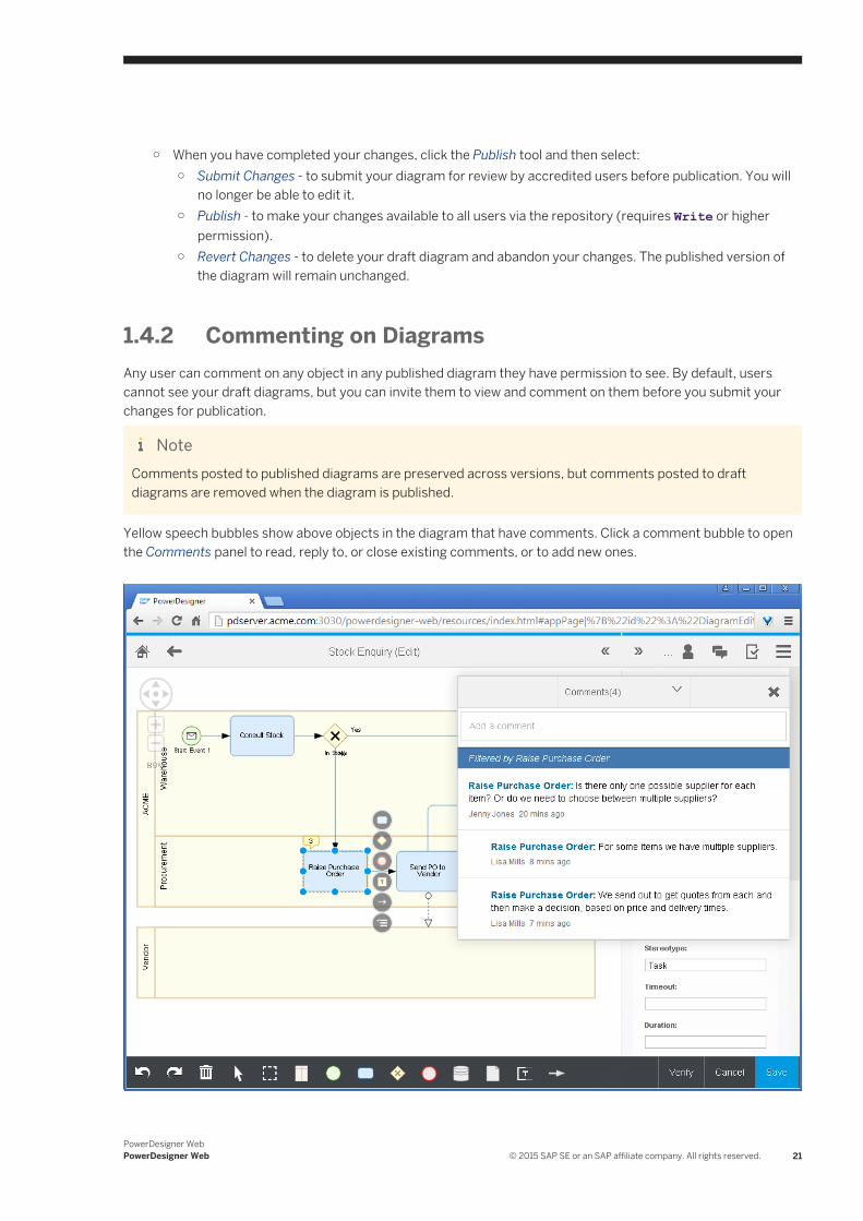
1.4.2 Commenting on DiagramsAny user can comment on any object in any published diagram they have permission to see. By default, users cannot see your draft diagrams, but you can invite them to view and comment on them before you submit your changes for publication.
NoteComments posted to published diagrams are preserved across versions, but comments posted to draft diagrams are removed when the diagram is published.
Yellow speech bubbles show above objects in the diagram that have comments. Click a comment bubble to open the Comments panel to read, reply to, or close existing comments, or to add new ones.
PowerDesigner WebPowerDesigner Web © 2015 SAP SE or an SAP affiliate company. All rights reserved. 21
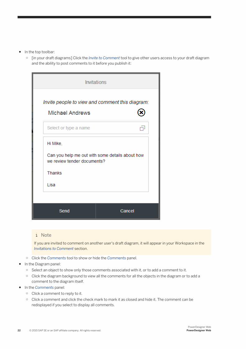
● In the top toolbar:○ [in your draft diagrams] Click the Invite to Comment tool to give other users access to your draft diagram
and the ability to post comments to it before you publish it:
NoteIf you are invited to comment on another user's draft diagram, it will appear in your Workspace in the Invitations to Comment section.
○ Click the Comments tool to show or hide the Comments panel.● In the Diagram panel:
○ Select an object to show only those comments associated with it, or to add a comment to it.○ Click the diagram background to view all the comments for all the objects in the diagram or to add a
comment to the diagram itself.● In the Comments panel:
○ Click a comment to reply to it.○ Click a comment and click the check mark to mark it as closed and hide it. The comment can be
redisplayed if you select to display all comments.
22 © 2015 SAP SE or an SAP affiliate company. All rights reserved.PowerDesigner Web
PowerDesigner Web
○ Click a comment that you have posted (which does not have any replies) and click the pencil to edit it or the trash can to delete it.
○ Click an object name in a comment to center the diagram on that object.○ Click the top of the panel to toggle between showing all comments and hiding comments that are marked
as closed.
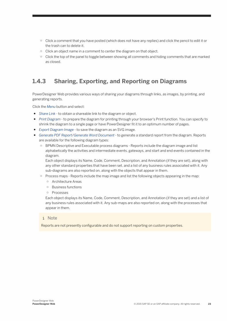
1.4.3 Sharing, Exporting, and Reporting on Diagrams
PowerDesigner Web provides various ways of sharing your diagrams through links, as images, by printing, and generating reports.
Click the Menu button and select:
● Share Link - to obtain a shareable link to the diagram or object.● Print Diagram - to prepare the diagram for printing through your browser's Print function. You can specify to
shrink the diagram to a single page or have PowerDesigner fit it to an optimum number of pages.● Export Diagram Image - to save the diagram as an SVG image.● Generate PDF Report/Generate Word Document - to generate a standard report from the diagram. Reports
are available for the following diagram types:○ BPMN Descriptive and Executable process diagrams - Reports include the diagram image and list
alphabetically the activities and intermediate events, gateways, and start and end events contained in the diagram.Each object displays its Name, Code, Comment, Description, and Annotation (if they are set), along with any other standard properties that have been set, and a list of any business rules associated with it. Any sub-diagrams are also reported on, along with the objects that appear in them.
○ Process maps - Reports include the map image and list the following objects appearing in the map:○ Architecture Areas○ Business functions○ Processes
Each object displays its Name, Code, Comment, Description, and Annotation (if they are set) and a list of any business rules associated with it. Any sub-maps are also reported on, along with the processes that appear in them.
NoteReports are not presently configurable and do not support reporting on custom properties.
PowerDesigner WebPowerDesigner Web © 2015 SAP SE or an SAP affiliate company. All rights reserved. 23
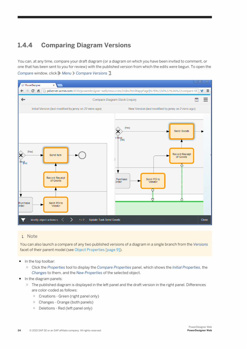
1.4.4 Comparing Diagram Versions
You can, at any time, compare your draft diagram (or a diagram on which you have been invited to comment, or one that has been sent to you for review) with the published version from which the edits were begun. To open the Compare window, click Menu Compare Versions .
NoteYou can also launch a compare of any two published versions of a diagram in a single branch from the Versions facet of their parent model (see Object Properties [page 9]).
● In the top toolbar:○ Click the Properties tool to display the Compare Properties panel, which shows the Initial Properties, the
Changes to them, and the New Properties of the selected object.● In the diagram panels:
○ The published diagram is displayed in the left panel and the draft version in the right panel. Differences are color-coded as follows:○ Creations - Green (right panel only)○ Changes - Orange (both panels)○ Deletions - Red (left panel only)
24 © 2015 SAP SE or an SAP affiliate company. All rights reserved.PowerDesigner Web
PowerDesigner Web
○ Click an object in either panel to select it in the list of changes.○ Click and drag to move around the diagram. Use your mouse wheel to zoom in and out.○ Review or add comments in the right panel (see Commenting on Diagrams [page 21]).
● In the bottom toolbar:○ Click the filter tool to control the display of creations, changes, symbol changes (including creation and
deletion of symbols), and deletions.○ Click the left or right arrows to go to the next or previous change.○ Click the change text itself to display the list of changes.○ Click Close to return to the Diagram Viewer.
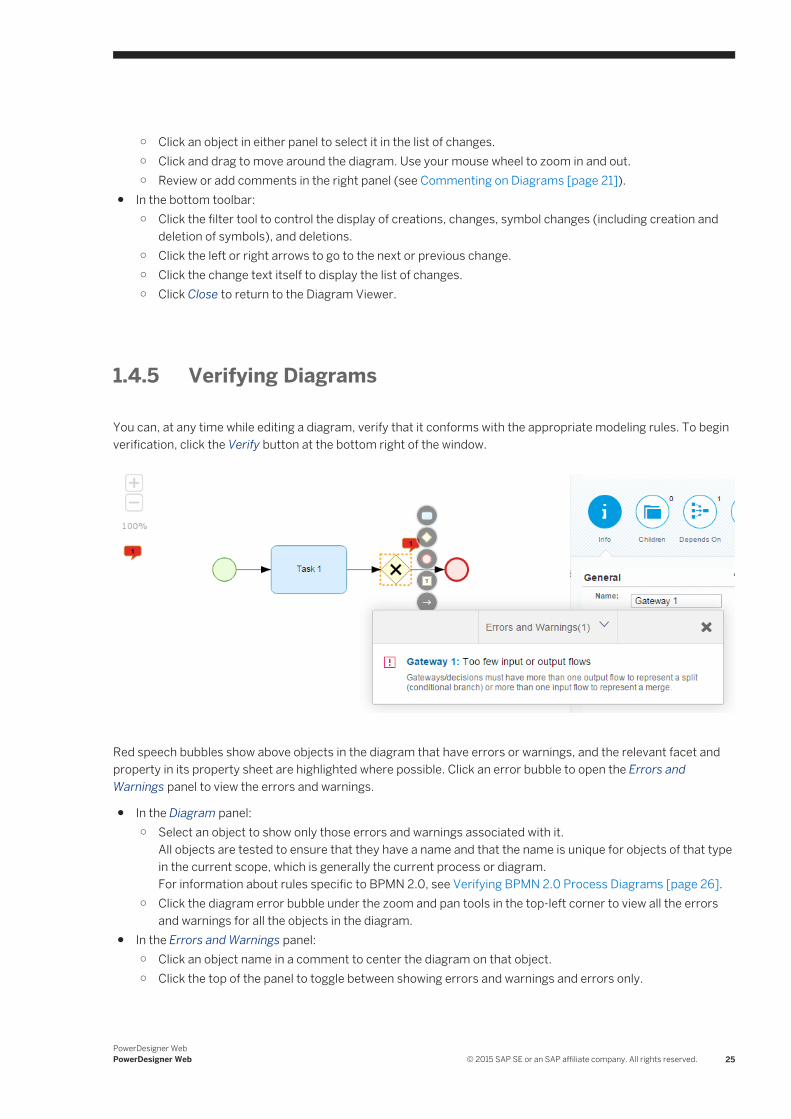
1.4.5 Verifying Diagrams
You can, at any time while editing a diagram, verify that it conforms with the appropriate modeling rules. To begin verification, click the Verify button at the bottom right of the window.
Red speech bubbles show above objects in the diagram that have errors or warnings, and the relevant facet and property in its property sheet are highlighted where possible. Click an error bubble to open the Errors and Warnings panel to view the errors and warnings.
● In the Diagram panel:○ Select an object to show only those errors and warnings associated with it.
All objects are tested to ensure that they have a name and that the name is unique for objects of that type in the current scope, which is generally the current process or diagram.For information about rules specific to BPMN 2.0, see Verifying BPMN 2.0 Process Diagrams [page 26].
○ Click the diagram error bubble under the zoom and pan tools in the top-left corner to view all the errors and warnings for all the objects in the diagram.
● In the Errors and Warnings panel:○ Click an object name in a comment to center the diagram on that object.○ Click the top of the panel to toggle between showing errors and warnings and errors only.
PowerDesigner WebPowerDesigner Web © 2015 SAP SE or an SAP affiliate company. All rights reserved. 25
Once you have launched a diagram verification, PowerDesigner Web continues to verify your changes in real time so that as you correct issues, the counts of errors and warnings in the bubble and list decrease. To exit validation mode, click Save to save your changes, and then press F5 to refresh your browser window.
1.4.5.1 Verifying BPMN 2.0 Process Diagrams
PowerDesigner Web provides a set of standard verification rules for BPMN 2 process diagrams.
The verification rules in this list apply to BPMN 2.0 Executable and (where appropriate) BPMN 2.0 Descriptive:
● Activities:○ Missing incoming flow/Missing outgoing flow: Activities/processes must have at least one
incoming and one outgoing flow.○ Invalid implementation: Activities/processes cannot be implemented by an activity/process that is,
itself, implemented.○ Invalid decomposition: Tasks must not contain other objects. Only sub-processes and other
composite activities can contain other objects.○ Invalid item-aware elements: Events and tasks must only contain item-aware objects of type Data
Input or Data Output.○ Too many default flows: Activities and intermediate events must not have more than one default
outgoing flow.○ Invalid implementation type: Call activities must have an implementation type of Reuse
process.○ Missing start/Missing end: Sub-processes/composite processes must have at least one start and
at least one end.○ Invalid incoming flows/Invalid outgoing flows: Event sub-processes must not have any
incoming or outgoing flows.○ Too many start events: Event sub-processes must have exactly one start event.○ Invalid incoming flows/Invalid outgoing flows: Compensation activities must not have any
incoming sequence flows that are not of type Compensation, nor any outgoing sequence flows.○ Invalid for export: Manual tasks cannot be exported to a NetWeaver BPMN2 file.
● Gateways:○ Too few incoming or outgoing flows: Gateways/decisions must have more than one outgoing
flow to represent a split (conditional branch) or more than one incoming flow to represent a merge.○ Too many default flows: Gateways must not have more than one default outgoing flow.
● Sequence and Message Flows:○ Missing source/Missing destination: Flows must have both a source and a destination object.○ Invalid message format: Sequence flows must not have message formats attached to them.○ Undefined message format: Message flows must either specify a message format or have their
message format set to <None>.○ Duplicate definition: Message formats must not have the same definition as another message
format.○ Invalid correlation property: Message flows must specify a correlation property from among
those defined in their correlation key.
26 © 2015 SAP SE or an SAP affiliate company. All rights reserved.PowerDesigner Web
PowerDesigner Web
○ Invalid source/Invalid destination: Message flows can only go from (have as sources) and point to (have as destinations) activities, pools, catching message intermediate events, or message start events.
● Events:○ Missing outgoing flow: Starts must have at least one outgoing flow.○ Missing incoming flow: Ends must have at least one incoming flow.○ Not permitted at top level: Start events of type Escalation, Error, or Compensation are only
permitted in event sub-processes.○ Not permitted in sub-process: Start events that are not of type Standard are not permitted in sub-
processes.○ Not permitted in event sub-process: Start events of type Standard are not permitted in event
sub-processes.○ Not permitted in transaction: Start events that are not of type Standard are not permitted in
transactions.○ Not permitted in ad-hoc sub-process: Start and end events are not permitted in ad-hoc sub-
processes.○ Only permitted in transactions: End events of type Cancel are not permitted at the top level or in
event sub-processes. They are only permitted in transactions.○ Invalid item-aware elements: Events and tasks must only contain item-aware objects of type Data
Input or Data Output.○ Too many default flows: Activities and intermediate events must not have more than one default
outgoing flow.○ Too few event definitions: Multiple events must contain at least two event definitions.○ Invalid event definitions: Multiple and parallel multiple events of type:
○ Start (at the top level) - can only contain Message, Timer, Conditional, Error, and Signal event definitions.
○ Interrupting start (in an event sub-process) - can only contain Message, Timer, Escalation, Conditional, Error, Compensation, and Signal event definitions.
○ Non-interrupting start (in an event sub-process) - can only contain Message, Timer, Escalation, Conditional, and Signal event definitions.
○ Interrupting boundary - can only contain Message, Timer, Escalation, Conditional, Error, Cancel, Compensation, and Signal event definitions.
○ Non-interrupting boundary - can only contain Message, Timer, Escalation, Conditional, and Signal event definitions.
○ Intermediate catching - can only contain Message, Timer, Conditional, Link, and Signal event definitions.
○ Intermediate throwing - can only contain Message, Escalation, Link, Compensation, and Signal event definitions.
○ End - can only contain Message, Error, Escalation, Cancel, Compensation, Signal, and Terminate event definitions.
○ Invalid decomposition: Events must not be decomposed. They must not contain other objects.○ Missing stereotype: Events must bear a stereotype to define what type of event it is.○ Invalid reusability: Events must not be specified as reusable.
● Data and Data Associations:○ Unused resource: Data objects/resources must be linked to at least one activity/process.
PowerDesigner WebPowerDesigner Web © 2015 SAP SE or an SAP affiliate company. All rights reserved. 27
○ Not permitted in tasks or events: Data objects and data object references are not permitted in tasks or events.
○ Missing data object/Invalid data object: Data object references must specify the data object to which they are a reference.
○ Invalid source/Invalid destination: Data associations/resource flows can only go from (have as sources) and point to (have as destinations) activities/processes and data objects/resources.
○ Missing source item/Invalid source item : Data associations with a transformation type of Output must specify an item-aware element (of type Data Output) from among those defined on their source activity, which will be transferred from the activity to the data.
○ Missing target item/Invalid target item: Data associations with a transformation type of Input must specify an item-aware element (of type Data Input) from among those defined on their target activity, which will be transferred to the activity from the data.
● Item-aware Elements:○ Not permitted in start events: Item-aware elements of type Data Input are not permitted in start
events.○ Not permitted in intermediate catch events: Item-aware elements of type Data Input are not
permitted in intermediate catch events.○ Not permitted in intermediate throw events: Item-aware elements of type Data Output are not
permitted in intermediate throw events.○ Not permitted in end events: Item-aware elements of type Data Output are not permitted in end
events.● Correlation Keys:
○ Missing variables: Correlation keys must contain at least one variable.● Implementation Objects - These objects are not commonly modeled in PowerDesigner Web but may be
present in models created in the PowerDesigner desktop client:○ Missing interfaces: Service providers must contain at least one interface.○ Missing operations: Interfaces must contain at least one operation.○ Missing input message (One-Way): One-way operations must specify an input message.○ Missing input message (Request-Response): Request-response operations must specify both an
input and an output message.○ Missing input message (Solicit Response): Solicit response operations must specify both an
input and an output message.○ Missing output message (Notification): Notification operations must specify an output
message.○ Missing output message (Request-Response): Request-response operations must specify both
an input and an output message.○ Missing output message (Solicit Response): Solicit response operations must specify both an
input and an output message.
28 © 2015 SAP SE or an SAP affiliate company. All rights reserved.PowerDesigner Web
PowerDesigner Web
1.4.6 Publishing Diagrams
When your changes (or the changes you are reviewing) are complete, you can publish them and make the new version of the diagram available to all users.
Context
NoteYou must have Write permission or higher to directly publish a diagram. If you have only the Submit permission, your changes must be reviewed before publication. In this case, select Publish Submit Changes .
Procedure
1. [recommended] Review the content of the diagram for accuracy and compliance with your organization's modeling standards:○ To verify that it conforms with the appropriate modeling rules, click the Verify button at the bottom right
of the window (see Verifying Diagrams [page 25]).
○ To obtain an interactive analysis of the changes made from the published version, select MenuCompare Versions (see Comparing Diagram Versions [page 24]).
2. Click the Publish tool and select Publish.3. Enter a comment to explain the purpose of these changes.
The publication comment is displayed against the version number on the model property sheet Versions tab (see Object Properties [page 9]).
4. Click OK to publish the changes.A new version of the diagram is published and you return to your workspace. The published diagram is available at the head of the Recently Viewed Diagrams list.
1.4.7 Creating Reusable Objects in the Library
You can create objects for reuse in your models by saving them in a diagram in the repository Library folder. Objects saved in this way can be reused by other users in their diagrams.
There are two ways to reuse objects:
● When creating an object in a diagram and entering its name on its symbol or property sheet, the names of objects saved in the library (along with those in the local diagram) are proposed to you. Select a name from the list to reuse the existing object.
PowerDesigner WebPowerDesigner Web © 2015 SAP SE or an SAP affiliate company. All rights reserved. 29
NoteYour local object is replaced by a shortcut to the library object, which is read-only, and any properties you had previously defined for the object are lost.
● Certain object properties require you to select an object as their value. Click the Select Object button to the right of the property field to open a list containing all the objects of this type in the library (along with those in the local diagram). Select an object to assign it to the property.
The following BPMN 2.0 Descriptive and Executable objects can be reused:
● Pools● Lanes● Tasks/Activities● Data Objects/Data Stores● Intermediate Events
The following BPMN 2.0 Descriptive and Executable objects cannot be reused:
● Start/End Events● Gateways● Sequence and Message Links and Data Associations
NoteBPMN 2.0 Descriptive objects cannot be reused in BPMN 2.0 Executable diagrams and vice versa.
1.5 Process Maps
A process map provides a graphical view of your business architecture, and helps you identify your business functions and high-level processes, independent of the people and business units who fulfill them.
The following example shows a top-level process map in which the groupings Management,Core, and Support are defined in architecture areas, and ten high-level processes are defined:
30 © 2015 SAP SE or an SAP affiliate company. All rights reserved.PowerDesigner Web
PowerDesigner Web
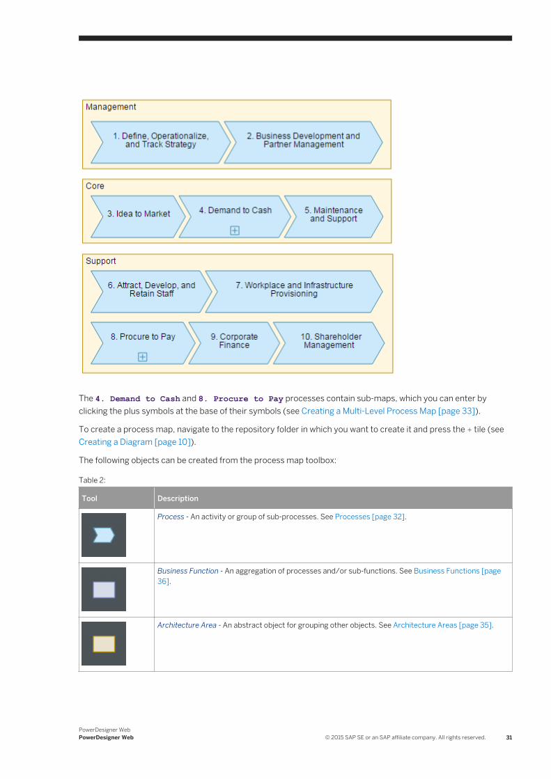
The 4. Demand to Cash and 8. Procure to Pay processes contain sub-maps, which you can enter by clicking the plus symbols at the base of their symbols (see Creating a Multi-Level Process Map [page 33]).
To create a process map, navigate to the repository folder in which you want to create it and press the + tile (see Creating a Diagram [page 10]).
The following objects can be created from the process map toolbox:
Table 2:
Tool Description
Process - An activity or group of sub-processes. See Processes [page 32].
Business Function - An aggregation of processes and/or sub-functions. See Business Functions [page 36].
Architecture Area - An abstract object for grouping other objects. See Architecture Areas [page 35].
PowerDesigner WebPowerDesigner Web © 2015 SAP SE or an SAP affiliate company. All rights reserved. 31
NotePrograms, projects, and goals created in a process map in the PowerDesigner desktop client can be displayed, but not created or modified in PowerDesigner Web.
1.5.1 Processes
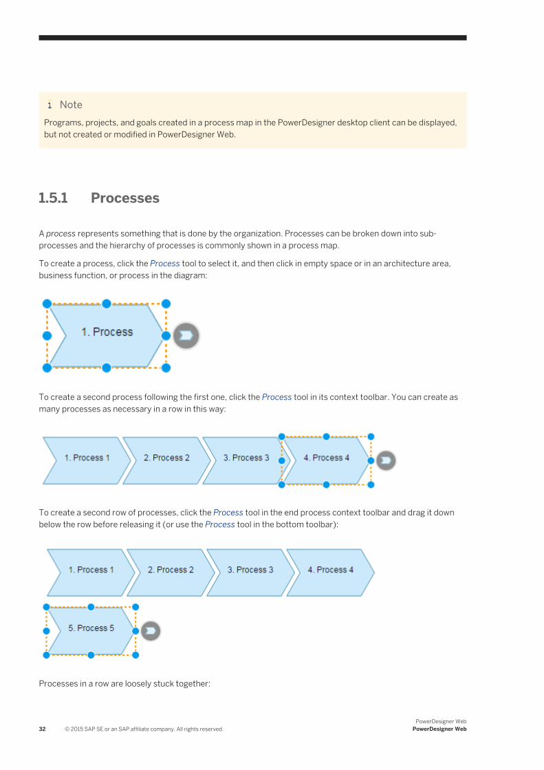
A process represents something that is done by the organization. Processes can be broken down into sub-processes and the hierarchy of processes is commonly shown in a process map.
To create a process, click the Process tool to select it, and then click in empty space or in an architecture area, business function, or process in the diagram:
To create a second process following the first one, click the Process tool in its context toolbar. You can create as many processes as necessary in a row in this way:
To create a second row of processes, click the Process tool in the end process context toolbar and drag it down below the row before releasing it (or use the Process tool in the bottom toolbar):
Processes in a row are loosely stuck together:
32 © 2015 SAP SE or an SAP affiliate company. All rights reserved.PowerDesigner Web
PowerDesigner Web
● To align the start or end of a row of processes with another symbol, drag the first or last process (without going beyond the upper or lower bounds of the row) and drop it when the guide line appears. The other processes in the row move with it.
● To detach a process from its row, drag it beyond the upper or lower bound of its row.● To change the order of a row of processes, drag one process and drop it after the process you want it to
follow. The other processes will make room for it if necessary:
NoteProcesses receive a number when they are created. If you move processes around, the numbers may no longer correspond to the desired order: You can modify the number of a process in the Number ID field of its property sheet, and the other numbers will be updated to avoid duplications and fill holes in the sequence where possible.
● To create a sub-map inside a process, double-click its symbol (see Creating a Multi-Level Process Map [page 33]).
● To link a process to a business process diagram that models its steps, use the Diagrams facet (see Linking Processes to Business Process Diagrams [page 34]).
Processes can have the following properties:
Table 3:
Property Description
Name/Code/Comment
Identify the object. The name should clearly convey the object's purpose to non-technical users, while the code, which is used for generating code or scripts, may be abbreviated, and should not normally include spaces. You can optionally add a comment to provide more detailed information about the object. By default the code is generated from the name by applying the naming conventions specified in the model options. To decouple name-code synchronization, click to release the = button to the right of the Code field.
Stereotype Extends the semantics of the object. You can enter a stereotype directly in this field, or add stereotypes to the list by specifying them in an extension file.
Number ID Specifies the number of the process in the sequence. Numbers are allotted sequentially as processes are created. If you move processes around, the numbers may no longer correspond to the desired order. You can modify the number of a process here, and the other numbers will be changed to avoid duplications and fill holes in the sequence where possible.
Reused process Specifies the name of the reused process.
Sub-processes can appear inside the process symbol or in a sub-map, and are listed in both cases on the Children facet of its property sheet.
1.5.1.1 Creating a Multi-Level Process Map
Process maps are commonly maintained by process analysts who, starting from a top-level overview of business areas and high-level functions, decompose top-level processes into sub-processes. Some or all of the processes in the top-level map are decomposed into sub-processes containing sub-maps and so on down through a number
PowerDesigner WebPowerDesigner Web © 2015 SAP SE or an SAP affiliate company. All rights reserved. 33
of levels. Architecture areas and business functions are only permitted in the top-level and cannot be created in sub-maps.
It is common practice to decompose processes to four levels in a process map, and then to model the steps of each fourth-level process in a business process diagram (see Linking Processes to Business Process Diagrams [page 34]).
To create a sub-map inside a process, double-click its symbol. Processes that you create in this sub-map are sub-processes of the initial process and are listed on the Children facet of its property sheet. Their fully-qualified number includes the number of the parent process as a prefix.
To go down into an existing submap, click the plus sign in the bottom center of the process symbol or zoom into the process symbol until it fills the screen. To go back up to the parent map, click the Back arrow at the top-left of the diagram viewer or zoom out till its scale is less than 20%.
NoteProcess maps and any sub-maps contained in their processes are treated as a single diagram for simplicity during publication and in the Repository browser. To bookmark a particular sub-map for easy access, pin it in the Recently Viewed Diagrams list in your Workspace.
1.5.1.2 Linking Processes to Business Process Diagrams
While you can decompose processes into sub-processes in a process map, it is common practice to model the steps of lower-level processes in a business process diagram. The process map is commonly maintained by an enterprise architect or process analyst, while the modeling of fourth-level process steps is often done by process owners.
Context
NoteYou must create the business process diagram before you can link it to a process in your process map.
Procedure
1. Select the process in the process map, and click the Diagrams facet of its property sheet.2. Click the Add diagram link and, in the dialog, navigate to the business process model containing the diagram
you want to link to in the left pane.3. Select the diagram that you want to link to and then click Add.
The business process diagram is now associated with the process. You can navigate to it from the process by double-clicking the process symbol.
34 © 2015 SAP SE or an SAP affiliate company. All rights reserved.PowerDesigner Web
PowerDesigner Web
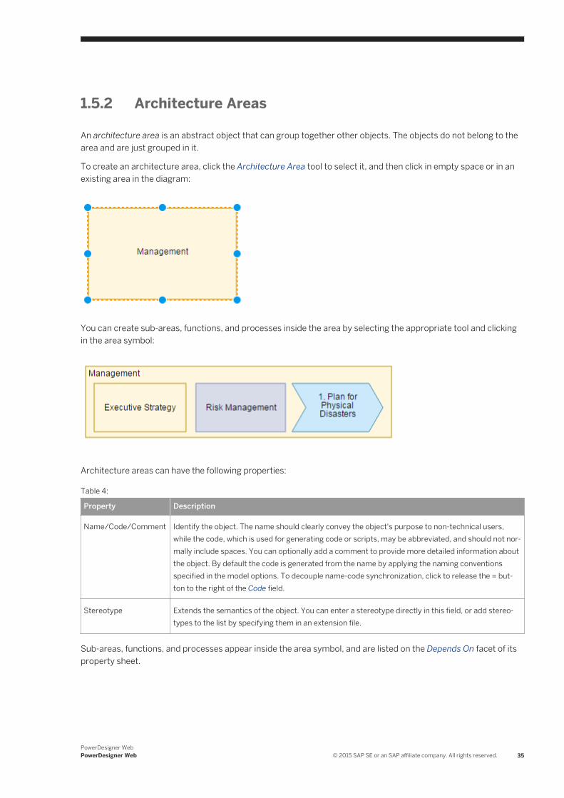
1.5.2 Architecture Areas
An architecture area is an abstract object that can group together other objects. The objects do not belong to the area and are just grouped in it.
To create an architecture area, click the Architecture Area tool to select it, and then click in empty space or in an existing area in the diagram:
You can create sub-areas, functions, and processes inside the area by selecting the appropriate tool and clicking in the area symbol:
Architecture areas can have the following properties:
Table 4:
Property Description
Name/Code/Comment Identify the object. The name should clearly convey the object's purpose to non-technical users, while the code, which is used for generating code or scripts, may be abbreviated, and should not normally include spaces. You can optionally add a comment to provide more detailed information about the object. By default the code is generated from the name by applying the naming conventions specified in the model options. To decouple name-code synchronization, click to release the = button to the right of the Code field.
Stereotype Extends the semantics of the object. You can enter a stereotype directly in this field, or add stereotypes to the list by specifying them in an extension file.
Sub-areas, functions, and processes appear inside the area symbol, and are listed on the Depends On facet of its property sheet.
PowerDesigner WebPowerDesigner Web © 2015 SAP SE or an SAP affiliate company. All rights reserved. 35
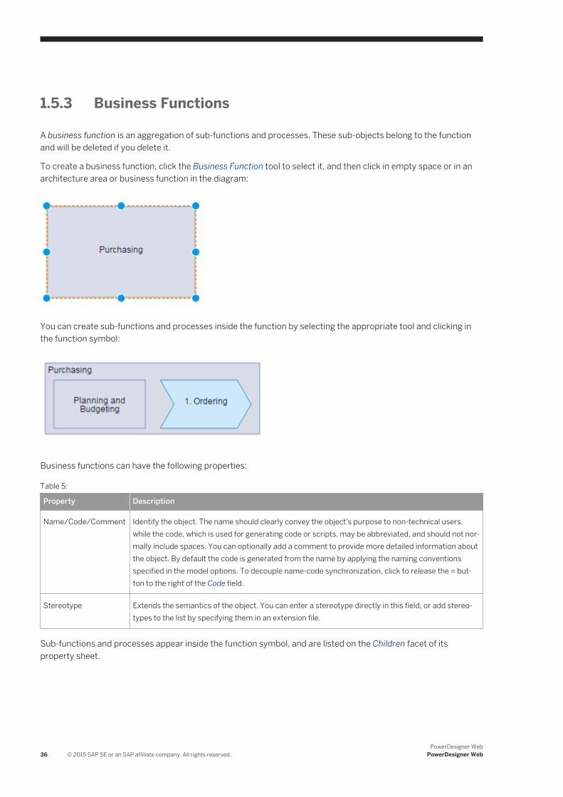
1.5.3 Business Functions
A business function is an aggregation of sub-functions and processes. These sub-objects belong to the function and will be deleted if you delete it.
To create a business function, click the Business Function tool to select it, and then click in empty space or in an architecture area or business function in the diagram:
You can create sub-functions and processes inside the function by selecting the appropriate tool and clicking in the function symbol:
Business functions can have the following properties:
Table 5:
Property Description
Name/Code/Comment Identify the object. The name should clearly convey the object's purpose to non-technical users, while the code, which is used for generating code or scripts, may be abbreviated, and should not normally include spaces. You can optionally add a comment to provide more detailed information about the object. By default the code is generated from the name by applying the naming conventions specified in the model options. To decouple name-code synchronization, click to release the = button to the right of the Code field.
Stereotype Extends the semantics of the object. You can enter a stereotype directly in this field, or add stereotypes to the list by specifying them in an extension file.
Sub-functions and processes appear inside the function symbol, and are listed on the Children facet of its property sheet.
36 © 2015 SAP SE or an SAP affiliate company. All rights reserved.PowerDesigner Web
PowerDesigner Web
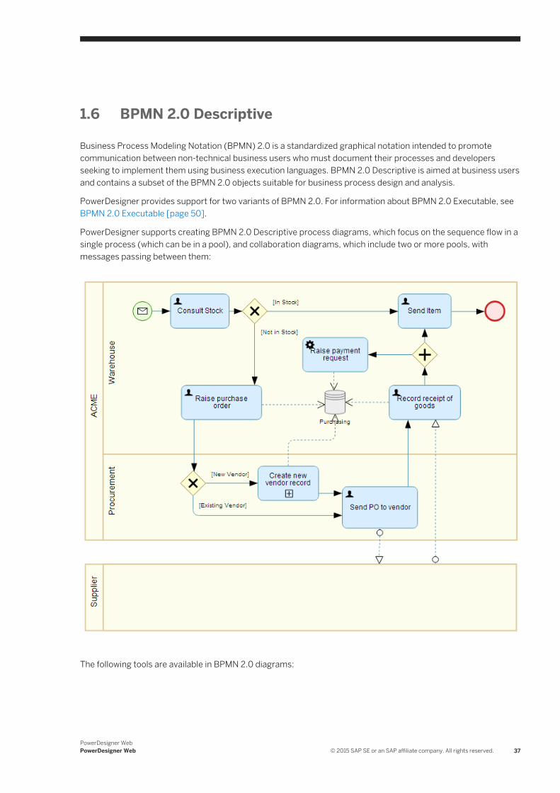
1.6 BPMN 2.0 Descriptive
Business Process Modeling Notation (BPMN) 2.0 is a standardized graphical notation intended to promote communication between non-technical business users who must document their processes and developers seeking to implement them using business execution languages. BPMN 2.0 Descriptive is aimed at business users and contains a subset of the BPMN 2.0 objects suitable for business process design and analysis.
PowerDesigner provides support for two variants of BPMN 2.0. For information about BPMN 2.0 Executable, see BPMN 2.0 Executable [page 50].
PowerDesigner supports creating BPMN 2.0 Descriptive process diagrams, which focus on the sequence flow in a single process (which can be in a pool), and collaboration diagrams, which include two or more pools, with messages passing between them:
The following tools are available in BPMN 2.0 diagrams:
PowerDesigner WebPowerDesigner Web © 2015 SAP SE or an SAP affiliate company. All rights reserved. 37
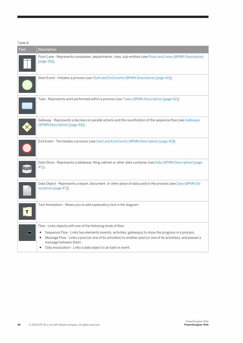
Table 6:
Tool Description
Pool/Lane - Represents companies, departments, roles, sub-entities (see Pools and Lanes (BPMN Descriptive) [page 39]).
Start Event - Initiates a process (see Start and End Events (BPMN Descriptive) [page 40]).
Task - Represents work performed within a process (see Tasks (BPMN Descriptive) [page 42]).
Gateway - Represents a decision or parallel actions and the reunification of the sequence flow (see Gateways (BPMN Descriptive) [page 44]).
End Event - Terminates a process (see Start and End Events (BPMN Descriptive) [page 40]).
Data Store - Represents a database, filing cabinet or other data container (see Data (BPMN Descriptive) [page 47]).
Data Object - Represents a report, document, or other piece of data used in the process (see Data (BPMN Descriptive) [page 47]).
Text Annotation - Allows you to add explanatory text in the diagram.
Flow - Links objects with one of the following kinds of flow:
● Sequence Flow - Links two elements (events, activities, gateways) to show the progress in a process.● Message Flow - Links a pool (or one of its activities) to another pool (or one of its activities), and passes a
message between them.● Data Association - Links a data object to an task or event.
38 © 2015 SAP SE or an SAP affiliate company. All rights reserved.PowerDesigner Web
PowerDesigner Web
1.6.1 Pools and Lanes (BPMN Descriptive)
Pools represent companies, departments, or roles. Lanes represent sub-entities within these organizations and appear as swimlanes inside the pool. Many BPMN diagrams contain one or more pools, with all the other objects placed in the lanes of these pools.
NotePools can be vertical (top to bottom) or horizontal (left to right). You can change the orientation of your diagram (if it does not contain any pools) by selecting Menu Change Pool to Horizontal/Vertical .
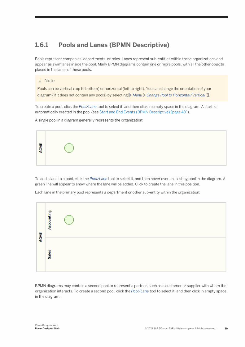
To create a pool, click the Pool/Lane tool to select it, and then click in empty space in the diagram. A start is automatically created in the pool (see Start and End Events (BPMN Descriptive) [page 40]).
A single pool in a diagram generally represents the organization:
To add a lane to a pool, click the Pool/Lane tool to select it, and then hover over an existing pool in the diagram. A green line will appear to show where the lane will be added. Click to create the lane in this position.
Each lane in the primary pool represents a department or other sub-entity within the organization:
BPMN diagrams may contain a second pool to represent a partner, such as a customer or supplier with whom the organization interacts. To create a second pool, click the Pool/Lane tool to select it, and then click in empty space in the diagram:
PowerDesigner WebPowerDesigner Web © 2015 SAP SE or an SAP affiliate company. All rights reserved. 39
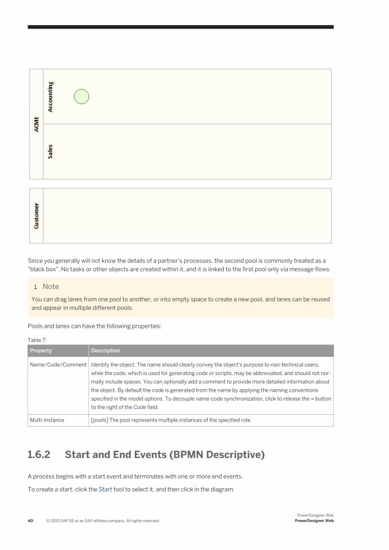
Since you generally will not know the details of a partner's processes, the second pool is commonly treated as a "black box". No tasks or other objects are created within it, and it is linked to the first pool only via message flows.
NoteYou can drag lanes from one pool to another, or into empty space to create a new pool, and lanes can be reused and appear in multiple different pools.
Pools and lanes can have the following properties:
Table 7:
Property Description
Name/Code/Comment Identify the object. The name should clearly convey the object's purpose to non-technical users, while the code, which is used for generating code or scripts, may be abbreviated, and should not normally include spaces. You can optionally add a comment to provide more detailed information about the object. By default the code is generated from the name by applying the naming conventions specified in the model options. To decouple name-code synchronization, click to release the = button to the right of the Code field.
Multi-instance [pools] The pool represents multiple instances of the specified role.
1.6.2 Start and End Events (BPMN Descriptive)
A process begins with a start event and terminates with one or more end events.
To create a start, click the Start tool to select it, and then click in the diagram.
40 © 2015 SAP SE or an SAP affiliate company. All rights reserved.PowerDesigner Web
PowerDesigner Web
NoteA start event is created by default when you create a pool (see Pools and Lanes (BPMN Descriptive) [page 39]).
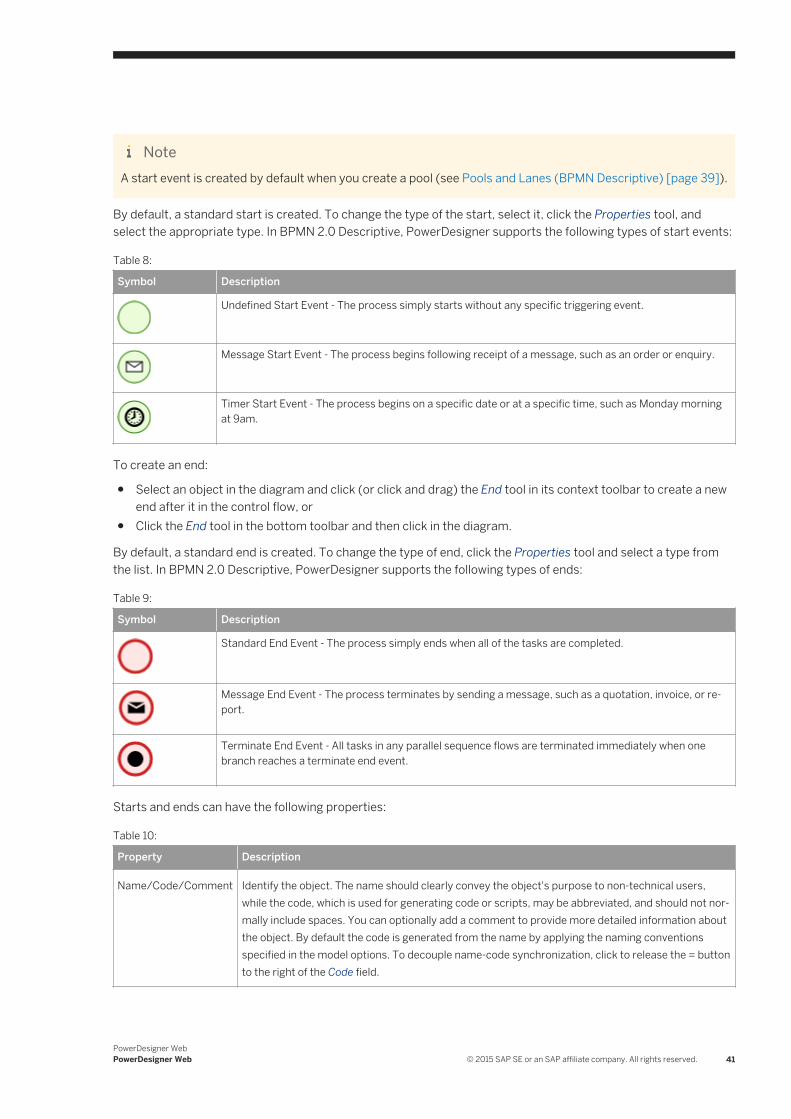
By default, a standard start is created. To change the type of the start, select it, click the Properties tool, and select the appropriate type. In BPMN 2.0 Descriptive, PowerDesigner supports the following types of start events:
Table 8:
Symbol Description
Undefined Start Event - The process simply starts without any specific triggering event.
Message Start Event - The process begins following receipt of a message, such as an order or enquiry.
Timer Start Event - The process begins on a specific date or at a specific time, such as Monday morning at 9am.
To create an end:
● Select an object in the diagram and click (or click and drag) the End tool in its context toolbar to create a new end after it in the control flow, or
● Click the End tool in the bottom toolbar and then click in the diagram.
By default, a standard end is created. To change the type of end, click the Properties tool and select a type from the list. In BPMN 2.0 Descriptive, PowerDesigner supports the following types of ends:
Table 9:
Symbol Description
Standard End Event - The process simply ends when all of the tasks are completed.
Message End Event - The process terminates by sending a message, such as a quotation, invoice, or report.
Terminate End Event - All tasks in any parallel sequence flows are terminated immediately when one branch reaches a terminate end event.
Starts and ends can have the following properties:
Table 10:
Property Description
Name/Code/Comment Identify the object. The name should clearly convey the object's purpose to non-technical users, while the code, which is used for generating code or scripts, may be abbreviated, and should not normally include spaces. You can optionally add a comment to provide more detailed information about the object. By default the code is generated from the name by applying the naming conventions specified in the model options. To decouple name-code synchronization, click to release the = button to the right of the Code field.
PowerDesigner WebPowerDesigner Web © 2015 SAP SE or an SAP affiliate company. All rights reserved. 41
1.6.3 Tasks (BPMN Descriptive)
The main contents of a process are the tasks that are performed during its execution.
To create a task:
● Select an object in the diagram and click (or click and drag) the Task tool in its context toolbar to create a new task after it in the control flow, or
● Click the Task tool in the bottom toolbar and click in the diagram.
The task is created with its default name highlighted, ready for you to enter an appropriate name.
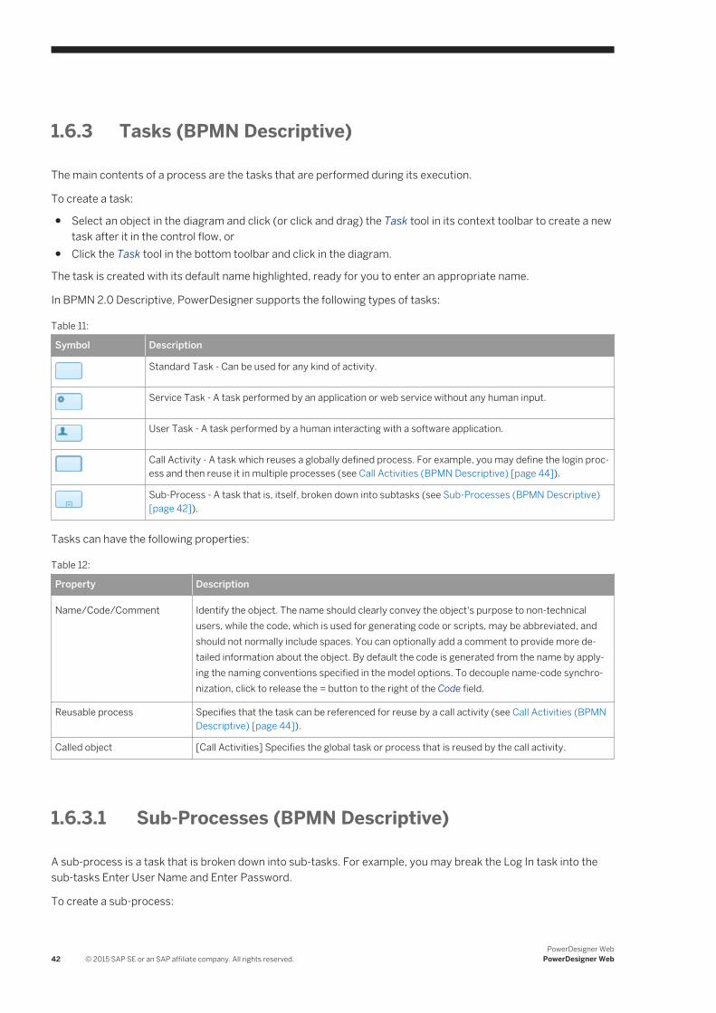
In BPMN 2.0 Descriptive, PowerDesigner supports the following types of tasks:
Table 11:
Symbol Description
Standard Task - Can be used for any kind of activity.
Service Task - A task performed by an application or web service without any human input.
User Task - A task performed by a human interacting with a software application.
Call Activity - A task which reuses a globally defined process. For example, you may define the login process and then reuse it in multiple processes (see Call Activities (BPMN Descriptive) [page 44]).
Sub-Process - A task that is, itself, broken down into subtasks (see Sub-Processes (BPMN Descriptive) [page 42]).
Tasks can have the following properties:
Table 12:
Property Description
Name/Code/Comment Identify the object. The name should clearly convey the object's purpose to non-technical users, while the code, which is used for generating code or scripts, may be abbreviated, and should not normally include spaces. You can optionally add a comment to provide more detailed information about the object. By default the code is generated from the name by applying the naming conventions specified in the model options. To decouple name-code synchronization, click to release the = button to the right of the Code field.
Reusable process Specifies that the task can be referenced for reuse by a call activity (see Call Activities (BPMN Descriptive) [page 44]).
Called object [Call Activities] Specifies the global task or process that is reused by the call activity.
1.6.3.1 Sub-Processes (BPMN Descriptive)
A sub-process is a task that is broken down into sub-tasks. For example, you may break the Log In task into the sub-tasks Enter User Name and Enter Password.
To create a sub-process:
42 © 2015 SAP SE or an SAP affiliate company. All rights reserved.PowerDesigner Web
PowerDesigner Web
● Select an object in the diagram and click (or click and drag) the Task tool to create a new task after it in the control flow, or
● Click the Task tool in the bottom toolbar and click in the diagram.
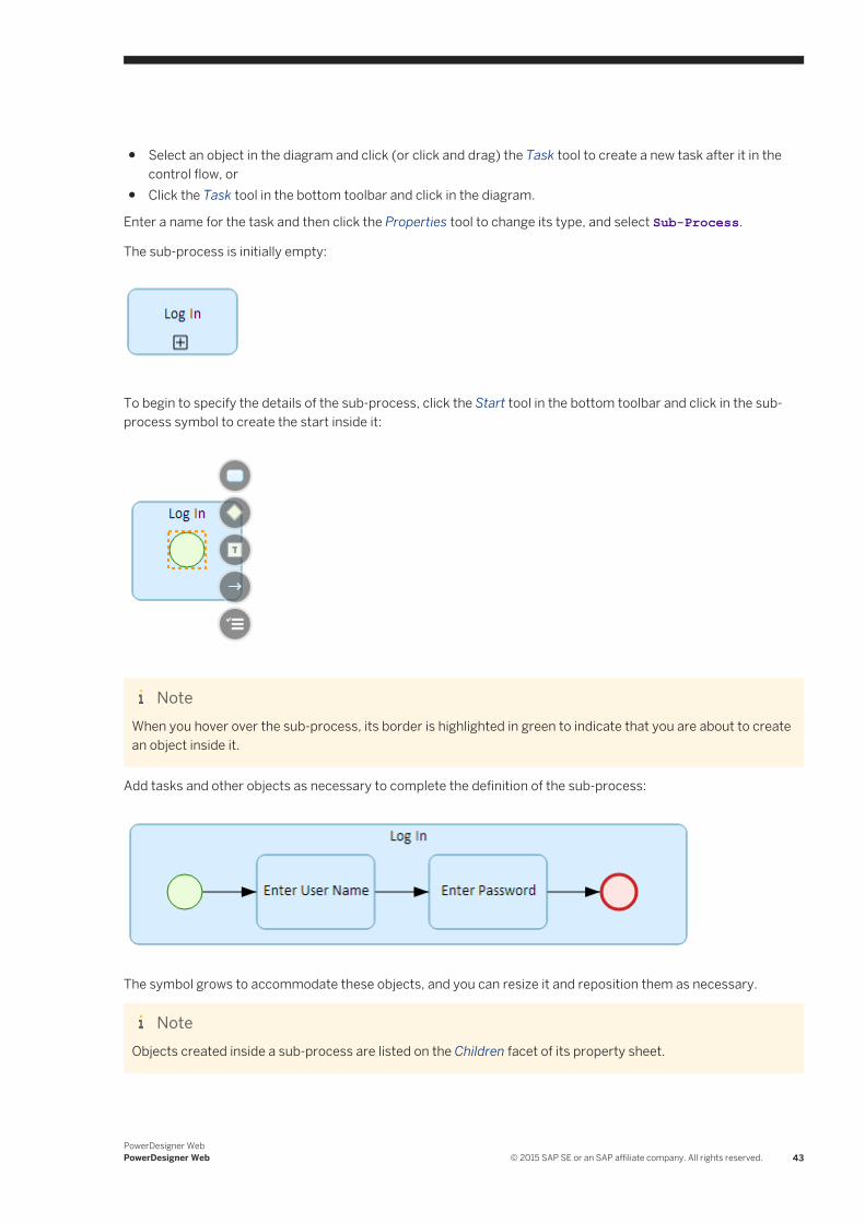
Enter a name for the task and then click the Properties tool to change its type, and select Sub-Process.
The sub-process is initially empty:
To begin to specify the details of the sub-process, click the Start tool in the bottom toolbar and click in the sub-process symbol to create the start inside it:
NoteWhen you hover over the sub-process, its border is highlighted in green to indicate that you are about to create an object inside it.
Add tasks and other objects as necessary to complete the definition of the sub-process:
The symbol grows to accommodate these objects, and you can resize it and reposition them as necessary.
NoteObjects created inside a sub-process are listed on the Children facet of its property sheet.
PowerDesigner WebPowerDesigner Web © 2015 SAP SE or an SAP affiliate company. All rights reserved. 43
1.6.3.2 Call Activities (BPMN Descriptive)
Call activities are tasks that reuse an existing global process or task. For example, you may define a process called Log In and then reuse it in various other processes.
To create a call activity, first create a task:
● Select an object in the diagram and click (or click and drag) the Task tool in its context toolbar to create a new task after it in the control flow, or
● Click the Task tool in the bottom toolbar and click in the diagram.
Enter a name for the task and then click the Properties tool in its context toolbar to change its type, and select Call Activity.
To specify the task that will be reused, go to the Properties panel, click the Select Object button to the right of the Called object field, and select the task to reuse from the list.
NoteThe tasks that are available to be reused from this list must:
● Have the property Reusable Process selected, and● Be saved in either the current diagram or in the repository Library folder.
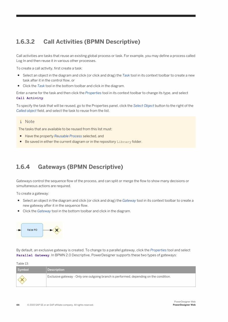
1.6.4 Gateways (BPMN Descriptive)
Gateways control the sequence flow of the process, and can split or merge the flow to show many decisions or simultaneous actions are required.
To create a gateway:
● Select an object in the diagram and click (or click and drag) the Gateway tool in its context toolbar to create a new gateway after it in the sequence flow.
● Click the Gateway tool in the bottom toolbar and click in the diagram.
By default, an exclusive gateway is created. To change to a parallel gateway, click the Properties tool and select Parallel Gateway. In BPMN 2.0 Descriptive, PowerDesigner supports these two types of gateways:
Table 13:
Symbol Description
Exclusive gateway - Only one outgoing branch is performed, depending on the condition.
44 © 2015 SAP SE or an SAP affiliate company. All rights reserved.PowerDesigner Web
PowerDesigner Web
Symbol Description
Parallel gateway - All outgoing branches are performed simultaneously.
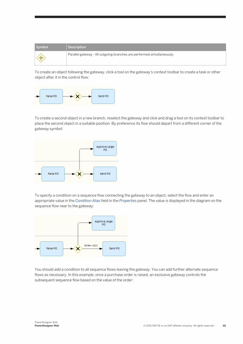
To create an object following the gateway, click a tool on the gateway's context toolbar to create a task or other object after it in the control flow:
To create a second object in a new branch, reselect the gateway and click and drag a tool on its context toolbar to place the second object in a suitable position. By preference its flow should depart from a different corner of the gateway symbol:
To specify a condition on a sequence flow connecting the gateway to an object, select the flow and enter an appropriate value in the Condition Alias field in the Properties panel. The value is displayed in the diagram on the sequence flow near to the gateway:
You should add a condition to all sequence flows leaving the gateway. You can add further alternate sequence flows as necessary. In this example, once a purchase order is raised, an exclusive gateway controls the subsequent sequence flow based on the value of the order:
PowerDesigner WebPowerDesigner Web © 2015 SAP SE or an SAP affiliate company. All rights reserved. 45
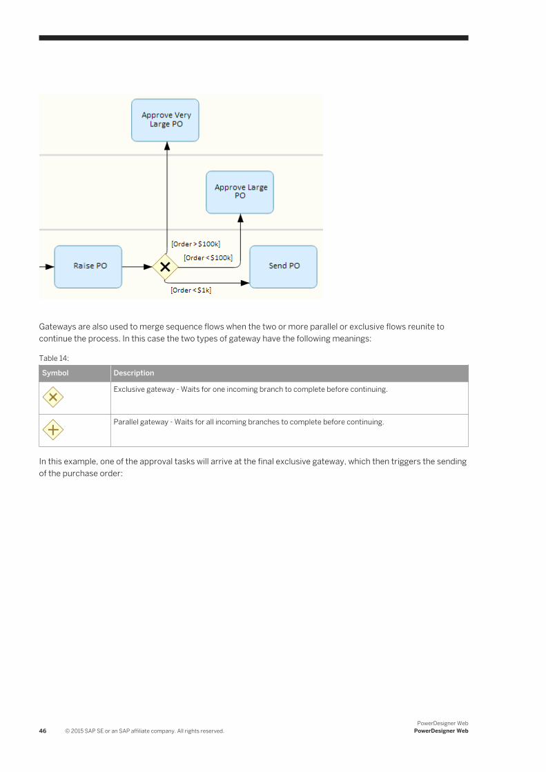
Gateways are also used to merge sequence flows when the two or more parallel or exclusive flows reunite to continue the process. In this case the two types of gateway have the following meanings:
Table 14:
Symbol Description
Exclusive gateway - Waits for one incoming branch to complete before continuing.
Parallel gateway - Waits for all incoming branches to complete before continuing.
In this example, one of the approval tasks will arrive at the final exclusive gateway, which then triggers the sending of the purchase order:
46 © 2015 SAP SE or an SAP affiliate company. All rights reserved.PowerDesigner Web
PowerDesigner Web
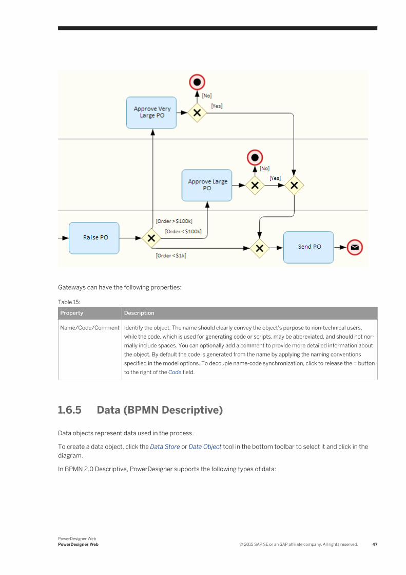
Gateways can have the following properties:
Table 15:
Property Description
Name/Code/Comment Identify the object. The name should clearly convey the object's purpose to non-technical users, while the code, which is used for generating code or scripts, may be abbreviated, and should not normally include spaces. You can optionally add a comment to provide more detailed information about the object. By default the code is generated from the name by applying the naming conventions specified in the model options. To decouple name-code synchronization, click to release the = button to the right of the Code field.
1.6.5 Data (BPMN Descriptive)
Data objects represent data used in the process.
To create a data object, click the Data Store or Data Object tool in the bottom toolbar to select it and click in the diagram.
In BPMN 2.0 Descriptive, PowerDesigner supports the following types of data:
PowerDesigner WebPowerDesigner Web © 2015 SAP SE or an SAP affiliate company. All rights reserved. 47
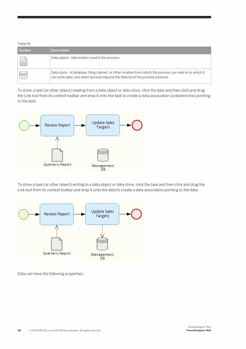
Table 16:
Symbol Description
Data object - Information used in the process.
Data store - A database, filing cabinet, or other location from which the process can read or to which it can write data, and which persists beyond the lifetime of the process instance.
To show a task (or other object) reading from a data object or data store, click the data and then click and drag the Link tool from its context toolbar and drop it onto the task to create a data association (a dashed line) pointing to the task:
To show a task (or other object) writing to a data object or data store, click the task and then click and drag the Link tool from its context toolbar and drop it onto the data to create a data association pointing to the data:
Data can have the following properties:
48 © 2015 SAP SE or an SAP affiliate company. All rights reserved.PowerDesigner Web
PowerDesigner Web
Table 17:
Property Description
Name/Code/Comment Identify the object. The name should clearly convey the object's purpose to non-technical users, while the code, which is used for generating code or scripts, may be abbreviated, and should not normally include spaces. You can optionally add a comment to provide more detailed information about the object. By default the code is generated from the name by applying the naming conventions specified in the model options. To decouple name-code synchronization, click to release the = button to the right of the Code field.
Collection [data objects] Specifies that the object represents a collection of elements.
Capacity / Unlimited [data stores] Specify the capacity of the store either as a numeric value or as unlimited.
1.6.6 Sequence and Message Flows (BPMN Descriptive)
Sequence flows are solid lines with an arrow at one end, which link the elements in a process in the diagram or in a single pool and show the order in which they are performed. Message flows are dotted lines with an arrow at one end, which link two separate pools (or elements in two separate pools) and show the direction in which the message is sent.
A sequence or message flow is created automatically when you create an object from the context toolbar of another object. To create a sequence flow explicitly:
● Select an object in the diagram, click the Link tool in its context toolbar, and drag it to another element in the same pool, or
● Click the Link tool in the bottom toolbar to select it, and then click and drag from one element to another in a single pool.
To create a message flow explicitly:
● Select an object in the diagram, click the Link tool in its context toolbar, and drag it to another pool (or an element in another pool), or
● Click the Link tool in the bottom toolbar to select it and then click and drag from one pool (or an element in the pool) to another pool (or an element in the other pool).
PowerDesigner WebPowerDesigner Web © 2015 SAP SE or an SAP affiliate company. All rights reserved. 49
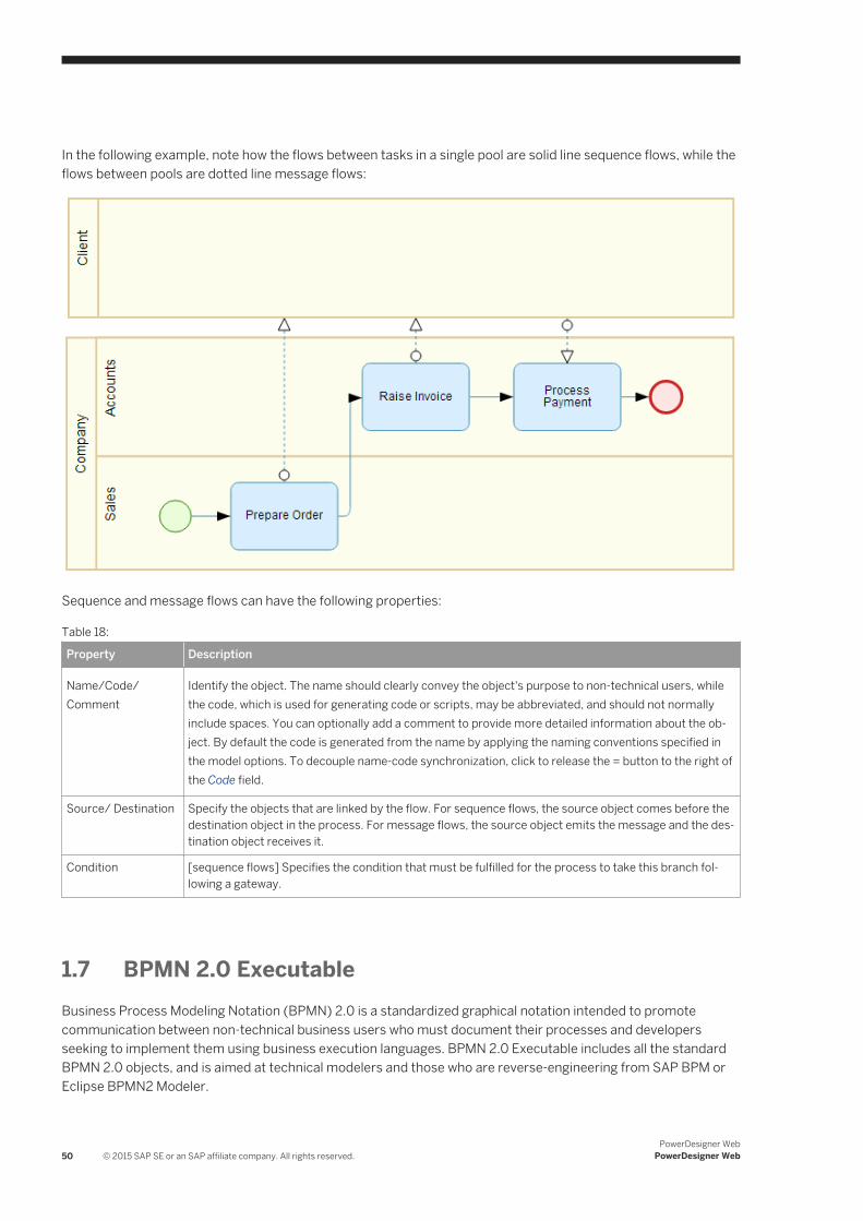
In the following example, note how the flows between tasks in a single pool are solid line sequence flows, while the flows between pools are dotted line message flows:
Sequence and message flows can have the following properties:
Table 18:
Property Description
Name/Code/Comment
Identify the object. The name should clearly convey the object's purpose to non-technical users, while the code, which is used for generating code or scripts, may be abbreviated, and should not normally include spaces. You can optionally add a comment to provide more detailed information about the object. By default the code is generated from the name by applying the naming conventions specified in the model options. To decouple name-code synchronization, click to release the = button to the right of the Code field.
Source/ Destination Specify the objects that are linked by the flow. For sequence flows, the source object comes before the destination object in the process. For message flows, the source object emits the message and the destination object receives it.
Condition [sequence flows] Specifies the condition that must be fulfilled for the process to take this branch following a gateway.
1.7 BPMN 2.0 ExecutableBusiness Process Modeling Notation (BPMN) 2.0 is a standardized graphical notation intended to promote communication between non-technical business users who must document their processes and developers seeking to implement them using business execution languages. BPMN 2.0 Executable includes all the standard BPMN 2.0 objects, and is aimed at technical modelers and those who are reverse-engineering from SAP BPM or Eclipse BPMN2 Modeler.
50 © 2015 SAP SE or an SAP affiliate company. All rights reserved.PowerDesigner Web
PowerDesigner Web
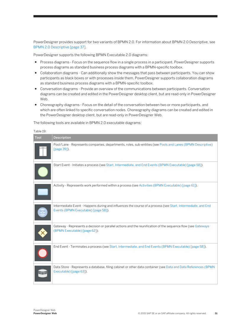
PowerDesigner provides support for two variants of BPMN 2.0. For information about BPMN 2.0 Descriptive, see BPMN 2.0 Descriptive [page 37].
PowerDesigner supports the following BPMN Executable 2.0 diagrams:
● Process diagrams - Focus on the sequence flow in a single process in a participant. PowerDesigner supports process diagrams as standard business process diagrams with a BPMN-specific toolbox.
● Collaboration diagrams - Can additionally show the messages that pass between participants. You can show participants as black boxes or with processes inside them. PowerDesigner supports collaboration diagrams as standard business process diagrams with a BPMN-specific toolbox.
● Conversation diagrams - Provide an overview of the communications between participants. Conversation diagrams can be created and edited in the PowerDesigner desktop client, but are read-only in PowerDesigner Web.
● Choreography diagrams - Focus on the detail of the conversation between two or more participants, and which are often linked to specific conversation nodes. Choreography diagrams can be created and edited in the PowerDesigner desktop client, but are read-only in PowerDesigner Web.
The following tools are available in BPMN 2.0 executable diagrams:
Table 19:
Tool Description
Pool/Lane - Represents companies, departments, roles, sub-entities (see Pools and Lanes (BPMN Descriptive) [page 39]).
Start Event - Initiates a process (see Start, Intermediate, and End Events (BPMN Executable) [page 58]).
Activity - Represents work performed within a process (see Activities (BPMN Executable) [page 61]).
Intermediate Event - Happens during and influences the course of a process (see Start, Intermediate, and End Events (BPMN Executable) [page 58]).
Gateway - Represents a decision or parallel actions and the reunification of the sequence flow (see Gateways (BPMN Executable) [page 62]).
End Event - Terminates a process (see Start, Intermediate, and End Events (BPMN Executable) [page 58]).
Data Store - Represents a database, filing cabinet or other data container (see Data and Data References (BPMN Executable) [page 63]).
PowerDesigner WebPowerDesigner Web © 2015 SAP SE or an SAP affiliate company. All rights reserved. 51
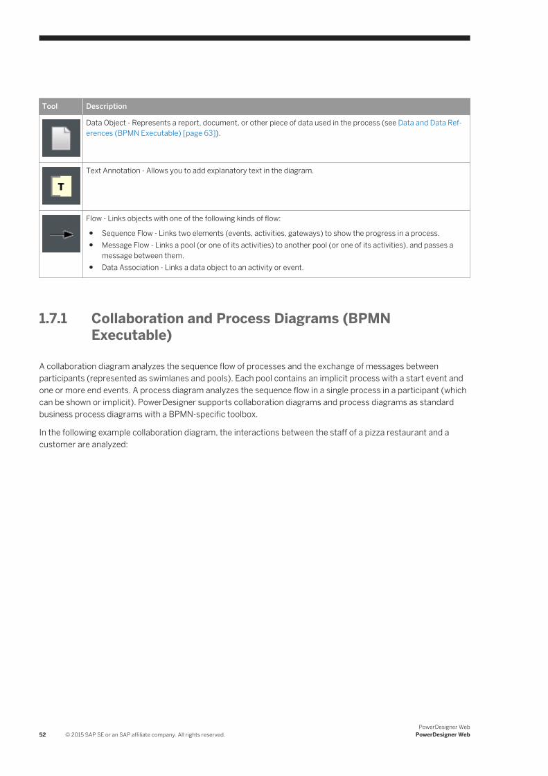
Tool Description
Data Object - Represents a report, document, or other piece of data used in the process (see Data and Data References (BPMN Executable) [page 63]).
Text Annotation - Allows you to add explanatory text in the diagram.
Flow - Links objects with one of the following kinds of flow:
● Sequence Flow - Links two elements (events, activities, gateways) to show the progress in a process.● Message Flow - Links a pool (or one of its activities) to another pool (or one of its activities), and passes a
message between them.● Data Association - Links a data object to an activity or event.
1.7.1 Collaboration and Process Diagrams (BPMN Executable)
A collaboration diagram analyzes the sequence flow of processes and the exchange of messages between participants (represented as swimlanes and pools). Each pool contains an implicit process with a start event and one or more end events. A process diagram analyzes the sequence flow in a single process in a participant (which can be shown or implicit). PowerDesigner supports collaboration diagrams and process diagrams as standard business process diagrams with a BPMN-specific toolbox.
In the following example collaboration diagram, the interactions between the staff of a pizza restaurant and a customer are analyzed:
52 © 2015 SAP SE or an SAP affiliate company. All rights reserved.PowerDesigner Web
PowerDesigner Web
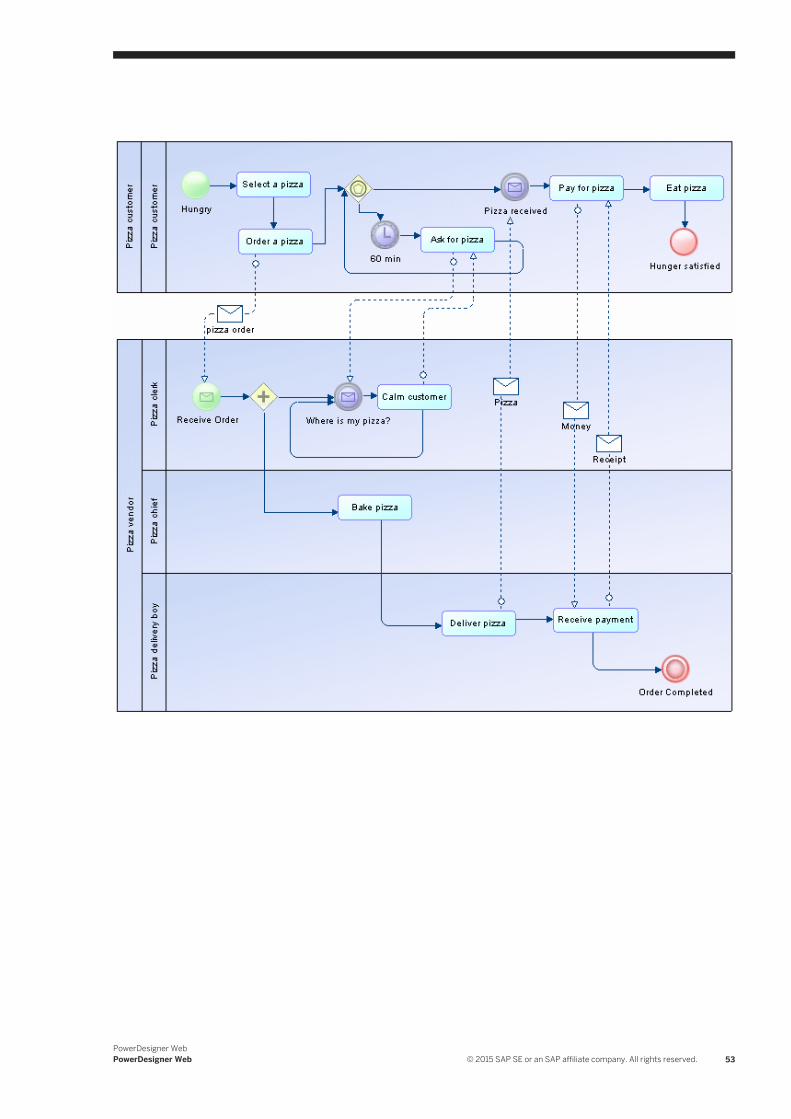
PowerDesigner WebPowerDesigner Web © 2015 SAP SE or an SAP affiliate company. All rights reserved. 53
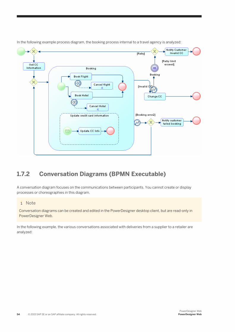
In the following example process diagram, the booking process internal to a travel agency is analyzed:
1.7.2 Conversation Diagrams (BPMN Executable)
A conversation diagram focuses on the communications between participants. You cannot create or display processes or choreographies in this diagram.
NoteConversation diagrams can be created and edited in the PowerDesigner desktop client, but are read-only in PowerDesigner Web.
In the following example, the various conversations associated with deliveries from a supplier to a retailer are analyzed:
54 © 2015 SAP SE or an SAP affiliate company. All rights reserved.PowerDesigner Web
PowerDesigner Web
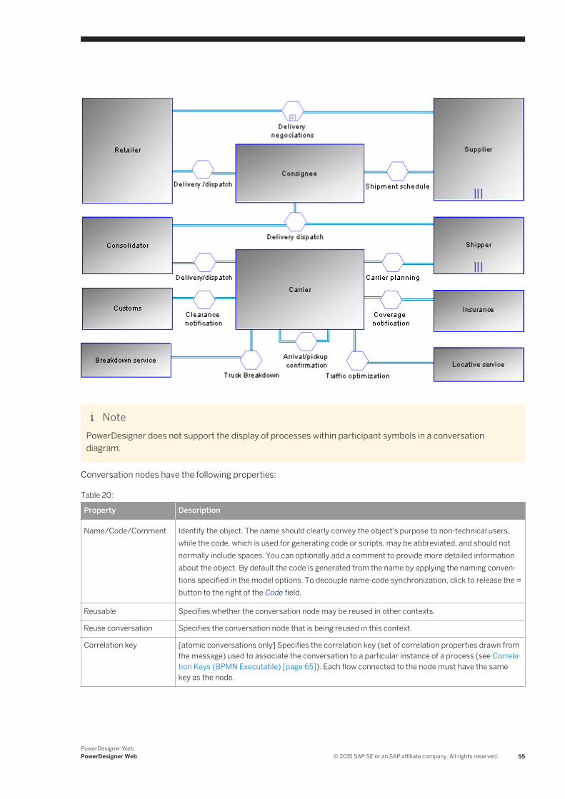
NotePowerDesigner does not support the display of processes within participant symbols in a conversation diagram.
Conversation nodes have the following properties:
Table 20:
Property Description
Name/Code/Comment Identify the object. The name should clearly convey the object's purpose to non-technical users, while the code, which is used for generating code or scripts, may be abbreviated, and should not normally include spaces. You can optionally add a comment to provide more detailed information about the object. By default the code is generated from the name by applying the naming conventions specified in the model options. To decouple name-code synchronization, click to release the = button to the right of the Code field.
Reusable Specifies whether the conversation node may be reused in other contexts.
Reuse conversation Specifies the conversation node that is being reused in this context.
Correlation key [atomic conversations only] Specifies the correlation key (set of correlation properties drawn from the message) used to associate the conversation to a particular instance of a process (see Correlation Keys (BPMN Executable) [page 65]). Each flow connected to the node must have the same key as the node.
PowerDesigner WebPowerDesigner Web © 2015 SAP SE or an SAP affiliate company. All rights reserved. 55
NoteYou can associate a conversation node with a choreography diagram or with a choreography task in order to model the choreography of the messages that flow through it. Choreography diagrams and tasks associated with a conversation node are initialized with the participants linked to the node:
● To associate a choreography diagram with a conversation node from the choreography diagram, right-click the diagram background and select Diagram Properties , and then select the appropriate node in the Related node list on the General tab of the diagram property sheet. Any choreography tasks you create in the diagram will be initialized with the participants associated with the node.
● To associate a choreography task with a conversation node from the task property sheet, select the appropriate node in the Related node list on the General tab of the task property sheet. The task participants will be set to the participants associated with the node.
● To associate a conversation node with an existing choreography diagram from the conversation node symbol, right-click the symbol and select Related Diagram <DiagramName> . Alternately, you can create a new choreography diagram from a conversation node, by selecting Related Diagram New . In both cases, to complete the link, you must open the choreography diagram property sheet and select the node in the Related node list. Any choreography tasks you create in the diagram will be initialized with the participants associated with the node.
Conversation links have the following properties:
Table 21:
Property Description
Name/Code/Comment Identify the object. The name should clearly convey the object's purpose to non-technical users, while the code, which is used for generating code or scripts, may be abbreviated, and should not normally include spaces. You can optionally add a comment to provide more detailed information about the object. By default the code is generated from the name by applying the naming conventions specified in the model options. To decouple name-code synchronization, click to release the = button to the right of the Code field.
Participant Specifies the participant to which the link is joined.
Conversation node Specifies the conversation node to which the link is joined. Use the tools to the right of the list to create, browse for, or view the properties of the currently selected object.
1.7.3 Choreography Diagrams (BPMN Executable)
A choreography diagram is used to analyze how participants exchange information to coordinate their interactions. A choreography diagram can be used to expand and analyze in detail the exchange of messages associated with a conversation node in a conversation diagram.
NoteChoreography diagrams can be created and edited in the PowerDesigner desktop client, but are read-only in PowerDesigner Web.
In the following example, the exchange of messages between a patient and a doctor is analyzed:
56 © 2015 SAP SE or an SAP affiliate company. All rights reserved.PowerDesigner Web
PowerDesigner Web
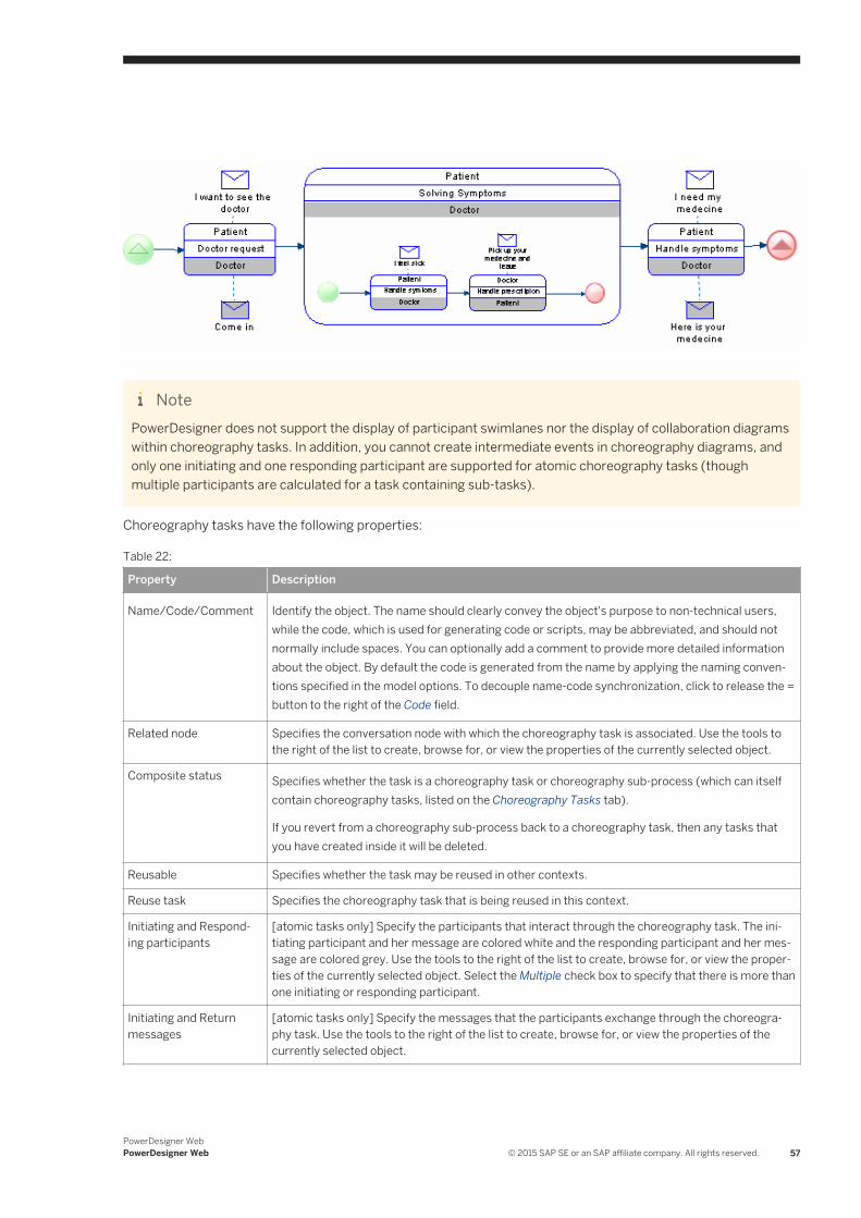
NotePowerDesigner does not support the display of participant swimlanes nor the display of collaboration diagrams within choreography tasks. In addition, you cannot create intermediate events in choreography diagrams, and only one initiating and one responding participant are supported for atomic choreography tasks (though multiple participants are calculated for a task containing sub-tasks).
Choreography tasks have the following properties:
Table 22:
Property Description
Name/Code/Comment Identify the object. The name should clearly convey the object's purpose to non-technical users, while the code, which is used for generating code or scripts, may be abbreviated, and should not normally include spaces. You can optionally add a comment to provide more detailed information about the object. By default the code is generated from the name by applying the naming conventions specified in the model options. To decouple name-code synchronization, click to release the = button to the right of the Code field.
Related node Specifies the conversation node with which the choreography task is associated. Use the tools to the right of the list to create, browse for, or view the properties of the currently selected object.
Composite status Specifies whether the task is a choreography task or choreography sub-process (which can itself contain choreography tasks, listed on the Choreography Tasks tab).
If you revert from a choreography sub-process back to a choreography task, then any tasks that you have created inside it will be deleted.
Reusable Specifies whether the task may be reused in other contexts.
Reuse task Specifies the choreography task that is being reused in this context.
Initiating and Responding participants
[atomic tasks only] Specify the participants that interact through the choreography task. The initiating participant and her message are colored white and the responding participant and her message are colored grey. Use the tools to the right of the list to create, browse for, or view the properties of the currently selected object. Select the Multiple check box to specify that there is more than one initiating or responding participant.
Initiating and Return messages
[atomic tasks only] Specify the messages that the participants exchange through the choreography task. Use the tools to the right of the list to create, browse for, or view the properties of the currently selected object.
PowerDesigner WebPowerDesigner Web © 2015 SAP SE or an SAP affiliate company. All rights reserved. 57
Property Description
Loop characteristics Specifies that the task is a loop or multiple-instance (parallel or sequential) choreography task.
1.7.4 Pools and Lanes (BPMN Executable)
Pools represent companies, departments, or roles. Lanes represent sub-entities within these organizations and appear as swimlanes inside the pool. Many BPMN diagrams contain one or more pools, with all the other objects placed in the lanes of these pools.
BPMN Executable pools and lanes behave in the same way as those in BPMN Descriptive (see Pools and Lanes (BPMN Descriptive) [page 39]).
In BPMN Executable, pools and lanes can also appear in conversation diagrams as square nodes (see Conversation Diagrams (BPMN Executable) [page 54]) and in choreography diagrams, where they do not have a separate symbol but are displayed on the top or bottom band of the choreography task symbol (see Choreography Diagrams (BPMN Executable) [page 56]).
1.7.5 Start, Intermediate, and End Events (BPMN Executable)
An event is something that happens during the course of a process. Events include the start and end of an activity, and any other intermediate happenings (such as a change of state or receipt of a message) which will affect its sequence or timing.
In BPMN Executable, various different types of start, intermediate and end events can be created depending on the context, and their type is indicated by their symbols. PowerDesigner supports all the types of events defined in BPMN 2.0:
● None - Untyped events, which indicate start points, state changes, and final states.● Message - Receiving and sending messages.● Timer - Cyclic timer events, points in time, time spans, or timeouts.● Escalation - Escalating to a higher level of responsibility.● Conditional - Reacting to changed business conditions or integrating business rules.● Link - Off-page connectors. Two corresponding link events equal a sequence flow.● Error - Catching or throwing named errors.● Cancel - Reacting to canceled transactions or triggering cancellation.● Compensation - Handling or triggering compensation.● Signal - Signaling across different processes. A signal thrown can be caught multiple times.● Multiple - Catching one out of a set of events. Throwing all events defined.● Parallel multiple - Catching all out of a set of parallel events.● Terminate - Triggering the immediate termination of a process.
58 © 2015 SAP SE or an SAP affiliate company. All rights reserved.PowerDesigner Web
PowerDesigner Web
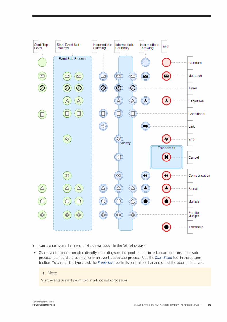
You can create events in the contexts shown above in the following ways:
● Start events - can be created directly in the diagram, in a pool or lane, in a standard or transaction sub-process (standard starts only), or in an event-based sub-process. Use the Start Event tool in the bottom toolbar. To change the type, click the Properties tool in its context toolbar and select the appropriate type.
NoteStart events are not permitted in ad hoc sub-processes.
PowerDesigner WebPowerDesigner Web © 2015 SAP SE or an SAP affiliate company. All rights reserved. 59
NoteTo make an event-based sub-process start event non-interrupting (with the dashed outer circle), deselect the Interrupting property.
● Intermediate catch events - can be created directly in the diagram, in a pool or lane, or in any type of sub-process. Use the Intermediate Catch Event tool in the context toolbar or the bottom toolbar to create the event. To change the type, click the Properties tool in its context toolbar and select the appropriate type.
● Intermediate boundary events - can be created on the edge of a task or of any type of sub-process. Use the Intermediate Catch Event tool in the context toolbar or the bottom toolbar, and click on the border of the task or sub-process. To change the type, click the Properties tool in its context toolbar and select the appropriate type.
NoteTo make an intermediate boundary event non-interrupting (with the dashed outer circles), deselect the Interrupting property.
● Intermediate throw events - can be created directly in the diagram, in a pool or lane, or in any type of sub-process. Use the Intermediate Catch Event tool in the context toolbar or the bottom toolbar, select the Properties tool from its context toolbar, select Intermediate Throw Event to change to the throw type, and then select the Properties tool again and select the appropriate type of throw event.
● End events - can be created directly in the diagram, in a pool or lane or in any type of sub-process. Use the End Event tool in the context toolbar or the bottom toolbar. To change the type, click the Properties tool in its context toolbar and select the appropriate type.
NoteEnd events are not permitted in ad hoc sub-processes. Cancel end events are only permitted in transactions.
Executable events can have the following properties:
Table 23:
Property Description
Name/Code/Comment Identify the object. The name should clearly convey the object's purpose to non-technical users, while the code, which is used for generating code or scripts, may be abbreviated, and should not normally include spaces. You can optionally add a comment to provide more detailed information about the object. By default the code is generated from the name by applying the naming conventions specified in the model options. To decouple name-code synchronization, click to release the = button to the right of the Code field.
Interrupting While most events interrupt the process modeled, event sub-process starts and intermediate boundary events can be specified as non-interrupting by deselecting this property. Non-interrupting events are marked by dashed outer circles.
Message [message events] Specifies the message that is associated with the event (see Messages (BPMN Executable) [page 65]).
60 © 2015 SAP SE or an SAP affiliate company. All rights reserved.PowerDesigner Web
PowerDesigner Web
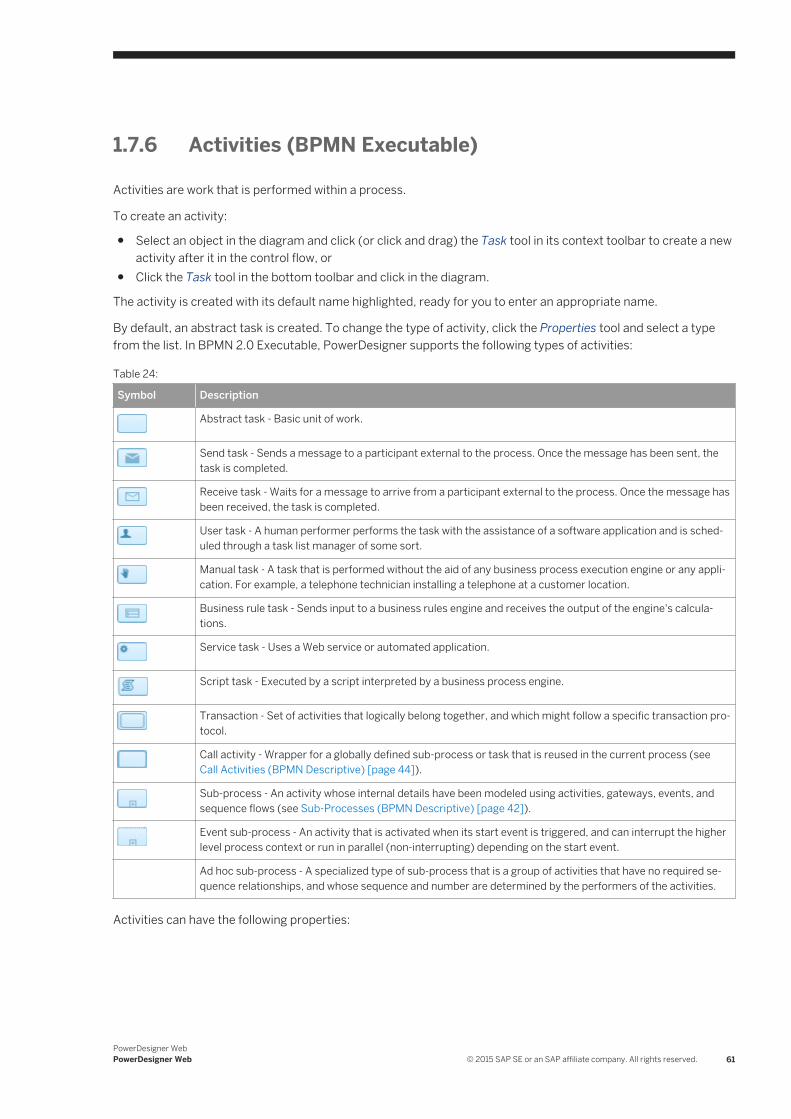
1.7.6 Activities (BPMN Executable)
Activities are work that is performed within a process.
To create an activity:
● Select an object in the diagram and click (or click and drag) the Task tool in its context toolbar to create a new activity after it in the control flow, or
● Click the Task tool in the bottom toolbar and click in the diagram.
The activity is created with its default name highlighted, ready for you to enter an appropriate name.
By default, an abstract task is created. To change the type of activity, click the Properties tool and select a type from the list. In BPMN 2.0 Executable, PowerDesigner supports the following types of activities:
Table 24:
Symbol Description
Abstract task - Basic unit of work.
Send task - Sends a message to a participant external to the process. Once the message has been sent, the task is completed.
Receive task - Waits for a message to arrive from a participant external to the process. Once the message has been received, the task is completed.
User task - A human performer performs the task with the assistance of a software application and is scheduled through a task list manager of some sort.
Manual task - A task that is performed without the aid of any business process execution engine or any application. For example, a telephone technician installing a telephone at a customer location.
Business rule task - Sends input to a business rules engine and receives the output of the engine's calculations.
Service task - Uses a Web service or automated application.
Script task - Executed by a script interpreted by a business process engine.
Transaction - Set of activities that logically belong together, and which might follow a specific transaction protocol.
Call activity - Wrapper for a globally defined sub-process or task that is reused in the current process (see Call Activities (BPMN Descriptive) [page 44]).
Sub-process - An activity whose internal details have been modeled using activities, gateways, events, and sequence flows (see Sub-Processes (BPMN Descriptive) [page 42]).
Event sub-process - An activity that is activated when its start event is triggered, and can interrupt the higher level process context or run in parallel (non-interrupting) depending on the start event.
Ad hoc sub-process - A specialized type of sub-process that is a group of activities that have no required sequence relationships, and whose sequence and number are determined by the performers of the activities.
Activities can have the following properties:
PowerDesigner WebPowerDesigner Web © 2015 SAP SE or an SAP affiliate company. All rights reserved. 61
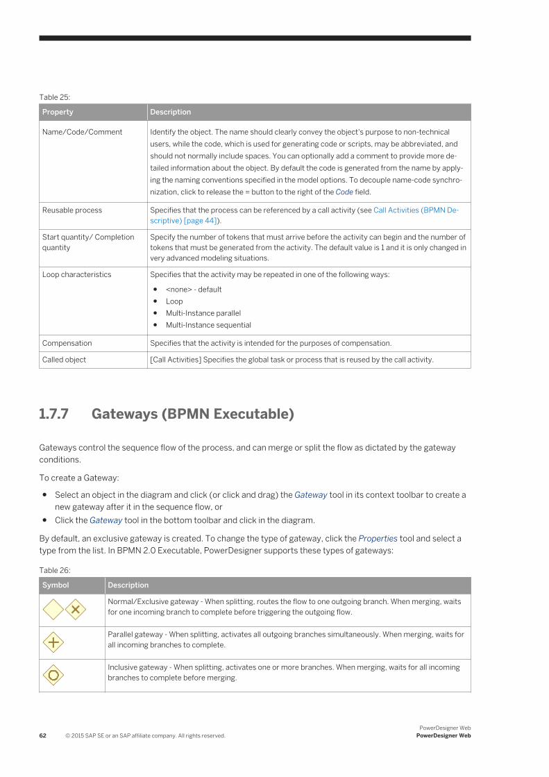
Table 25:
Property Description
Name/Code/Comment Identify the object. The name should clearly convey the object's purpose to non-technical users, while the code, which is used for generating code or scripts, may be abbreviated, and should not normally include spaces. You can optionally add a comment to provide more detailed information about the object. By default the code is generated from the name by applying the naming conventions specified in the model options. To decouple name-code synchronization, click to release the = button to the right of the Code field.
Reusable process Specifies that the process can be referenced by a call activity (see Call Activities (BPMN Descriptive) [page 44]).
Start quantity/ Completion quantity
Specify the number of tokens that must arrive before the activity can begin and the number of tokens that must be generated from the activity. The default value is 1 and it is only changed in very advanced modeling situations.
Loop characteristics Specifies that the activity may be repeated in one of the following ways:
● <none> - default● Loop● Multi-Instance parallel● Multi-Instance sequential
Compensation Specifies that the activity is intended for the purposes of compensation.
Called object [Call Activities] Specifies the global task or process that is reused by the call activity.
1.7.7 Gateways (BPMN Executable)
Gateways control the sequence flow of the process, and can merge or split the flow as dictated by the gateway conditions.
To create a Gateway:
● Select an object in the diagram and click (or click and drag) the Gateway tool in its context toolbar to create a new gateway after it in the sequence flow, or
● Click the Gateway tool in the bottom toolbar and click in the diagram.
By default, an exclusive gateway is created. To change the type of gateway, click the Properties tool and select a type from the list. In BPMN 2.0 Executable, PowerDesigner supports these types of gateways:
Table 26:
Symbol Description
Normal/Exclusive gateway - When splitting, routes the flow to one outgoing branch. When merging, waits for one incoming branch to complete before triggering the outgoing flow.
Parallel gateway - When splitting, activates all outgoing branches simultaneously. When merging, waits for all incoming branches to complete.
Inclusive gateway - When splitting, activates one or more branches. When merging, waits for all incoming branches to complete before merging.
62 © 2015 SAP SE or an SAP affiliate company. All rights reserved.PowerDesigner Web
PowerDesigner Web
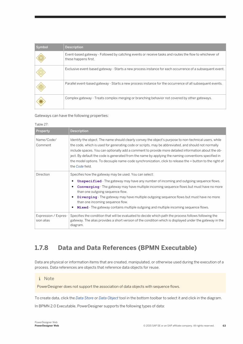
Symbol Description
Event-based gateway - Followed by catching events or receive tasks and routes the flow to whichever of these happens first.
Exclusive event-based gateway - Starts a new process instance for each occurrence of a subsequent event.
Parallel event-based gateway - Starts a new process instance for the occurrence of all subsequent events.
Complex gateway - Treats complex merging or branching behavior not covered by other gateways.
Gateways can have the following properties:
Table 27:
Property Description
Name/Code/Comment
Identify the object. The name should clearly convey the object's purpose to non-technical users, while the code, which is used for generating code or scripts, may be abbreviated, and should not normally include spaces. You can optionally add a comment to provide more detailed information about the object. By default the code is generated from the name by applying the naming conventions specified in the model options. To decouple name-code synchronization, click to release the = button to the right of the Code field.
Direction Specifies how the gateway may be used. You can select:
● Unspecified - The gateway may have any number of incoming and outgoing sequence flows.● Converging - The gateway may have multiple incoming sequence flows but must have no more
than one outgoing sequence flow.● Diverging - The gateway may have multiple outgoing sequence flows but must have no more
than one incoming sequence flow.● Mixed - The gateway contains multiple outgoing and multiple incoming sequence flows.
Expression / Expression alias
Specifies the condition that will be evaluated to decide which path the process follows following the gateway. The alias provides a short version of the condition which is displayed under the gateway in the diagram.
1.7.8 Data and Data References (BPMN Executable)
Data are physical or information items that are created, manipulated, or otherwise used during the execution of a process. Data references are objects that reference data objects for reuse.
NotePowerDesigner does not support the association of data objects with sequence flows.
To create data, click the Data Store or Data Object tool in the bottom toolbar to select it and click in the diagram.
In BPMN 2.0 Executable, PowerDesigner supports the following types of data:
PowerDesigner WebPowerDesigner Web © 2015 SAP SE or an SAP affiliate company. All rights reserved. 63
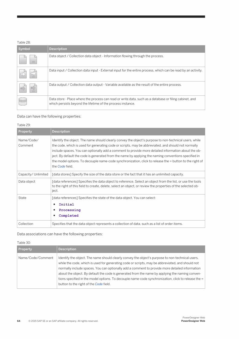
Table 28:
Symbol Description
Data object / Collection data object - Information flowing through the process.
Data input / Collection data input - External input for the entire process, which can be read by an activity.
Data output / Collection data output - Variable available as the result of the entire process.
Data store - Place where the process can read or write data, such as a database or filing cabinet, and which persists beyond the lifetime of the process instance.
Data can have the following properties:
Table 29:
Property Description
Name/Code/Comment
Identify the object. The name should clearly convey the object's purpose to non-technical users, while the code, which is used for generating code or scripts, may be abbreviated, and should not normally include spaces. You can optionally add a comment to provide more detailed information about the object. By default the code is generated from the name by applying the naming conventions specified in the model options. To decouple name-code synchronization, click to release the = button to the right of the Code field.
Capacity/ Unlimited [data stores] Specify the size of the data store or the fact that it has an unlimited capacity.
Data object [data references] Specifies the data object to reference. Select an object from the list, or use the tools to the right of this field to create, delete, select an object, or review the properties of the selected object.
State [data references] Specifies the state of the data object. You can select:
● Initial● Processing● Completed
Collection Specifies that the data object represents a collection of data, such as a list of order items.
Data associations can have the following properties:
Table 30:
Property Description
Name/Code/Comment Identify the object. The name should clearly convey the object's purpose to non-technical users, while the code, which is used for generating code or scripts, may be abbreviated, and should not normally include spaces. You can optionally add a comment to provide more detailed information about the object. By default the code is generated from the name by applying the naming conventions specified in the model options. To decouple name-code synchronization, click to release the = button to the right of the Code field.
64 © 2015 SAP SE or an SAP affiliate company. All rights reserved.PowerDesigner Web
PowerDesigner Web
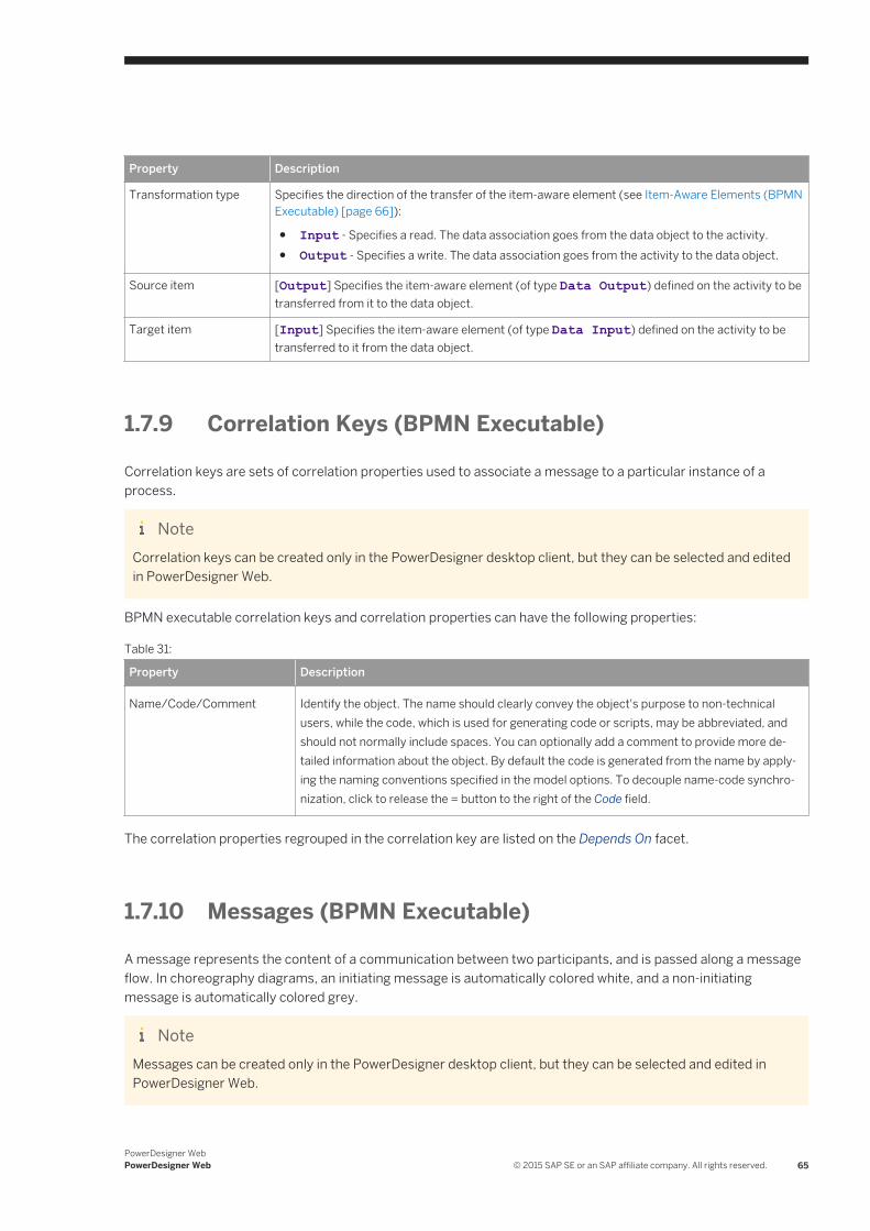
Property Description
Transformation type Specifies the direction of the transfer of the item-aware element (see Item-Aware Elements (BPMN Executable) [page 66]):
● Input - Specifies a read. The data association goes from the data object to the activity.● Output - Specifies a write. The data association goes from the activity to the data object.
Source item [Output] Specifies the item-aware element (of type Data Output) defined on the activity to be transferred from it to the data object.
Target item [Input] Specifies the item-aware element (of type Data Input) defined on the activity to be transferred to it from the data object.
1.7.9 Correlation Keys (BPMN Executable)
Correlation keys are sets of correlation properties used to associate a message to a particular instance of a process.
NoteCorrelation keys can be created only in the PowerDesigner desktop client, but they can be selected and edited in PowerDesigner Web.
BPMN executable correlation keys and correlation properties can have the following properties:
Table 31:
Property Description
Name/Code/Comment Identify the object. The name should clearly convey the object's purpose to non-technical users, while the code, which is used for generating code or scripts, may be abbreviated, and should not normally include spaces. You can optionally add a comment to provide more detailed information about the object. By default the code is generated from the name by applying the naming conventions specified in the model options. To decouple name-code synchronization, click to release the = button to the right of the Code field.
The correlation properties regrouped in the correlation key are listed on the Depends On facet.
1.7.10 Messages (BPMN Executable)
A message represents the content of a communication between two participants, and is passed along a message flow. In choreography diagrams, an initiating message is automatically colored white, and a non-initiating message is automatically colored grey.
NoteMessages can be created only in the PowerDesigner desktop client, but they can be selected and edited in PowerDesigner Web.
PowerDesigner WebPowerDesigner Web © 2015 SAP SE or an SAP affiliate company. All rights reserved. 65
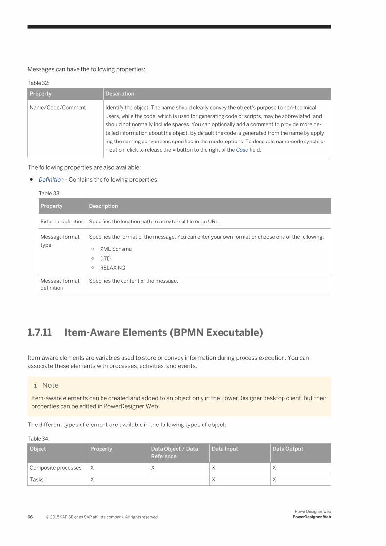
Messages can have the following properties:
Table 32:
Property Description
Name/Code/Comment Identify the object. The name should clearly convey the object's purpose to non-technical users, while the code, which is used for generating code or scripts, may be abbreviated, and should not normally include spaces. You can optionally add a comment to provide more detailed information about the object. By default the code is generated from the name by applying the naming conventions specified in the model options. To decouple name-code synchronization, click to release the = button to the right of the Code field.
The following properties are also available:
● Definition - Contains the following properties:
Table 33:
Property Description
External definition Specifies the location path to an external file or an URL.
Message format type
Specifies the format of the message. You can enter your own format or choose one of the following:
○ XML Schema○ DTD○ RELAX NG
Message format definition
Specifies the content of the message.
1.7.11 Item-Aware Elements (BPMN Executable)
Item-aware elements are variables used to store or convey information during process execution. You can associate these elements with processes, activities, and events.
NoteItem-aware elements can be created and added to an object only in the PowerDesigner desktop client, but their properties can be edited in PowerDesigner Web.
The different types of element are available in the following types of object:
Table 34:
Object Property Data Object / Data Reference
Data Input Data Output
Composite processes X X X X
Tasks X X X
66 © 2015 SAP SE or an SAP affiliate company. All rights reserved.PowerDesigner Web
PowerDesigner Web
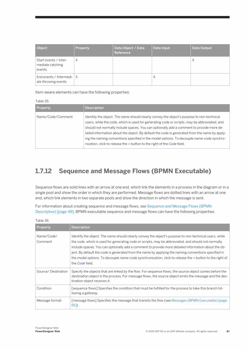
Object Property Data Object / Data Reference
Data Input Data Output
Start events / Intermediate catching events
X X
End events / Intermediate throwing events
X X
Item-aware elements can have the following properties:
Table 35:
Property Description
Name/Code/Comment Identify the object. The name should clearly convey the object's purpose to non-technical users, while the code, which is used for generating code or scripts, may be abbreviated, and should not normally include spaces. You can optionally add a comment to provide more detailed information about the object. By default the code is generated from the name by applying the naming conventions specified in the model options. To decouple name-code synchronization, click to release the = button to the right of the Code field.
1.7.12 Sequence and Message Flows (BPMN Executable)
Sequence flows are solid lines with an arrow at one end, which link the elements in a process in the diagram or in a single pool and show the order in which they are performed. Message flows are dotted lines with an arrow at one end, which link elements in two separate pools and show the direction in which the message is sent.
For information about creating sequence and message flows, see Sequence and Message Flows (BPMN Descriptive) [page 49]. BPMN executable sequence and message flows can have the following properties:
Table 36:
Property Description
Name/Code/Comment
Identify the object. The name should clearly convey the object's purpose to non-technical users, while the code, which is used for generating code or scripts, may be abbreviated, and should not normally include spaces. You can optionally add a comment to provide more detailed information about the object. By default the code is generated from the name by applying the naming conventions specified in the model options. To decouple name-code synchronization, click to release the = button to the right of the Code field.
Source/ Destination Specify the objects that are linked by the flow. For sequence flows, the source object comes before the destination object in the process. For message flows, the source object emits the message and the destination object receives it.
Condition [sequence flows] Specifies the condition that must be fulfilled for the process to take this branch following a gateway.
Message format [message flows] Specifies the message that transits the flow (see Messages (BPMN Executable) [page 65])
PowerDesigner WebPowerDesigner Web © 2015 SAP SE or an SAP affiliate company. All rights reserved. 67
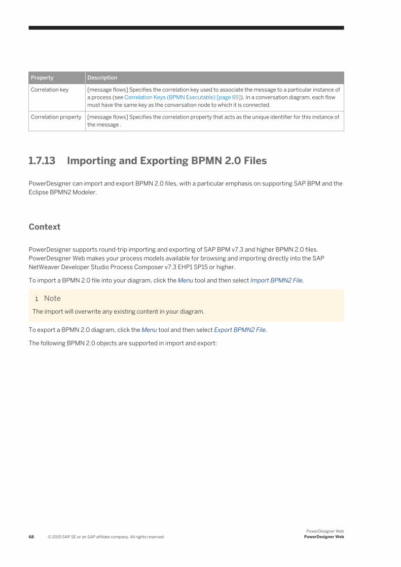
Property Description
Correlation key [message flows] Specifies the correlation key used to associate the message to a particular instance of a process (see Correlation Keys (BPMN Executable) [page 65]). In a conversation diagram, each flow must have the same key as the conversation node to which it is connected.
Correlation property [message flows] Specifies the correlation property that acts as the unique identifier for this instance of the message .
1.7.13 Importing and Exporting BPMN 2.0 Files
PowerDesigner can import and export BPMN 2.0 files, with a particular emphasis on supporting SAP BPM and the Eclipse BPMN2 Modeler.
Context
PowerDesigner supports round-trip importing and exporting of SAP BPM v7.3 and higher BPMN 2.0 files. PowerDesigner Web makes your process models available for browsing and importing directly into the SAP NetWeaver Developer Studio Process Composer v7.3 EHP1 SP15 or higher.
To import a BPMN 2.0 file into your diagram, click the Menu tool and then select Import BPMN2 File.
NoteThe import will overwrite any existing content in your diagram.
To export a BPMN 2.0 diagram, click the Menu tool and then select Export BPMN2 File.
The following BPMN 2.0 objects are supported in import and export:
68 © 2015 SAP SE or an SAP affiliate company. All rights reserved.PowerDesigner Web
PowerDesigner Web
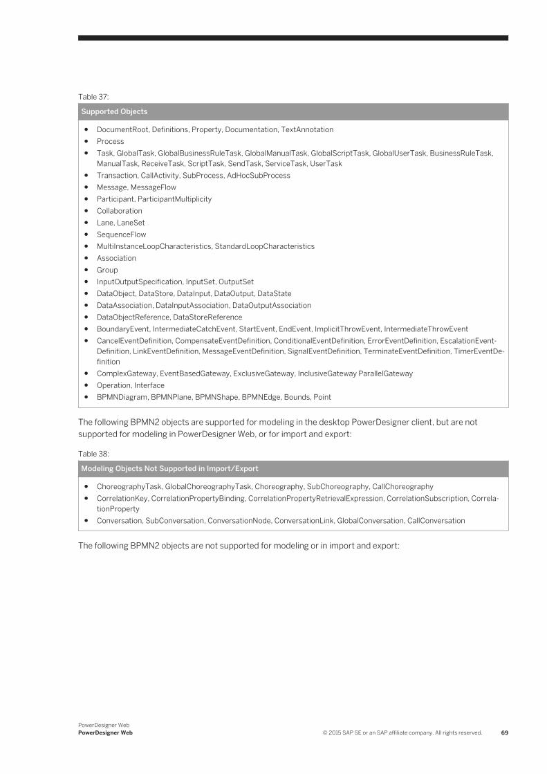
Table 37:
Supported Objects
● DocumentRoot, Definitions, Property, Documentation, TextAnnotation● Process● Task, GlobalTask, GlobalBusinessRuleTask, GlobalManualTask, GlobalScriptTask, GlobalUserTask, BusinessRuleTask,
ManualTask, ReceiveTask, ScriptTask, SendTask, ServiceTask, UserTask● Transaction, CallActivity, SubProcess, AdHocSubProcess● Message, MessageFlow● Participant, ParticipantMultiplicity● Collaboration● Lane, LaneSet● SequenceFlow● MultiInstanceLoopCharacteristics, StandardLoopCharacteristics● Association● Group● InputOutputSpecification, InputSet, OutputSet● DataObject, DataStore, DataInput, DataOutput, DataState● DataAssociation, DataInputAssociation, DataOutputAssociation● DataObjectReference, DataStoreReference● BoundaryEvent, IntermediateCatchEvent, StartEvent, EndEvent, ImplicitThrowEvent, IntermediateThrowEvent● CancelEventDefinition, CompensateEventDefinition, ConditionalEventDefinition, ErrorEventDefinition, EscalationEvent
Definition, LinkEventDefinition, MessageEventDefinition, SignalEventDefinition, TerminateEventDefinition, TimerEventDefinition
● ComplexGateway, EventBasedGateway, ExclusiveGateway, InclusiveGateway ParallelGateway● Operation, Interface● BPMNDiagram, BPMNPlane, BPMNShape, BPMNEdge, Bounds, Point
The following BPMN2 objects are supported for modeling in the desktop PowerDesigner client, but are not supported for modeling in PowerDesigner Web, or for import and export:
Table 38:
Modeling Objects Not Supported in Import/Export
● ChoreographyTask, GlobalChoreographyTask, Choreography, SubChoreography, CallChoreography● CorrelationKey, CorrelationPropertyBinding, CorrelationPropertyRetrievalExpression, CorrelationSubscription, Correla
tionProperty● Conversation, SubConversation, ConversationNode, ConversationLink, GlobalConversation, CallConversation
The following BPMN2 objects are not supported for modeling or in import and export:
PowerDesigner WebPowerDesigner Web © 2015 SAP SE or an SAP affiliate company. All rights reserved. 69
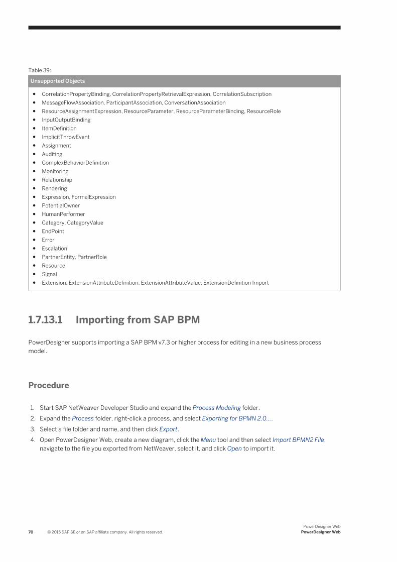
Table 39:
Unsupported Objects
● CorrelationPropertyBinding, CorrelationPropertyRetrievalExpression, CorrelationSubscription● MessageFlowAssociation, ParticipantAssociation, ConversationAssociation● ResourceAssignmentExpression, ResourceParameter, ResourceParameterBinding, ResourceRole● InputOutputBinding● ItemDefinition● ImplicitThrowEvent● Assignment● Auditing● ComplexBehaviorDefinition● Monitoring● Relationship● Rendering● Expression, FormalExpression● PotentialOwner● HumanPerformer● Category, CategoryValue● EndPoint● Error● Escalation● PartnerEntity, PartnerRole● Resource● Signal● Extension, ExtensionAttributeDefinition, ExtensionAttributeValue, ExtensionDefinition Import
1.7.13.1 Importing from SAP BPM
PowerDesigner supports importing a SAP BPM v7.3 or higher process for editing in a new business process model.
Procedure
1. Start SAP NetWeaver Developer Studio and expand the Process Modeling folder.2. Expand the Process folder, right-click a process, and select Exporting for BPMN 2.0....3. Select a file folder and name, and then click Export.4. Open PowerDesigner Web, create a new diagram, click the Menu tool and then select Import BPMN2 File,
navigate to the file you exported from NetWeaver, select it, and click Open to import it.
70 © 2015 SAP SE or an SAP affiliate company. All rights reserved.PowerDesigner Web
PowerDesigner Web
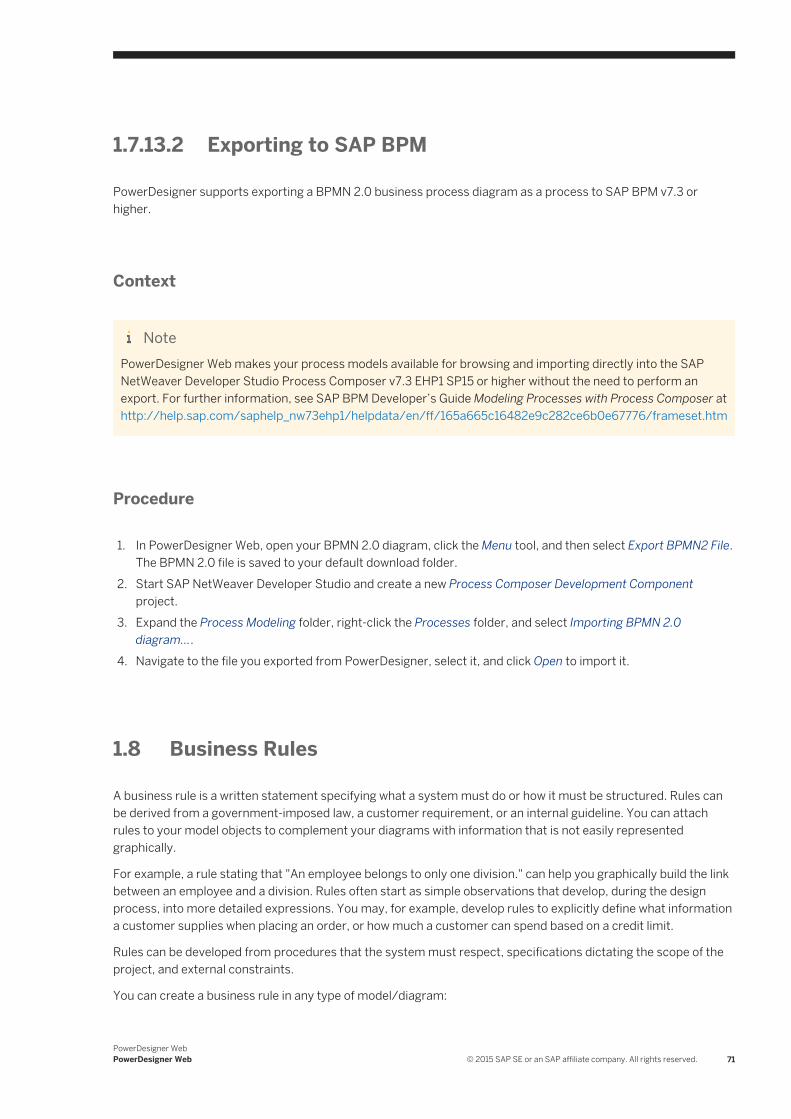
1.7.13.2 Exporting to SAP BPM
PowerDesigner supports exporting a BPMN 2.0 business process diagram as a process to SAP BPM v7.3 or higher.
Context
NotePowerDesigner Web makes your process models available for browsing and importing directly into the SAP NetWeaver Developer Studio Process Composer v7.3 EHP1 SP15 or higher without the need to perform an export. For further information, see SAP BPM Developer’s Guide Modeling Processes with Process Composer at http://help.sap.com/saphelp_nw73ehp1/helpdata/en/ff/165a665c16482e9c282ce6b0e67776/frameset.htm
Procedure
1. In PowerDesigner Web, open your BPMN 2.0 diagram, click the Menu tool, and then select Export BPMN2 File. The BPMN 2.0 file is saved to your default download folder.
2. Start SAP NetWeaver Developer Studio and create a new Process Composer Development Component project.
3. Expand the Process Modeling folder, right-click the Processes folder, and select Importing BPMN 2.0 diagram....
4. Navigate to the file you exported from PowerDesigner, select it, and click Open to import it.
1.8 Business Rules
A business rule is a written statement specifying what a system must do or how it must be structured. Rules can be derived from a government-imposed law, a customer requirement, or an internal guideline. You can attach rules to your model objects to complement your diagrams with information that is not easily represented graphically.
For example, a rule stating that "An employee belongs to only one division." can help you graphically build the link between an employee and a division. Rules often start as simple observations that develop, during the design process, into more detailed expressions. You may, for example, develop rules to explicitly define what information a customer supplies when placing an order, or how much a customer can spend based on a credit limit.
Rules can be developed from procedures that the system must respect, specifications dictating the scope of the project, and external constraints.
You can create a business rule in any type of model/diagram:
PowerDesigner WebPowerDesigner Web © 2015 SAP SE or an SAP affiliate company. All rights reserved. 71
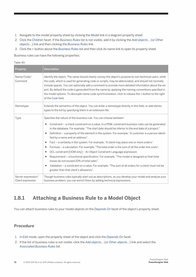
1. Navigate to the model property sheet by clicking the Model link in a diagram property sheet.2. Click the Children facet. If the Business Rules list is not visible, add it by clicking the Add objects... (or Other
objects...) link and then clicking the Business Rules link.3. Click the + button above the Business Rules list and then click its name link to open its property sheet.
Business rules can have the following properties:
Table 40:
Property Description
Name/Code/Comment
Identify the object. The name should clearly convey the object's purpose to non-technical users, while the code, which is used for generating code or scripts, may be abbreviated, and should not normally include spaces. You can optionally add a comment to provide more detailed information about the object. By default the code is generated from the name by applying the naming conventions specified in the model options. To decouple name-code synchronization, click to release the = button to the right of the Code field.
Stereotype Extends the semantics of the object. You can enter a stereotype directly in this field, or add stereotypes to the list by specifying them in an extension file.
Type Specifies the nature of the business rule. You can choose between:
● Constraint – a check constraint on a value. In a PDM, constraint business rules can be generated in the database. For example, "The start date should be inferior to the end date of a project."
● Definition – a property of the element in the system. For example; "A customer is a person identified by a name and an address".
● Fact – a certainty in the system. For example, "A client may place one or more orders".● Formula – a calculation. For example, "The total order is the sum of all the order line costs".● OCL constraint [OOM only] – An Object Constraint Language expression.● Requirement – a functional specification. For example, "The model is designed so that total
losses do not exceed 10% of total sales".● Validation – a constraint on a value. For example, "The sum of all orders for a client must not be
greater than that client's allowance".
Server expression/ Client expression
Though business rules typically start out as descriptions, as you develop your model and analyze your business problem, you can enrich them by adding technical expressions.
1.8.1 Attaching a Business Rule to a Model Object
You can attach business rules to your model objects on the Depends On facet of the object's property sheet.
Procedure
1. In Edit mode, open the property sheet of the object and click the Depends On facet.2. If the list of business rules is not visible, click the Add objects... (or Other objects...) link and select the
Associated Business Rules list.
72 © 2015 SAP SE or an SAP affiliate company. All rights reserved.PowerDesigner Web
PowerDesigner Web

3. Click the + tool at the top of the Associated Business Rules list and, in the dialog, navigate to the model containing the rule you want to link to in the left pane.
4. Select the rule that you want to link to and then click Add.The business rule is now attached to the object. You can navigate to it from the list on the object's Depends On facet. You can navigate from the rule to the object from the list of Attached Objects on the rules Impacts tab.
PowerDesigner WebPowerDesigner Web © 2015 SAP SE or an SAP affiliate company. All rights reserved. 73
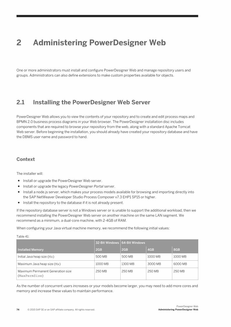
2 Administering PowerDesigner Web
One or more administrators must install and configure PowerDesigner Web and manage repository users and groups. Administrators can also define extensions to make custom properties available for objects.
2.1 Installing the PowerDesigner Web Server
PowerDesigner Web allows you to view the contents of your repository and to create and edit process maps and BPMN 2.0 business process diagrams in your Web browser. The PowerDesigner installation disc includes components that are required to browse your repository from the web, along with a standard Apache Tomcat Web server. Before beginning the installation, you should already have created your repository database and have the DBMS user name and password to hand.
Context
The installer will:
● Install or upgrade the PowerDesigner Web server.● Install or upgrade the legacy PowerDesigner Portal server.● Install a node.js server, which makes your process models available for browsing and importing directly into
the SAP NetWeaver Developer Studio Process Composer v7.3 EHP1 SP15 or higher.● Install the repository to the database if it is not already present.
If the repository database server is not a Windows server or is unable to support the additional workload, then we recommend installing the PowerDesigner Web server on another machine on the same LAN segment. We recommend as a minimum, a dual-core machine, with 2-4GB of RAM.
When configuring your Java virtual machine memory, we recommend the following initial values:
Table 41:
32-Bit Windows 64-Bit Windows
Installed Memory 2GB 2GB 4GB 8GB
Initial Java heap size (Ms) 500 MB 500 MB 1000 MB 1000 MB
Maximum Java heap size (Mx) 1000 MB 1300 MB 3000 MB 6000 MB
Maximum Permanent Generation size (MaxPermSize)
250 MB 250 MB 250 MB 250 MB
As the number of concurrent users increases or your models become larger, you may need to add more cores and memory and increase these values to maintain performance.
74 © 2015 SAP SE or an SAP affiliate company. All rights reserved.PowerDesigner Web
Administering PowerDesigner Web
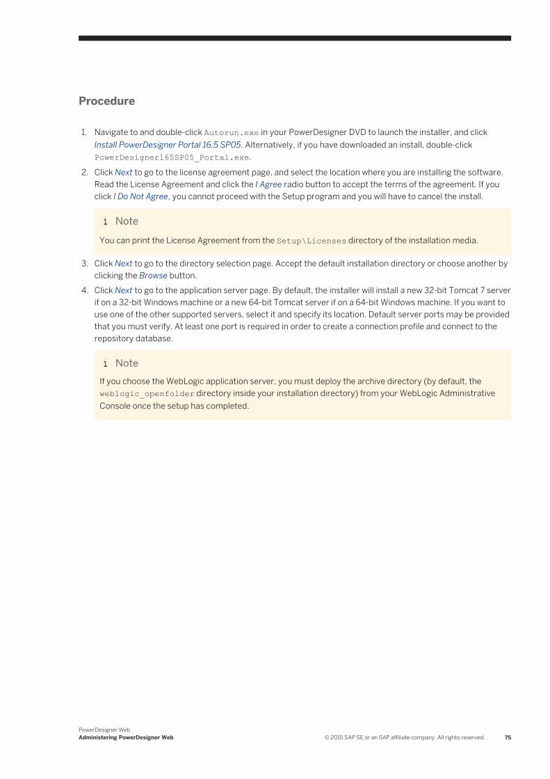
Procedure
1. Navigate to and double-click Autorun.exe in your PowerDesigner DVD to launch the installer, and click Install PowerDesigner Portal 16.5 SP05. Alternatively, if you have downloaded an install, double-click PowerDesigner165SP05_Portal.exe.
2. Click Next to go to the license agreement page, and select the location where you are installing the software. Read the License Agreement and click the I Agree radio button to accept the terms of the agreement. If you click I Do Not Agree, you cannot proceed with the Setup program and you will have to cancel the install.
NoteYou can print the License Agreement from the Setup\Licenses directory of the installation media.
3. Click Next to go to the directory selection page. Accept the default installation directory or choose another by clicking the Browse button.
4. Click Next to go to the application server page. By default, the installer will install a new 32-bit Tomcat 7 server if on a 32-bit Windows machine or a new 64-bit Tomcat server if on a 64-bit Windows machine. If you want to use one of the other supported servers, select it and specify its location. Default server ports may be provided that you must verify. At least one port is required in order to create a connection profile and connect to the repository database.
NoteIf you choose the WebLogic application server, you must deploy the archive directory (by default, the weblogic_openfolder directory inside your installation directory) from your WebLogic Administrative Console once the setup has completed.
PowerDesigner WebAdministering PowerDesigner Web © 2015 SAP SE or an SAP affiliate company. All rights reserved. 75
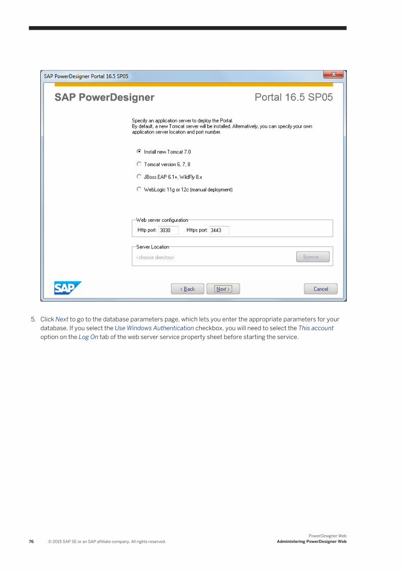
5. Click Next to go to the database parameters page, which lets you enter the appropriate parameters for your
database. If you select the Use Windows Authentication checkbox, you will need to select the This account option on the Log On tab of the web server service property sheet before starting the service.
76 © 2015 SAP SE or an SAP affiliate company. All rights reserved.PowerDesigner Web
Administering PowerDesigner Web
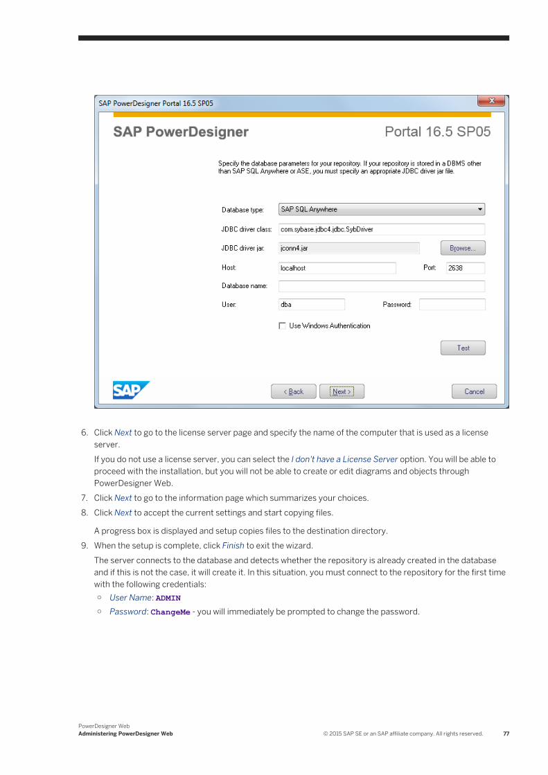
6. Click Next to go to the license server page and specify the name of the computer that is used as a license
server.If you do not use a license server, you can select the I don't have a License Server option. You will be able to proceed with the installation, but you will not be able to create or edit diagrams and objects through PowerDesigner Web.
7. Click Next to go to the information page which summarizes your choices.8. Click Next to accept the current settings and start copying files.
A progress box is displayed and setup copies files to the destination directory.9. When the setup is complete, click Finish to exit the wizard.
The server connects to the database and detects whether the repository is already created in the database and if this is not the case, it will create it. In this situation, you must connect to the repository for the first time with the following credentials:○ User Name: ADMIN○ Password: ChangeMe - you will immediately be prompted to change the password.
PowerDesigner WebAdministering PowerDesigner Web © 2015 SAP SE or an SAP affiliate company. All rights reserved. 77
2.2 Controlling Repository Access
The repository administrator is responsible for controlling access to the documents stored in the repository by creating users and groups and assigning them rights, permissions, and profiles. PowerDesigner can manage users itself and also supports LDAP and X.509 certificate-based authentication.
Context
Repository rights give users access to general repository features, while permissions give them access to particular locations in the repository. The following rights and permissions are available:
Table 42:
Rights (Entire Repository) Permissions (Per Folder or Item)
● Connect - Connect to the repository and view diagrams in PowerDesigner Web.
● Edit on Web - Create and edit diagrams in PowerDesigner Web.
● Edit Extensions on Web - Create and edit custom properties in PowerDesigner Web. Gives access to the Administration/Extensions tile.
● Freeze Versions - (only used with the desktop PowerDesigner client).
● Lock Versions - (only used with the desktop PowerDesigner client).
● Manage Branches - (only used with the desktop PowerDesigner client).
● Manage Configurations - (only used with the desktop PowerDesigner client).
● Manage All Documents - Perform any action on any document version. Implicitly includes Full permission on all repository documents.
● Manage Users - Create, modify, and delete repository users and groups, grant them rights, and add them to groups. Gives access to the Administration/Users and Groups tiles.
● Manage Repository - Create, upgrade, and delete the repository database. Gives access to the Administration/Settings tile.
● List - View the document or folder in the repository browser and in search results. Without this permission, the folder or document is hidden from the user.
● Read - Also open and compare documents.
● Submit - Also propose changes to the document for review by a user with Write permission.
● Write - Also review changes by other users and publish changes directly.
● Full - Also manage permissions granted to users and groups.
NoteAdministrators, who have implicit Full permission on all repository objects will only receive diagrams for review if they have been granted explicit Write permission on them.
Procedure
1. [recommended] Connect the repository to an SMTP server to enable the automatic sending of emails for passwords, changelist submissions, and other notifications (see Connecting to an SMTP Server for Notifications [page 98]).
78 © 2015 SAP SE or an SAP affiliate company. All rights reserved.PowerDesigner Web
Administering PowerDesigner Web
2. Determine how you will manage user authentication. You can choose one or more of:○ PowerDesigner-managed authentication - Specify an appropriate password policy (see Defining a
Password Policy [page 99]).○ LDAP authentication - Connect the repository to an LDAP server to manage user access (see Connecting
to an LDAP Server for User Authentication [page 94]).○ X.509 certificate-based single sign-on - [PowerDesigner Web-only] Configure the server appropriately
(see Enabling Single Sign-On for PowerDesigner Web [page 102]).
NoteLDAP or X.509 certificates are only used for authentication. Rights and permissions on repository folders and documents are controlled in the repository.
3. [optional] Create high-level functional groups (see Creating Repository Groups [page 82]) to organize users by type and assign appropriate rights to them to govern general actions that they can perform in the repository (see Granting Rights to Users and Groups [page 85]).For example:
Table 43:
Groups Rights
Administrators Connect, Manage All Documents, Manage Users, Manage Repository
Senior Architects [use the PowerDesigner desktop client] Connect, Edit on Web, Freeze Versions, Lock Versions, Manage Branches, Manage Configurations
Architects [use the PowerDesigner desktop client] Connect, Edit on Web, Freeze Versions, Lock Versions
Business Analysts Connect, Edit on Web
Process Owners Connect, Edit on Web, Edit Extensions on Web
Stakeholders Connect (to provide read-only access to PowerDesigner Web).
NoteThere is no requirement to create groups - you can assign rights and permissions to individual users - but we recommend that in all but the smallest deployments, you do create groups to simplify the process.
4. [optional] Apply profiles to your groups as necessary to filter the PowerDesigner interface to hide or render read-only types of models, objects, and properties, and to specify defaults for interface elements, options and preferences for different kinds of users . User profiles are developed and deployed only using the PowerDesigner desktop client but are applied to both the desktop client and PowerDesigner Web (see Core Features Guide > Administering PowerDesigner > Customizing the PowerDesigner Interface > Using Profiles to Control the PowerDesigner Interface).
5. Create an appropriate folder structure in the repository (see The Repository [page 8]) to enable you to group documents by project or in any other appropriate way, and to simplify the granting of permissions.In this example, we imagine the following simple folder structure in which processes are organized at a high-level by line of business:○ Library○ Process Map○ Process Diagrams
PowerDesigner WebAdministering PowerDesigner Web © 2015 SAP SE or an SAP affiliate company. All rights reserved. 79
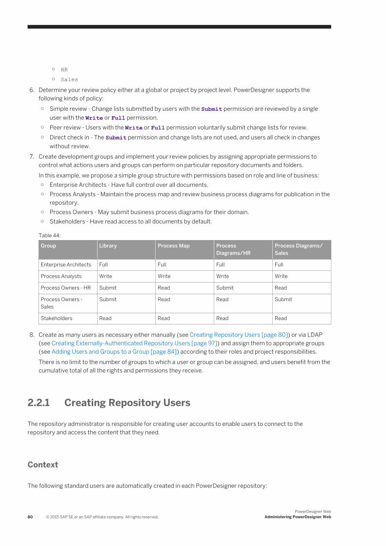
○ HR○ Sales
6. Determine your review policy either at a global or project by project level. PowerDesigner supports the following kinds of policy:○ Simple review - Change lists submitted by users with the Submit permission are reviewed by a single
user with the Write or Full permission.○ Peer review - Users with the Write or Full permission voluntarily submit change lists for review.○ Direct check in - The Submit permission and change lists are not used, and users all check in changes
without review.7. Create development groups and implement your review policies by assigning appropriate permissions to
control what actions users and groups can perform on particular repository documents and folders.In this example, we propose a simple group structure with permissions based on role and line of business:○ Enterprise Architects - Have full control over all documents.○ Process Analysts - Maintain the process map and review business process diagrams for publication in the
repository.○ Process Owners - May submit business process diagrams for their domain.○ Stakeholders - Have read access to all documents by default.
Table 44:
Group Library Process Map Process Diagrams/HR
Process Diagrams/Sales
Enterprise Architects Full Full Full Full
Process Analysts Write Write Write Write
Process Owners - HR Submit Read Submit Read
Process Owners - Sales
Submit Read Read Submit
Stakeholders Read Read Read Read
8. Create as many users as necessary either manually (see Creating Repository Users [page 80]) or via LDAP (see Creating Externally-Authenticated Repository Users [page 97]) and assign them to appropriate groups (see Adding Users and Groups to a Group [page 84]) according to their roles and project responsibilities.There is no limit to the number of groups to which a user or group can be assigned, and users benefit from the cumulative total of all the rights and permissions they receive.
2.2.1 Creating Repository Users
The repository administrator is responsible for creating user accounts to enable users to connect to the repository and access the content that they need.
Context
The following standard users are automatically created in each PowerDesigner repository:
80 © 2015 SAP SE or an SAP affiliate company. All rights reserved.PowerDesigner Web
Administering PowerDesigner Web
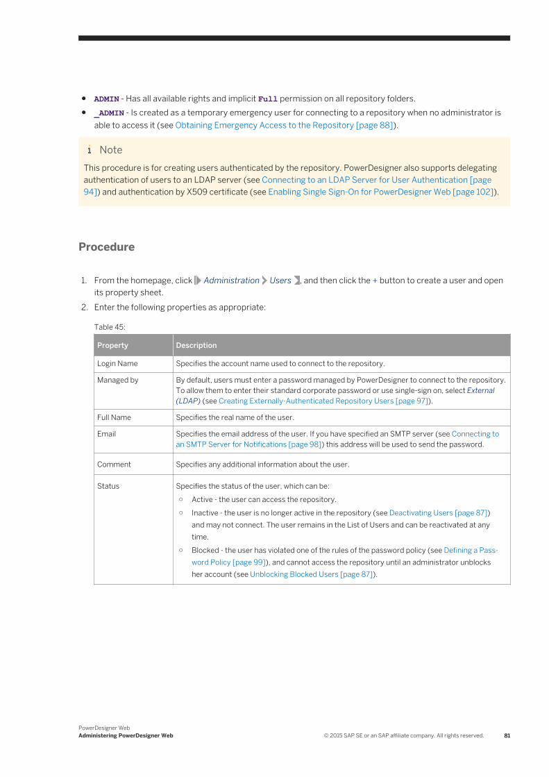
● ADMIN - Has all available rights and implicit Full permission on all repository folders.● _ADMIN - Is created as a temporary emergency user for connecting to a repository when no administrator is
able to access it (see Obtaining Emergency Access to the Repository [page 88]).
NoteThis procedure is for creating users authenticated by the repository. PowerDesigner also supports delegating authentication of users to an LDAP server (see Connecting to an LDAP Server for User Authentication [page 94]) and authentication by X509 certificate (see Enabling Single Sign-On for PowerDesigner Web [page 102]).
Procedure
1. From the homepage, click Administration Users , and then click the + button to create a user and open its property sheet.
2. Enter the following properties as appropriate:
Table 45:
Property Description
Login Name Specifies the account name used to connect to the repository.
Managed by By default, users must enter a password managed by PowerDesigner to connect to the repository. To allow them to enter their standard corporate password or use single-sign on, select External (LDAP) (see Creating Externally-Authenticated Repository Users [page 97]).
Full Name Specifies the real name of the user.
Email Specifies the email address of the user. If you have specified an SMTP server (see Connecting to an SMTP Server for Notifications [page 98]) this address will be used to send the password.
Comment Specifies any additional information about the user.
Status Specifies the status of the user, which can be:○ Active - the user can access the repository.○ Inactive - the user is no longer active in the repository (see Deactivating Users [page 87])
and may not connect. The user remains in the List of Users and can be reactivated at any time.
○ Blocked - the user has violated one of the rules of the password policy (see Defining a Password Policy [page 99]), and cannot access the repository until an administrator unblocks her account (see Unblocking Blocked Users [page 87]).
PowerDesigner WebAdministering PowerDesigner Web © 2015 SAP SE or an SAP affiliate company. All rights reserved. 81
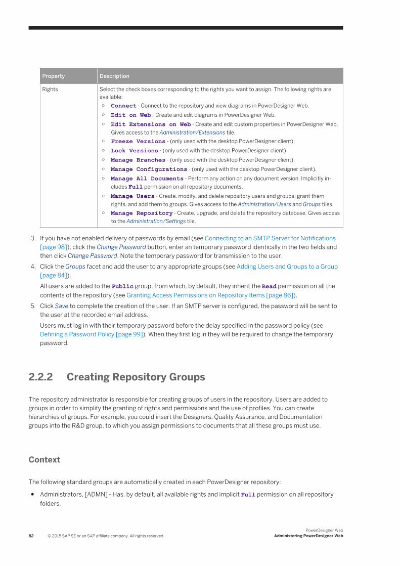
Property Description
Rights Select the check boxes corresponding to the rights you want to assign. The following rights are available:○ Connect - Connect to the repository and view diagrams in PowerDesigner Web.○ Edit on Web - Create and edit diagrams in PowerDesigner Web.○ Edit Extensions on Web - Create and edit custom properties in PowerDesigner Web.
Gives access to the Administration/Extensions tile.○ Freeze Versions - (only used with the desktop PowerDesigner client).○ Lock Versions - (only used with the desktop PowerDesigner client).○ Manage Branches - (only used with the desktop PowerDesigner client).○ Manage Configurations - (only used with the desktop PowerDesigner client).○ Manage All Documents - Perform any action on any document version. Implicitly in
cludes Full permission on all repository documents.○ Manage Users - Create, modify, and delete repository users and groups, grant them
rights, and add them to groups. Gives access to the Administration/Users and Groups tiles.○ Manage Repository - Create, upgrade, and delete the repository database. Gives access
to the Administration/Settings tile.
3. If you have not enabled delivery of passwords by email (see Connecting to an SMTP Server for Notifications [page 98]), click the Change Password button, enter an temporary password identically in the two fields and then click Change Password. Note the temporary password for transmission to the user.
4. Click the Groups facet and add the user to any appropriate groups (see Adding Users and Groups to a Group [page 84]).All users are added to the Public group, from which, by default, they inherit the Read permission on all the contents of the repository (see Granting Access Permissions on Repository Items [page 86]).
5. Click Save to complete the creation of the user. If an SMTP server is configured, the password will be sent to the user at the recorded email address.Users must log in with their temporary password before the delay specified in the password policy (see Defining a Password Policy [page 99]). When they first log in they will be required to change the temporary password.
2.2.2 Creating Repository Groups
The repository administrator is responsible for creating groups of users in the repository. Users are added to groups in order to simplify the granting of rights and permissions and the use of profiles. You can create hierarchies of groups. For example, you could insert the Designers, Quality Assurance, and Documentation groups into the R&D group, to which you assign permissions to documents that all these groups must use.
Context
The following standard groups are automatically created in each PowerDesigner repository:
● Administrators, [ADMN] - Has, by default, all available rights and implicit Full permission on all repository folders.
82 © 2015 SAP SE or an SAP affiliate company. All rights reserved.PowerDesigner Web
Administering PowerDesigner Web
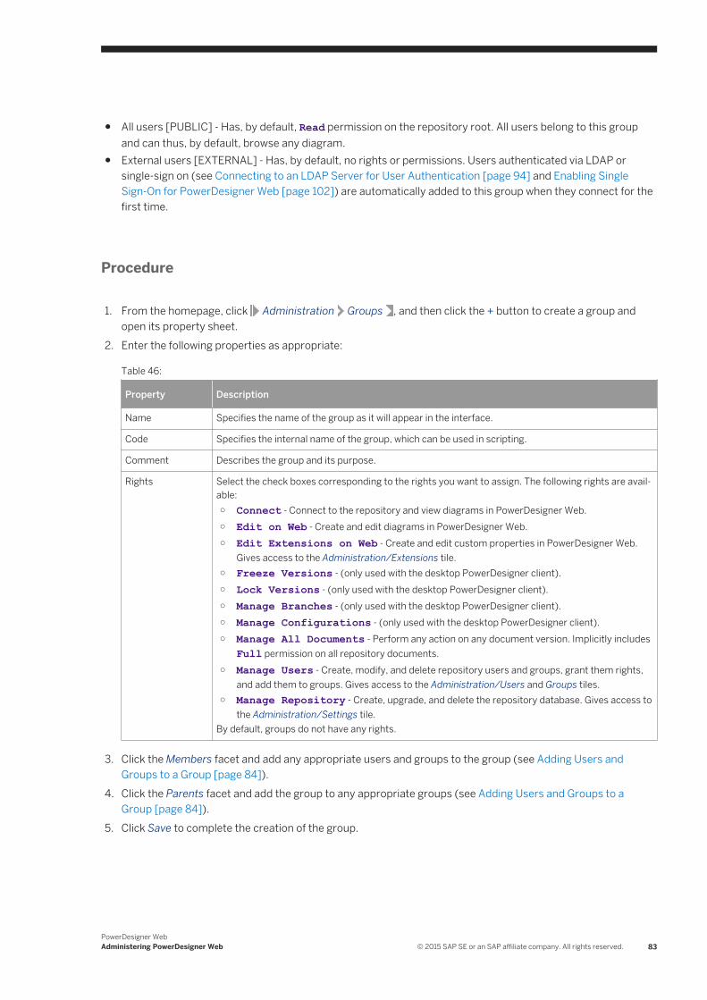
● All users [PUBLIC] - Has, by default, Read permission on the repository root. All users belong to this group and can thus, by default, browse any diagram.
● External users [EXTERNAL] - Has, by default, no rights or permissions. Users authenticated via LDAP or single-sign on (see Connecting to an LDAP Server for User Authentication [page 94] and Enabling Single Sign-On for PowerDesigner Web [page 102]) are automatically added to this group when they connect for the first time.
Procedure
1. From the homepage, click Administration Groups , and then click the + button to create a group and open its property sheet.
2. Enter the following properties as appropriate:
Table 46:
Property Description
Name Specifies the name of the group as it will appear in the interface.
Code Specifies the internal name of the group, which can be used in scripting.
Comment Describes the group and its purpose.
Rights Select the check boxes corresponding to the rights you want to assign. The following rights are available:○ Connect - Connect to the repository and view diagrams in PowerDesigner Web.○ Edit on Web - Create and edit diagrams in PowerDesigner Web.○ Edit Extensions on Web - Create and edit custom properties in PowerDesigner Web.
Gives access to the Administration/Extensions tile.○ Freeze Versions - (only used with the desktop PowerDesigner client).○ Lock Versions - (only used with the desktop PowerDesigner client).○ Manage Branches - (only used with the desktop PowerDesigner client).○ Manage Configurations - (only used with the desktop PowerDesigner client).○ Manage All Documents - Perform any action on any document version. Implicitly includes
Full permission on all repository documents.○ Manage Users - Create, modify, and delete repository users and groups, grant them rights,
and add them to groups. Gives access to the Administration/Users and Groups tiles.○ Manage Repository - Create, upgrade, and delete the repository database. Gives access to
the Administration/Settings tile.By default, groups do not have any rights.
3. Click the Members facet and add any appropriate users and groups to the group (see Adding Users and Groups to a Group [page 84]).
4. Click the Parents facet and add the group to any appropriate groups (see Adding Users and Groups to a Group [page 84]).
5. Click Save to complete the creation of the group.
PowerDesigner WebAdministering PowerDesigner Web © 2015 SAP SE or an SAP affiliate company. All rights reserved. 83
2.2.2.1 Adding Users and Groups to a Group
You can add users and groups as members of a group from either the user or the group property sheet.
Context
There are three ways to add members to a group:
● To add a user to a group from the user's property sheet, click the Groups facet, which lists the groups to which the user belongs. Click the + tool to open a list of groups, select one or more, and then click OK to add the user to them.
● To add a group to a parent group from the child group's property sheet, click the Parents facet, which lists the groups to which the group belongs. Click the + tool to open a list of groups, select one or more, and then click OK to add the group to them.
● To add a user or group to a group from the parent group's property sheet, click the Members facet, which lists the users and groups which are members of the group. Click the Add tool to open a list of users and groups, select one or more, and then click OK to add them to the group.
2.2.2.2 Deleting a Group
When you delete a group from the repository you do not delete the members (either users or groups) of the group.
Procedure
1. From the homepage, click Administration Groups .2. Select a group in the list and click the Delete tool. The group is removed from the list, and:
○ Any document permissions granted to the group are revoked.○ Any members of the group lose whatever rights or permissions they had inherited from the group.○ The group is removed from membership of any groups to which it belonged.
3. Click Save to save your changes.
84 © 2015 SAP SE or an SAP affiliate company. All rights reserved.PowerDesigner Web
Administering PowerDesigner Web
2.2.3 Granting Rights to Users and Groups
A new user has only the Connect right assigned by default and belongs only to the PUBLIC group. The repository administrator can grant additional rights to the user either directly or by adding her to other groups.
Context
NoteThe rights a user or group receive when they become members of a group (see Adding Users and Groups to a Group [page 84]) are cumulative. For example, a user with the Manage Branches right will not lose this right when he becomes a member of a group that has only the Freeze Versions and Lock Versions rights.
User rights are associated with document permissions (see Granting Access Permissions on Repository Items [page 86]) to define the actions a user can effectively perform on a document.
Procedure
1. From the homepage, click Administration Users (or Administration Groups ), and click the appropriate user or group in the list to open its property sheet.
2. Select the check boxes corresponding to the rights you want to assign. The following rights are available:○ Connect - Connect to the repository and view diagrams in PowerDesigner Web.○ Edit on Web - Create and edit diagrams in PowerDesigner Web.○ Edit Extensions on Web - Create and edit custom properties in PowerDesigner Web. Gives access to
the Administration/Extensions tile.○ Freeze Versions - (only used with the desktop PowerDesigner client).○ Lock Versions - (only used with the desktop PowerDesigner client).○ Manage Branches - (only used with the desktop PowerDesigner client).○ Manage Configurations - (only used with the desktop PowerDesigner client).○ Manage All Documents - Perform any action on any document version. Implicitly includes Full
permission on all repository documents.○ Manage Users - Create, modify, and delete repository users and groups, grant them rights, and add
them to groups. Gives access to the Administration/Users and Groups tiles.○ Manage Repository - Create, upgrade, and delete the repository database. Gives access to the
Administration/Settings tile.3. Click Save to save your changes.
PowerDesigner WebAdministering PowerDesigner Web © 2015 SAP SE or an SAP affiliate company. All rights reserved. 85

2.2.4 Granting Access Permissions on Repository Items
The repository administrator or a user with Full permission on a document or folder can grant permissions on it. Permissions can be granted on the repository root, folders, and models, but not on individual model diagrams or objects.
Context
A user wanting to browse and edit documents in the repository must have at least the following permissions:
● Browsing - Read permission. When you create a user, she is inserted into the Public group, which by default is granted Read permission on the repository root.
● Creating or editing a diagram - Submit on the target folder to propose a new diagram or edits to an existing diagram, or Write to publish them directly.
NoteObject permissions should be viewed in conjunction with the rights granted to users or groups (see Granting Rights to Users and Groups [page 85]).
Procedure
1. From the homepage, click Repository, navigate to the item, and click its Permissions facet.2. Click the + button to open a list of available users and groups, select one or more, and click OK to add them to
the list.3. For each user or group, select the permission you want to grant in the Granted Permission column. The
following permissions are available:○ List - View the document or folder in the repository browser and in search results. Without this
permission, the folder or document is hidden from the user.○ Read - Also open and compare documents.○ Submit - Also propose changes to the document for review by a user with Write permission.○ Write - Also review changes by other users and publish changes directly.○ Full - Also manage permissions granted to users and groups.
NoteAdministrators, who have implicit Full permission on all repository objects will only receive diagrams for review if they have been granted explicit Write permission on them.
The Effective Permissions column shows the highest level of permission that each user or group has either directly or via a group.
4. [optional] Click the Copy Permissions to All Children tool to propagate changes to the item's children.
86 © 2015 SAP SE or an SAP affiliate company. All rights reserved.PowerDesigner Web
Administering PowerDesigner Web
When you create a folder or check in a model or project, the permissions defined on its parent are propagated to it. However, subsequent changes made to the permissions for the parent are not applied to its children unless you click this tool. For example, if a you grant Write permission on the Major Project folder, to the Development Team 2 group, then they will not automatically be granted Write access on its contents.
2.2.5 Unblocking Blocked Users
The repository administrator or a user with the Manage Users right can unblock users blocked for password policy violations.
Procedure
1. From the homepage, click Administration Users and click the appropriate user in the list to open its property sheet.
2. Click the Change Password button. If you have not enabled delivery of passwords by email (see Connecting to an SMTP Server for Notifications [page 98]), enter a temporary password identically in the two fields and note it for transmission to the user.
3. Click the Change Password button. If an SMTP server is configured, the password will be sent to the user at the recorded email address.Users must log in with their temporary password before the delay specified in the password policy (see Defining a Password Policy [page 99]). When they first log in they will be required to change the temporary password.
2.2.6 Deactivating Users
The repository administrator or a user with the Manage Users right can deactivate users. An inactive user cannot connect to the repository, but the information about his checkins and other repository actions remains available to other users.
Context
CautionA user cannot deactivate himself, even if he has the Manage Users right.
PowerDesigner WebAdministering PowerDesigner Web © 2015 SAP SE or an SAP affiliate company. All rights reserved. 87
Procedure
1. From the homepage, click Administration Users , and click the Edit tool.2. Locate the user in the list and then select its checkbox in the Deactivated User column.
The user remains in the list but may no longer connect to the repository. If an inactive user is later reactivated he will have lost all previous rights, permissions, and group memberships, and will begin with only the Connect right.
2.2.7 Obtaining Emergency Access to the Repository
In the event that no administrator is able to log in to a running repository, you can create an emergency administrator account to regain access.
Procedure
1. If the repository proxy is not already in use in your environment, install it on the repository server or a nearby machine for which you are an administrator (see Installation Guide > Installing the Repository Proxy).
2. Launch the Repository Proxy Configuration utility (pdproxyconf16.exe).
NoteOn a Windows 7 machine, you must open the utility by right-clicking its icon or menu item and selecting Run as administrator.
3. If an instance is not already available for the repository in question, create one, specifying the appropriate data source, user name, password, and port to connect to the repository database.
4. Select the appropriate instance and click the Create Emergency User button to open the Emergency Password dialog, and then select Show password to see an automatically generated password, for use with the special _ADMIN account.
5. Navigate to the PowerDesigner Web homepage, enter _ADMIN as the login name and the generated password in the Password field, and click OK.
NoteIf you do not access the repository within 15 minutes, you must repeat the procedure to generate a new temporary password.
6. Reset the administrator's password or create a new administrator account as appropriate (see Creating Repository Users [page 80]).
7. Return to the homepage, click the _ADMIN user next to the menu tool and select Log Out to disconnect the emergency user from the repository. The emergency user is deleted after disconnection.
88 © 2015 SAP SE or an SAP affiliate company. All rights reserved.PowerDesigner Web
Administering PowerDesigner Web
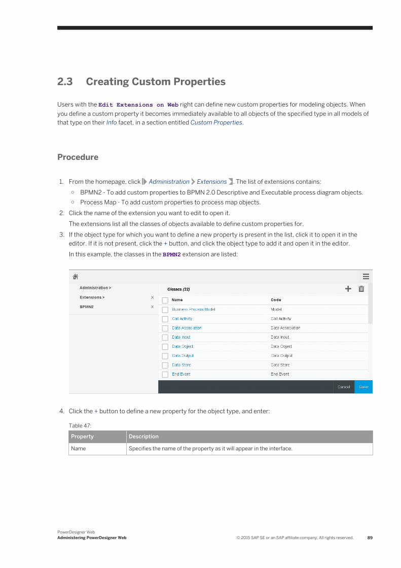
2.3 Creating Custom Properties
Users with the Edit Extensions on Web right can define new custom properties for modeling objects. When you define a custom property it becomes immediately available to all objects of the specified type in all models of that type on their Info facet, in a section entitled Custom Properties.
Procedure
1. From the homepage, click Administration Extensions . The list of extensions contains:○ BPMN2 - To add custom properties to BPMN 2.0 Descriptive and Executable process diagram objects.○ Process Map - To add custom properties to process map objects.
2. Click the name of the extension you want to edit to open it.The extensions list all the classes of objects available to define custom properties for.
3. If the object type for which you want to define a new property is present in the list, click it to open it in the editor. If it is not present, click the + button, and click the object type to add it and open it in the editor.In this example, the classes in the BPMN2 extension are listed:
4. Click the + button to define a new property for the object type, and enter:
Table 47:
Property Description
Name Specifies the name of the property as it will appear in the interface.
PowerDesigner WebAdministering PowerDesigner Web © 2015 SAP SE or an SAP affiliate company. All rights reserved. 89
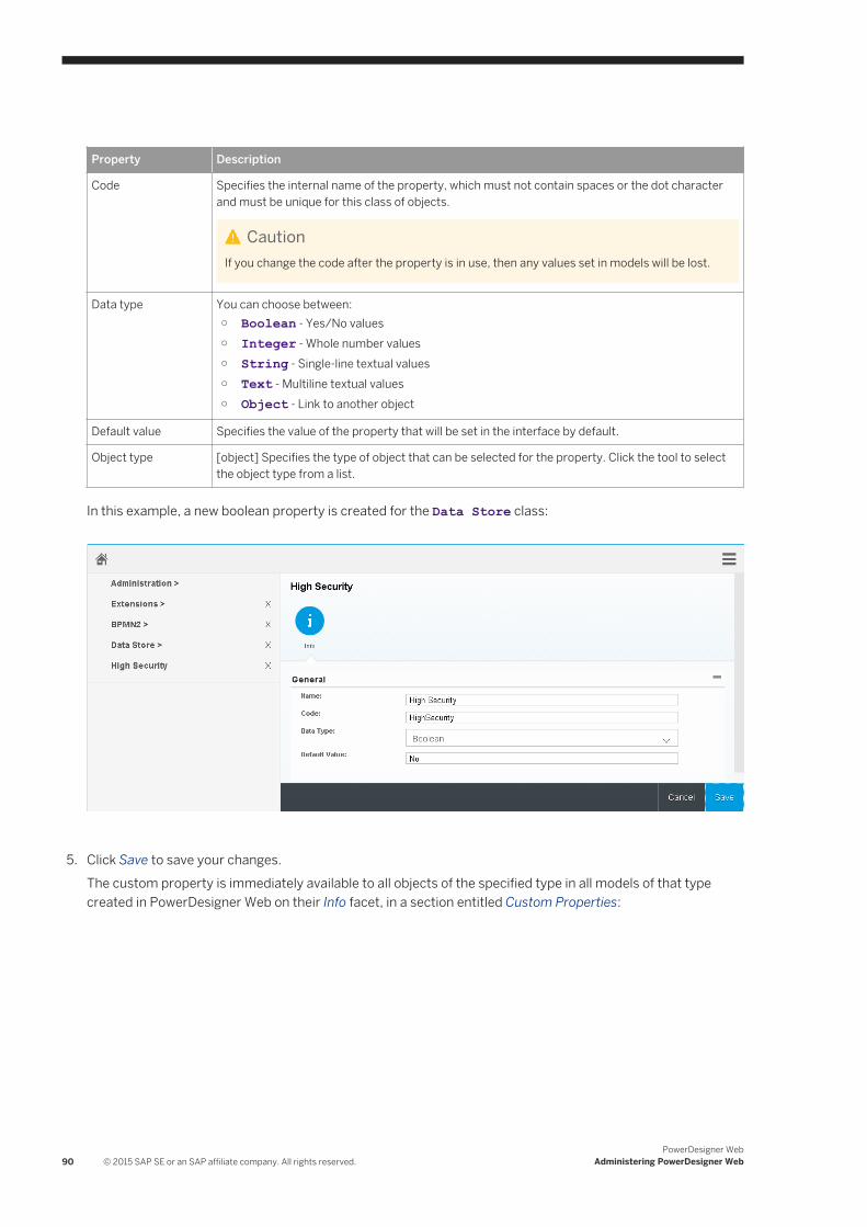
Property Description
Code Specifies the internal name of the property, which must not contain spaces or the dot character and must be unique for this class of objects.
CautionIf you change the code after the property is in use, then any values set in models will be lost.
Data type You can choose between:○ Boolean - Yes/No values○ Integer - Whole number values○ String - Single-line textual values○ Text - Multiline textual values○ Object - Link to another object
Default value Specifies the value of the property that will be set in the interface by default.
Object type [object] Specifies the type of object that can be selected for the property. Click the tool to select the object type from a list.
In this example, a new boolean property is created for the Data Store class:
5. Click Save to save your changes.The custom property is immediately available to all objects of the specified type in all models of that type created in PowerDesigner Web on their Info facet, in a section entitled Custom Properties:
90 © 2015 SAP SE or an SAP affiliate company. All rights reserved.PowerDesigner Web
Administering PowerDesigner Web
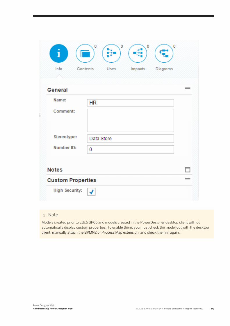
NoteModels created prior to v16.5 SP05 and models created in the PowerDesigner desktop client will not automatically display custom properties. To enable them, you must check the model out with the desktop client, manually attach the BPMN2 or Process Map extension, and check them in again.
PowerDesigner WebAdministering PowerDesigner Web © 2015 SAP SE or an SAP affiliate company. All rights reserved. 91
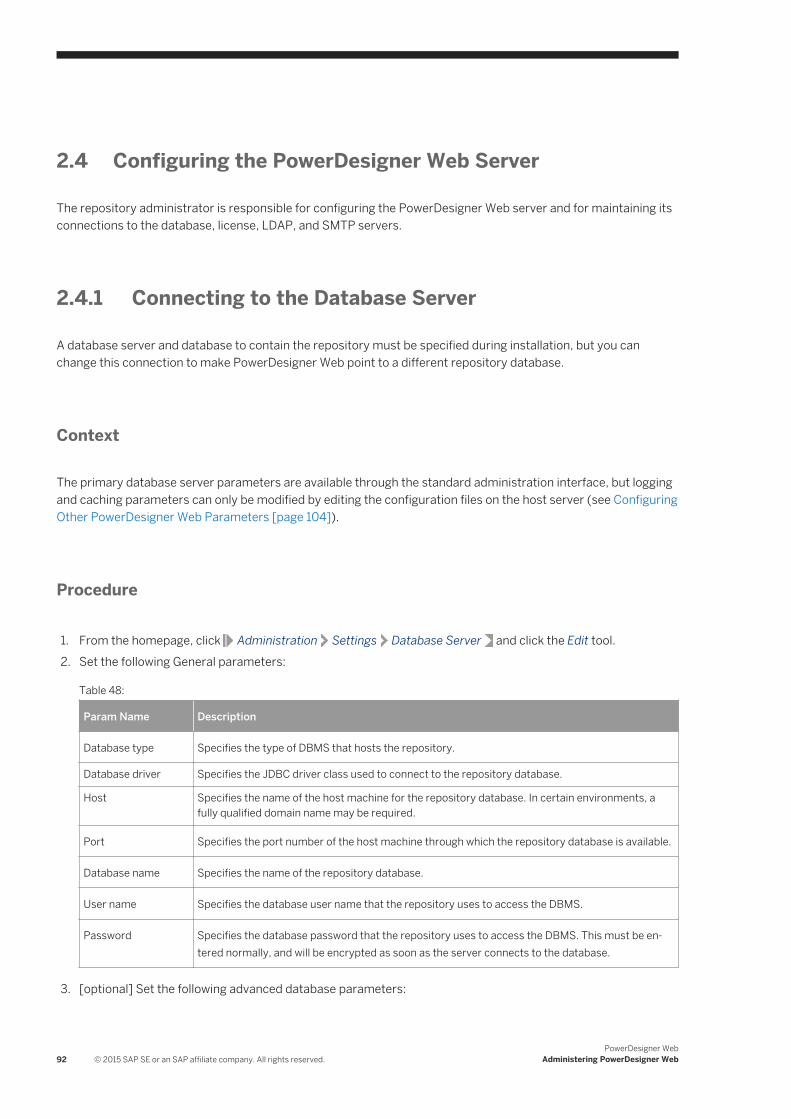
2.4 Configuring the PowerDesigner Web Server
The repository administrator is responsible for configuring the PowerDesigner Web server and for maintaining its connections to the database, license, LDAP, and SMTP servers.
2.4.1 Connecting to the Database Server
A database server and database to contain the repository must be specified during installation, but you can change this connection to make PowerDesigner Web point to a different repository database.
Context
The primary database server parameters are available through the standard administration interface, but logging and caching parameters can only be modified by editing the configuration files on the host server (see Configuring Other PowerDesigner Web Parameters [page 104]).
Procedure
1. From the homepage, click Administration Settings Database Server and click the Edit tool.2. Set the following General parameters:
Table 48:
Param Name Description
Database type Specifies the type of DBMS that hosts the repository.
Database driver Specifies the JDBC driver class used to connect to the repository database.
Host Specifies the name of the host machine for the repository database. In certain environments, a fully qualified domain name may be required.
Port Specifies the port number of the host machine through which the repository database is available.
Database name Specifies the name of the repository database.
User name Specifies the database user name that the repository uses to access the DBMS.
Password Specifies the database password that the repository uses to access the DBMS. This must be entered normally, and will be encrypted as soon as the server connects to the database.
3. [optional] Set the following advanced database parameters:
92 © 2015 SAP SE or an SAP affiliate company. All rights reserved.PowerDesigner Web
Administering PowerDesigner Web
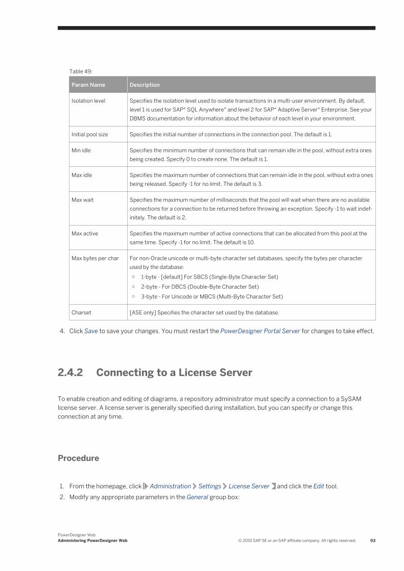
Table 49:
Param Name Description
Isolation level Specifies the isolation level used to isolate transactions in a multi-user environment. By default, level 1 is used for SAP® SQL Anywhere® and level 2 for SAP® Adaptive Server® Enterprise. See your DBMS documentation for information about the behavior of each level in your environment.
Initial pool size Specifies the initial number of connections in the connection pool. The default is 1.
Min idle Specifies the minimum number of connections that can remain idle in the pool, without extra ones being created. Specify 0 to create none. The default is 1.
Max idle Specifies the maximum number of connections that can remain idle in the pool, without extra ones being released. Specify -1 for no limit. The default is 3.
Max wait Specifies the maximum number of milliseconds that the pool will wait when there are no available connections for a connection to be returned before throwing an exception. Specify -1 to wait indefinitely. The default is 2.
Max active Specifies the maximum number of active connections that can be allocated from this pool at the same time. Specify -1 for no limit. The default is 10.
Max bytes per char For non-Oracle unicode or multi-byte character set databases, specify the bytes per character used by the database:○ 1-byte - [default] For SBCS (Single-Byte Character Set)○ 2-byte - For DBCS (Double-Byte Character Set)○ 3-byte - For Unicode or MBCS (Multi-Byte Character Set)
Charset [ASE only] Specifies the character set used by the database.
4. Click Save to save your changes. You must restart the PowerDesigner Portal Server for changes to take effect.
2.4.2 Connecting to a License Server
To enable creation and editing of diagrams, a repository administrator must specify a connection to a SySAM license server. A license server is generally specified during installation, but you can specify or change this connection at any time.
Procedure
1. From the homepage, click Administration Settings License Server and click the Edit tool.2. Modify any appropriate parameters in the General group box:
PowerDesigner WebAdministering PowerDesigner Web © 2015 SAP SE or an SAP affiliate company. All rights reserved. 93
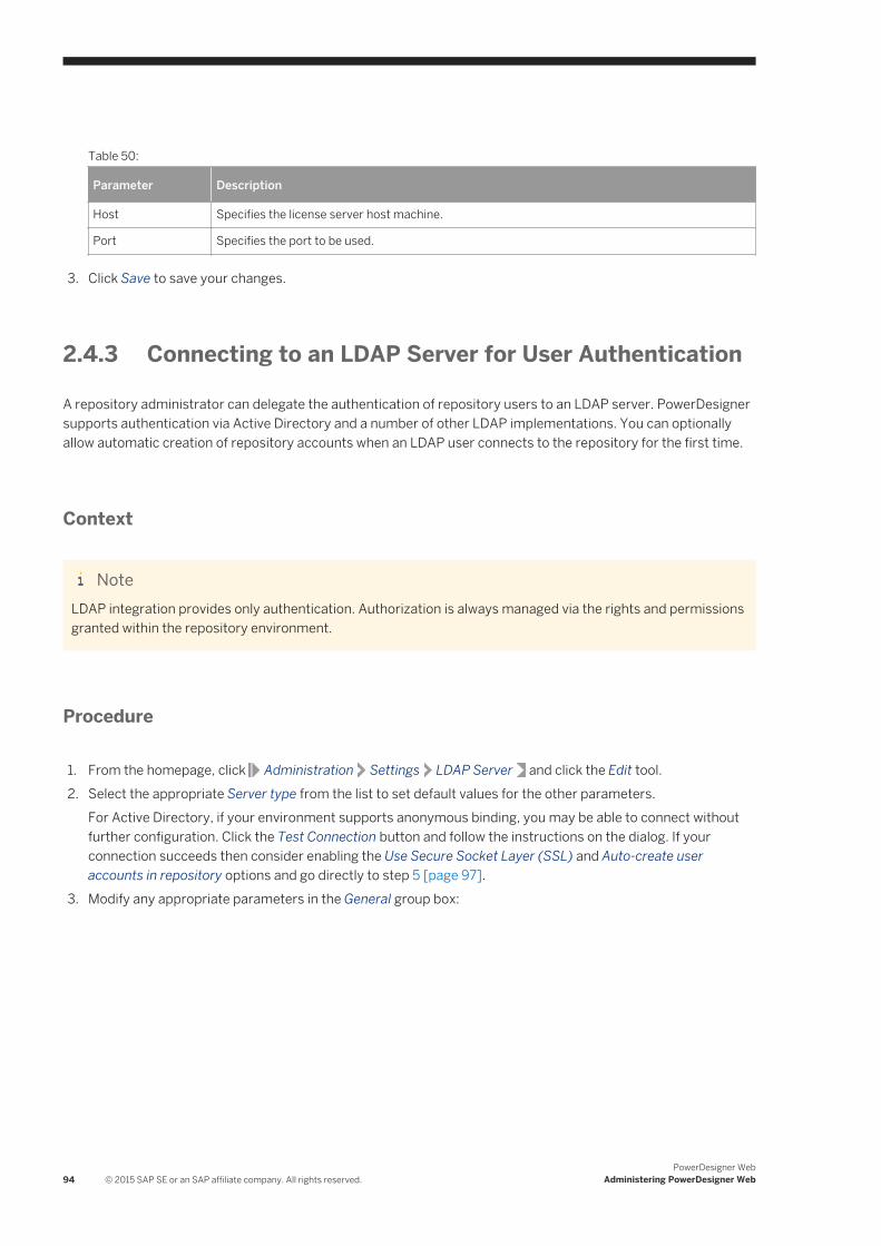
Table 50:
Parameter Description
Host Specifies the license server host machine.
Port Specifies the port to be used.
3. Click Save to save your changes.
2.4.3 Connecting to an LDAP Server for User Authentication
A repository administrator can delegate the authentication of repository users to an LDAP server. PowerDesigner supports authentication via Active Directory and a number of other LDAP implementations. You can optionally allow automatic creation of repository accounts when an LDAP user connects to the repository for the first time.
Context
NoteLDAP integration provides only authentication. Authorization is always managed via the rights and permissions granted within the repository environment.
Procedure
1. From the homepage, click Administration Settings LDAP Server and click the Edit tool.2. Select the appropriate Server type from the list to set default values for the other parameters.
For Active Directory, if your environment supports anonymous binding, you may be able to connect without further configuration. Click the Test Connection button and follow the instructions on the dialog. If your connection succeeds then consider enabling the Use Secure Socket Layer (SSL) and Auto-create user accounts in repository options and go directly to step 5 [page 97].
3. Modify any appropriate parameters in the General group box:
94 © 2015 SAP SE or an SAP affiliate company. All rights reserved.PowerDesigner Web
Administering PowerDesigner Web
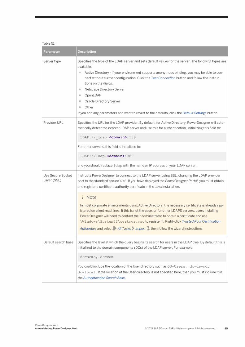
Table 51:
Parameter Description
Server type Specifies the type of the LDAP server and sets default values for the server. The following types are available:○ Active Directory - if your environment supports anonymous binding, you may be able to con
nect without further configuration. Click the Test Connection button and follow the instructions on the dialog.
○ Netscape Directory Server○ OpenLDAP○ Oracle Directory Server○ Other
If you edit any parameters and want to revert to the defaults, click the Default Settings button.
Provider URL Specifies the URL for the LDAP provider. By default, for Active Directory, PowerDesigner will automatically detect the nearest LDAP server and use this for authentication, initializing this field to:
LDAP://_ldap.<domain>:389
For other servers, this field is initialized to:
LDAP://ldap.<domain>:389
and you should replace ldap with the name or IP address of your LDAP server.
Use Secure Socket Layer (SSL)
Instructs PowerDesigner to connect to the LDAP server using SSL, changing the LDAP provider port to the standard secure 636. If you have deployed the PowerDesigner Portal, you must obtain and register a certificate authority certificate in the Java installation.
NoteIn most corporate environments using Active Directory, the necessary certificate is already registered on client machines. If this is not the case, or for other LDAPS servers, users installing PowerDesigner will need to contact their administrator to obtain a certificate and use \Windows\System32\certmgr.msc to register it. Right-click Trusted Root Certification
Authorities and select All Tasks Import , then follow the wizard instructions.
Default search base Specifies the level at which the query begins its search for users in the LDAP tree. By default this is initialized to the domain components (DCs) of the LDAP server. For example:
dc=acme, dc=com
You could include the location of the User directory such as OU=Users, dc=devpd, dc=local . If the location of the User directory is not specified here, then you must include it in the Authentication Search Base.
PowerDesigner WebAdministering PowerDesigner Web © 2015 SAP SE or an SAP affiliate company. All rights reserved. 95
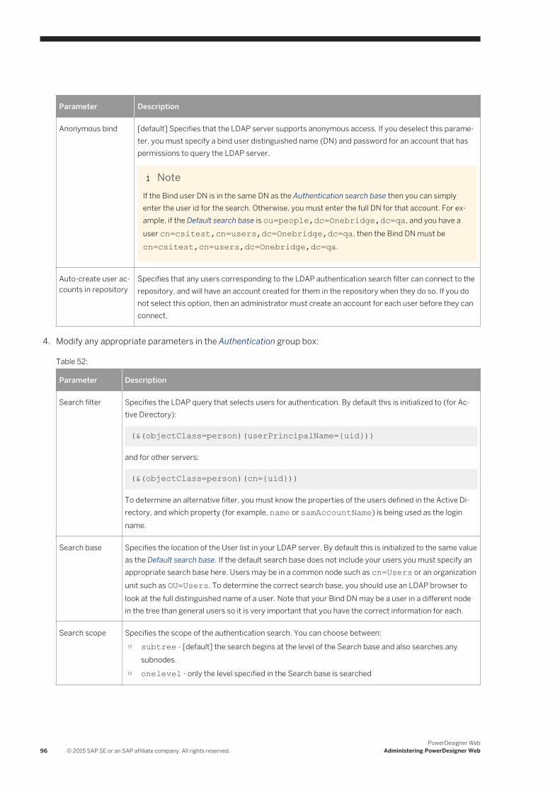
Parameter Description
Anonymous bind [default] Specifies that the LDAP server supports anonymous access. If you deselect this parameter, you must specify a bind user distinguished name (DN) and password for an account that has permissions to query the LDAP server.
NoteIf the Bind user DN is in the same DN as the Authentication search base then you can simply enter the user id for the search. Otherwise, you must enter the full DN for that account. For example, if the Default search base is ou=people,dc=Onebridge,dc=qa, and you have a user cn=csitest,cn=users,dc=Onebridge,dc=qa, then the Bind DN must be cn=csitest,cn=users,dc=Onebridge,dc=qa.
Auto-create user accounts in repository
Specifies that any users corresponding to the LDAP authentication search filter can connect to the repository, and will have an account created for them in the repository when they do so. If you do not select this option, then an administrator must create an account for each user before they can connect.
4. Modify any appropriate parameters in the Authentication group box:
Table 52:
Parameter Description
Search filter Specifies the LDAP query that selects users for authentication. By default this is initialized to (for Active Directory):
(&(objectClass=person)(userPrincipalName={uid}))
and for other servers:
(&(objectClass=person)(cn={uid}))
To determine an alternative filter, you must know the properties of the users defined in the Active Directory, and which property (for example, name or samAccountName) is being used as the login name.
Search base Specifies the location of the User list in your LDAP server. By default this is initialized to the same value as the Default search base. If the default search base does not include your users you must specify an appropriate search base here. Users may be in a common node such as cn=Users or an organization unit such as OU=Users. To determine the correct search base, you should use an LDAP browser to look at the full distinguished name of a user. Note that your Bind DN may be a user in a different node in the tree than general users so it is very important that you have the correct information for each.
Search scope Specifies the scope of the authentication search. You can choose between:
○ subtree - [default] the search begins at the level of the Search base and also searches any subnodes.
○ onelevel - only the level specified in the Search base is searched
96 © 2015 SAP SE or an SAP affiliate company. All rights reserved.PowerDesigner Web
Administering PowerDesigner Web
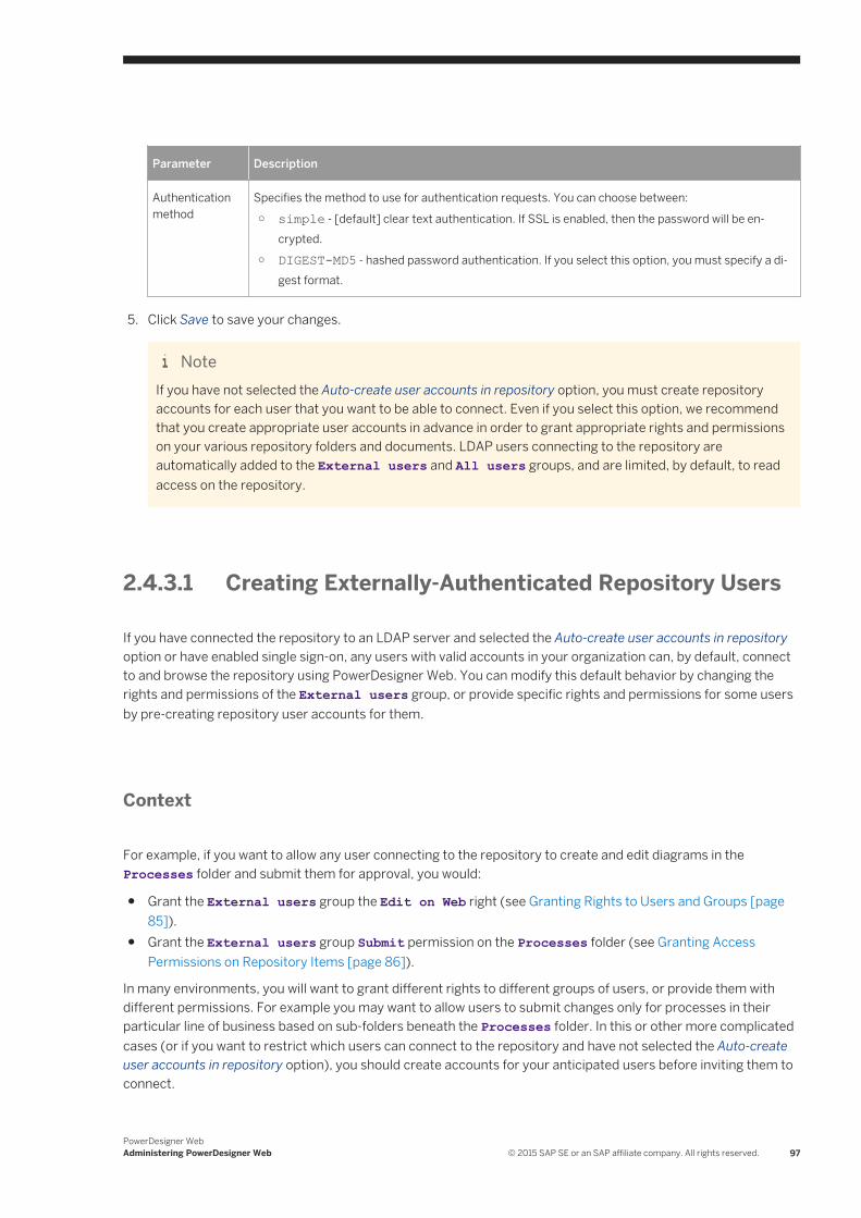
Parameter Description
Authentication method
Specifies the method to use for authentication requests. You can choose between:
○ simple - [default] clear text authentication. If SSL is enabled, then the password will be encrypted.
○ DIGEST-MD5 - hashed password authentication. If you select this option, you must specify a digest format.
5. Click Save to save your changes.
NoteIf you have not selected the Auto-create user accounts in repository option, you must create repository accounts for each user that you want to be able to connect. Even if you select this option, we recommend that you create appropriate user accounts in advance in order to grant appropriate rights and permissions on your various repository folders and documents. LDAP users connecting to the repository are automatically added to the External users and All users groups, and are limited, by default, to read access on the repository.
2.4.3.1 Creating Externally-Authenticated Repository Users
If you have connected the repository to an LDAP server and selected the Auto-create user accounts in repository option or have enabled single sign-on, any users with valid accounts in your organization can, by default, connect to and browse the repository using PowerDesigner Web. You can modify this default behavior by changing the rights and permissions of the External users group, or provide specific rights and permissions for some users by pre-creating repository user accounts for them.
Context
For example, if you want to allow any user connecting to the repository to create and edit diagrams in the Processes folder and submit them for approval, you would:
● Grant the External users group the Edit on Web right (see Granting Rights to Users and Groups [page 85]).
● Grant the External users group Submit permission on the Processes folder (see Granting Access Permissions on Repository Items [page 86]).
In many environments, you will want to grant different rights to different groups of users, or provide them with different permissions. For example you may want to allow users to submit changes only for processes in their particular line of business based on sub-folders beneath the Processes folder. In this or other more complicated cases (or if you want to restrict which users can connect to the repository and have not selected the Auto-create user accounts in repository option), you should create accounts for your anticipated users before inviting them to connect.
PowerDesigner WebAdministering PowerDesigner Web © 2015 SAP SE or an SAP affiliate company. All rights reserved. 97
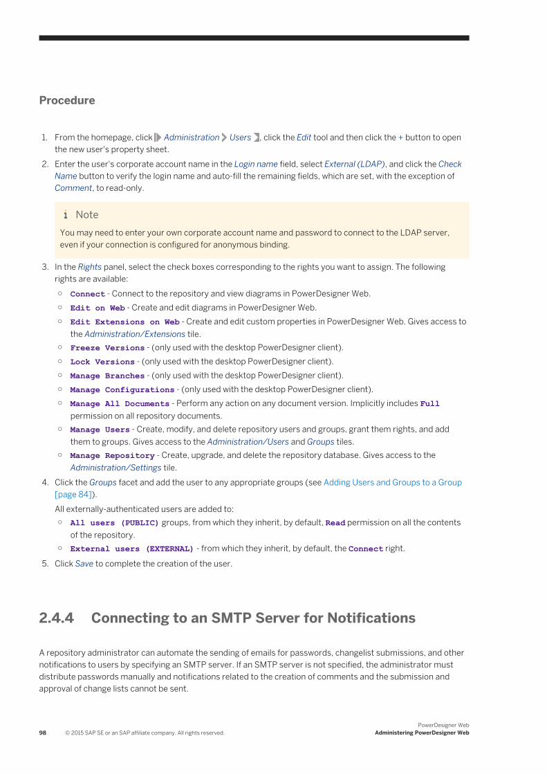
Procedure
1. From the homepage, click Administration Users , click the Edit tool and then click the + button to open the new user's property sheet.
2. Enter the user's corporate account name in the Login name field, select External (LDAP), and click the Check Name button to verify the login name and auto-fill the remaining fields, which are set, with the exception of Comment, to read-only.
NoteYou may need to enter your own corporate account name and password to connect to the LDAP server, even if your connection is configured for anonymous binding.
3. In the Rights panel, select the check boxes corresponding to the rights you want to assign. The following rights are available:○ Connect - Connect to the repository and view diagrams in PowerDesigner Web.○ Edit on Web - Create and edit diagrams in PowerDesigner Web.○ Edit Extensions on Web - Create and edit custom properties in PowerDesigner Web. Gives access to
the Administration/Extensions tile.○ Freeze Versions - (only used with the desktop PowerDesigner client).○ Lock Versions - (only used with the desktop PowerDesigner client).○ Manage Branches - (only used with the desktop PowerDesigner client).○ Manage Configurations - (only used with the desktop PowerDesigner client).○ Manage All Documents - Perform any action on any document version. Implicitly includes Full
permission on all repository documents.○ Manage Users - Create, modify, and delete repository users and groups, grant them rights, and add
them to groups. Gives access to the Administration/Users and Groups tiles.○ Manage Repository - Create, upgrade, and delete the repository database. Gives access to the
Administration/Settings tile.4. Click the Groups facet and add the user to any appropriate groups (see Adding Users and Groups to a Group
[page 84]).All externally-authenticated users are added to:○ All users (PUBLIC) groups, from which they inherit, by default, Read permission on all the contents
of the repository.○ External users (EXTERNAL) - from which they inherit, by default, the Connect right.
5. Click Save to complete the creation of the user.
2.4.4 Connecting to an SMTP Server for Notifications
A repository administrator can automate the sending of emails for passwords, changelist submissions, and other notifications to users by specifying an SMTP server. If an SMTP server is not specified, the administrator must distribute passwords manually and notifications related to the creation of comments and the submission and approval of change lists cannot be sent.
98 © 2015 SAP SE or an SAP affiliate company. All rights reserved.PowerDesigner Web
Administering PowerDesigner Web
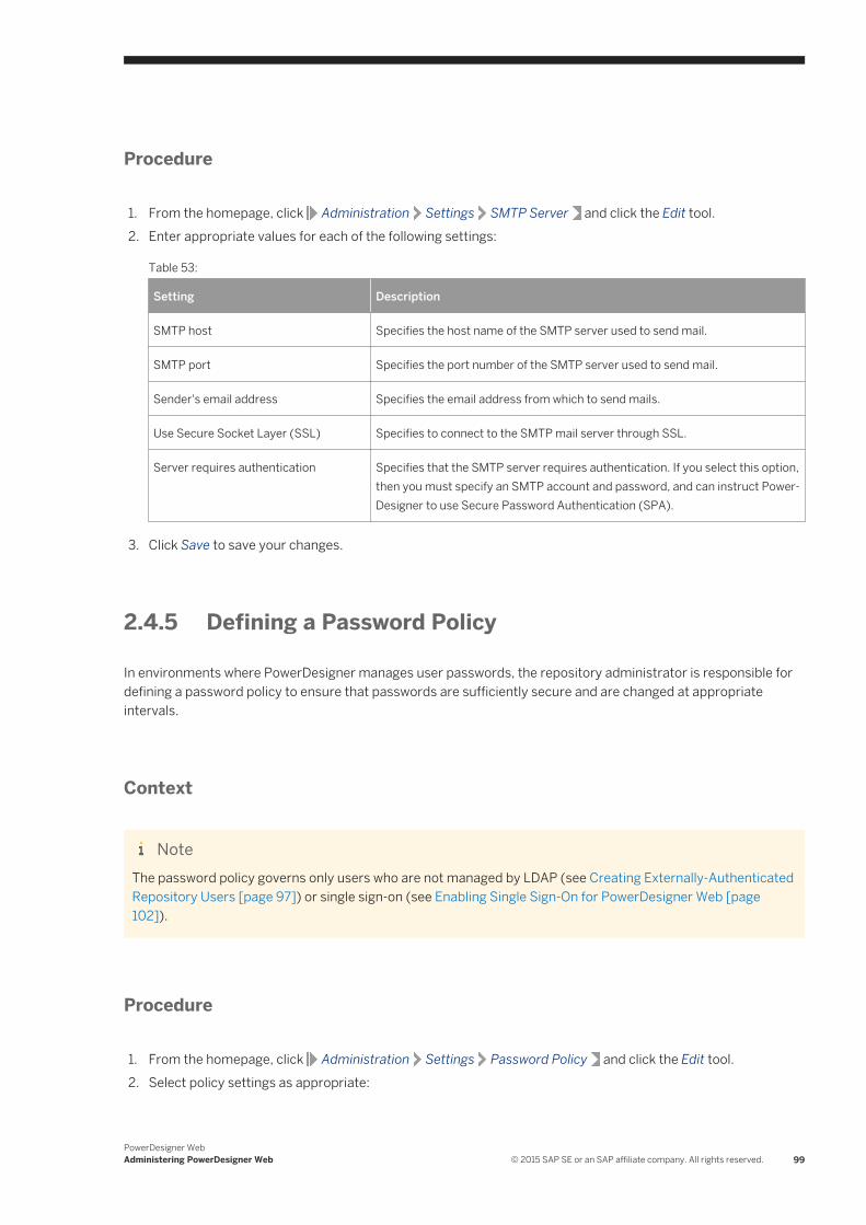
Procedure
1. From the homepage, click Administration Settings SMTP Server and click the Edit tool.2. Enter appropriate values for each of the following settings:
Table 53:
Setting Description
SMTP host Specifies the host name of the SMTP server used to send mail.
SMTP port Specifies the port number of the SMTP server used to send mail.
Sender's email address Specifies the email address from which to send mails.
Use Secure Socket Layer (SSL) Specifies to connect to the SMTP mail server through SSL.
Server requires authentication Specifies that the SMTP server requires authentication. If you select this option, then you must specify an SMTP account and password, and can instruct PowerDesigner to use Secure Password Authentication (SPA).
3. Click Save to save your changes.
2.4.5 Defining a Password Policy
In environments where PowerDesigner manages user passwords, the repository administrator is responsible for defining a password policy to ensure that passwords are sufficiently secure and are changed at appropriate intervals.
Context
NoteThe password policy governs only users who are not managed by LDAP (see Creating Externally-Authenticated Repository Users [page 97]) or single sign-on (see Enabling Single Sign-On for PowerDesigner Web [page 102]).
Procedure
1. From the homepage, click Administration Settings Password Policy and click the Edit tool.2. Select policy settings as appropriate:
PowerDesigner WebAdministering PowerDesigner Web © 2015 SAP SE or an SAP affiliate company. All rights reserved. 99
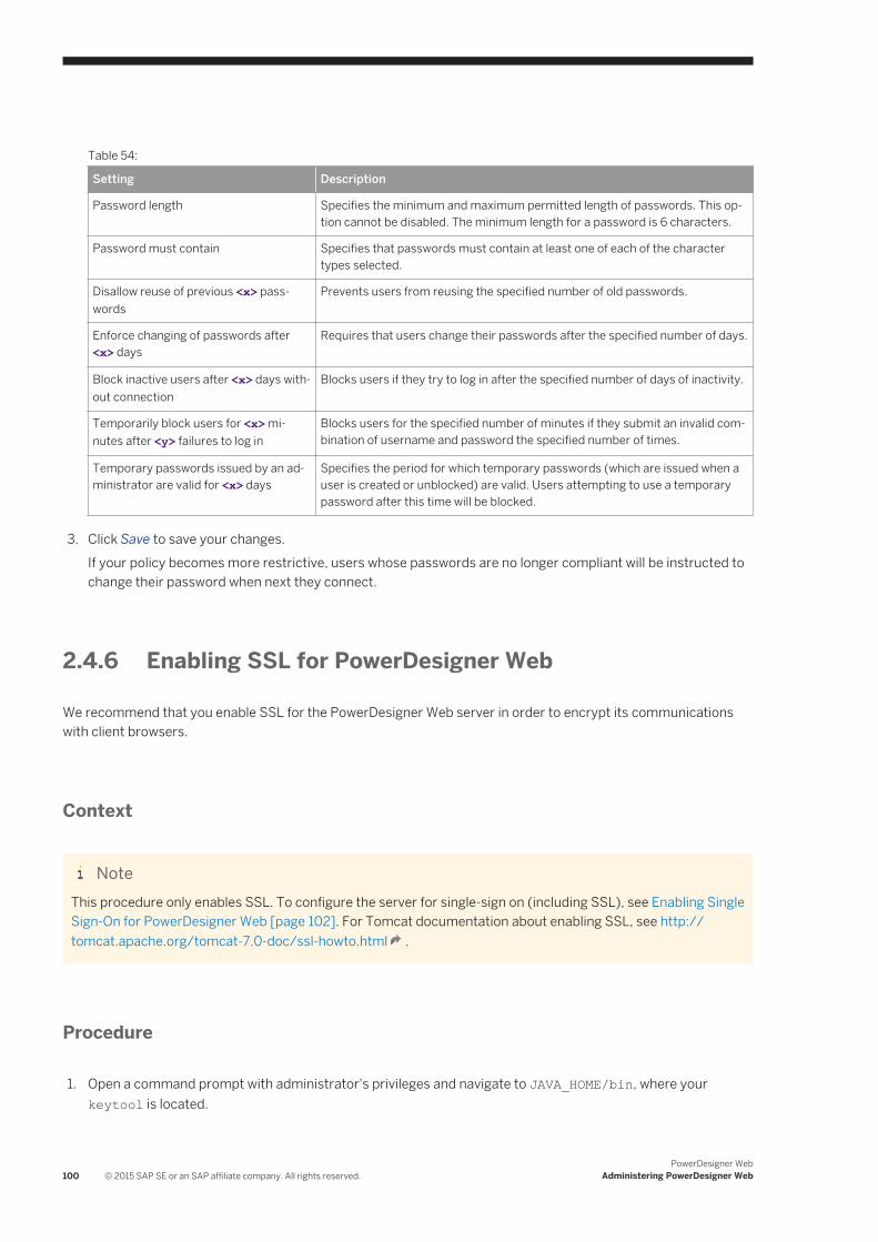
Table 54:
Setting Description
Password length Specifies the minimum and maximum permitted length of passwords. This option cannot be disabled. The minimum length for a password is 6 characters.
Password must contain Specifies that passwords must contain at least one of each of the character types selected.
Disallow reuse of previous <x> passwords
Prevents users from reusing the specified number of old passwords.
Enforce changing of passwords after <x> days
Requires that users change their passwords after the specified number of days.
Block inactive users after <x> days without connection
Blocks users if they try to log in after the specified number of days of inactivity.
Temporarily block users for <x> minutes after <y> failures to log in
Blocks users for the specified number of minutes if they submit an invalid combination of username and password the specified number of times.
Temporary passwords issued by an administrator are valid for <x> days
Specifies the period for which temporary passwords (which are issued when a user is created or unblocked) are valid. Users attempting to use a temporary password after this time will be blocked.
3. Click Save to save your changes.If your policy becomes more restrictive, users whose passwords are no longer compliant will be instructed to change their password when next they connect.
2.4.6 Enabling SSL for PowerDesigner Web
We recommend that you enable SSL for the PowerDesigner Web server in order to encrypt its communications with client browsers.
Context
NoteThis procedure only enables SSL. To configure the server for single-sign on (including SSL), see Enabling Single Sign-On for PowerDesigner Web [page 102]. For Tomcat documentation about enabling SSL, see http://tomcat.apache.org/tomcat-7.0-doc/ssl-howto.html .
Procedure
1. Open a command prompt with administrator's privileges and navigate to JAVA_HOME/bin, where your keytool is located.
100 © 2015 SAP SE or an SAP affiliate company. All rights reserved.PowerDesigner Web
Administering PowerDesigner Web
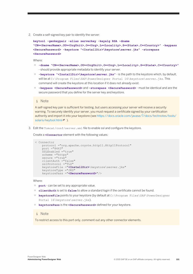
2. Create a self-signed key pair to identify the server:
keytool -genkeypair -alias serverkey -keyalg RSA -dname "CN=<ServerName>,OU=<OrgUnit>,O=<Org>,L=<Locality>,S=<State>,C=<Country>" -keypass <SecurePassword> -keystore "<InstallDir>\keystore\server.jks" -storepass <SecurePassword>
Where:○ -dname "CN=<ServerName>,OU=<OrgUnit>,O=<Org>,L=<Locality>,S=<State>,C=<Country>"
- should provide appropriate metadata to identify your server.○ -keystore "<InstallDir>\keystore\server.jks" - is the path to the keystore which, by default,
will be at C:\Program Files\SAP\PowerDesigner Portal 16\keystore\server.jks. This command will create the keystore at this location if it does not already exist.
○ -keypass <SecurePassword> and -storepass <SecurePassword> - must be identical and are the secure password that you define for the server key and keystore.
NoteA self-signed key pair is sufficient for testing, but users accessing your server will receive a security warning. To securely identify your server, you must request a certificate signed by your certification authority and import it into your keystore (see https://docs.oracle.com/javase/7/docs/technotes/tools/solaris/keytool.html ).
3. Edit the Tomcat/conf/server.xml file to enable ssl and configure the keystore.
Create a <Connector element with the following values:
< Connector protocol ="org.apache.coyote.http11.Http11Protocol" port ="8443" SSLEnabled ="true" scheme ="https" secure ="true" clientAuth ="false" sslProtocol ="TLS" keystoreFile ="<InstallDir>\keystore\server.jks" keystoreType ="JKS" keystorePass ="<SecurePassword>"/>
Where:○ port - can be set to any appropriate value.○ clientAuth is set to false to allow a standard login if the certificate cannot be found.○ keystoreFile points to your keystore (by default at C:\Program Files\SAP\PowerDesigner
Portal 16\keystore\server.jks).○ keystorePass is the <SecurePassword> defined for your keystore.
NoteTo restrict access to this port only, comment out any other connector elements.
PowerDesigner WebAdministering PowerDesigner Web © 2015 SAP SE or an SAP affiliate company. All rights reserved. 101
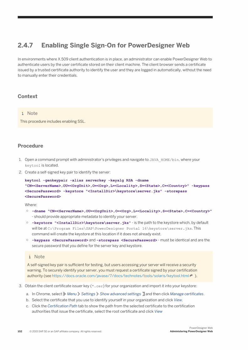
2.4.7 Enabling Single Sign-On for PowerDesigner Web
In environments where X.509 client authentication is in place, an administrator can enable PowerDesigner Web to authenticate users by the user certificate stored on their client machine. The client browser sends a certificate issued by a trusted certificate authority to identify the user and they are logged in automatically, without the need to manually enter their credentials.
Context
NoteThis procedure includes enabling SSL.
Procedure
1. Open a command prompt with administrator's privileges and navigate to JAVA_HOME/bin, where your keytool is located.
2. Create a self-signed key pair to identify the server:
keytool -genkeypair -alias serverkey -keyalg RSA -dname "CN=<ServerName>,OU=<OrgUnit>,O=<Org>,L=<Locality>,S=<State>,C=<Country>" -keypass <SecurePassword> -keystore "<InstallDir>\keystore\server.jks" -storepass <SecurePassword>
Where:○ -dname "CN=<ServerName>,OU=<OrgUnit>,O=<Org>,L=<Locality>,S=<State>,C=<Country>"
- should provide appropriate metadata to identify your server.○ -keystore "<InstallDir>\keystore\server.jks" - is the path to the keystore which, by default
will be at C:\Program Files\SAP\PowerDesigner Portal 16\keystore\server.jks. This command will create the keystore at this location if it does not already exist.
○ -keypass <SecurePassword> and -storepass <SecurePassword> - must be identical and are the secure password that you define for the server key and keystore.
NoteA self-signed key pair is sufficient for testing, but users accessing your server will receive a security warning. To securely identify your server, you must request a certificate signed by your certification authority (see https://docs.oracle.com/javase/7/docs/technotes/tools/solaris/keytool.html ).
3. Obtain the client certificate issuer key (*.cer) for your organization and import it into your keystore:
a. In Chrome, select Menu Settings Show advanced settings and then click Manage certificates.b. Select the certificate that you use to identify yourself in your organization and click View.c. Click the Certification Path tab to show the path from the selected certificate to the certification
authorities that issue the certificate, select the root certificate and click View
102 © 2015 SAP SE or an SAP affiliate company. All rights reserved.PowerDesigner Web
Administering PowerDesigner Web
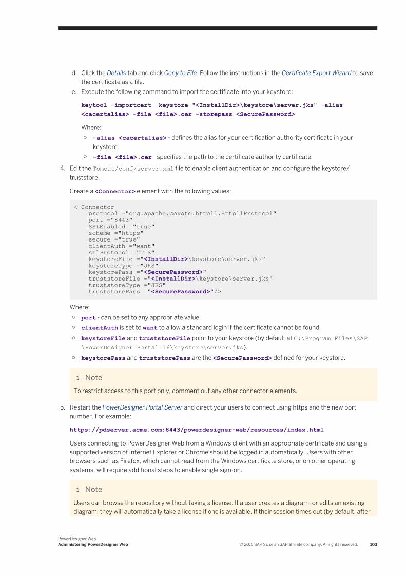
d. Click the Details tab and click Copy to File. Follow the instructions in the Certificate Export Wizard to save the certificate as a file.
e. Execute the following command to import the certificate into your keystore:
keytool -importcert -keystore "<InstallDir>\keystore\server.jks" -alias <cacertalias> -file <file>.cer -storepass <SecurePassword>
Where:○ -alias <cacertalias> - defines the alias for your certification authority certificate in your
keystore.○ -file <file>.cer - specifies the path to the certificate authority certificate.
4. Edit the Tomcat/conf/server.xml file to enable client authentication and configure the keystore/truststore.
Create a <Connector> element with the following values:
< Connector protocol ="org.apache.coyote.http11.Http11Protocol" port ="8443" SSLEnabled ="true" scheme ="https" secure ="true" clientAuth ="want" sslProtocol ="TLS" keystoreFile ="<InstallDir>\keystore\server.jks" keystoreType ="JKS" keystorePass ="<SecurePassword>" truststoreFile ="<InstallDir>\keystore\server.jks" truststoreType ="JKS" truststorePass ="<SecurePassword>"/>
Where:○ port - can be set to any appropriate value.○ clientAuth is set to want to allow a standard login if the certificate cannot be found.○ keystoreFile and truststoreFile point to your keystore (by default at C:\Program Files\SAP
\PowerDesigner Portal 16\keystore\server.jks).○ keystorePass and truststorePass are the <SecurePassword> defined for your keystore.
NoteTo restrict access to this port only, comment out any other connector elements.
5. Restart the PowerDesigner Portal Server and direct your users to connect using https and the new port number. For example:
https://pdserver.acme.com:8443/powerdesigner-web/resources/index.html
Users connecting to PowerDesigner Web from a Windows client with an appropriate certificate and using a supported version of Internet Explorer or Chrome should be logged in automatically. Users with other browsers such as Firefox, which cannot read from the Windows certificate store, or on other operating systems, will require additional steps to enable single sign-on.
NoteUsers can browse the repository without taking a license. If a user creates a diagram, or edits an existing diagram, they will automatically take a license if one is available. If their session times out (by default, after
PowerDesigner WebAdministering PowerDesigner Web © 2015 SAP SE or an SAP affiliate company. All rights reserved. 103
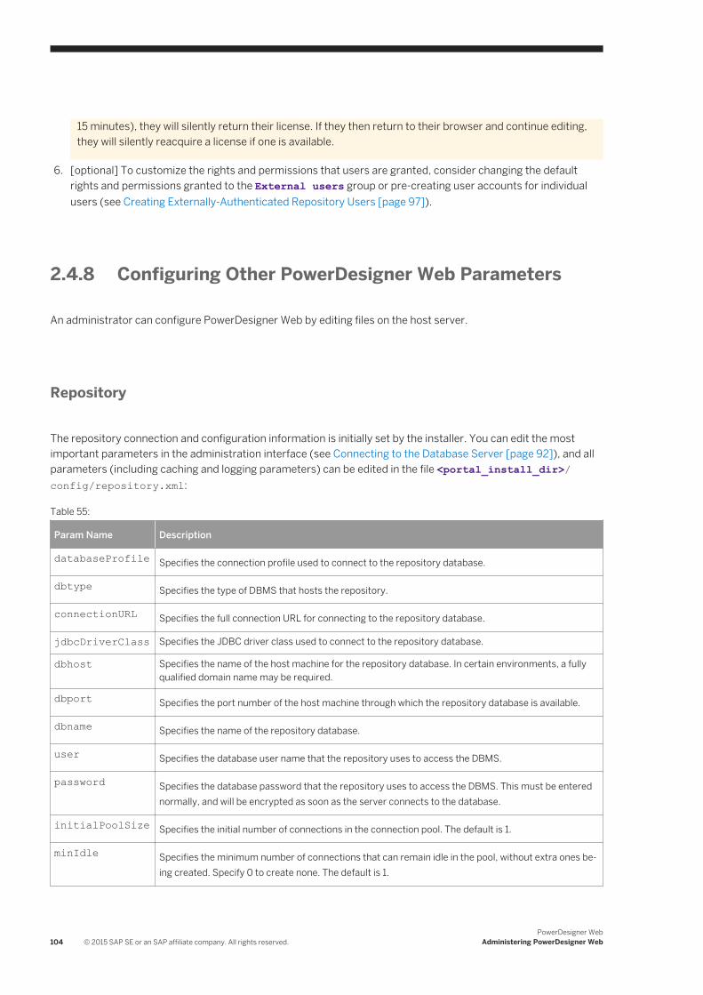
15 minutes), they will silently return their license. If they then return to their browser and continue editing, they will silently reacquire a license if one is available.
6. [optional] To customize the rights and permissions that users are granted, consider changing the default rights and permissions granted to the External users group or pre-creating user accounts for individual users (see Creating Externally-Authenticated Repository Users [page 97]).
2.4.8 Configuring Other PowerDesigner Web Parameters
An administrator can configure PowerDesigner Web by editing files on the host server.
Repository
The repository connection and configuration information is initially set by the installer. You can edit the most important parameters in the administration interface (see Connecting to the Database Server [page 92]), and all parameters (including caching and logging parameters) can be edited in the file <portal_install_dir>/config/repository.xml:
Table 55:
Param Name Description
databaseProfile Specifies the connection profile used to connect to the repository database.
dbtype Specifies the type of DBMS that hosts the repository.
connectionURL Specifies the full connection URL for connecting to the repository database.
jdbcDriverClass Specifies the JDBC driver class used to connect to the repository database.
dbhost Specifies the name of the host machine for the repository database. In certain environments, a fully qualified domain name may be required.
dbport Specifies the port number of the host machine through which the repository database is available.
dbname Specifies the name of the repository database.
user Specifies the database user name that the repository uses to access the DBMS.
password Specifies the database password that the repository uses to access the DBMS. This must be entered normally, and will be encrypted as soon as the server connects to the database.
initialPoolSize Specifies the initial number of connections in the connection pool. The default is 1.
minIdle Specifies the minimum number of connections that can remain idle in the pool, without extra ones being created. Specify 0 to create none. The default is 1.
104 © 2015 SAP SE or an SAP affiliate company. All rights reserved.PowerDesigner Web
Administering PowerDesigner Web
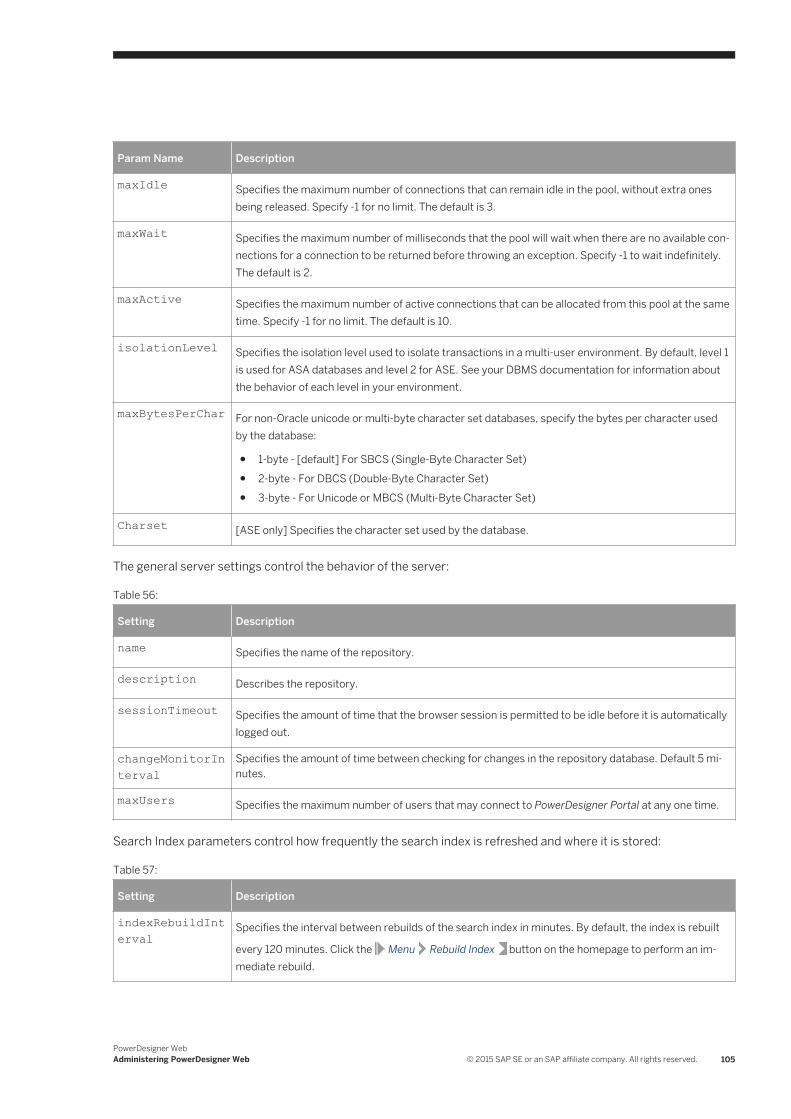
Param Name Description
maxIdle Specifies the maximum number of connections that can remain idle in the pool, without extra ones being released. Specify -1 for no limit. The default is 3.
maxWait Specifies the maximum number of milliseconds that the pool will wait when there are no available connections for a connection to be returned before throwing an exception. Specify -1 to wait indefinitely. The default is 2.
maxActive Specifies the maximum number of active connections that can be allocated from this pool at the same time. Specify -1 for no limit. The default is 10.
isolationLevel Specifies the isolation level used to isolate transactions in a multi-user environment. By default, level 1 is used for ASA databases and level 2 for ASE. See your DBMS documentation for information about the behavior of each level in your environment.
maxBytesPerChar For non-Oracle unicode or multi-byte character set databases, specify the bytes per character used by the database:
● 1-byte - [default] For SBCS (Single-Byte Character Set)● 2-byte - For DBCS (Double-Byte Character Set)● 3-byte - For Unicode or MBCS (Multi-Byte Character Set)
Charset [ASE only] Specifies the character set used by the database.
The general server settings control the behavior of the server:
Table 56:
Setting Description
name Specifies the name of the repository.
description Describes the repository.
sessionTimeout Specifies the amount of time that the browser session is permitted to be idle before it is automatically logged out.
changeMonitorInterval
Specifies the amount of time between checking for changes in the repository database. Default 5 minutes.
maxUsers Specifies the maximum number of users that may connect to PowerDesigner Portal at any one time.
Search Index parameters control how frequently the search index is refreshed and where it is stored:
Table 57:
Setting Description
indexRebuildInterval
Specifies the interval between rebuilds of the search index in minutes. By default, the index is rebuilt
every 120 minutes. Click the Menu Rebuild Index button on the homepage to perform an immediate rebuild.
PowerDesigner WebAdministering PowerDesigner Web © 2015 SAP SE or an SAP affiliate company. All rights reserved. 105
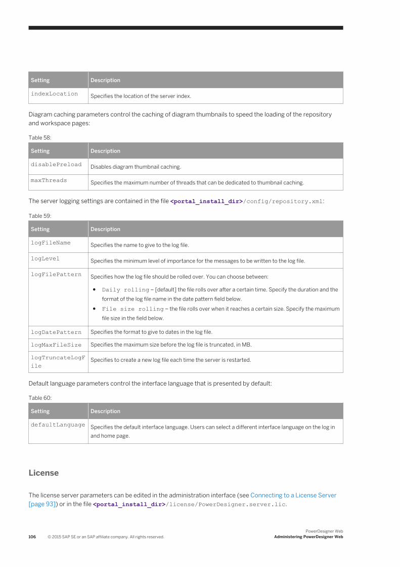
Setting Description
indexLocation Specifies the location of the server index.
Diagram caching parameters control the caching of diagram thumbnails to speed the loading of the repository and workspace pages:
Table 58:
Setting Description
disablePreload Disables diagram thumbnail caching.
maxThreads Specifies the maximum number of threads that can be dedicated to thumbnail caching.
The server logging settings are contained in the file <portal_install_dir>/config/repository.xml:
Table 59:
Setting Description
logFileName Specifies the name to give to the log file.
logLevel Specifies the minimum level of importance for the messages to be written to the log file.
logFilePattern Specifies how the log file should be rolled over. You can choose between:
● Daily rolling – [default] the file rolls over after a certain time. Specify the duration and the format of the log file name in the date pattern field below.
● File size rolling – the file rolls over when it reaches a certain size. Specify the maximum file size in the field below.
logDatePattern Specifies the format to give to dates in the log file.
logMaxFileSize Specifies the maximum size before the log file is truncated, in MB.
logTruncateLogFile
Specifies to create a new log file each time the server is restarted.
Default language parameters control the interface language that is presented by default:
Table 60:
Setting Description
defaultLanguage Specifies the default interface language. Users can select a different interface language on the log in and home page.
License
The license server parameters can be edited in the administration interface (see Connecting to a License Server [page 93]) or in the file <portal_install_dir>/license/PowerDesigner.server.lic.
106 © 2015 SAP SE or an SAP affiliate company. All rights reserved.PowerDesigner Web
Administering PowerDesigner Web

Client
The client information is contained in the file <portal_install_dir>/config/cmrclient.xml. The logging options are the same as for the server (see above).
PowerDesigner WebAdministering PowerDesigner Web © 2015 SAP SE or an SAP affiliate company. All rights reserved. 107
Important Disclaimers and Legal Information
Coding SamplesAny software coding and/or code lines / strings ("Code") included in this documentation are only examples and are not intended to be used in a productive system environment. The Code is only intended to better explain and visualize the syntax and phrasing rules of certain coding. SAP does not warrant the correctness and completeness of the Code given herein, and SAP shall not be liable for errors or damages caused by the usage of the Code, unless damages were caused by SAP intentionally or by SAP's gross negligence.
AccessibilityThe information contained in the SAP documentation represents SAP's current view of accessibility criteria as of the date of publication; it is in no way intended to be a binding guideline on how to ensure accessibility of software products. SAP in particular disclaims any liability in relation to this document. This disclaimer, however, does not apply in cases of wilful misconduct or gross negligence of SAP. Furthermore, this document does not result in any direct or indirect contractual obligations of SAP.
Gender-Neutral LanguageAs far as possible, SAP documentation is gender neutral. Depending on the context, the reader is addressed directly with "you", or a gender-neutral noun (such as "sales person" or "working days") is used. If when referring to members of both sexes, however, the third-person singular cannot be avoided or a gender-neutral noun does not exist, SAP reserves the right to use the masculine form of the noun and pronoun. This is to ensure that the documentation remains comprehensible.
Internet HyperlinksThe SAP documentation may contain hyperlinks to the Internet. These hyperlinks are intended to serve as a hint about where to find related information. SAP does not warrant the availability and correctness of this related information or the ability of this information to serve a particular purpose. SAP shall not be liable for any damages caused by the use of related information unless damages have been caused by SAP's gross negligence or willful misconduct. All links are categorized for transparency (see: http://help.sap.com/disclaimer).
108 © 2015 SAP SE or an SAP affiliate company. All rights reserved.PowerDesigner Web
Important Disclaimers and Legal Information

PowerDesigner WebImportant Disclaimers and Legal Information © 2015 SAP SE or an SAP affiliate company. All rights reserved. 109

www.sap.com/contactsap
© 2015 SAP SE or an SAP affiliate company. All rights reserved.No part of this publication may be reproduced or transmitted in any form or for any purpose without the express permission of SAP SE or an SAP affiliate company. The information contained herein may be changed without prior notice.Some software products marketed by SAP SE and its distributors contain proprietary software components of other software vendors. National product specifications may vary.These materials are provided by SAP SE or an SAP affiliate company for informational purposes only, without representation or warranty of any kind, and SAP or its affiliated companies shall not be liable for errors or omissions with respect to the materials. The only warranties for SAP or SAP affiliate company products and services are those that are set forth in the express warranty statements accompanying such products and services, if any. Nothing herein should be construed as constituting an additional warranty.SAP and other SAP products and services mentioned herein as well as their respective logos are trademarks or registered trademarks of SAP SE (or an SAP affiliate company) in Germany and other countries. All other product and service names mentioned are the trademarks of their respective companies.Please see http://www.sap.com/corporate-en/legal/copyright/index.epx for additional trademark information and notices.