Embed Size (px)
Citation preview


Index 1. Cold Checks - Part Nos. of Various Components of POWERCOM. 2. Engine Ratings 3. Front Panel Description- Display, Menu Selection Switches and Indicator Description 4. Connector Details – Description, Engine Interface Alternator Interface and Data Link Interface 5. Internal Interfaces - ECB – ACMD Harness connection details and LED Board – ACMD Harness connection details 6. Fault Codes and Troubleshooting in Powercom 7. Sensor Specifications of Powercom – Engine Speed sensor and Pressure Sensor 8. Calibration of Powercom through C-View 9. Factory Settings in Powercom 10. Wiring Diagram 11. Parameters to be logged on Hourly Basis
Commissioning report for POWERCOM:-
ESN: Model: Customer: OEM:
Name of commissioning Engineer: Name of OEM Engineer: Date of commissioning: PowerCom Serial no. :
1.0 COLD CHECKS
Parts List (Kindly confirm by actual Inspection)
Part number Superceded part number Part description
0319-6104 PowerCom complete assembly
0300-6085 PowerCom engine control board
0300-6086 AC Module board
0300-6087 DISPLAY CONTROL (MEMBRANE)
0300-6088 Display-Control (LED Board)
0402-0764-01 Isolator Vibration
504975 Three position key switch
3408561 3408560 Oil pressure sensor
3875360 Magnetic pick up
0193-0468 Coolant level sensor
3408345 Intake manifold temperature sensor (optional)
Adapter for Coolant Temp. Sensor 4053490
Adapter for IMT Sensor
3330601 Actuator, ETR Fuel control
4071944 Fuel Actuator Housing
3865346 Coolant Temp Sensor
4071851 From converter to ECP side
4071853 PowerCom to converter
4071852 From PowerCom to converter c
4071717 RS232 to RS485 converter
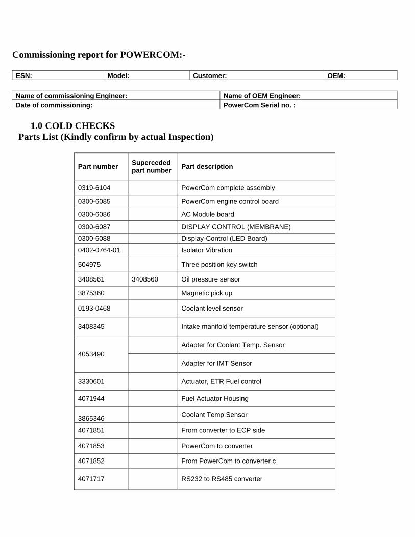
0338-4729 Cable between AC Module to engine control board
0338-4735 K6 harness
0338-4736 N14 Harness
0338-4737 V28 Harness
0338-4738 855 Harness 0338-4739 4105287
PT CT Harness Calibration CD
Current transformers 380 kVA
Current transformers 450 kVA
Current transformers 500 kVA 0315-1688-04 ( Qty-3)
Current transformers 625 kVA
Note: Part no. of ECPG engine harness and that of Powercom are different. Please check before installation.
2.0 POWERCOM engine ratings ENGINE MODEL KVA Rating KW Rating CT Ratio
VTA-28-G5 625 500 2000:5
KTA19G9 500 400 2000:5
KTA19G4 500 400 2000:5
NTA14G3 380 300 2000:5
KTA-1150-G 380 300 2000:5

3.0 POWERCOM front panel description 3.0.1 Display
This 128 * 64 LCD display is used to view menus of the menu-driven operating
system and faults.
The following 6 menus are displayed on the menu screen
Engine – This menu monitors engine parameters.
Alternator – This menu monitors alternator parameters.
Discrete inputs / outputs – This provides status of discrete inputs & outputs
Scroll – This provides information on engine and alternator parameters.
(The parameters are scanned one by one)
Faults – This provides fault codes & fault description.
Information – This provides important data-plate information and allows changing the
engine serial no.
Note: The uppermost key on left side allows to return to the MAIN MENU.
3.0.2 Display menu selection keys
6 membrane keys- 3 on each side of the display are used to step through the
different menu options and to adjust parameters.

The and keys are used to scroll as Previous & Next menus. The individual
screen provides the guidance for key operations.
1.0.3 Indicator Description: Genset Running: This green LED is lit whenever the genset is running at rated rpm
Remote Start: This green LED is lit whenever the genset is remotely started.
Charging Failure: This red LED is lit when the battery fails to charge.
Low oil pressure warning: This orange LED is lit whenever the oil pressure is lower than
the normal operation.
Overspeed shutdown: This red LED indicates that engine has shutdown because of
excessive speed.
High coolant temperature warning: This orange LED is lit whenever the coolant
temperature reaches above normal range of operation.
Low coolant level shutdown: This red LED indicates that the engine has shutdown
because of low coolant level.
Warning: This orange LED is lit whenever the controller detects a warning signal.
Shutdown: This red LED is lit whenever the controller detects any shutdown fault.
3-way selector key switch: The 3 positions are:
Off: This prevents the engine from starting.
Run: This keeps the engine in the ready position so that once a start command is received,
the generator set starts.
Note: When key switch is in “Run” position, the genset will start automatically on
receiving the “Remote Start” command.
Crank: This key is used to crank the generator set.
Lamp key: Press and hold this button to test all front panel LEDs.
Idle & Rated speed: This key is used to run the generator set at idle or rated speed. The
state toggles with every press. The key is disable incase
• Genset Running on load
• Genset Started Remotely
4.0 Connector Details:
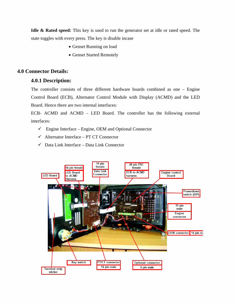
4.0.1 Description: The controller consists of three different hardware boards combined as one – Engine
Control Board (ECB), Alternator Control Module with Display (ACMD) and the LED
Board. Hence there are two internal interfaces:
ECB- ACMD and ACMD – LED Board. The controller has the following external
interfaces:
Engine Interface – Engine, OEM and Optional Connector
Alternator Interface – PT CT Connector
Data Link Interface – Data Link Connector
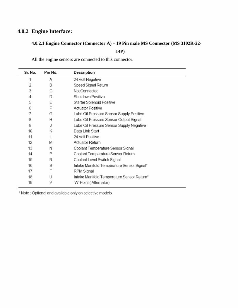
4.0.2 Engine Interface:
4.0.2.1 Engine Connector (Connector A) – 19 Pin male MS Connector (MS 3102R-22-
14P)
All the engine sensors are connected to this connector.

4.0.2.2 OEM Connector (Connector B) – 14 Pin male connector
All the discrete I/Os are connected to this connector.
Sample drawings related to each terminal of OEM connector are given below:
Remote Start Signal (Pin no. 4B)
Applying +24 volts DC (with respect to engine battery negative) through an external contact at
Pin 4B, remote start LED glows.
Procedure: Connect Positive supply on pin 4B and ground at pin 1B
NOTE: The signal may be pulse or continuous.
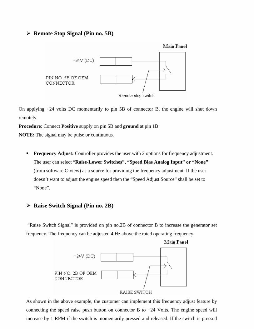
Remote Stop Signal (Pin no. 5B)
On applying +24 volts DC momentarily to pin 5B of connector B, the engine will shut down
remotely.
Procedure: Connect Positive supply on pin 5B and ground at pin 1B
NOTE: The signal may be pulse or continuous.
Frequency Adjust: Controller provides the user with 2 options for frequency adjustment.
The user can select “Raise-Lower Switches”, “Speed Bias Analog Input” or “None”
(from software C-view) as a source for providing the frequency adjustment. If the user
doesn’t want to adjust the engine speed then the “Speed Adjust Source” shall be set to
“None”.
Raise Switch Signal (Pin no. 2B)
“Raise Switch Signal” is provided on pin no.2B of connector B to increase the generator set
frequency. The frequency can be adjusted 4 Hz above the rated operating frequency.
As shown in the above example, the customer can implement this frequency adjust feature by
connecting the speed raise push button on connector B to +24 Volts. The engine speed will
increase by 1 RPM if the switch is momentarily pressed and released. If the switch is pressed
and held in that position then the engine speed will increase at a programmable rate (e.g. 2
RPM/ second).
Procedure: Connect Positive supply on pin 2B.
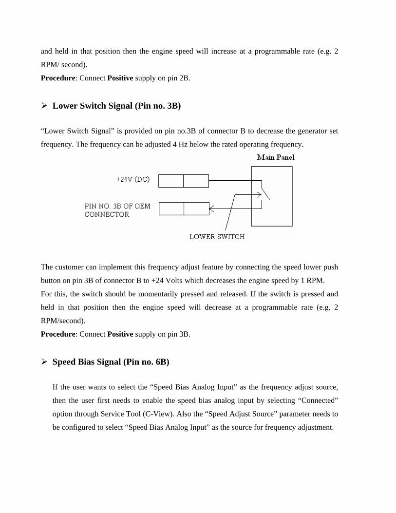
Lower Switch Signal (Pin no. 3B) “Lower Switch Signal” is provided on pin no.3B of connector B to decrease the generator set
frequency. The frequency can be adjusted 4 Hz below the rated operating frequency.
The customer can implement this frequency adjust feature by connecting the speed lower push
button on pin 3B of connector B to +24 Volts which decreases the engine speed by 1 RPM.
For this, the switch should be momentarily pressed and released. If the switch is pressed and
held in that position then the engine speed will decrease at a programmable rate (e.g. 2
RPM/second).
Procedure: Connect Positive supply on pin 3B.
Speed Bias Signal (Pin no. 6B) If the user wants to select the “Speed Bias Analog Input” as the frequency adjust source,
then the user first needs to enable the speed bias analog input by selecting “Connected”
option through Service Tool (C-View). Also the “Speed Adjust Source” parameter needs to
be configured to select “Speed Bias Analog Input” as the source for frequency adjustment.
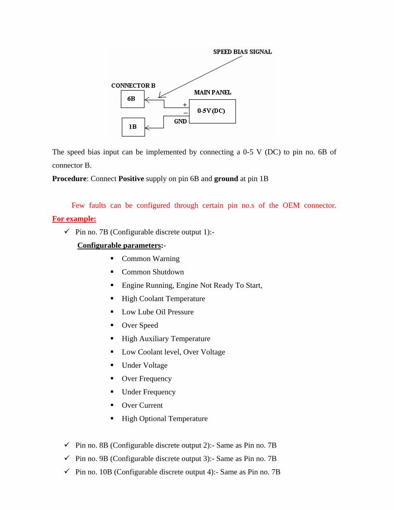
The speed bias input can be implemented by connecting a 0-5 V (DC) to pin no. 6B of
connector B.
Procedure: Connect Positive supply on pin 6B and ground at pin 1B
Few faults can be configured through certain pin no.s of the OEM connector.
For example:
Pin no. 7B (Configurable discrete output 1):-
Configurable parameters:-
Common Warning
Common Shutdown
Engine Running, Engine Not Ready To Start,
High Coolant Temperature
Low Lube Oil Pressure
Over Speed
High Auxiliary Temperature
Low Coolant level, Over Voltage
Under Voltage
Over Frequency
Under Frequency
Over Current
High Optional Temperature
Pin no. 8B (Configurable discrete output 2):- Same as Pin no. 7B
Pin no. 9B (Configurable discrete output 3):- Same as Pin no. 7B
Pin no. 10B (Configurable discrete output 4):- Same as Pin no. 7B
Pin no. 11B (Configurable discrete output 5):- Same as Pin no. 7B
Pin no. 12B (Not connected):- Same as Pin no. 7B and DATA LINK START.
4.0.2.3 Optional Connector (Connector C) – 6 Pin male Connector - usage of this connector depends on customer requirement.
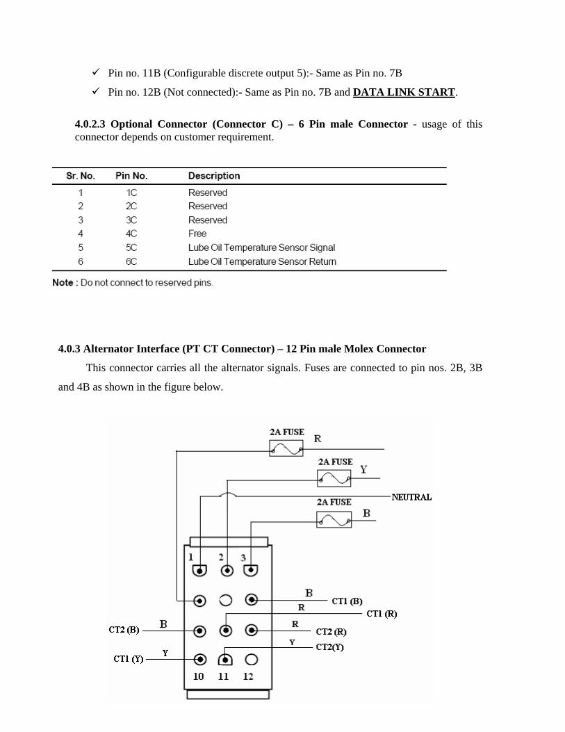
4.0.3 Alternator Interface (PT CT Connector) – 12 Pin male Molex Connector
This connector carries all the alternator signals. Fuses are connected to pin nos. 2B, 3B
and 4B as shown in the figure below.

4.0.4 Data Link Interface – DB9 female connector (RS-485 Communication)
This connector is used for serial communication.

5.0 Internal Interfaces: 5.0.1 ECB – ACMD Harness connection details
(20 pin FRC female-female harness with mating connectors on both the boards)

5.0.2 LED Board – ACMD Harness connection details (14 pin female-female harness with mating connectors on both the boards)
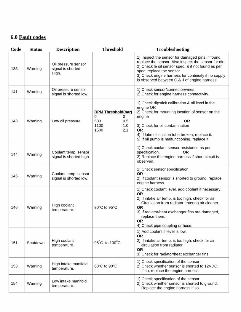
6.0 Fault codes Code Status Description Threshold Troubleshooting
135 Warning Oil pressure sensor signal is shorted High.
1) Inspect the sensor for damaged pins, if found, replace the sensor. Also inspect the sensor for dirt. 2) Check le oil sensor spec. & if not found as per spec. replace the sensor. 3) Check engine harness for continuity if no supply is observed between G & J of engine harness.
141 Warning Oil pressure sensor signal is shorted low.
1) Check sensor/connector/wires. 2) Check for engine harness connectivity.
143 Warning Low oil pressure.
RPM Threshold(bar) 0 0 500 0.5 1100 1.0 1500 2.1
1) Check dipstick calibration & oil level in the engine OR 2) Check for mounting location of sensor on the engine OR 3) Check for oil contamination OR 4) If lube oil suction tube broken, replace it. 5) If oil pump is malfunctioning, replace it.
144 Warning Coolant temp. sensor signal is shorted high.
1) Check coolant sensor resistance as per specification. OR 2) Replace the engine harness if short circuit is observed.
145 Warning Coolant temp. sensor signal is shorted low.
1) Check sensor specification. OR 2) If coolant sensor is shorted to ground, replace engine harness.
146 Warning High coolant temperature. 900C to 950C
1) Check coolant level, add coolant if necessary. OR 2) If intake air temp. is too high, check for air Circulation from radiator entering air cleaner. OR 3) If radiator/heat exchanger fins are damaged, replace them. OR 4) Check pipe coupling or hose.
151 Shutdown High coolant temperature. 950C to 1000C
1) Add coolant if level is low. OR 2) If intake air temp. is too high, check for air circulation from radiator. OR 3) Check for radiator/heat exchanger fins.
153 Warning High intake manifold temperature. 600C to 900C
1) Check specification of the sensor. 2) Check whether sensor is shorted to 12VDC. If so, replace the engine harness.
154 Warning Low intake manifold temperature.
1) Check specification of the sensor. 2) Check whether sensor is shorted to ground. Replace the engine harness if so.

155 Warning High auxillary
temperature. Check whether sensor is shorted to ground. Replace the engine harness if so.
234 Shutdown Overspeed shutdown.
110% of rated RPM for 1500 & 1800 rated RPM
1) Check whether the engine overspeed limit is calibrated at a sufficiently higher value than the r rated engine speed. OR 2) Replace the fuel actuator if it is stuck in the open position. OR 3) If the fuel actuator is getting 24VDC supply continuously, replace engine harness.
235 Shutdown Low coolant level shutdown.
1) If the coolant level is low, add coolant. 2) If coolant level sensor is faulty, replace it. OR 3) If +24V is obtained at pin 'R' of the engine harness then replace it.
359 Shutdown Engine fail to start.
1) Add fuel in the tank if level is low. OR 2) Replace the filter if it is choked OR 3) Tighten the fuel line connections if there is air in the Fuel. 4) Check the harness for open or short connection in the Fuel shutoff valve. 5) Check the engine harness for actuator supply.
415 Shutdown Low oil pressure.
RPM Threshold(bar) 0 0 500 0.3 1100 0.6 1500 2.4
1) Check oil level. 2) Check sensor location. 3) Check for contamination in the oil. 4) Replace oil filter if flow is blocked. 5) Remove oil sump if the suction tube is broken or the Tube seals are leaking. 6) Check sensor supply voltage at pin G & J of the Harness. 7) Check the continuity between connector 'A' and Harness. If no continuity is observed than replace it.
441 Warning Weak battery detected. Replace battery.
1411 Warning Speed bias analog input signal is shorted high.
Check OEM harness for short circuit i.e. +5V or +24V battery supply, if short replace it.
1416 Shutdown Engine fails to shutdown.
1) If FSO valve is permanently ON or even if switch is in OFF position, check the harness for +24V short to Battery supply. If short is observed replace the Harness. 2) Check and be sure that the manual override screw on FSO valve is out to maximum travel. 3) Check that the FSO is turned off when the 24V from Powercom is removed by turning the key switch from Run position to OFF position. 4) Check engine fuel drain line.
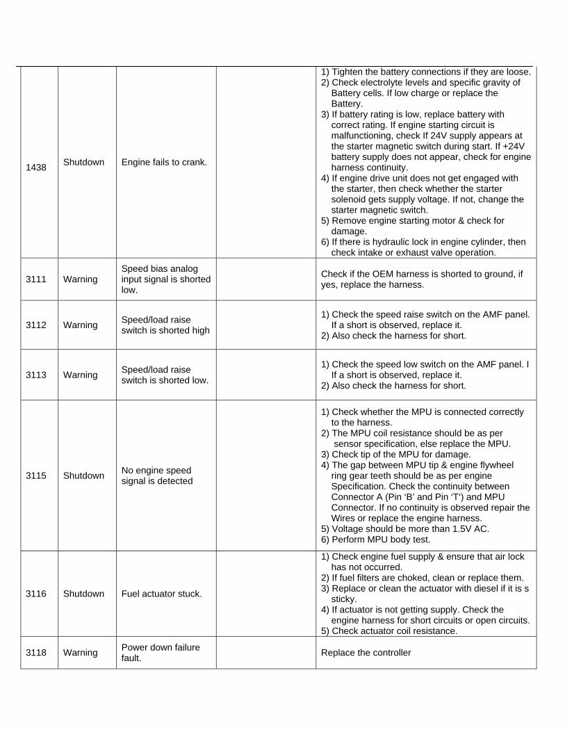
1438 Shutdown Engine fails to crank.
1) Tighten the battery connections if they are loose. 2) Check electrolyte levels and specific gravity of Battery cells. If low charge or replace the Battery. 3) If battery rating is low, replace battery with correct rating. If engine starting circuit is malfunctioning, check If 24V supply appears at the starter magnetic switch during start. If +24V battery supply does not appear, check for engine harness continuity. 4) If engine drive unit does not get engaged with the starter, then check whether the starter solenoid gets supply voltage. If not, change the starter magnetic switch. 5) Remove engine starting motor & check for damage. 6) If there is hydraulic lock in engine cylinder, then check intake or exhaust valve operation.
3111 Warning Speed bias analog input signal is shorted low.
Check if the OEM harness is shorted to ground, if yes, replace the harness.
3112 Warning Speed/load raise switch is shorted high
1) Check the speed raise switch on the AMF panel. If a short is observed, replace it. 2) Also check the harness for short.
3113 Warning Speed/load raise switch is shorted low.
1) Check the speed low switch on the AMF panel. I If a short is observed, replace it. 2) Also check the harness for short.
3115 Shutdown No engine speed signal is detected
1) Check whether the MPU is connected correctly to the harness. 2) The MPU coil resistance should be as per sensor specification, else replace the MPU. 3) Check tip of the MPU for damage. 4) The gap between MPU tip & engine flywheel ring gear teeth should be as per engine Specification. Check the continuity between Connector A (Pin ‘B’ and Pin ‘T‘) and MPU Connector. If no continuity is observed repair the Wires or replace the engine harness. 5) Voltage should be more than 1.5V AC. 6) Perform MPU body test.
3116 Shutdown Fuel actuator stuck.
1) Check engine fuel supply & ensure that air lock has not occurred. 2) If fuel filters are choked, clean or replace them. 3) Replace or clean the actuator with diesel if it is s sticky. 4) If actuator is not getting supply. Check the engine harness for short circuits or open circuits. 5) Check actuator coil resistance.
3118 Warning Power down failure fault. Replace the controller

1446 Shutdown Over voltage fault. 115% rated
1) Check for AVR function 2) Verify proper alternator connections. 3) Verify that PowerCom control voltage selection matches alternator winding voltage selection. 4) Isolate the power output from the generator set by opening the generator main circuit breaker. 5) Check voltage on the output terminals. If incorrect voltage is displayed, troubleshoot voltage sensing harness & circuitry. 6) If correct voltage is displayed, but it is very high, verify that the generator set can operate at proper voltage when exciter is powered from a suitable external source. 7) If voltage is unbalanced, troubleshoot main stator. 8) If voltage is balanced but abnormal, troubleshoot exciter & main field windings.
1447 Shutdown Under voltage fault. 85% rated
1) Check the load & correct for any overload. 2) Check operation by disconnecting the load & restarting the genset. 3) Verify proper alternator connections. 4) Verify that PowerCom control voltage selection matches alternator winding voltage selection. 5) Isolate the power output from the generator set by opening the generator main circuit breaker. 6) Check voltage on the output terminals. If incorrect voltage is displayed, troubleshoot voltage sensing harness & circuitry. 7) If correct voltage is displayed, but it is very high, verify that the generator set can operate at proper voltage when exciter is powered from a suitable external source. 8) If voltage is unbalanced, troubleshoot main Stator. 9) If voltage is balanced but abnormal, troubleshoot exciter & main field windings.
1448 Shutdown Over frequency fault. 110% rated 1) Reset the threshold to the lowest allowable setting. 2) Check for fuel or air delivery problem.
1449 Warning Under frequency fault. 85% rated
1) Check the load & correct for any overload. 2) Check operation by disconnecting the load & restarting the genset. 3) Reset the threshold to the lowest allowable setting. 4) Check for fuel or air delivery problem.
1471 Warning Over current fault. 120% rated
1) Check load & load cables. Repair if necessary. 2) Check operation by disconnecting load & restarting generator set. 3) Check CT ratio & CT connections.
3123 Warning Check input as per customer selection
3124 Shutdown Check input as per customer selection
3125 Warning Check input as per customer selection
3126 Shutdown Check input as per customer selection

Faults alongwith thresholds:
Sr. no
Fault name
Warning
Threshold
Shutdown Threshold
Time Threshold
(sec)
Comments
1.
Over voltage
-
115% of rated
5
Over voltage fault threshold
2.
Under voltage
85% of rated
-
5
Under voltage fault threshold
3.
Over Frequency
-
110% of rated
5
Over frequency fault threshold
4.
Under Frequency
85% of rated
-
10
Under frequency fault threshold
5.
Over Current
-
120% of rated
5
Over current fault threshold
LLOP warning tables according to no. of teeths Genset with 118 teeth – Warning
Warning Thresholds Voltage (DC) LLOP warning threshold for 0 rpm 0 LLOP warning threshold for 500 rpm 0.4 LLOP warning threshold for 1100 rpm 0.8 LLOP warning threshold for 1500 rpm 2.1 Genset with 142 teeth - Warning Warning Thresholds Voltage (DC) LLOP warning threshold for 0 rpm 0 LLOP warning threshold for 500 rpm 0.5 LLOP warning threshold for 1100 rpm 1 LLOP warning threshold for 1500 rpm 2.7

LLOP shutdown tables according to no. of teeths Genset with 118 teeth - Shutdown
Shutdown Thresholds Voltage (DC) LLOP warning threshold for 0 rpm 0 LLOP warning threshold for 500 rpm 0.3 LLOP warning threshold for 1100 rpm 0.6 LLOP warning threshold for 1500 rpm 1.8 Genset with 142 teeth - Shutdown Shutdown Thresholds Voltage (DC) LLOP warning threshold for 0 rpm 0 LLOP warning threshold for 500 rpm 0.3 LLOP warning threshold for 1100 rpm 0.6 LLOP warning threshold for 1500 rpm 2.4

7.0 SENSOR SPECIFICATIONS: 7.0.1 Engine Speed Sensor Torque = 34 to 47 Nm [25 to 35 ft-lb] Coil Resistance = 750 to 1600 ohms 7.0.2 Pressure Sensor Torque = 14 Nm [124 in-lb]
Pressure (kPa)
Pressure (psia)
Voltage (VDC)
0 0 0.5 207 30 1.5 414 60 2.5 621 90 3.5 827 120 4.5
All Temperature Sensors Torque = 15 Nm [133 in-lb]
Temperature (°C)
Temperature (°F)
Resistance (Ohm)
0 32 30k to 36k 25 77 9k to 11k 50 122 3k to 4k 75 167 1.35k to 1.5k 100 212 600 ohm to 675 ohm

Interfacing PowerCom with a PC :-
The datalink connector is 9 pin ‘D’ type connector interfacing with PC based
service tool. The data link is intended to be used to connect single or multiple PowerCom
to a host computer acting as a supervisor for facilitating data acquisition and logging using
a PC based service tool. There are many features of the PowerCom that are configured
using the service tool. Electronic service tool is a packaged software application that
installs on an IBM compatible PC. The Service Tool is available as a Kit (Part No.
4105287) on a CD. The Service PC, running the PowerCom Tool is connected to the
PowerCom via a RS-232 serial communication cable. The data link uses two wire RS-485
serial communication standard. A RS- 485 to RS-232 converter kit (Part No. 4071717) is
required for connecting the data link to a PC’s RS-232 serial communication port.

8.0 ALL POWERCOM’S DO NOT NEED CALIBRATION. THEY ARE DUELY CALIBRATED. IF AT ALL REQUIRED THEN FOLLOW THE FOLLOWING STEPS. Calibration Procedure:- Powercom can be calibrated through the software C-view.
For calibrating through C-view, connect controller to PC using the data link connector and
RS232-RS485 converter and follow the given steps as an example for calibration:-
1. Goto tool setup utility and enter the engine control board serial number and select the
type of controller used. Click add to save the *.cfg file.
2. Open C-view to select the site & identify the controller.

3. Click on “CONNECT” to start calibration.
4. After connecting to Powercom, a screen is observed with various adjustable and
observable parameters. Click on ‘CALIBRATE’ for calibration of controller.
5. A screen appears in which we have to select the type of controller and the engine
model. Then select *.cal file and select dash (-) for engine model and then press OK
for calibration.
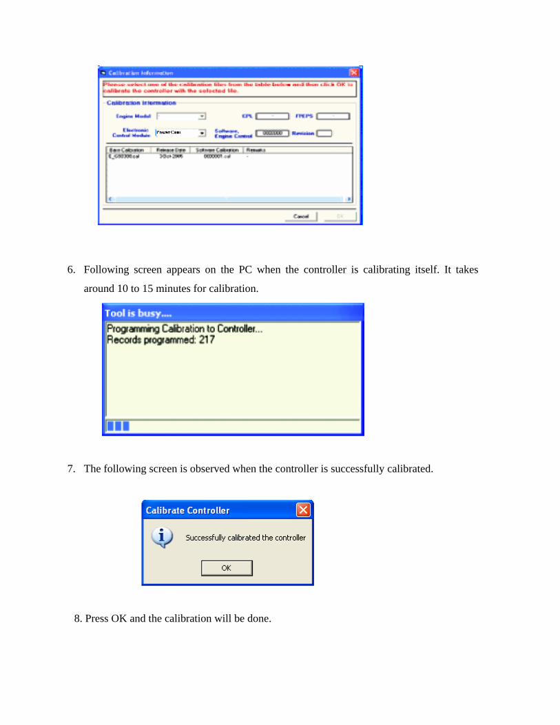
6. Following screen appears on the PC when the controller is calibrating itself. It takes
around 10 to 15 minutes for calibration.
7. The following screen is observed when the controller is successfully calibrated.
8. Press OK and the calibration will be done.
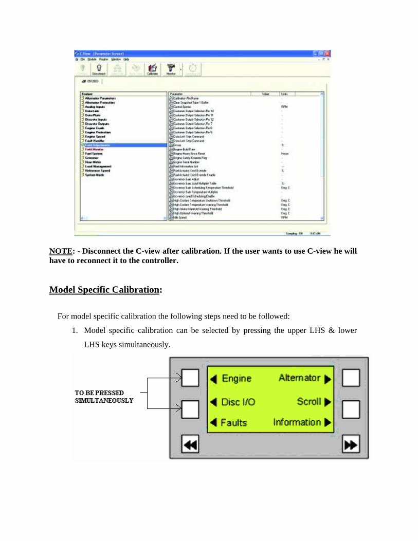
NOTE: - Disconnect the C-view after calibration. If the user wants to use C-view he will have to reconnect it to the controller. Model Specific Calibration:
For model specific calibration the following steps need to be followed:
1. Model specific calibration can be selected by pressing the upper LHS & lower
LHS keys simultaneously.
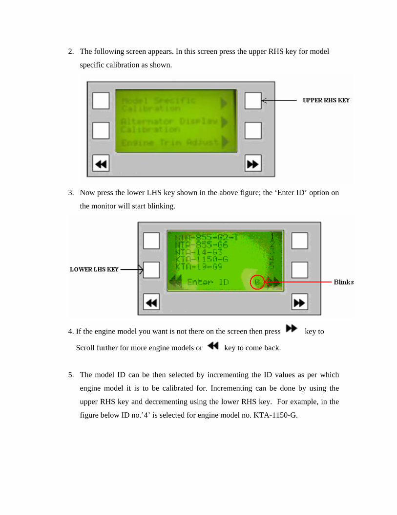
2. The following screen appears. In this screen press the upper RHS key for model
specific calibration as shown.
3. Now press the lower LHS key shown in the above figure; the ‘Enter ID’ option on
the monitor will start blinking.
4. If the engine model you want is not there on the screen then press key to
Scroll further for more engine models or key to come back.
5. The model ID can be then selected by incrementing the ID values as per which
engine model it is to be calibrated for. Incrementing can be done by using the
upper RHS key and decrementing using the lower RHS key. For example, in the
figure below ID no.’4’ is selected for engine model no. KTA-1150-G.

6. This value can also be saved by pressing the lower LHS key.
7. The following screen will appear and the PowerCom will be calibrated for that
specific model.

Note: The model should appear on the screen while setting.
For example:
In the above screen, the ID entered is ‘1’, but the engine model with ID equal to 1 is
not displayed in the screen. So, in this case when we try to save this value it will not
get saved.
NOTE: - This setting changes only the display value of this parameter and not the real alternator output value.
Part numbers of C-view converter
4071851 Converter to PC communication cable
4071853 C-view to converter communication cable 1
4071852 C-view to converter communication cable 2
4084227 C-view to Converter Comm. Cable for Bootloader
4071717 RS232 to RS485 converter
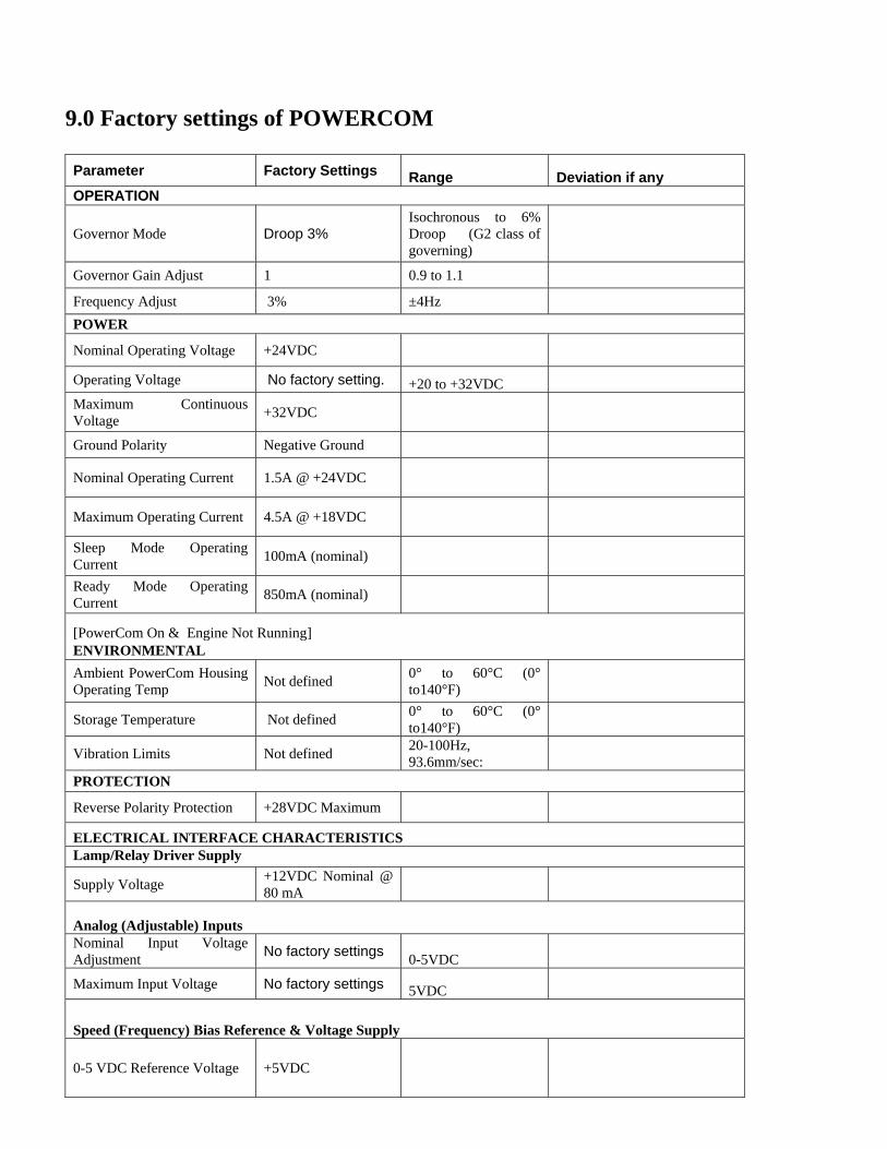
9.0 Factory settings of POWERCOM
Parameter Factory Settings Range Deviation if any OPERATION
Governor Mode Droop 3% Isochronous to 6% Droop (G2 class of governing)
Governor Gain Adjust 1 0.9 to 1.1 Frequency Adjust 3% ±4Hz POWER
Nominal Operating Voltage +24VDC
Operating Voltage No factory setting. +20 to +32VDC
Maximum Continuous Voltage +32VDC
Ground Polarity Negative Ground
Nominal Operating Current 1.5A @ +24VDC
Maximum Operating Current 4.5A @ +18VDC
Sleep Mode Operating Current 100mA (nominal)
Ready Mode Operating Current 850mA (nominal)
[PowerCom On & Engine Not Running] ENVIRONMENTAL Ambient PowerCom Housing Operating Temp Not defined 0° to 60°C (0°
to140°F)
Storage Temperature Not defined 0° to 60°C (0° to140°F)
Vibration Limits Not defined 20-100Hz, 93.6mm/sec:
PROTECTION
Reverse Polarity Protection +28VDC Maximum ELECTRICAL INTERFACE CHARACTERISTICS Lamp/Relay Driver Supply
Supply Voltage +12VDC Nominal @ 80 mA
Analog (Adjustable) Inputs Nominal Input Voltage Adjustment No factory settings 0-5VDC
Maximum Input Voltage No factory settings 5VDC
Speed (Frequency) Bias Reference & Voltage Supply
0-5 VDC Reference Voltage +5VDC

10.0 Wiring Diagram

11.0 Parameters to be logged on Hourly Basis


![PROFIBUS Guideline Commissioning[1]](https://img.pdfslide.us/doc/110x75/55cf9974550346d0339d7bb6/profibus-guideline-commissioning1.jpg)