Embed Size (px)
Citation preview

- 1
2
3
4
5
6
7
8
Document Number: DSP1085
Date: 2010-01-12
Version: 1.0.0
Power Utilization Management Profile
Document Type: Specification
Document Status: DMTF Standard
Document Language: E

Power Utilization Management Profile DSP1085
2 DMTF Standard Version 1.0.0
Copyright Notice 9
Copyright © 2010 Distributed Management Task Force, Inc. (DMTF). All rights reserved. 10
11 12 13 14
15 16 17 18 19 20 21 22 23 24 25 26 27
28 29
DMTF is a not-for-profit association of industry members dedicated to promoting enterprise and systems management and interoperability. Members and non-members may reproduce DMTF specifications and documents, provided that correct attribution is given. As DMTF specifications may be revised from time to time, the particular version and release date should always be noted.
Implementation of certain elements of this standard or proposed standard may be subject to third party patent rights, including provisional patent rights (herein "patent rights"). DMTF makes no representations to users of the standard as to the existence of such rights, and is not responsible to recognize, disclose, or identify any or all such third party patent right, owners or claimants, nor for any incomplete or inaccurate identification or disclosure of such rights, owners or claimants. DMTF shall have no liability to any party, in any manner or circumstance, under any legal theory whatsoever, for failure to recognize, disclose, or identify any such third party patent rights, or for such party’s reliance on the standard or incorporation thereof in its product, protocols or testing procedures. DMTF shall have no liability to any party implementing such standard, whether such implementation is foreseeable or not, nor to any patent owner or claimant, and shall have no liability or responsibility for costs or losses incurred if a standard is withdrawn or modified after publication, and shall be indemnified and held harmless by any party implementing the standard from any and all claims of infringement by a patent owner for such implementations.
For information about patents held by third-parties which have notified the DMTF that, in their opinion, such patent may relate to or impact implementations of DMTF standards, visit http://www.dmtf.org/about/policies/disclosures.php. 30
DSP1085 Power Utilization Management Profile
Version 1.0.0 DMTF Standard 3
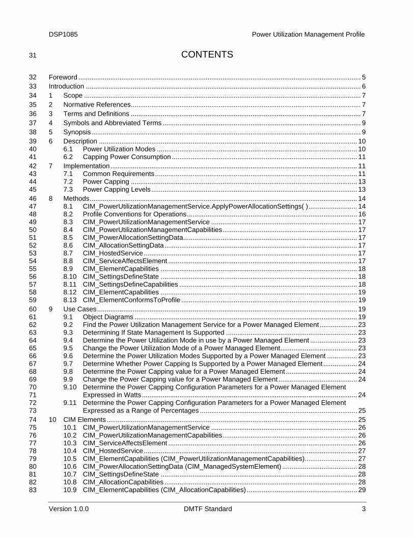
CONTENTS 31
32 33 34 35 36 37 38 39 40 41 42 43 44 45 46 47 48 49 50 51 52 53 54 55 56 57 58 59 60 61 62 63 64 65 66 67 68 69 70 71 72 73 74 75 76 77 78 79 80 81 82 83
Foreword ....................................................................................................................................................... 5 Introduction ................................................................................................................................................... 6 1 Scope .................................................................................................................................................... 7 2 Normative References........................................................................................................................... 7 3 Terms and Definitions ........................................................................................................................... 7 4 Symbols and Abbreviated Terms .......................................................................................................... 9 5 Synopsis................................................................................................................................................ 9 6 Description .......................................................................................................................................... 10
6.1 Power Utilization Modes ........................................................................................................... 10 6.2 Capping Power Consumption ................................................................................................... 11
7 Implementation.................................................................................................................................... 11 7.1 Common Requirements............................................................................................................ 11 7.2 Power Capping ......................................................................................................................... 13 7.3 Power Capping Levels .............................................................................................................. 13
8 Methods............................................................................................................................................... 14 8.1 CIM_PowerUtilizationManagementService.ApplyPowerAllocationSettings( ).......................... 14 8.2 Profile Conventions for Operations........................................................................................... 16 8.3 CIM_PowerUtilizationManagementService .............................................................................. 17 8.4 CIM_PowerUtilizationManagementCapabilities........................................................................ 17 8.5 CIM_PowerAllocationSettingData............................................................................................. 17 8.6 CIM_AllocationSettingData....................................................................................................... 17 8.7 CIM_HostedService.................................................................................................................. 17 8.8 CIM_ServiceAffectsElement ..................................................................................................... 17 8.9 CIM_ElementCapabilities ......................................................................................................... 18 8.10 CIM_SettingsDefineState ......................................................................................................... 18 8.11 CIM_SettingsDefineCapabilities ............................................................................................... 18 8.12 CIM_ElementCapabilities ......................................................................................................... 19 8.13 CIM_ElementConformsToProfile .............................................................................................. 19
9 Use Cases........................................................................................................................................... 19 9.1 Object Diagrams ....................................................................................................................... 19 9.2 Find the Power Utilization Management Service for a Power Managed Element.................... 23 9.3 Determining If State Management Is Supported ...................................................................... 23 9.4 Determine the Power Utilization Mode in use by a Power Managed Element ......................... 23 9.5 Change the Power Utilization Mode of a Power Managed Element......................................... 23 9.6 Determine the Power Utilization Modes Supported by a Power Managed Element ................ 23 9.7 Determine Whether Power Capping Is Supported by a Power Managed Element.................. 24 9.8 Determine the Power Capping value for a Power Managed Element ...................................... 24 9.9 Change the Power Capping value for a Power Managed Element .......................................... 24 9.10 Determine the Power Capping Configuration Parameters for a Power Managed Element
Expressed in Watts ................................................................................................................... 24 9.11 Determine the Power Capping Configuration Parameters for a Power Managed Element
Expressed as a Range of Percentages .................................................................................... 25 10 CIM Elements...................................................................................................................................... 25
10.1 CIM_PowerUtilizationManagementService .............................................................................. 26 10.2 CIM_PowerUtilizationManagementCapabilities........................................................................ 26 10.3 CIM_ServiceAffectsElement ..................................................................................................... 26 10.4 CIM_HostedService.................................................................................................................. 27 10.5 CIM_ElementCapabilities (CIM_PowerUtilizationManagementCapabilities)............................ 27 10.6 CIM_PowerAllocationSettingData (CIM_ManagedSystemElement) ........................................ 28 10.7 CIM_SettingsDefineState ......................................................................................................... 28 10.8 CIM_AllocationCapabilities ....................................................................................................... 28 10.9 CIM_ElementCapabilities (CIM_AllocationCapabilities) ........................................................... 29
Power Utilization Management Profile DSP1085
4 DMTF Standard Version 1.0.0
10.10 CIM_PowerAllocationSettingData (CIM_AllocationCapabilities) .............................................. 29 84 85 86 87 88
89
90 91 92 93 94 95
10.11 CIM_SettingsDefineCapabilities ............................................................................................... 29 10.12 CIM_RegisteredProfile.............................................................................................................. 30
ANNEX A (Informative) Change Log ......................................................................................................... 31
Figures Figure 1 – Power Utilization Management Profile: Class Diagram............................................................. 10 Figure 2 – Power Utilization Modes ............................................................................................................ 20 Figure 3 – Power Capping .......................................................................................................................... 20 Figure 4 – Power Capping Configuration Using Watts ............................................................................... 21 Figure 5 – Power Capping Configuration Using Percent Power................................................................. 22
Tables 96
97 98 99
100 101 102 103 104 105 106 107 108 109 110 111 112 113 114 115 116 117 118 119 120 121 122 123 124
125
Table 1 – Related Profiles............................................................................................................................. 9 Table 2 – EnabledState Value Descriptions ............................................................................................... 12 Table 3 – RequestedState Property Value Descriptions ............................................................................ 12 Table 4 – RequestedState Parameter Value Descriptions ......................................................................... 12 Table 5 – TransitioningToState Property Value Descriptions ..................................................................... 12 Table 6 – ApplyPowerAllocationSettings( ) Method: Parameters ............................................................... 14 Table 7 – ApplyPowerAllocationSettings( ) Method: Return Code Values.................................................. 15 Table 8 – ApplyPowerAllocationSettings( ) Method: Standard Messages ................................................. 15 Table 9 – CIM_HostedService .................................................................................................................... 17 Table 10 – CIM_ServiceAffectsElement ..................................................................................................... 18 Table 11 – CIM_ElementCapabilities.......................................................................................................... 18 Table 12 – CIM_SettingsDefineState.......................................................................................................... 18 Table 13 – CIM_SettingsDefineCapabilities ............................................................................................... 19 Table 14 – CIM_ElementCapabilities.......................................................................................................... 19 Table 15 – CIM_ElementConformsToProfile .............................................................................................. 19 Table 16 – CIM Elements: Power Utilization Management Profile ............................................................. 25 Table 17 – Class: CIM_PowerUtilizationManagementService ................................................................... 26 Table 18 – Class: CIM_PowerUtilizationManagementCapabilities............................................................. 26 Table 19 – Class: CIM_ServiceAffectsElement .......................................................................................... 27 Table 20 – Class: CIM_HostedService ....................................................................................................... 27 Table 21 – CIM_ElementCapabilities.......................................................................................................... 27 Table 22 – CIM_PowerAllocationSettingData............................................................................................. 28 Table 23 – CIM_SettingDefinesState.......................................................................................................... 28 Table 24 – CIM_AllocationCapabilities ....................................................................................................... 28 Table 25 – CIM_ElementCapabilities.......................................................................................................... 29 Table 26 – CIM_PowerAllocationSettingData............................................................................................. 29 Table 27 – CIM_SettingsDefineCapabilities ............................................................................................... 30 Table 28 – Class: CIM_RegisteredProfile................................................................................................... 30
DSP1085 Power Utilization Management Profile
Version 1.0.0 DMTF Standard 5
Foreword 126
127 128
129 130
131
132
133
134
135
136
137
138
139
140
141
142
143
144
145
The Power Utilization Management Profile (DSP1085) was prepared by the Physical Platform Profiles Working Group.
DMTF is a not-for-profit association of industry members dedicated to promoting enterprise and systems management and interoperability.
Acknowledgements
The authors wish to acknowledge the following people.
Editor:
• David Judkovics – IBM
Contributors:
• Andreas Maier – IBM
• Aaron Merkin – Dell
• Khachatur Papanyan – Dell
• John Leung – Intel
• Sharon Smith – Intel
• John Parchem – Microsoft
• Bob Blair – AMD
• Jeff Hilland – HP
• Dr. Hemal Shah – Broadcom

Power Utilization Management Profile DSP1085
6 DMTF Standard Version 1.0.0
Introduction 146
147 148 149
150 151
The information in this specification and referenced specifications should be sufficient for a provider or consumer of this data to identify unambiguously the classes, properties, methods, and values that shall be instantiated and manipulated to represent and manage a power utilization management service.
The target audience for this specification is implementers who are writing CIM-based providers or consumers of management interfaces that represent the component described in this document.
DSP1085 Power Utilization Management Profile
Version 1.0.0 DMTF Standard 7
Power Utilization Management Profile 152
154 155 156
158 159 160
161
1 Scope 153
The Power Utilization Management Profile extends the management capabilities of referencing profiles by adding the capability to represent and manage the power utilization configuration of a managed element within a computer system.
2 Normative References 157
The following referenced documents are indispensable for the application of this document. For dated references, only the edition cited applies. For undated references, the latest edition of the referenced document (including any amendments) applies.
DMTF DSP0004, CIM Infrastructure Specification 2.5, http://www.dmtf.org/standards/published_documents/DSP0004_2.5.pdf 162
163 DMTF DSP0200, CIM Operations over HTTP 1.3, http://www.dmtf.org/standards/published_documents/DSP0200_1.3.pdf 164
165 DMTF DSP1001, Management Profile Specification Usage Guide 1.0, http://www.dmtf.org/standards/published_documents/DSP1001_1.0.pdf 166
167 DMTF DSP1033, Profile Registration Profile 1.0, http://www.dmtf.org/standards/published_documents/DSP1033_1.0.pdf 168
169 DMTF DSP1041, Resource Allocation Profile 1.1, http://www.dmtf.org/standards/published_documents/DSP1041_1.1.pdf 170
171 DMTF DSP1043, Allocation Capabilities Profile 1.0, http://www.dmtf.org/standards/published_documents/DSP1043_1.0.pdf 172
173 DMTF DSP1080, Enabled Logical Element Profile 1.0, http://www.dmtf.org/standards/published_documents/DSP1080_1.0.pdf 174
175 DMTF DSP8016, WBEM Operations Message Registry 1.0, http://schemas.dmtf.org/wbem/messageregistry/1/dsp8016.xml 176
177 ISO/IEC Directives, Part 2, Rules for the structure and drafting of International Standards, http://isotc.iso.org/livelink/livelink.exe?func=ll&objId=4230456&objAction=browse&sort=subtype 178
180
182 183
185 186
3 Terms and Definitions 179
For the purposes of this document, the following terms and definitions apply.
3.1 181 can used for statements of possibility and capability, whether material, physical, or causal
3.2 184 cannot used for statements of possibility and capability, whether material, physical, or causal

Power Utilization Management Profile DSP1085
8 DMTF Standard Version 1.0.0
3.3 187 conditional 188
189 190
192 193 194
196 197
199 200
202 203
205 206 207
209 210 211
213 214 215
217 218 219
221 222
224 225
227 228
indicates requirements to be followed strictly in order to conform to the document when the specified conditions are met
3.4 191 mandatory indicates requirements to be followed strictly in order to conform to the document and from which no deviation is permitted
3.5 195 may indicates a course of action permissible within the limits of the document
3.6 198 need not indicates a course of action permissible within the limits of the document
3.7 201 optional indicates a course of action permissible within the limits of the document
3.8 204 referencing profile indicates a profile that owns the definition of this class and can include a reference to this profile in its “Related Profiles” table
3.9 208 shall indicates requirements to be followed strictly in order to conform to the document and from which no deviation is permitted
3.10 212 shall not indicates requirements to be followed strictly in order to conform to the document and from which no deviation is permitted
3.11 216 should indicates that among several possibilities, one is recommended as particularly suitable, without mentioning or excluding others, or that a certain course of action is preferred but not necessarily required
3.12 220 should not indicates that a certain possibility or course of action is deprecated but not prohibited
3.13 223 Power Managed Element the computer system whose power utilization is being managed
3.14 226 Dynamic Power Savings Mode power savings mode that relies on internal feedback to limit power consumption

DSP1085 Power Utilization Management Profile
Version 1.0.0 DMTF Standard 9
3.15 229 Power Capping 230
231 232
235 236
238
239
240
241
242 243
244
245
246 247
248 249
250 251 252
253
254
system function that is active power management based on dynamic and static configuration of system operation for a well defined goal: the system's power capping level
4 Symbols and Abbreviated Terms 233
4.1 234 CIM Common Information Model
5 Synopsis 237
Profile Name: Power Utilization Management
Version: 1.0.0
Organization: DMTF
CIM Schema Version: 2.21
Specializes: Enabled Logical Element Profile, Allocation Capabilities Profile, and Resource Allocation Profile
Central Class: CIM_PowerUtilizationManagementService
Scoping Class: CIM_ComputerSystem
The Power Utilization Management Profile extends the management elements of referencing profiles by adding the capability to represent Power Consumption management to a Power Managed Element.
CIM_PowerUtilizationManagementService shall be the central class of this profile. The instance of CIM_PowerUtilizationManagementService shall be the Central Instance of this profile.
CIM_ManagedSystemElement shall be the scoping class of this profile. The instance of CIM_ManagedSystemElement with which the central instance is associated through an instance of CIM_HostedService shall be the scoping instance of this profile.
Table 1 identifies profiles on which this profile has a dependency.
Table 1 – Related Profiles
Profile Name Organization Version Relationship
Profile Registration DMTF 1.0 Mandatory
Enabled Logical Element DMTF 1.0 Specializes
Allocation Capabilities DMTF 1.0 Specializes
Resource Allocation DMTF 1.1 Specializes
Power Utilization Management Profile DSP1085
6 Description 255
256 257 258 259
260 261
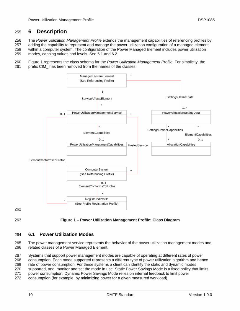
The Power Utilization Management Profile extends the management capabilities of referencing profiles by adding the capability to represent and manage the power utilization configuration of a managed element within a computer system. The configuration of the Power Managed Element includes power utilization modes, capping values and levels. See 6.1 and 6.2.
Figure 1 represents the class schema for the Power Utilization Management Profile. For simplicity, the prefix CIM_ has been removed from the names of the classes.
ComputerSystem(See Referencing Profile)
ElementCapabilities
HostedService
*
ServiceAffectsElement
1
*
PowerUtilizationManagementService
1
*
*
**
0..1PowerUtilizationManagmentCapabilities
ElementCapabilities
SettingsDefineState
1..*
0..1
PowerAllocationSettingData
AllocationCapabilties
SettingsDefineCapabilities
*
RegisteredProfile(See Profile Registration Profile)
ElementConformsToProfile
*
0..1
ElementConformsToProfile
*
0..1
ManagedSystemElement(See Referencing Profile)
1
262
263
265 266
267 268 269 270 271 272
Figure 1 – Power Utilization Management Profile: Class Diagram
6.1 Power Utilization Modes 264
The power management service represents the behavior of the power utilization management modes and related classes of a Power Managed Element.
Systems that support power management modes are capable of operating at different rates of power consumption. Each mode supported represents a different type of power utilization algorithm and hence rate of power consumption. For these systems a client can identify the static and dynamic modes supported, and, monitor and set the mode in use. Static Power Savings Mode is a fixed policy that limits power consumption. Dynamic Power Savings Mode relies on internal feedback to limit power consumption (for example, by minimizing power for a given measured workload).
10 DMTF Standard Version 1.0.0

DSP1085 Power Utilization Management Profile
Version 1.0.0 DMTF Standard 11
The power management service provides the ability to monitor and set the current power utilization mode and is represented by the CIM_PowerUtilizationManagementService class. The supported power utilization modes of the Power Managed Element are represented by the CIM_PowerUtilizationManagementCapabilities class, which is associated to the CIM_PowerUtilizationManagementService class through the CIM_ElementCapabilities association.
273 274 275 276 277
279 280
281 282 283
284 285 286 287
289 290
292 293
295
296 297 298
299 300 301
303 304
6.2 Capping Power Consumption 278
Power capping system function is the active management based on dynamic and static configuration of system operation for a well defined goal: the system’s power capping level.
The power capping level is represented by the CIM_PowerAllocationSettingData class associated to the Power Managed Element through the CIM_SettingsDefineState association. This instance represents the power capping aspect of the system.
When there are one or more configurations/settings or a range of values which can constrain the power cap of the Power Managed Element, those configurations/settings are represented by CIM_PowerAllocationSettingData class associated to the CIM_AllocationCapabilities class through the CIM_SettingsDefineCapabilities.
7 Implementation 288
This clause details the requirements related to the arrangement of instances and their properties for implementations of this profile.
7.1 Common Requirements 291
This section provides normative requirements for representation and management of the power utilization configuration. The requirements in this clause are mandatory.
7.1.1 CIM_PowerUtilizationManagementService 294
There shall be one instance of CIM_PowerUtilizationManagementService implemented.
There shall be one and only one instance of CIM_PowerUtilizationManagementService associated with the instance of CIM_ManagedSystemElement that represents the Power Managed Element and associated through an instance of CIM_ServiceAffectsElement.
The CIM_ManagedSystemElement, which represents the system that is hosting the power management service, shall be associated to CIM_PowerUtilizationManagementService with an instance of CIM_HostedService association.
7.1.1.1 State Management of CIM_PowerUtilizationManagementService 302
This clause describes constraints related to the interpretation of states specific to modeling power utilization management services. An implementation may support management of CIM_PowerUtilizationManagementService state. The abstract DSP1080 (Enabled Logical Element Profile) specifies requirements for supporting state management in sub-classes of CIM_EnabledLogicalElement. The implementation of CIM_PowerUtilizationManagementService shall meet the requirements of the Enabled Logical Element Profile, with CIM_PowerUtilizationManagementService in place of CIM_EnabledLogicalElement and CIM_PowerUtilizationManagementCapabilities in place of CIM_EnabledLogicalElementCapabilities.
305 306 307 308 309 310
312 313
7.1.1.1.1 Enabled State 311
The CIM_PowerUtilizationManagementService.EnabledState property shall have one the following values: 0 (Unknown), 2 (Enabled), or 3 (Disabled).
Power Utilization Management Profile DSP1085
12 DMTF Standard Version 1.0.0
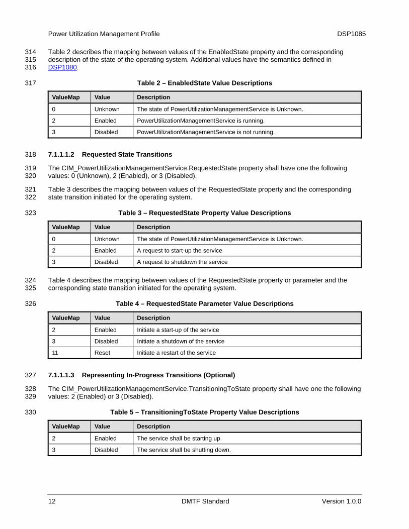
Table 2 describes the mapping between values of the EnabledState property and the corresponding description of the state of the operating system. Additional values have the semantics defined in
314 315
DSP1080. 316
317 Table 2 – EnabledState Value Descriptions
ValueMap Value Description
0 Unknown The state of PowerUtilizationManagementService is Unknown.
2 Enabled PowerUtilizationManagementService is running.
3 Disabled PowerUtilizationManagementService is not running.
7.1.1.1.2 Requested State Transitions 318
The CIM_PowerUtilizationManagementService.RequestedState property shall have one the following values: 0 (Unknown), 2 (Enabled), or 3 (Disabled).
319 320
321 322
323
Table 3 describes the mapping between values of the RequestedState property and the corresponding state transition initiated for the operating system.
Table 3 – RequestedState Property Value Descriptions
ValueMap Value Description
0 Unknown The state of PowerUtilizationManagementService is Unknown.
2 Enabled A request to start-up the service
3 Disabled A request to shutdown the service
Table 4 describes the mapping between values of the RequestedState property or parameter and the corresponding state transition initiated for the operating system.
324 325
326 Table 4 – RequestedState Parameter Value Descriptions
ValueMap Value Description
2 Enabled Initiate a start-up of the service
3 Disabled Initiate a shutdown of the service
11 Reset Initiate a restart of the service
7.1.1.1.3 Representing In-Progress Transitions (Optional) 327
The CIM_PowerUtilizationManagementService.TransitioningToState property shall have one the following values: 2 (Enabled) or 3 (Disabled).
328 329
330 Table 5 – TransitioningToState Property Value Descriptions
ValueMap Value Description
2 Enabled The service shall be starting up.
3 Disabled The service shall be shutting down.

DSP1085 Power Utilization Management Profile
Version 1.0.0 DMTF Standard 13
7.1.1.1.4 Representing Available Requested States (Optional) 331
The CIM_PowerUtilizationManagementCapabilities.RequestedStatesSupported property may contain zero or more of the following values: 2 (Enabled), 3 (Disabled), or 11 (Reset).
332 333
335 336
337 338
340 341 342
344 345 346 347
348 349
350
352 353 354
356 357
7.1.2 CIM_PowerUtilizationManagementCapabilities 334
The capabilities of the power management service shall be represented by an instance of CIM_PowerUtilizationManagementCapabilities.
There shall be an instance of CIM_PowerUtilizationManagementCapabilities associated with an instance of CIM_PowerUtilizationManagementService through the CIM_ElementCapabilities association.
7.2 Power Capping 339
This clause details requirement for representation and management of the power capping. If the power capping of the managed element within a computer system is supported, the requirements specified in this clause shall be met.
7.2.1 Power Aspect — CIM_PowerAllocationSettingData 343
There may be one or more instances of CIM_PowerAllocationSettingData associated with a Power Managed Element through an instance of CIM_SettingsDefinedState. These instances shall represent the power consumption characteristics of the Power Managed Element. The characteristics include power capping and reservation.
The power cap of the Power Managed Element shall be represented by the Limit property in units described by the AllocationUnits property of the CIM_PowerAllocationSettingData instance.
If the power cap for the Power Managed Element is disabled, the Limit property shall be set to NULL.
7.3 Power Capping Levels 351
This subclause details requirement for representation and management of the power capping levels. If the representation of power capping levels of the managed element within a computer system is supported, the requirements specified in this subclause shall be met.
7.3.1 CIM_AllocationCapabilities 355
There shall be one or more instances of CIM_AllocationCapabilities associated to the CIM_PowerAllocationSettingData that represents the power consumption characteristics of the Power Managed Element (see 7.2) through the CIM_ElementCapabilities association. See DSP1043 for detailed requirements on supporting multiple CIM_AllocationCapabilities.
358 359
361 362 363 364
365 366 367 368 369
7.3.2 Power Configurations — CIM_PowerAllocationSettingData 360
There shall be one or more instances of CIM_PowerAllocationSettingData associated through the CIM_SettingsDefineCapabilities association to an instance of CIM_AllocationCapabilities. These instances of CIM_PowerAllocationSettingData shall represent the different power capping levels of the Power Managed Element or information that constrains the possible custom power capping levels.
The actual power cap level shall be represented by the Limit property in units described by the AllocationUnits property of the CIM_PowerAllocationSettingData instance. The AllocationUnits property shall contain “watts” or “percent.” If percent is used it is intended to express a range of power capping from a state of no capping, 0 percent, to the state of maximum capping, 100 percent. It is intended to allow power-capping control without quantifiable power values being expressed.

Power Utilization Management Profile DSP1085
14 DMTF Standard Version 1.0.0
8 Methods 370
This section details the requirements for supporting intrinsic operations and extrinsic methods for the CIM elements defined by this profile.
371 372
374 375 376 377
378 379 380 381
382 383 384
385
386
8.1 CIM_PowerUtilizationManagementService.ApplyPowerAllocationSettings( ) 373
A successful execution of the CIM_PowerUtilizationManagementService.ApplyPowerAllocationSettings() method shall modify the power settings in the managed environment that are represented by an instance of class CIM_PowerAllocationSettings that is identified by the value of the PowerAllocationSettings.InstanceId property, such that:
• non-NULL values of properties of the embedded instance of the CIM_PowerAllocationSettingData class that is provided through the PowerAllocationSettings parameter, shall update the settings in the managed environment that are represented by that CIM_PowerAllocationSettings instance.
• a NULL value of the PowerAllocationSettings.Limit and AllocationUnits properties shall disable Power Capping in the the settings in the managed environment that are represented by that CIM_PowerAllocationSettings instance.
Table 6 contains requirements for parameters of this method.
Table 6 – ApplyPowerAllocationSettings( ) Method: Parameters
Qualifiers Name Type Description/Values
IN PowerAllocationSettings EmbeddedInstance ( "CIM_PowerAllocationSettingData") String
See 8.1.2.
OUT Job CIM_ConcreteJob REF See 8.1.4 and 8.1.5.
8.1.1 Conditional Support 387
This method is conditional on the CIM_PowerUtilizationManagementService.SupportedMethods property array containing a value of 2 (ApplyPowerAllocationSettings). For more information, see 7.2.1.
388 389
390
391 392
393 394
396
397 398
399 400 401
402 403 404
If this method is not implemented, the following applies:
• If standard messages are not implemented for this method, the method shall return a value of 1 (Method is not supported).
• If standard messages are implemented for this method, the method invocation shall fail with message WIPG0219 (Method not supported by class implementation).
8.1.2 PowerAllocationSettings Parameter 395
If standard messages are not implemented for this method, the following applies:
• If the PowerAllocationSettings parameter is NULL or is not specified, the method shall indicate an error by returning a return value of 2 (Method execution failed).
• If the value of the PowerAllocationSettings.InstanceId property is NULL or does not identify an existing instance of CIM_PowerAllocationSettingData, the method shall indicate an error by returning a return value of 2 (Method execution failed).
• If the value of the PowerAllocationSettings.Limit property is non-NULL and the value of the PowerAllocationSettings.AllocationUnits property is NULL, the method shall indicate an error by returning a return value of 2 (Method execution failed).
DSP1085 Power Utilization Management Profile
Version 1.0.0 DMTF Standard 15
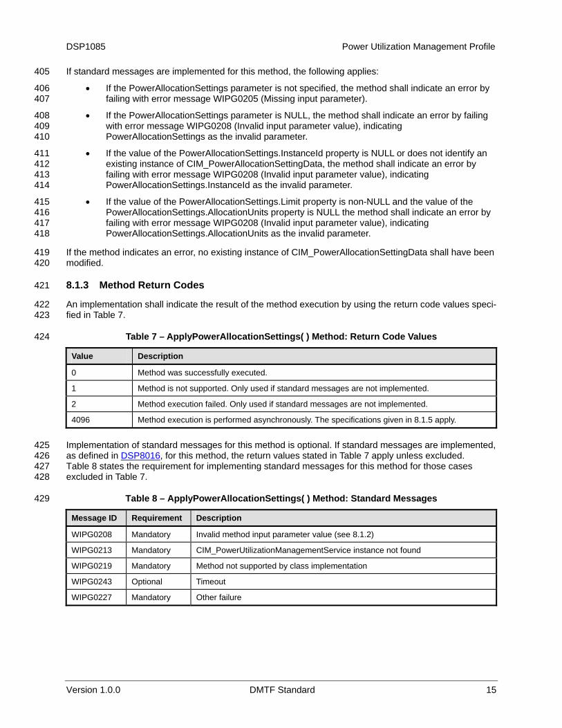
If standard messages are implemented for this method, the following applies: 405
406 407
408 409 410
411 412 413 414
415 416 417 418
419 420
422 423
424
• If the PowerAllocationSettings parameter is not specified, the method shall indicate an error by failing with error message WIPG0205 (Missing input parameter).
• If the PowerAllocationSettings parameter is NULL, the method shall indicate an error by failing with error message WIPG0208 (Invalid input parameter value), indicating PowerAllocationSettings as the invalid parameter.
• If the value of the PowerAllocationSettings.InstanceId property is NULL or does not identify an existing instance of CIM_PowerAllocationSettingData, the method shall indicate an error by failing with error message WIPG0208 (Invalid input parameter value), indicating PowerAllocationSettings.InstanceId as the invalid parameter.
• If the value of the PowerAllocationSettings.Limit property is non-NULL and the value of the PowerAllocationSettings.AllocationUnits property is NULL the method shall indicate an error by failing with error message WIPG0208 (Invalid input parameter value), indicating PowerAllocationSettings.AllocationUnits as the invalid parameter.
If the method indicates an error, no existing instance of CIM_PowerAllocationSettingData shall have been modified.
8.1.3 Method Return Codes 421
An implementation shall indicate the result of the method execution by using the return code values speci-fied in Table 7.
Table 7 – ApplyPowerAllocationSettings( ) Method: Return Code Values
Value Description
0 Method was successfully executed.
1 Method is not supported. Only used if standard messages are not implemented.
2 Method execution failed. Only used if standard messages are not implemented.
4096 Method execution is performed asynchronously. The specifications given in 8.1.5 apply.
Implementation of standard messages for this method is optional. If standard messages are implemented, as defined in
425 DSP8016, for this method, the return values stated in Table 7 apply unless excluded. 426
427 428
429
Table 8 states the requirement for implementing standard messages for this method for those cases excluded in Table 7.
Table 8 – ApplyPowerAllocationSettings( ) Method: Standard Messages
Message ID Requirement Description
WIPG0208 Mandatory Invalid method input parameter value (see 8.1.2)
WIPG0213 Mandatory CIM_PowerUtilizationManagementService instance not found
WIPG0219 Mandatory Method not supported by class implementation
WIPG0243 Optional Timeout
WIPG0227 Mandatory Other failure

Power Utilization Management Profile DSP1085
16 DMTF Standard Version 1.0.0
8.1.4 Method Results 430
If the implementation does not support a method, it shall set a return value of 1 (Not Supported). 431
432 433
434 435
436 437
438
439 440
441 442
443
444 445
446 447
449 450
452 453
454 455
456 457
If synchronous execution of a method succeeds, the implementation shall set a return value of 0 (Completed with No Error).
If synchronous execution of a method fails, the implementation shall set a return value of 2 (Error Occurred).
If a method is executed as an asynchronous task, the implementation shall perform all of the following actions:
• Set a return value of 4096 (Job Started).
• Set the value of the Job output parameter to refer to an instance of the CIM_ConcreteJob class that represents the asynchronous task.
• Set the values of the JobState and TimeOfLastStateChange properties in that instance to repre-sent the state and last state change time of the asynchronous task.
In addition, the implementation may present state change indications as task state changes occur.
If the method execution as an asynchronous task succeeds, the implementation shall perform all of the following actions:
If the method execution as an asynchronous task fails, the implementation shall set the value of the JobState property to 9 (Killed) or 10 (Exception).
8.1.5 Asynchronous Processing 448
An implementation may support asynchronous processing of the ApplyPowerAllocationsSettings method specified in the CIM_PowerUtilizationManagementService class.
8.1.5.1 Job Parameter 451
The implementation shall set the value of the Job parameter as a result of an asynchronous execution of a method of the CIM_PowerUtilizationManagementService as follows:
• If the method execution is performed synchronously, the implementation shall set the value to NULL.
• If the method execution is performed asynchronously, the implementation shall set the value to refer to the instance of the CIM_ConcreteJob class that represents the asynchronous task.
8.2 Profile Conventions for Operations 458
This profile defines intrinsic operations in terms of DSP0200. For each profile class (including associations), the implementation requirements for operations, including those in the following default list, are specified in class-specific subclauses of this clause. The default list of operations is as follows:
459 460 461
462 463 464
465 466
467 468 469
GetInstance( ) EnumerateInstances( ) EnumerateInstanceNames( )
For classes that are referenced by an association, the default list of operations includes the following operations in addition:
Associators( ) AssociatorNames( ) References( )
DSP1085 Power Utilization Management Profile
Version 1.0.0 DMTF Standard 17
ReferenceNames( ) 470
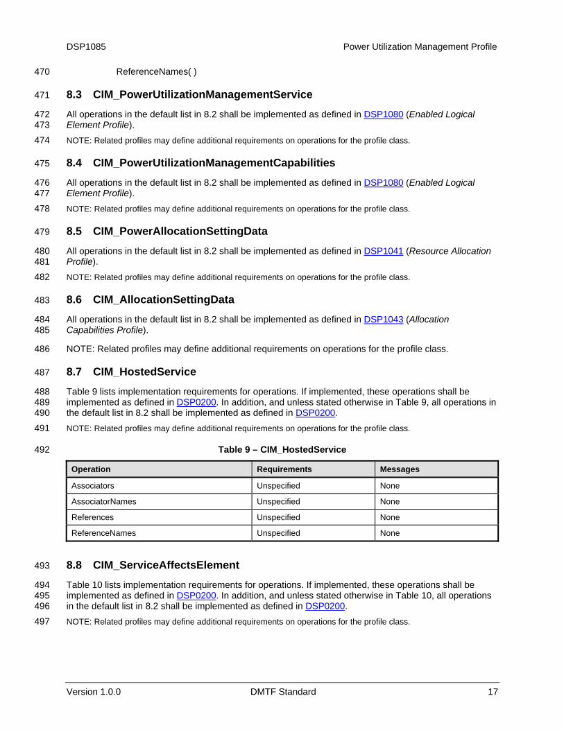
8.3 CIM_PowerUtilizationManagementService 471
All operations in the default list in 8.2 shall be implemented as defined in DSP1080 (Enabled Logical Element Profile).
472 473 474 NOTE: Related profiles may define additional requirements on operations for the profile class.
8.4 CIM_PowerUtilizationManagementCapabilities 475
All operations in the default list in 8.2 shall be implemented as defined in DSP1080 (Enabled Logical Element Profile).
476 477 478 NOTE: Related profiles may define additional requirements on operations for the profile class.
8.5 CIM_PowerAllocationSettingData 479
All operations in the default list in 8.2 shall be implemented as defined in DSP1041 (Resource Allocation Profile).
480 481 482 NOTE: Related profiles may define additional requirements on operations for the profile class.
8.6 CIM_AllocationSettingData 483
All operations in the default list in 8.2 shall be implemented as defined in DSP1043 (Allocation Capabilities Profile).
484 485
486
488
NOTE: Related profiles may define additional requirements on operations for the profile class.
8.7 CIM_HostedService 487
Table 9 lists implementation requirements for operations. If implemented, these operations shall be implemented as defined in DSP0200. In addition, and unless stated otherwise in Table 9, all operations in the default list in
489 8.2 shall be implemented as defined in DSP0200. 490
491
492
NOTE: Related profiles may define additional requirements on operations for the profile class.
Table 9 – CIM_HostedService
Operation Requirements Messages
Associators Unspecified None
AssociatorNames Unspecified None
References Unspecified None
ReferenceNames Unspecified None
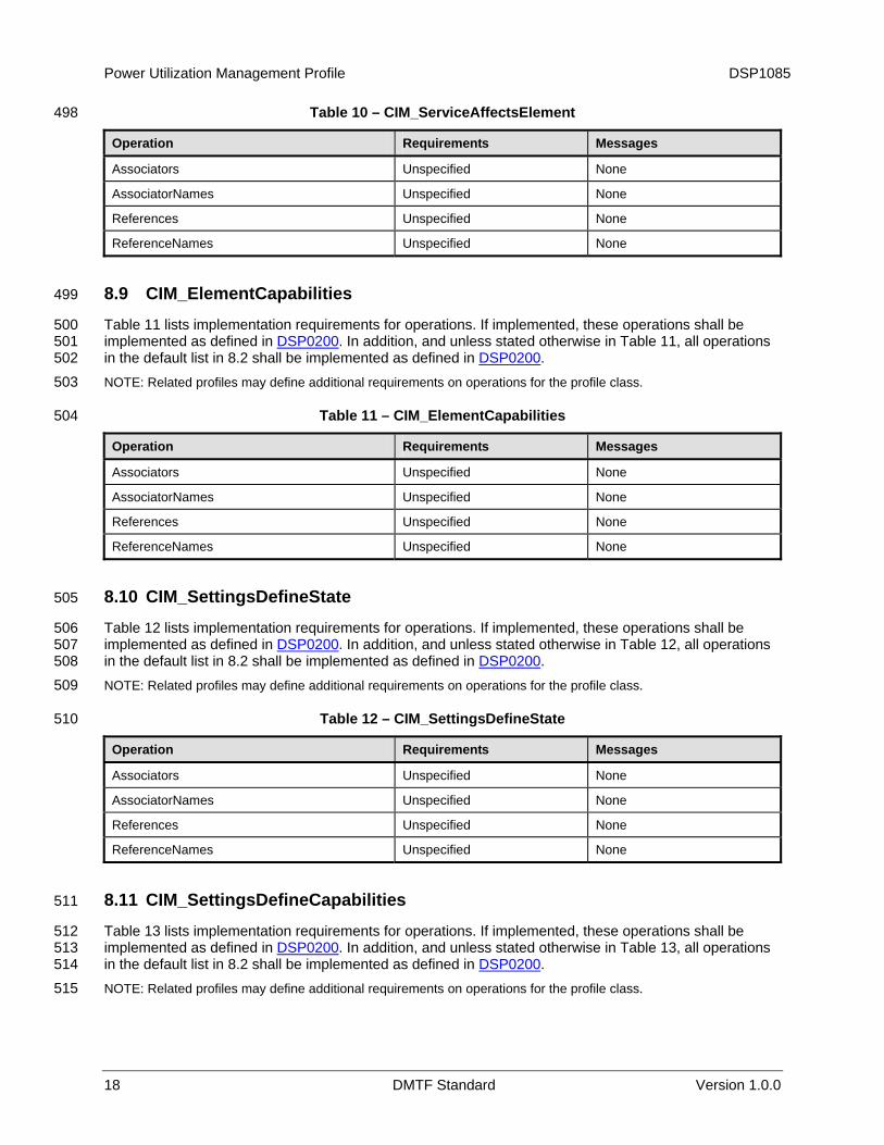
8.8 CIM_ServiceAffectsElement 493
Table 10 lists implementation requirements for operations. If implemented, these operations shall be implemented as defined in
494 DSP0200. In addition, and unless stated otherwise in Table 10, all operations
in the default list in 495
8.2 shall be implemented as defined in DSP0200. 496 497 NOTE: Related profiles may define additional requirements on operations for the profile class.
Power Utilization Management Profile DSP1085
18 DMTF Standard Version 1.0.0
Table 10 – CIM_ServiceAffectsElement 498
Operation Requirements Messages
Associators Unspecified None
AssociatorNames Unspecified None
References Unspecified None
ReferenceNames Unspecified None
8.9 CIM_ElementCapabilities 499
Table 11 lists implementation requirements for operations. If implemented, these operations shall be implemented as defined in
500 DSP0200. In addition, and unless stated otherwise in Table 11, all operations
in the default list in 501
8.2 shall be implemented as defined in DSP0200. 502 503
504
NOTE: Related profiles may define additional requirements on operations for the profile class.
Table 11 – CIM_ElementCapabilities
Operation Requirements Messages
Associators Unspecified None
AssociatorNames Unspecified None
References Unspecified None
ReferenceNames Unspecified None
8.10 CIM_SettingsDefineState 505
Table 12 lists implementation requirements for operations. If implemented, these operations shall be implemented as defined in
506 DSP0200. In addition, and unless stated otherwise in Table 12, all operations
in the default list in 507
8.2 shall be implemented as defined in DSP0200. 508 509
510
NOTE: Related profiles may define additional requirements on operations for the profile class.
Table 12 – CIM_SettingsDefineState
Operation Requirements Messages
Associators Unspecified None
AssociatorNames Unspecified None
References Unspecified None
ReferenceNames Unspecified None
8.11 CIM_SettingsDefineCapabilities 511
Table 13 lists implementation requirements for operations. If implemented, these operations shall be implemented as defined in
512 DSP0200. In addition, and unless stated otherwise in Table 13, all operations
in the default list in 513
8.2 shall be implemented as defined in DSP0200. 514 515 NOTE: Related profiles may define additional requirements on operations for the profile class.

DSP1085 Power Utilization Management Profile
Version 1.0.0 DMTF Standard 19
Table 13 – CIM_SettingsDefineCapabilities 516
Operation Requirements Messages
Associators Unspecified None
AssociatorNames Unspecified None
References Unspecified None
ReferenceNames Unspecified None
8.12 CIM_ElementCapabilities 517
Table 14 lists implementation requirements for operations. If implemented, these operations shall be implemented as defined in
518 DSP0200. In addition, and unless stated otherwise in Table 14, all operations
in the default list in 519
8.2 shall be implemented as defined in DSP0200. 520 521
522
NOTE: Related profiles may define additional requirements on operations for the profile class.
Table 14 – CIM_ElementCapabilities
Operation Requirements Messages
Associators Unspecified None
AssociatorNames Unspecified None
References Unspecified None
ReferenceNames Unspecified None
8.13 CIM_ElementConformsToProfile 523
Table 15 lists implementation requirements for operations. If implemented, these operations shall be implemented as defined in
524 DSP0200. In addition, and unless stated otherwise in Table 15, all operations
in the default list in 525
8.2 shall be implemented as defined in DSP0200. 526 527
528
NOTE: Related profiles may define additional requirements on operations for the profile class.
Table 15 – CIM_ElementConformsToProfile
Operation Requirements Messages
Associators Unspecified None
AssociatorNames Unspecified None
References Unspecified None
ReferenceNames Unspecified None
9 Use Cases 529
This clause contains object diagrams and use cases for the Power Utilization Management Profile. 530
532 533
9.1 Object Diagrams 531
This subclause contains object diagrams for the Power State Management Profile. For simplicity, the prefix CIM_ has been removed from the names of the classes in the diagrams.
Power Utilization Management Profile DSP1085
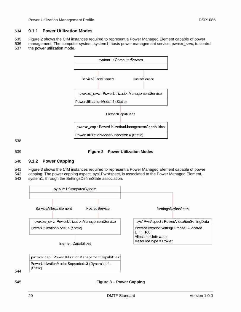
9.1.1 Power Utilization Modes 534
535 536 537
Figure 2 shows the CIM instances required to represent a Power Managed Element capable of power management. The computer system, system1, hosts power management service, pwrexr_srvc, to control the power utilization mode.
538
539
541 542 543
Figure 2 – Power Utilization Modes
9.1.2 Power Capping 540
Figure 3 shows the CIM instances required to represent a Power Managed Element capable of power capping. The power capping aspect, sys1PwrAspect, is associated to the Power Managed Element, system1, through the SettingsDefineState association.
544
545 Figure 3 – Power Capping
20 DMTF Standard Version 1.0.0
DSP1085 Power Utilization Management Profile
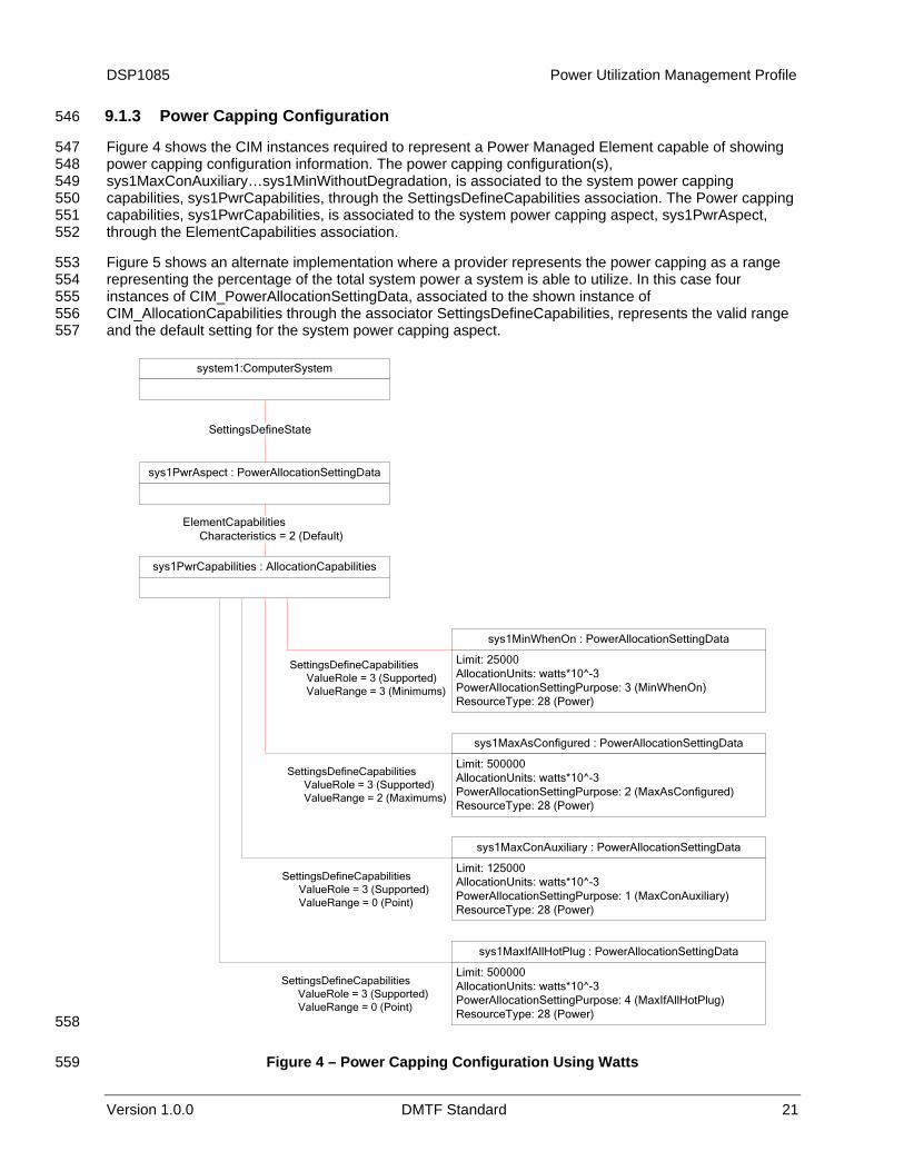
9.1.3 Power Capping Configuration 546
547 548 549 550 551 552
553 554 555 556 557
Figure 4 shows the CIM instances required to represent a Power Managed Element capable of showing power capping configuration information. The power capping configuration(s), sys1MaxConAuxiliary…sys1MinWithoutDegradation, is associated to the system power capping capabilities, sys1PwrCapabilities, through the SettingsDefineCapabilities association. The Power capping capabilities, sys1PwrCapabilities, is associated to the system power capping aspect, sys1PwrAspect, through the ElementCapabilities association.
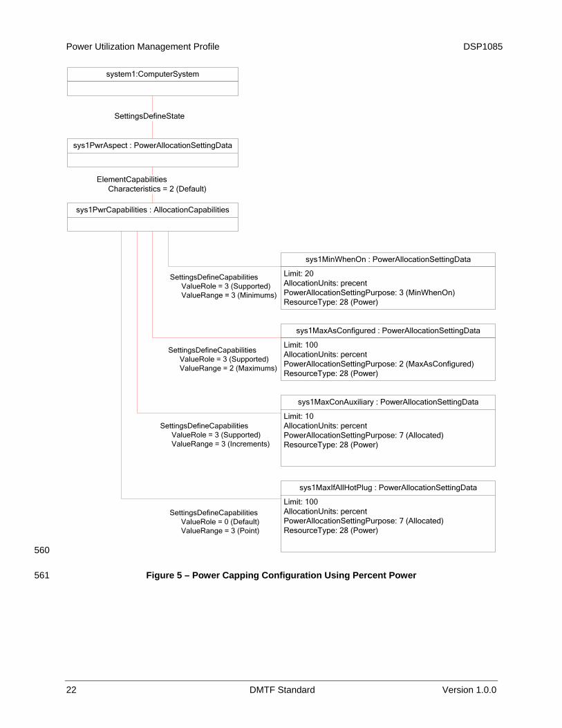
Figure 5 shows an alternate implementation where a provider represents the power capping as a range representing the percentage of the total system power a system is able to utilize. In this case four instances of CIM_PowerAllocationSettingData, associated to the shown instance of CIM_AllocationCapabilities through the associator SettingsDefineCapabilities, represents the valid range and the default setting for the system power capping aspect.
system1:ComputerSystem
sys1PwrAspect : PowerAllocationSettingData
SettingsDefineState
sys1PwrCapabilities : AllocationCapabilities
ElementCapabilitiesCharacteristics = 2 (Default)
sys1MinWhenOn : PowerAllocationSettingData
Limit: 25000AllocationUnits: watts*10^-3PowerAllocationSettingPurpose: 3 (MinWhenOn)ResourceType: 28 (Power)
sys1MaxAsConfigured : PowerAllocationSettingData
Limit: 500000AllocationUnits: watts*10^-3PowerAllocationSettingPurpose: 2 (MaxAsConfigured)ResourceType: 28 (Power)
sys1MaxIfAllHotPlug : PowerAllocationSettingData
Limit: 500000AllocationUnits: watts*10^-3PowerAllocationSettingPurpose: 4 (MaxIfAllHotPlug)ResourceType: 28 (Power)
sys1MaxConAuxiliary : PowerAllocationSettingData
Limit: 125000AllocationUnits: watts*10^-3PowerAllocationSettingPurpose: 1 (MaxConAuxiliary)ResourceType: 28 (Power)
SettingsDefineCapabilitiesValueRole = 3 (Supported)ValueRange = 3 (Minimums)
SettingsDefineCapabilitiesValueRole = 3 (Supported)ValueRange = 2 (Maximums)
SettingsDefineCapabilitiesValueRole = 3 (Supported)ValueRange = 0 (Point)
SettingsDefineCapabilitiesValueRole = 3 (Supported)ValueRange = 0 (Point)
558
559 Figure 4 – Power Capping Configuration Using Watts
Version 1.0.0 DMTF Standard 21
Power Utilization Management Profile DSP1085
system1:ComputerSystem
sys1PwrAspect : PowerAllocationSettingData
SettingsDefineState
sys1PwrCapabilities : AllocationCapabilities
ElementCapabilitiesCharacteristics = 2 (Default)
sys1MinWhenOn : PowerAllocationSettingData
Limit: 20AllocationUnits: precentPowerAllocationSettingPurpose: 3 (MinWhenOn)ResourceType: 28 (Power)
sys1MaxAsConfigured : PowerAllocationSettingData
Limit: 100AllocationUnits: percentPowerAllocationSettingPurpose: 2 (MaxAsConfigured)ResourceType: 28 (Power)
sys1MaxIfAllHotPlug : PowerAllocationSettingData
Limit: 100AllocationUnits: percentPowerAllocationSettingPurpose: 7 (Allocated)ResourceType: 28 (Power)
sys1MaxConAuxiliary : PowerAllocationSettingData
Limit: 10AllocationUnits: percentPowerAllocationSettingPurpose: 7 (Allocated)ResourceType: 28 (Power)
SettingsDefineCapabilitiesValueRole = 3 (Supported)ValueRange = 3 (Minimums)
SettingsDefineCapabilitiesValueRole = 3 (Supported)ValueRange = 2 (Maximums)
SettingsDefineCapabilitiesValueRole = 3 (Supported)ValueRange = 3 (Increments)
SettingsDefineCapabilitiesValueRole = 0 (Default)ValueRange = 3 (Point)
560
561 Figure 5 – Power Capping Configuration Using Percent Power
22 DMTF Standard Version 1.0.0

DSP1085 Power Utilization Management Profile
Version 1.0.0 DMTF Standard 23
9.2 Find the Power Utilization Management Service for a Power Managed 562 Element 563
564
565 566
568 569
570 571
572 573
575
576 577 578 579
581
582 583 584
585
587
588 589
590 591 592
593 594 595 596
A client can find the power management service for a Power Managed Element as follows:
For the Power Managed Element enumerate the instances of the ServiceAffectsElement association and identify the instance that associates the instance of CIM_PowerUtilizationManagementService.
9.3 Determining If State Management Is Supported 567
For a given instance of CIM_PowerUtilizationManagementService, a client can determine whether state management is supported as follows:
1) Find the CIM_PowerUtilizationManagementCapabilities instance that is associated with the instance.
2) Query the value of the RequestedStatesSupported property. If at least one value is specified, state management is supported.
9.4 Determine the Power Utilization Mode in use by a Power Managed Element 574
A client can determine the power state of the Power Managed Element as follows:
For the Power Managed Element enumerate the instances of the CIM_ServiceAffectsElement association and identify the instance that associates the instance of CIM_PowerUtilizationManagementService. The PowerSavingsMode property of the CIM_PowerUtilizationManagementService represents the power utilization modes.
9.5 Change the Power Utilization Mode of a Power Managed Element 580
A client can change the power utilization mode of the Power Managed Element as follows:
1) For the Power Managed Element enumerate the instances of the CIM_ServiceAffectsElement association and identify the instance that associates the instance of CIM_PowerUtilizationManagementService.
2) Change the value of the PowerSavingsMode property to the appropriate mode.
9.6 Determine the Power Utilization Modes Supported by a Power Managed 586 Element
A client can determine whether power utilization modes are supported for a Power Managed Element as follows:
1) Navigate from the target instance of CIM_ManagedSystemElement to the instance of CIM_PowerUtilizationManagementService that represents the service that manages that system by using the CIM_ServiceAffectsElement association.
2) Using the instance of CIM_PowerUtilizationManagementService, navigate to the instance of CIM_PowerUtilizationManagementCapabilities through the CIM_ElementCapabilities association. The PowerUtilizationModesSupported property array contains the modes supported.

Power Utilization Management Profile DSP1085
24 DMTF Standard Version 1.0.0
9.7 Determine Whether Power Capping Is Supported by a Power Managed 597 Element 598
599 600
601 602 603
604 605 606
608 609
610 611 612
613
615 616
617 618 619
620 621 622 623
625
626 627
628 629 630
631 632 633
634 635 636
A client can determine whether power utilization modes are supported for a Power Managed Element as follows:
1) From the instance of CIM_ManagedSystemElement that represents the Power Managed Element, identify the instance of CIM_PowerUtilizationManagementService associated via an instance of CIM_ServiceAffectsElement.
2) From the instance of CIM_PowerUtilizationManagementService, find the instance of CIM_PowerUtilizationManagementCapabilities associated via CIM_ElementCapabilities. Evalute the SupportedMethods property to determine if the power capping is supported.
9.8 Determine the Power Capping value for a Power Managed Element 607
Select the instance of CIM_PowerAllocationSettingData that represents the power capping aspect of the Power Managed Element.
1) From the instance of CIM_ManagedSystemElement that represents the Power Managed Element identify the instance of CIM_PowerAllocationSettingData associated via an instance of CIM_SettingsDefineState.
2) The Limit property of the instance so found represents the current capping value.
9.9 Change the Power Capping value for a Power Managed Element 614
Select the instance of CIM_PowerAllocationSettingData that represents the power capping aspect of the Power Managed Element.
1) From the instance of CIM_ManagedSystemElement that represents the Power Managed Element identify the instance of CIM_PowerAllocationSettingData associated via an instance of CIM_SettingsDefineState.
2) Using ApplyPowerAllocationSettings method with an embedded instance parameter of PowerAllocationSettingData that has its limit and AllocationUnits properties set to the appropriate value change the power capping of the system. See 9.10 and 9.11 in determining the supported AllocationUnits.
9.10 Determine the Power Capping Configuration Parameters for a Power 624 Managed Element Expressed in Watts
A client can determine whether watts of power utilization are supported and valid configuration parameters for a Power Managed Element as follows:
1) From the instance of CIM_ManagedSystemElement that represents the Power Managed Element, identify the instance of CIM_PowerAllocationSettingData associated via an instance of CIM_SettingsDefineState.
2) From the instance of CIM_PowerAllocationSettingData find the instance(s) of CIM_AllocationCapabilities.that are each associated via an instance of CIM_ElementCapabilities.
3) Find all instances of CIM_PowerAllocationSettingData associated to the instance(s) of CIM_AllocationCapabilities through CIM_SettingsDefineCapabilities association where the AllocationUnit property is equal to “Watts.”
4) Evaluate, as described in DSP1043 (AllocationCapabilities Profile) the set of instances so found in step three to determine the valid range and any supported point settings for the power capping configuration parameters.
637 638 639

DSP1085 Power Utilization Management Profile
Version 1.0.0 DMTF Standard 25
9.11 Determine the Power Capping Configuration Parameters for a Power 640 Managed Element Expressed as a Range of Percentages 641
642 643
644 645 646
647 648 649
650 651 652
A client can determine whether percentage of power utilization is supported and valid configuration parameters for a Power Managed Element as follows:
1) From the instance of CIM_ManagedSystemElement that represents the Power Managed Element, identify the instance of CIM_PowerAllocationSettingData associated via an instance of CIM_SettingsDefineState.
2) From the instance of CIM_PowerAllocationSettingData find the instance(s) of CIM_AllocationCapabilities.that are each associated via an instance of CIM_ElementCapabilities.
3) Find all instances of CIM_PowerAllocationSettingData associated to the instance(s) of CIM_AllocationCapabilities through CIM_SettingsDefineCapabilities association where the AllocationUnit property is equal to “Percent.”
4) Evaluate, as described in DSP1043 (AllocationCapabilities Profile) the set of instances so found in step three to determine the valid range and any supported point settings for the power capping configuration parameters.
653 654 655
657 658 659
660
10 CIM Elements 656
Table 16 shows the instances of CIM Elements for this profile. Instances of the CIM Elements shall be implemented as described in Table 16. Clauses 7 (“Implementation Requirements”) and 8 (“Methods”) may impose additional requirements on these elements.
Table 16 – CIM Elements: Power Utilization Management Profile
Element Name Requirement Description
Classes
CIM_PowerUtilizationManagementService Mandatory See 7.1 and 10.1.
CIM_PowerUtilizationManagementCapabilities Mandatory See 7.1.2 and 10.2.
CIM_ServiceAffectsElement Mandatory See 10.3.
CIM_HostedService Mandatory See 10.4.
CIM_ElementCapabilities (CIM_PowerUtilizationManagementService) Mandatory See 10.5.
CIM_PowerAllocationSettingData (CIM_ManagedSystemElement) Optional See 7.2 and 10.6.
CIM_SettingsDefineState Conditional See 10.7.
CIM_AllocationCapabilities Optional See 10.8.
CIM_ElementCapabilities (CIM_AllocationCapabilities) Conditional See 10.9.
CIM_PowerAllocationSettingData (CIM_AllocationCapabilities) Conditional See 7.3 and 10.10.
CIM_SettingsDefineCapabilities Conditional See 10.11.
CIM_RegisteredProfile Mandatory See 10.12.
Indications
None defined in this profile

Power Utilization Management Profile DSP1085
26 DMTF Standard Version 1.0.0
10.1 CIM_PowerUtilizationManagementService 661
CIM_PowerUtilizationManagementService represents the power utilization management service responsible for controlling the power utilization mode of a Power Managed Element.
662 663 664 665
Table 17 contains the requirements for elements of this class. The constraints specified for CIM_PowerUtilizationManagementService are in addition to those specified for CIM_EnabledLogicalElement in the Enabled Logical Element Profile. 666
667 Table 17 – Class: CIM_PowerUtilizationManagementService
Properties Requirement Notes
CreationClassName Mandatory Key
Name Mandatory Key
PowerUtilizationMode Mandatory
EnabledState Mandatory See 7.1.1.1.1.
RequestedState Mandatory See 7.1.1.1.2.
ApplyPowerAllocationSettings( ) Conditional See 8.1.1.
10.2 CIM_PowerUtilizationManagementCapabilities 668
CIM_PowerUtilizationManagementCapabilities represents the power utilization modes capabilities of a Power Managed Element.
669 Table 18 contains the requirements for elements of this class. See DSP1080
for further requirements. 670 671
672 Table 18 – Class: CIM_PowerUtilizationManagementCapabilities
Properties Requirement Notes
InstanceID Mandatory Key
PowerUtilizationModesSupported Mandatory
SupportedMethods Mandatory
10.3 CIM_ServiceAffectsElement 673
CIM_ServiceAffectsElement associates the CIM_ManagedSystemElement instance that represents the target Power Managed Element with the CIM_PowerUtilizationManagementService instance that represents the service responsible for controlling the power utilization modes of a Power Managed Element.
674 675 676 677 Table 19 contains the requirements for elements of this class.
DSP1085 Power Utilization Management Profile
Version 1.0.0 DMTF Standard 27
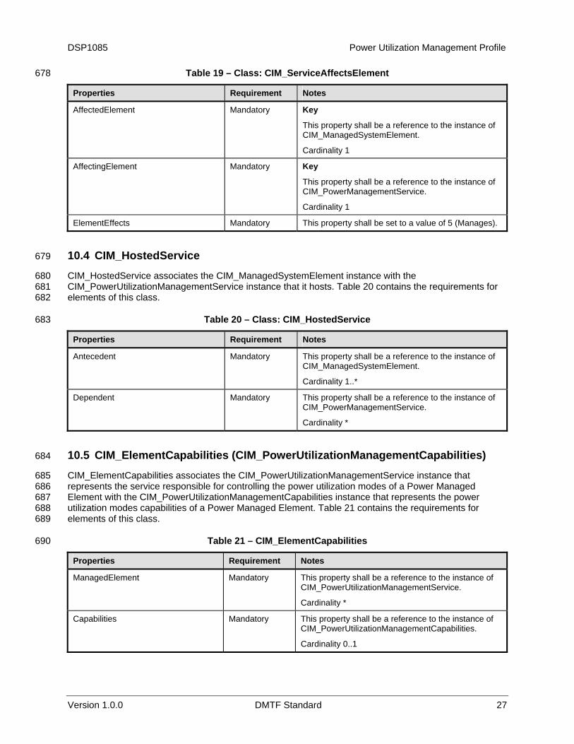
Table 19 – Class: CIM_ServiceAffectsElement 678
Properties Requirement Notes
AffectedElement Mandatory Key
This property shall be a reference to the instance of CIM_ManagedSystemElement.
Cardinality 1
AffectingElement Mandatory Key
This property shall be a reference to the instance of CIM_PowerManagementService.
Cardinality 1
ElementEffects Mandatory This property shall be set to a value of 5 (Manages).
10.4 CIM_HostedService 679
CIM_HostedService associates the CIM_ManagedSystemElement instance with the CIM_PowerUtilizationManagementService instance that it hosts.
680 681 682
683
Table 20 contains the requirements for elements of this class.
Table 20 – Class: CIM_HostedService
Properties Requirement Notes
Antecedent Mandatory This property shall be a reference to the instance of CIM_ManagedSystemElement.
Cardinality 1..*
Dependent Mandatory This property shall be a reference to the instance of CIM_PowerManagementService.
Cardinality *
10.5 CIM_ElementCapabilities (CIM_PowerUtilizationManagementCapabilities) 684
CIM_ElementCapabilities associates the CIM_PowerUtilizationManagementService instance that represents the service responsible for controlling the power utilization modes of a Power Managed Element with the CIM_PowerUtilizationManagementCapabilities instance that represents the power utilization modes capabilities of a Power Managed Element.
685 686 687 688 689
690
Table 21 contains the requirements for elements of this class.
Table 21 – CIM_ElementCapabilities
Properties Requirement Notes
ManagedElement Mandatory This property shall be a reference to the instance of CIM_PowerUtilizationManagementService.
Cardinality *
Capabilities Mandatory This property shall be a reference to the instance of CIM_PowerUtilizationManagementCapabilities.
Cardinality 0..1

Power Utilization Management Profile DSP1085
28 DMTF Standard Version 1.0.0
10.6 CIM_PowerAllocationSettingData (CIM_ManagedSystemElement) 691
CIM_PowerAllocationSettingData instance represents the power capping aspect of a Power Managed Element.
692 693
694
Table 22 contains the requirements for the elements of this class.
Table 22 – CIM_PowerAllocationSettingData
Properties Requirement Notes
InstanceID Mandatory Key
ElementName Mandatory
ResourceType Mandatory This property shall be set to a value of 28 (Power).
AllocationUnits Mandatory
Limit Mandatory This property shall be represent the power capping (see 7.2)
10.7 CIM_SettingsDefineState 695
CIM_SettingsDefineState instance associates the CIM_ManagedSystemElement instance, which represents the target Power Managed Element, with the CIM_PowerAllocationSettingData instance, which represents the power capping aspect of the target Power Managed Element.
696 697 698 699
700
Table 23 contains the requirements for elements of this class.
Table 23 – CIM_SettingDefinesState
Properties Requirement Notes
ManagedElement Mandatory This property shall be a reference to the instance of CIM_ManagedSystemElement.
Cardinality 1
SettingData Mandatory This property shall be a reference to the instance of CIM_PowerAllocationSettingData.
Cardinality 1
10.8 CIM_AllocationCapabilities 701
CIM_AllocationCapabilities instance represents the type of the allocation capabilities reported by the Power Managed Element.
702 703 704 705
706
Table 24 contains the requirements for the elements of this class. The constraints defined in Table 24 are in addition to those placed on CIM_AllocationCapabilities in the Allocation Capabilities Profile.
Table 24 – CIM_AllocationCapabilities
Properties Requirement Notes
InstanceID Mandatory Key
ElementName Mandatory
ResourceType Mandatory This property shall be set to a value of 28 (Power).
DSP1085 Power Utilization Management Profile
Version 1.0.0 DMTF Standard 29
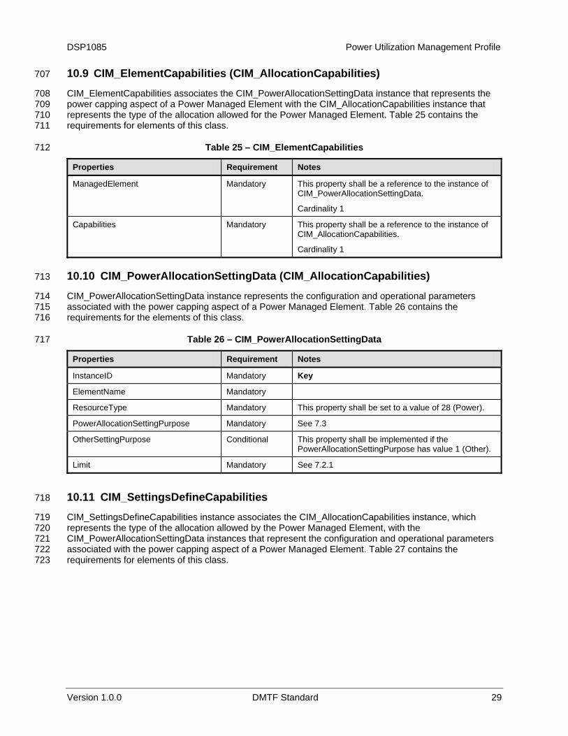
10.9 CIM_ElementCapabilities (CIM_AllocationCapabilities) 707
CIM_ElementCapabilities associates the CIM_PowerAllocationSettingData instance that represents the power capping aspect of a Power Managed Element with the CIM_AllocationCapabilities instance that represents the type of the allocation allowed for the Power Managed Element.
708 709 710 711
712
Table 25 contains the requirements for elements of this class.
Table 25 – CIM_ElementCapabilities
Properties Requirement Notes
ManagedElement Mandatory This property shall be a reference to the instance of CIM_PowerAllocationSettingData.
Cardinality 1
Capabilities Mandatory This property shall be a reference to the instance of CIM_AllocationCapabilities.
Cardinality 1
10.10 CIM_PowerAllocationSettingData (CIM_AllocationCapabilities) 713
CIM_PowerAllocationSettingData instance represents the configuration and operational parameters associated with the power capping aspect of a Power Managed Element.
714 715 716
717
Table 26 contains the requirements for the elements of this class.
Table 26 – CIM_PowerAllocationSettingData
Properties Requirement Notes
InstanceID Mandatory Key
ElementName Mandatory
ResourceType Mandatory This property shall be set to a value of 28 (Power).
PowerAllocationSettingPurpose Mandatory See 7.3
OtherSettingPurpose Conditional This property shall be implemented if the PowerAllocationSettingPurpose has value 1 (Other).
Limit Mandatory See 7.2.1
10.11 CIM_SettingsDefineCapabilities 718
CIM_SettingsDefineCapabilities instance associates the CIM_AllocationCapabilities instance, which represents the type of the allocation allowed by the Power Managed Element, with the CIM_PowerAllocationSettingData instances that represent the configuration and operational parameters associated with the power capping aspect of a Power Managed Element.
719 720 721 722 723
Table 27 contains the requirements for elements of this class.

Power Utilization Management Profile DSP1085
30 DMTF Standard Version 1.0.0
Table 27 – CIM_SettingsDefineCapabilities 724
Properties Requirement Notes
GroupComponent Mandatory This property shall be a reference to the instance of CIM_AllocationCapabilities.
Cardinality 1
PartComponent Mandatory This property shall be a reference to the instances of CIM_PowerAllocationSettingData.
Cardinality 1
10.12 CIM_RegisteredProfile 725
CIM_RegisteredProfile is defined by the Profile Registration Profile. The requirements denoted in 726 Table 28 are in addition to those mandated by the Profile Registration Profile. 727
728 Table 28 – Class: CIM_RegisteredProfile
Properties Requirement Notes
RegisteredName Mandatory This property shall have a value of “Power Utilization Management”.
RegisteredValue Mandatory This property shall have a value of “1.0.0”.
RegisteredOrganization Mandatory This property shall have a value of 2 (DMTF).

DSP1085 Power Utilization Management Profile
Version 1.0.0 DMTF Standard 31
ANNEX A (Informative)
Change Log
729 730 731 732
Version Date Description
1.0.0 01/12/2010 DMTF Standard Release
733