Embed Size (px)
Citation preview

International Journal of Advanced Technology in Engineering and Science www.ijates.com
Volume No.02, Issue No. 11, November 2014 ISSN (online): 2348 – 7550
401 | P a g e
POWER TRANSMISSION FROM OFFSHORE WIND
ENERGY FOR LOW-FREQUENCY
Anamala Tulasi Ram1, R.Jagadeesh Nethra
2, M.Venkateswara Reddy
3
1PG Student,
2,3Assistant Professor
Department of EEE, Vikas Group of Institutions, Nunna, Vijayawada, A.P, (India)
ABSTRACT
The limitations of an A transmission system for long distances are presented together with the advantages of a
HVDC transmission system. The power system under study includes an offshore wind farm comprising turbines
equipped with full range converters. The collection network is a local AC grid. Power transmission is done
through HVDC system. The integration of offshore wind farms with the main power grid is a major issue. The
possible solutions for transmitting power from wind farms are HVAC, Line commutated HVDC and voltage
source based HVDC (VSCHVDC). In this paper Low Frequency AC (LFAC) transmission system is used for
interconnecting the offshore wind farms for improving the transmission capability and also the dc collecting
system with series connected wind turbines are used at the offshore to reduce the cabling requirement.
Simulations are performed using MATLAB/SIMULINK to illustrate the system’s performance.
Index Terms—Power Transmission, Thyristor Converters, Underwater Power Cables, Wind Energy
I. INTRODUCTION
The increasing interest and gradual necessity of using renewable resources, such as wind, solar and hydro
energy, have brought about strong demands for economic and technical innovation and development. Especially
offshore wind farms are expected to represent a significant component of the future electric generation selection
due to larger space availability and better wind energy potential in offshore locations. In particular, both the
interconnection and transmission of renewable resources into synchronous grid systems have become promising
topics to power engineers. For robust and reliable transmission and interconnection of renewable energy into
central grid system switching systems have been used, Since switching systems can easily permit excellent
controllability of electrical signals such as changing voltage and frequency levels, and power factors. At present,
high-voltage ac (HVAC) and high-voltage dc (HVDC) are well-known technologies for transmission [1-3].
HVAC transmission is advantageous because it is somewhat simple to design the protection system and to
change voltage levels using transformers. However, the substantial charging current due to the high capacitance
of submarine ac power cables reduces the active power transmission capacity and limits the transmission
distance.
Therefore HVAC is adopted for relatively short underwater transmission distances. HVAC is applied for
distances less than 60km for offshore wind power transmission. Two classes of HVDC systems exist, depending
on the types of power-electronic devices used: 1) line-commutated converter HVDC (LCC-HVDC) using
thyristors and 2) voltage-source converter HVDC (VSC-HVDC) using self commutated devices, for example,
insulated-gate bipolar transistors (IGBTs) [4]. The major advantage of HVDC technology is that it imposes
International Journal of Advanced Technology in Engineering and Science www.ijates.com
Volume No.02, Issue No. 11, November 2014 ISSN (online): 2348 – 7550
402 | P a g e
effectively no limit on transmission distance due to the absence of reactive current in the transmission line.
LCC-HVDC systems can transmit power up to 1GW with high reliability [1]. The reduced efficiency and cost of
the converters are the drawbacks of VSCHVDC systems. Power levels and reliability are lower than those of
LCC-HVDC. HVDC is applied for distances greater than 100 km for offshore wind power transmission. In
addition HVAC and HVDC, high-voltage low frequency ac (LFAC) transmission has been recently proposed [8-
9]. In LFAC systems, an intermediate frequency level 16.66 or 20Hz is used, which is created by using a cyclo
converter that lowers the grid frequency to a smaller value, normally to one-third its value.
In this paper, a novel LFAC transmission topology is analyzed. The proposed system differs from previous work
in that the wind turbines are assumed to be inter connected with a medium-voltage (MV) dc grid, in contrast
with current practice, where the use of MV a collection grids is standard. DC collection is becoming a feasible
alternative with the development of cost-effective and reliable dc circuit breakers, and studies have shown that it
might be advantageous with respect to ac collection in terms of efficiency and improved production costs. The
required dc voltage level can be built by using high-power dc–dc converters and/or by the series connection of
wind turbines. For example, multi-MW permanent-magnet synchronous generators with fully rated power
converters (Type-4 turbines) are commonly used in offshore wind plants. By eliminating grid-side inverters, a
medium-voltage dc collection system can be formed by interconnecting the rectified output of the generators.
The main reason for using a dc collection system with LFAC transmission is that the wind turbines would not
need to be redesigned to output low-frequency ac power, which would lead to larger, heavier, and costlier
magnetic components (e.g., step-up transformers and generators). The design of the dc collection system is
outside the scope of this paper.
II. POWER SYSTEM DETAILS
The system under study consists of a wind farm of 50 wind turbines with each turbine’s MVA-rating of 3.6MV
A. The wind farm MVA-rating is thus 180MV A. Turbines are equipped with induction generators and a back-
to-back full range voltage source converters (VSC) for variable speed operation. Some advantages of variable
speed wind turbines with back-to-back full-range voltage source converters (VSC) are: (a) Power optimization,
e.g. gaining more power output at various wind speeds and (b) Reducing mechanical loads due to slower
rotation and then less cost on maintenance. With this turbine structure of induction generator and back-to-back
full-range converters, it is also possible to have independent variable speed for each wind turbines in the wind
farm depending upon the available wind at that particular wind turbine. For a very large wind farm, the
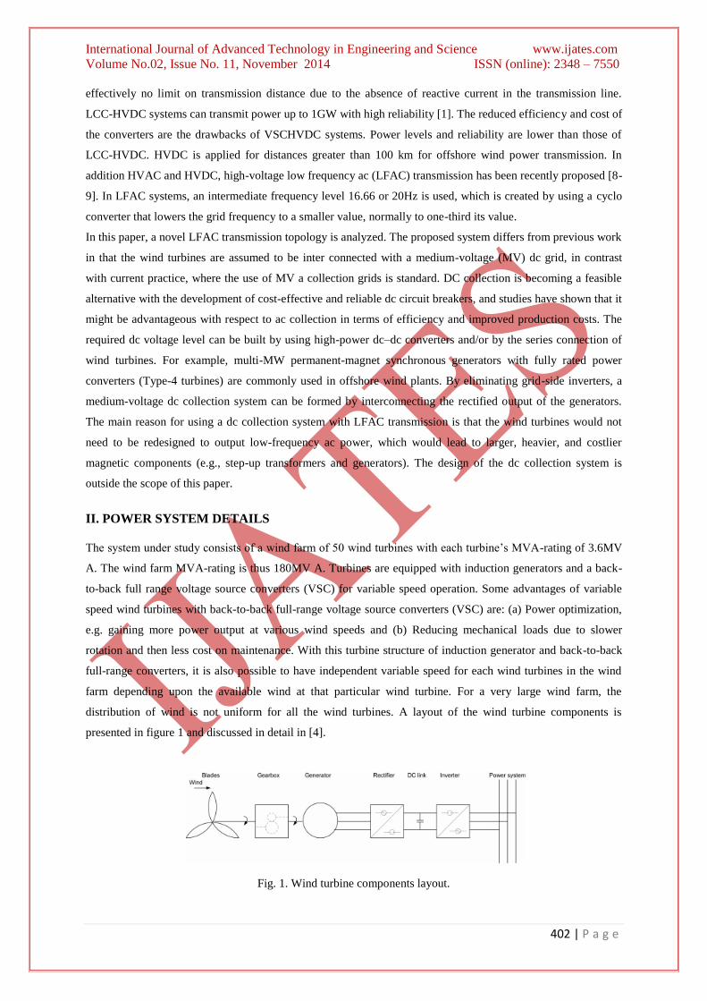
distribution of wind is not uniform for all the wind turbines. A layout of the wind turbine components is
presented in figure 1 and discussed in detail in [4].
Fig. 1. Wind turbine components layout.
International Journal of Advanced Technology in Engineering and Science www.ijates.com
Volume No.02, Issue No. 11, November 2014 ISSN (online): 2348 – 7550
403 | P a g e
A conventional wind farm layout is considered, where all turbines are connected to an AC collector network at
33kV. At the offshore platform, the collector network voltage is stepped up to 100kV with a park transformer.
The collection network cables are modeled using a lumped equivalent Π model. The transmission of power from
the wind farm to the on-land AC grid/pcc is done via a HVDC link, so that a rectifier VSC is present at offshore
platform and an inverter VSC present on-land connects the wind farm to the on-land transmission system. The
multilevel voltage source converters at each end are controlled in a way so all the power from the wind farm is
transmitted to the grid under normal operating conditions.
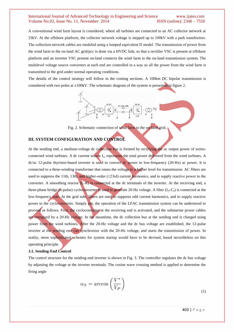
The details of the control strategy will follow in the coming sections. A 100km DC bipolar transmission is
considered with two poles at ±100kV. The schematic diagram of the system is presented in figure 2.
Fig. 2. Schematic connection of wind farm to the on-land grid.
III. SYSTEM CONFIGURATION AND CONTROL
At the sending end, a medium-voltage dc collection bus is formed by rectifying the ac output power of series-
connected wind turbines. A dc current source Iw represents the total power delivered from the wind turbines. A
dc/ac 12-pulse thyristor-based inverter is used to convert dc power to low-frequency (20-Hz) ac power. It is
connected to a three-winding transformer that raises the voltage to a higher level for transmission. AC filters are
used to suppress the 11th, 13th, and higher-order (≥23rd) current harmonics, and to supply reactive power to the
converter. A smoothing reactor (L-R) is connected at the dc terminals of the inverter. At the receiving end, a
three-phase bridge (6-pulse) cycloconverter is used to generate 20-Hz voltage. A filter (Lf-Cf) is connected at the
low-frequency side. At the grid side, filters are used to suppress odd current harmonics, and to supply reactive
power to the cycloconverter. Simply put, the operation of the LFAC transmission system can be understood to
proceed as follows. First, the cycloconverter at the receiving end is activated, and the submarine power cables
are energized by a 20-Hz voltage. In the meantime, the dc collection bus at the sending end is charged using
power from the wind turbines. After the 20-Hz voltage and the dc bus voltage are established, the 12-pulse
inverter at the sending end can synchronize with the 20-Hz voltage, and starts the transmission of power. In
reality, more sophisticated schemes for system startup would have to be devised, based nevertheless on this
operating principle.
3.1. Sending-End Control
The control structure for the sending-end inverter is shown in Fig. 3. The controller regulates the dc bus voltage
by adjusting the voltage at the inverter terminals. The cosine wave crossing method is applied to determine the
firing angle
(1)

International Journal of Advanced Technology in Engineering and Science www.ijates.com
Volume No.02, Issue No. 11, November 2014 ISSN (online): 2348 – 7550
404 | P a g e
Where Vp is the peak value of the cosine wave Note that V*<0 and 90
0< < 180
0(using common notation), since
the converter is in the inverter mode of operation. V and Vs (line-to-neutral, rms) are related by
(2)
A phase-locked loop (PLL) provides the angular position of the ac-side voltage, which is necessary for
generating the firing pulses of the thyristors. It also outputs the rms value of the
Fig. 3. Sending-end inverter control
Fundamental component of the voltage, which is used in the firing-angle calculation.
3.2. Receiving-End Control
The structure of the cycloconverter controller at the receiving end is illustrated in Fig.4. The control objective is
to provide a constant 20-Hz voltage 1 of a given rms value V*cyc (line-to-neutral). The fundamental component
of the cycloconverter voltage Vcyc is obtained with the signal conditioning logic depicted in Fig. 5. The firing
angles are determined with the cosine wave crossing method, as shown in Fig. 6, which uses phase-a as an
example. The firing angles of the phase-a positive and negative converters (denoted as “aP” and “aN” in Fig.3)
are and , respectively. For the positive converter, the average voltage at the 20-Hz terminals is given by
(3)
Where VG the rms is value of the line-to-neutral voltage at the grid side, and nR is the turn’s ratio of the
transformers. The condition = ensures that average voltages with the same polarity are generated
from the positive and negative converter at the 20-Hz terminals. The firing pulses and are not
simultaneously applied to both converters, in order to obtain a non circulating current mode of operation. This
functionality is embedded in the “Bank Selector” block of Fig. 4, which operates based on the filtered
current . Note (for later use) that the maximum line-to-neutral rms value of the 20-Hz cycloconverter
voltage.

International Journal of Advanced Technology in Engineering and Science www.ijates.com
Volume No.02, Issue No. 11, November 2014 ISSN (online): 2348 – 7550
405 | P a g e
(4)
Fig. 4. Receiving-end cycloconverter control. (The reference frame transformation matrix is defined in, and
transforms variables from the stationary to the synchronous reference frame.)
And that a voltage ratio is defined as
(5)
In practice, the theoretical maximum value 1 cannot be achieved, due to the leakage inductance of the
transformers, which was ignored in the analysis.
IV. SYSTEM DESIGN
4.1. Main Power Components
The main power components are selected based on a steady state analysis of the LFAC transmission system
shown in Figure3, under the following assumptions:
• Only fundamental components of voltages and currents are considered. The receiving end is modeled as a 20-
Hz voltage source of nominal magnitude.
• The power losses of the reactor, thyristors, filters, and transformers are ignored.
• The resistances and leakage inductances of transformers are neglected.
•Then filters are represented by an equivalent capacitance corresponding to the fundamental frequency.
• The design is based on rated operating conditions (i.e., maximum power output).
At the steady state, the average value of the dc current Idc is equal to Iw, so the power delivered from the wind
turbines is
(6)

International Journal of Advanced Technology in Engineering and Science www.ijates.com
Volume No.02, Issue No. 11, November 2014 ISSN (online): 2348 – 7550
406 | P a g e
For the 12-pulse converter, the rms value of the current at the transmission side is
(7)
Fig. 5. Details of the signal conditioning block. (LPF first-order low-pass filters, with time constants equal to
0.05 s and 0.01 s for the voltage and current, respectively.)
Fig. 6. Modulator for phase a.
Hence, (7) can be written a
(8)
With
(9)
Let = Vs∟00
and denote the phasors of the line-to neutral voltage and line current, respectively. Since - lags
by [28], it follows that . The active power delivered by the 12-pulse inverter is given
by

International Journal of Advanced Technology in Engineering and Science www.ijates.com
Volume No.02, Issue No. 11, November 2014 ISSN (online): 2348 – 7550
407 | P a g e
(10)
Substitution of (8) into (10) yields
(11)
And
(12)
Fig. 7. Equivalent circuit of the LFAC transmission system at fundamental
Frequency.
The reactive power generated from the 12-pulse inverter is
(13)
From (10)–(13), it follows that:
(14)
The negative sign in (13) and (14) indicates that the 12-pulse inverter always absorbs reactive power. Equation
(14) shows that Qs can be expressed as a function Qs=f (Ps,Vs). Based on the aforementioned analysis, the
steady-state single-phase equivalent circuit of the LFAC transmission system is shown in Fig. 6 The equivalent
capacitance of the sending-end a filters at the fundamental frequency is Ceq .The transmission line is modeled by
an II-equivalent (positive-sequence) circuit using lumped parameters. The well-known hyperbolic trigonometric
expressions for Z’ and Y’/2 are used. Given a power rating of a wind power plant Prated, the maximum reactive
power that is absorbed by the 12-pulse inverter can be estimated according to (14), which yields
(15)
Where Vo is the nominal transmission voltage level (line-to-line rms). Here, it is assumed that the sending-end a
filters supply the rated reactive power to the inverter. Therefore

International Journal of Advanced Technology in Engineering and Science www.ijates.com
Volume No.02, Issue No. 11, November 2014 ISSN (online): 2348 – 7550
408 | P a g e
(16)
Where we =2 rad/s. In addition, the apparent power rating of the transformer at the sending end should
satisfy
(17)
At the 60-Hz grid side, the reactive power capacity of the a filters and the apparent power rating of the
transformers depend on the cycloconverter’s voltage ratio r, which is a design parameter, and the 20-Hz side
power factor , which can be estimated as follows. For a given transmission cable, the voltage ratings (nominal
and maximum voltage), the current rating, and the distributed cable parameters (resistance, inductance, and
capacitance per unit length) are known. Here, it is assumed that a power cable is chosen to transmit the rated
wind power plant power Prated without violating the cable’s voltage and current ratings. (The relationship
between active power through the cable and maximum transmission distance, given a certain cable, will be
discussed later.) For simplicity, it is further assumed that the rms value of line-to-line voltage at both sending
and receiving ends is Vo and the current through Z’ and Lf is approximately equal to the current rating of the
cable Irated. Since the a filters are designed to supply all reactive power to the 12-pulse inverter at the sending
end, the reactive power injected into the 20-Hz side of the cycloconverter can be estimated by using
(18)
Where the first two terms represent the reactive power generated from the cable and the capacitor of the LC
filter, and the last two terms represent the reactive power consumed by the cable and the LC filter’s inductor.
The active power injected into the cycloconverter from the 20-Hz side can be estimated by using
(19)
Where the last two terms represent the power loss of the cable. The 20-Hz side power factor can be estimated
according to (18) and (19). The 60-Hz side power factor PF60
at the transformers’ grid side terminals can be
obtained using the 20-Hz power factor and the voltage ratio r based on the analysis and calculations. Then, the
apparent power rating of each of the three receiving-end transformers StR should satisfy
(20)
Also, it is assumed that the grid-side a filters is designed to supply the rated amount of reactive power to the
cycloconverter.
V. SIMULATION RESULTS
To demonstrate the validity of the proposed LFAC system, simulations have been carried out using
Matlab/Simulink and the Piecewise Linear Electrical Circuit Simulation (PLECS) toolbox. The wind power
plant is rated at 180 MW, and the transmission distance is 160 km.

International Journal of Advanced Technology in Engineering and Science www.ijates.com
Volume No.02, Issue No. 11, November 2014 ISSN (online): 2348 – 7550
409 | P a g e
Fig. 8. MATLAB/Simulink model of LFAC transmission system
Figure8 shows the MATLAB/Simulink model of LFAC transmission system.
Fig. 9. Simulated voltage and current waveforms sending end
Figure9 shows the simulated voltage and current waveforms sending end
Fig. 10. Simulated voltage and current waveforms receiving end
Figure10 shows the simulated voltage and current waveforms receiving end
International Journal of Advanced Technology in Engineering and Science www.ijates.com
Volume No.02, Issue No. 11, November 2014 ISSN (online): 2348 – 7550
410 | P a g e
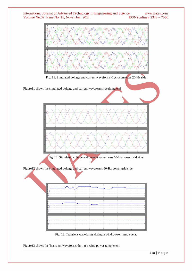
Fig. 11. Simulated voltage and current waveforms Cycloconverter 20-Hz side
Figure11 shows the simulated voltage and current waveforms receiving end
Fig. 12. Simulated voltage and current waveforms 60-Hz power grid side.
Figure12 shows the simulated voltage and current waveforms 60-Hz power grid side.
Fig. 13. Transient waveforms during a wind power ramp event.
Figure13 shows the Transient waveforms during a wind power ramp event.

International Journal of Advanced Technology in Engineering and Science www.ijates.com
Volume No.02, Issue No. 11, November 2014 ISSN (online): 2348 – 7550
411 | P a g e
VI.CONCLUSION
A low-frequency ac transmission system for offshore wind power has been proposed. A method to design the
system’s components and control strategies has been discussed. The use of a low frequency can improve the
transmission capability of submarine power cables due to lower cable charging current. The proposed LFAC
system appears to be a feasible solution for the integration of offshore wind power plants over long distances,
and it might be a suitable alternative over HVDC systems in certain cases. Furthermore, it might be easier to
establish an interconnected low-frequency ac network to transmit bulk power from multiple plants. The major
advantage of such a control scheme of the wind farm side VSC is that the turbines with different generator-
converter topologies (e.g. induction generators with full range converters and double fed induction generators
with partial converters) can be connected to the same VSC platform. The simulation results above show the
system response and the power balance during and outside the grid fault conditions.
REFERENCES
[1] National Grid Electricity Transmission, London, U.K., 2011 offshore development information statement,
Tech. Rep., Sep. 2011.
[2] T.Mai,R.Wiser,D.Sandor,G.Brinkman,G.Heath,P.Denholm,D. J. Hostick, N. Darghouth, A. Schlosser, and
K. Strzepek, “Exploration of high-penetration renewable electricity futures study,” National Renewable
Energy Laboratory, Golden, CO, Tech. Rep. NREL/TP-6A20-52409-1, National Renewable Energy
Laboratory.
[3] N.B.Negra, J.Todorovic, andT. Ackermann, “Loss evaluation of HVAC and HVDC transmission solutions
for large offshore wind farms,” Elect. Power Syst. Res., vol. 76, no. 11, pp. 916–927, Jul. 2006.
[4] S. Bozhko, G. Asher, R. Li, J. Clare, and L. Yao, “Large offshore DFIG based wind farm with line-
commutated HVDC connection to the main grid: Engineering studies, ”IEEE Trans. Energy Convers., vol.
23, no. 1, pp. 119–127, Mar. 2008.
[5] O. Gomis-Bellmunt, J. Liang, J. Ekanayake, R. King, and N. Jenkins, “Topologies of multi terminal HVDC-
VSC transmission for large offshore wind farms, ”Elect. Power Syst. Res., vol. 81, no. 2, pp. 271–281, Feb.
2011.
[6] P. Bresesti, W. L. Kling, R. L. Hendriks, and R. Vailati, “HVDC connection of offshore wind farms to the
transmission system, ”IEEE Trans. Energy Convers., vol. 22, no. 1, pp. 37–43, Mar. 2007.
[7] S.V.Bozhko, R.Blasco-Giménez, R.Li, J.C.Clare, andG.M.Asher, “Control of offshore DFIG-based wind
farm grid with line-commutated HVDC connection,”IEEE Trans. Energy Convers., vol. 22, no. 1, pp. 71–
78, Mar. 2007.
[8] J. Arrillaga, High Voltage Direct Current Transmission, 2nd
ed. London, U.K.: Institution of Electrical
Engineers, 1998.
[9] N. Flourentzou, V. G. Agelidis, and G. D. Demetriades, “VSC-based HVDC power transmission systems:
An overview, ”IEEE Trans. Power Electron., vol. 24, no. 3, pp. 592–602, Mar. 2009.
[10] T. Funaki and K. Matsuura, “Feasibility of the lower frequency AC transmission,” in Proc. IEEE Power
Eng. Soc. Winter Meeting, 2000, vol. 4, pp. 2693–2698.
[11] X. Wang, C. Cao, and Z. Zhou, “Experiment on fractional frequency transmission system,” IEEE Trans.
Power Syst., vol. 21, no. 1, pp. 372–377, Feb. 2006.