Embed Size (px)
Citation preview
POWER TRANSFORMERS
TOSHIBATOSHIBATOSHIBATOSHIBA

1909 44kV, 4.5MVA Bank Hodogaya Substation, Yokohama Electric Co., Japan 1917 110kV, 13.2MVA Bank Inawashiro Hydroelectric Power Co., Japan 1926 154kV, 20MVA Bank Gifu Substation, Nihon Electric Power Co., Japan 1939 220kV, 80MVA Xu Chuna Jiang Power Station, Chang Jin Jiang Hydroelectric Power
Co.,China 1952 275kV, 117MVA Shin-Aimoto Substation, Kansai Electric Power Co., Japan 1958 275kV, 200MVA Chiba Thermal Power Station, Tokyo Electric Power Co., Japan 1960 275kV, 300MVA Yokosuka Thermal Power Station, Tokyo Electric Power Co., Japan 1961 330kV, 300MVA Bank Electricity Commission of New South Wales Substation, Australia 1963 275kV, 430MVA Owase-Mita Thermal Power Station, Chubu Electric Power Co., Japan 1967 275kV, 680MVA Anegasaki Thermal Power Station, Tokyo Electric Power Co., Japan 1967 512.5kV, 600MVA Bank B.C. Hydro & Power Authority Power Station, Canada 1968 525kV, 1200MVA Bank Bonneville Power Administration Substation, U.S.A. 1971 500kV, 1000MVA Bank Shin-Koga Substation, Tokyo Electric Power Co., Japan 1973 275kV, 1100MVA Kashima Thermal Power Station, Tokyo Electric Power Co., Japan 1974 275kV, 450MVA Sunen Substation, Chubu Electric Power Co., Japan 1974 525kV, 1100MVA Sodegaura Power Station, Tokyo Electric Power Co., Japan 1977 500kV, 1500MVA Bank Shin-Koga Substation, Tokyo Electric Power Co., Japan 1977 500kV, 680MVA Okuyoshino Pumped Storage Power Station, Kansai Electric Power Co.,1977 525kV, 1200MVA Fukushima 1st Nuclear Power Station, Tokyo Electric Power Co., Japan1982 765kV, 805.5MVA Bank EDELCA Guri Power Station, Venezuela 1985 515kV, 1260MVA Tsuruga 2nd Nuclear Power Station, Japan Atomic Power Co., Japan 1988 765kV, 1650MVA Bank Furnas Foz do Iguacu Substation, Brazil
TOSHIBA POWER TRANSFORMERS In 1894 Toshiba started producing transformers. Since then, we have successively completed the following
power transformers, each epoch-making when considering Japan's industrial level in those years.

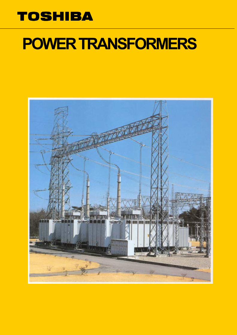
Recently, with the sharp increase in demands for electric power, power transformers have grown in scale while unit capacity has shown as increasing tendency. Especially, thermal/nuclear power plant transformers have displayed a notable tendency toward large capacity. Toshiba has successively renewed its records on unit capacity such as 200MVA in 1958, 300MVA in 1960, 430MVA in 1963, 680MVA in 1967, 1100MVA in 1973, 1200MVA in 1977. In 1985 we manufactured a world-record product of 60Hz, 515kV, 1260MVA delivered to Tsuruga 2nd Nuclear Power Station, Japan Atomic Power Co., Japan. While substation transformers are mostly equipped with on-load tap changers, based on technical know-how under license of Maschinenfabrik Reinhausen GmbH, Germany, Toshiba developed a resistance-type on-load tap changer, which was promptly standardized to ensure high reliability. A large number of transformers providing on-load tap changers up to 800 VIVA are being produced, and many auto-trans-formers up to 765 kV-1650 MVA bank are being manufactured by
Toshiba. Recently, transformers connected to gas-insulated switchgear (GIS) are being broadened in application. As to all voltage classes no larger than 500kV, Toshiba established a G IS connection technique, resulting in the successful manufacture and delivery of 500kV, GIS direct-coupled transformers. Transformers for pumped-storage power stations and underground substations are subject to strict restrictions on transport dimensions and weight. Through adopting an innovative method of dividing components to facilitate transportation and assembly technique, Toshiba manufactured and delivered three-section type 275kV, 300MVA transformers to underground substations, 345kV, 300MVA transformer to pumped-storage power station and a nine-section type 500kV, 680MVA transformer to an underground power station, whose equivalent cannot be seen in any part of the world. By initiating research on 500kV transformers early in 1955, and through exerting efforts subsequently several times in related research and development activities,
ictPtJt5ttb11ItBaSTagsprwRawecu
n 1967 Toshiba successfully ompleted and delivered a 500kV ransformer to the B.C. Hydro & ower Authority, Canada. This was
he first practical model ever built in apan for an ultra high-voltage power ransformer. Further, in 1971, 00/275kV-1000MVA auto-ransformer-banks were completed as he first 500kV transformer product to e delivered for domestic use. In 977, Toshiba also delivered 500MVA-bank autotransformers.
n 1988, 765/525kV1650MVA auto-ransformer-banks were delivered to razil as the first 765kV utotransformer product. upported by such technology, oshiba successively manufactured nd delivered the aforementioned igantic thermal, nuclear power tation transformers and hydroelectric ower station transformers which equires the difficult transportation ith strict transport restrictions. egarding transformers of the 500kV nd above, Toshiba boasts one of the orld's largest supply record, having xceeded 120,OOOMVA in total apacity of supplied transformers (330nits).
Features
High Reliability
Core Structure Offers Splendid Characteristics
Advanced Winding Application
Perfect Drying Process
Sufficient Mechanical Strength against Short-circuiting
Highly Efficient Cooling
Perfect Measure against Leakage Flux
Adequate Oil-leakage Preventive Structure
Simplified Installation Work
4

tcei
The high reliability of Toshiba products is widely recognized by users in Japan and abroad. It is backed up by an accumulation of technology, which has been carefully achieved by adding new technologies
ul
Adopting of a miter-joint core, in which the characteristics of grain-oriented silicon steel are fully
Tw
Toshiba adopts the disk windings with optimum insulation design based on the voltage oscillation analysis by computer in high voltage winding.
Tf
Toshiba transformers are of the core type, in which the core-and-coil assembly is independent of the tank, so that the core-and-coil assembly can be completely dried through our unique vapor phase drying method.
htpic
Efforts are now being exerted to ensure sufficient short-circuit strength by maintaining a balance of ampere-turns between windings, determining materials to be used on the basis of mechanical force calculated by computers, and exercising adequate care in the pretreatment fastened by applying pressure with a
wrtt
Solup
In a large-capacity, high-impedance transformer, probable leakage flux is calculated by computers on each part so that a magnetic shield, corresponding to the result of each calculation, is provided on the inner surface of the tank and the clamp surface opposite of the coil, to prevent a large amount of leakage flux.
um
The tank is of all-welded construction in which there is no possibility of oil leakage. Nitrile rubber gaskets, excellent in oil resistance and weather resistance, are
apa
o conventional technologies, the ability to design apable transformers, an excellent working nvironments and facilities, and thorough use of
nspection and testing system.
tilized, displays with Toshiba transformers less no-load oss and no-load current, as well as low noise.
he windings are manufactured by highly skilled orkers in a dust-proofed room.
oshiba transformers offer excellent insulation, and are ree from shrinkage caused by aging.
ydraulic jack on a thick annular insulating plate set on he top thereof. Further more, a perfectly dried, recompressed, pressboard is used, so that the winding
s provided with adequate strength to withstand short-ircuit mechanical force.
inding conductors are uniformly insulated, and no einforcement of insulation is necessary. Because of his favorable voltage distribution, the rise of emperature is uniform.
Forced-cooling is used on the winding and inside the core, with oil kept circulating through its interior in order to achieve a large cooling effect. Since the windings are effective in voltage distribution, the
lits are provided on core-leg clamping plates and so n, in order to reduce stray loss as a prevention against
ocal overheating. Further more, nonmagnetic steel is sed as necessary in large-current bushing pockets and arts, in the vicinity of large-current lead.
sed in such openings as manholes and accessory ounting parts.
dvantage of being a built-in type, it is a standard ractice to transport the on-load tap changer as ssembled in the main tank.
Since the transformer is transported with its core-and-coil assembly kept in the factory-assembled stage, high reliability is maintained and installation in the field is simplified. Further more, by utilizing its
5
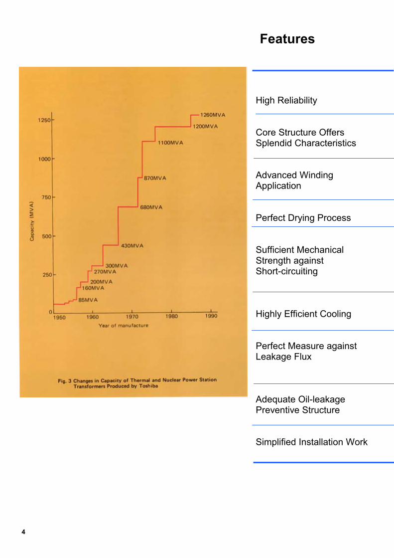
Core Three-phase transformers usually employ three-leg core. Where transformers to be transported by rail are large capacity, five-leg core is used to curtail them to within the height limitation for transport. Even among thermal/nuclear power station transformers, which are usually transported by ship and freed from restrictions on in-land transport, gigantic transformers of the 1000MVA class employ five-leg core to prevent leakage flux, minimize vibration, increase tank strength, and effectively use space inside the tank. Regarding single-phase transformers, two-leg core is well known. Practically, however, three-leg core is used; four-leg core and five-leg core are used in large-capacity transformers. The sectional areas of the yoke and side leg are 50% of that of the main leg; thus, the core height can be reduced to a large extent compared with the two-leg core. For core material, high-grade, grain-oriented silicon steel strip is used.
cfobcscwdathsI wleumpocoppppcWaintos
The steel strip surface is subjected to inorganic insulation treatment. All cores employ miter-joint core construction. Yokes are jointed at an angle of 45 ー to utilize the magnetic flux directional characteristic of steel strip. A computer-controlled automatic machine cuts grain-oriented silicon steel strip with high accuracy and free of burrs, so that magnetic characteristics of the grain-oriented silicon steel remains unimpaired. (Fig. 6) Silicon steel strips are stacked in a circle-section. Each core leg is fitted with tie plates on its front and rear side, with resin-impregnated glass tape wound around the outer circumference. Sturdy clamps applied to front and rear side of the upper and lower yokes are bound together with glass tape. And then, the resin undergoes heating for hardening to tighten the band so that the core is evenly clamped (Fig. 7). Also, upper and lower clamps are
6
onnected by a core leg tie plate; re and hind clamps by connecting
ars. As a result, the core is so onstructed that the actual silicon trip is held in a sturdy frame onsisting of clamps and tie plates, hich resists both mechanical force uring hoisting the core-and-coil ssembly and short circuits, keeping e silicon steel strip protected from
uch force. n large-capacity transformers, hich are likely to invite increased akage flux, nonmagnetic steel is sed or slits are provided in steel embers to reduce the width for
reventing stray loss from increasing n metal parts used to clamp the ore and for preventing local verheat. The core interior is rovided with many cooling oil ducts arallel to the lamination to which a art of the oil flow forced by an oil ump is introduced to achieve forced ooling. hen erecting a core after
ssembling, a special device shown Fig. 8 is used so that no strain due bending or slip is produced on the
ilicon steel plate.
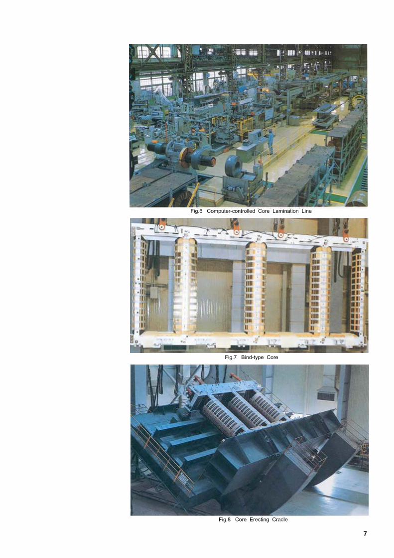
Fig.6 Computer-controlled Core Lamination Line
Fig.7 Bind-type Core
Fig.8 Core Erecting Cradle
7
Winding
C
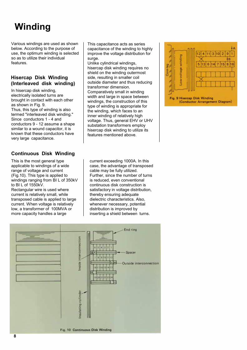
This capacitance acts as series capacitance of the winding to highly improve the voltage distribution for surge. Unlike cylindrical windings,
Vbusf
H(IebaTtScskv
Tar(wtRctclm
arious windings are used as shown elow. According to the purpose of se, the optimum winding is selected o as to utilize their individual eatures.
ontinuous Disk Winding
hisercap disk winding requires no shield on the winding outermost side, resulting in smaller coil outside diameter and thus reducing transformer dimension. Comparatively small in winding width and large in space between windings, the construction of this type of winding is appropriate for the winding, which faces to an inner winding of relatively high voltage. Thus, general EHV or UHV substation transformers employ hisercap disk winding to utilize its features mentioned above.
isercap Disk Winding Interleaved disk winding)n hisercap disk winding, lectrically isolated turns are rought in contact with each other s shown in Fig. 9. hus, this type of winding is also
ermed "interleaved disk winding." ince conductors 1 - 4 and onductors 9 - 12 assume a shape imilar to a wound capacitor, it is nown that these conductors have ery large capacitance.
his is the most general type pplicable to windings of a wide ange of voltage and current Fig.10). This type is applied to indings ranging from BI L of 350kV
o BI L of 1550kV. ectangular wire is used where urrent is relatively small, while ransposed cable is applied to large urrent. When voltage is relatively
ow, a transformer of 100MVA or ore capacity handles a large
8
current exceeding 1000A. In this case, the advantage of transposed cable may be fully utilized. Further, since the number of turns is reduced, even conventional continuous disk construction is satisfactory in voltage distribution, thereby ensuring adequate dielectric characteristics. Also, whenever necessary, potential distribution is improved by inserting a shield between turns.
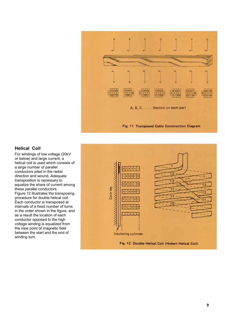
Helical Coil
For windings of low voltage (20kV or below) and large current, a helical coil is used which consists of a large number of parallel conductors piled in the radial direction and wound. Adequate transposition is necessary to equalize the share of current among these parallel conductors. Figure 12 illustrates the transposing procedure for double helical coil. Each conductor is transposed at intervals of a fixed number of turns in the order shown in the figure, and as a result the location of each conductor opposed to the high voltage winding is equalized from the view point of magnetic field between the start and the end of winding turn.9
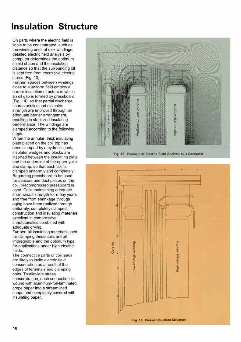
Insulation Structure On parts where the electric field is liable to be concentrated, such as the winding ends of disk windings, detailed electric field analysis by computer determines the optimum shield shape and the insulation distance so that the surrounding oil is kept free from excessive electric stress (Fig. 13). Further, spaces between windings close to a uniform field employ a barrier insulation structure in which an oil gap is formed by pressboard (Fig. 14), so that partial discharge characteristics and dielectric strength are improved through an adequate barrier arrangement, resulting in stabilized insulating performance. The windings are clamped according to the following steps. When the annular, thick insulating plate placed on the coil top has been clamped by a hydraulic jack, insulator wedges and blocks are inserted between the insulating plate and the underside of the upper yoke and clamp, so that each coil is clamped uniformly and completely. Regarding pressboard to be used for spacers and duct pieces on the coil, precompressed pressboard is used. Coils maintaining adequate short-circuit strength for many years and free from shrinkage through aging have been realized through uniformly, completely clamped construction and insulating materials excellent in compressive characteristics combined with adequate drying. Further, all insulating materials used for clamping these coils are oil impregnable and the optimum type for applications under high electric fields. The connective parts of coil leads are likely to invite electric field concentration as a result of the edges of terminals and clamping bolts. To alleviate stress concerntration, each connection is wound with aluminum-foil-laminated crepe paper into a streamlined shape and completely covered with insulating paper.
10

PaIwlttievbpp●●●
●●
●Tfptdf
DI cinadapwthpcSeb
revention of Internal Partial Discharge nd Insulation Treatment
n the case of transformers specified ith several reduced-insulation
evels, such as EHV or UHV ransformers, the ratio between esting voltage and operating voltage s small. To ensure high reliability in xtended operation under high oltage, thorough quality control must e effected to prevent dangerous artial discharge. Main causes of artial discharge include: Incompletely dried insulations Voids in insulations Electrically floating metals and incomplete contact under electric field of high intensity
Edged electrodes Concentrated electric stress applied to oil gap
Intermixed foreign matter or dust o eliminate these causes, the
ollowing measures are taken in the rocess of design and manufacture;
o confirm reliability, a partial ischarge test is conducted at the inal stage.
rying/Oil Filling Treatment n the core-type transformer, the ore-and-coil assembly is dependent of the tank, so that the ssembly is allowed to completely ry. When drying the core-and-coil ssembly, Toshiba's innovative vapor hase drying method is used, in hich special oil vapor is sprayed on e assembly to utilize latent heat roduced when the oil vapor ondenses. ince heating is effected deep inside venly and quickly, the assembly can e completely dried
winUcladhuofWbeevreinimdevaUtr(wanininadanab
RVacougthinua
EInvoanlaimUinocshmoiToncoedbocofaAcoan
by computer to determine the optimum electrode shape, insulation construction, and insulation dimensions to ensure careful control of the electric field.
D
Fig. 15 Wave Form of Partial Discharge
ithout causing damage to the sulations. pon completion of drying, the coil is amped in a low-humidity room justed to 5% or below relative midity to prevent any reabsorption humidity (Fig. 17). hen a core-and-coil assembly has en installed in a tank, the tank is acuated to a high vacuum state to move reabsorbed humidity on the sulations surface and voids in pregnated insulation; then aerated oil is filled under the high cuum.
pon completion of a factory test, the ansformer is transported to the site ith its accessories disassembled d packed as required) for
stallation and assembly. During stallation and assembly at site, equate care is taken to dehydration d the prevention of water sorption as in the case of factory
emoving Voids oids in impregnated insulation such s paper and pressboard can be mpletely removed by oil filling
nder a vacuum. Depending on the lue material and the using method, ere is a possibility of creating voids side. Thus, oil-impregnable glue is sed and due care is exercised to void using excessive glue.
F
lectric Field Control
sulation between high- and low ltage windings, between windings d the tank/core, and between coilyers depends mainly on the oil pregnated paper and oil gaps.
nless voids are created in layers of sulation paper, partial discharge curs first on oil gaps. The electrode ape and insulation dimensions ust be carefully selected to keep the l free from excessive stress. he electric field tends to concentrate the small shaped lead wires from ils and lead wire connections, ges of terminals and clamping lts, and metal structures such as res, clamps, and the tank which are cing these high-voltage electrodes. s to parts liable to invite electric field ncentration, detailed electric field alysis is conducted
ust Control
The penetration of all sorts of dust and foreign matter, as well as metallic particles, is unfavorable to transformers; such matter incurs partial discharge. To avoid this penetration, the transformer core-and-coil is assembled in a dust-controlled dust-proofed room; winding operations are performed in a double-ceiling room -a dust-proofed room provided with an additional ceiling (Fig. 16). Dust is further controlled by coating metal structures of the core-and-coil assembly and the tank interior with white paint; should dust or foreign matter penetrate from the exterior, it can be readily detected.ig.16 Dust-proofed Workshop
Fig.17 Vapor-phase Drying Oven
F
ig.18 Transformer Final Testing11
1
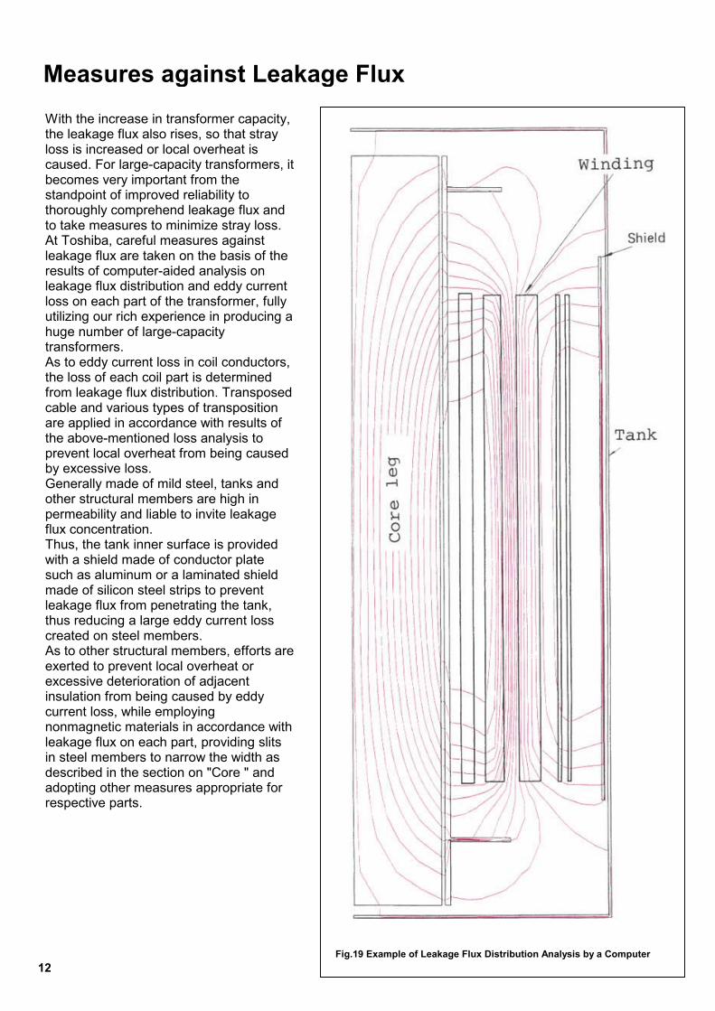
Measures against Leakage Flux
With the increase in transformer capacity, the leakage flux also rises, so that stray loss is increased or local overheat is caused. For large-capacity transformers, itbecomes very important from the standpoint of improved reliability to thoroughly comprehend leakage flux and to take measures to minimize stray loss. At Toshiba, careful measures against leakage flux are taken on the basis of the results of computer-aided analysis on leakage flux distribution and eddy current loss on each part of the transformer, fully utilizing our rich experience in producing a huge number of large-capacity transformers. As to eddy current loss in coil conductors, the loss of each coil part is determined from leakage flux distribution. Transposed cable and various types of transposition are applied in accordance with results of the above-mentioned loss analysis to prevent local overheat from being caused by excessive loss. Generally made of mild steel, tanks and other structural members are high in permeability and liable to invite leakage flux concentration. Thus, the tank inner surface is provided with a shield made of conductor plate such as aluminum or a laminated shield made of silicon steel strips to prevent leakage flux from penetrating the tank, thus reducing a large eddy current loss created on steel members. As to other structural members, efforts areexerted to prevent local overheat or excessive deterioration of adjacent insulation from being caused by eddy current loss, while employing nonmagnetic materials in accordance with leakage flux on each part, providing slits in steel members to narrow the width as described in the section on "Core " and adopting other measures appropriate for respective parts.Fig.19 Example of Leakage Flux Distribution Analysis by a Computer 2

Thfobethwtrafo●
●
●
●
●
●
Tank
e tank is manufactured byrming and welding steel plate to used as a container for holding
e core and coil assembly together ith insulating oil. The Toshiba nsformer tank offers the
llowing features: Subjected to automatic beam welding machine (Fig. 20) and other special facilities, the tank possesses high quality and strength. Transformers to be transported by ship are structured in a semioval shape on both ends of the tank and provided with reinforcement members rationally arranged, resulting in increased strength and decreased weight. The tank bottom is fitted with a skidbase by welding and provided with pull lugs to facilitate rolling in the longitudinal and transverse directions. Capable of withstanding a high vacuum of 0.1 torr or below, the tank can be filled with oil under a vacuum; to thoroughly remove gases and moisture from the insulation. The tank is of completely enclosed,welded construction. Oilproof nitrile rubber gaskets are used on those parts which must be removed from the standpoint of assembly in the field or during maintenance; flanges thereon are provided with accurately machined grooves or gasket retainers to ensure proper tightening of gaskets. Consequently, there is no possibility of oil leakage over an extended period (Fig. 21, 22). The tank internal surface and the metallic part of the core-and-coil assembly are coated with white paint to help observe dust accumulation.
Fig.20 Automatic beam welding machine
13

Cooling System
PtSpwmhv(
S
raefbecomteun
This is a system in which unit coolers, each consisting of a cooling tube, fan, oil-submerged pump, and oil flow indicator assembled as a unit, are arranged around the tank in the necessary amount. Steel pipe fitted with fins and dipped in zinc, with an excellent corrosionproof characteristics, is adopted as
In case that a large amount of cooling air is unavailable such as in underground substations, water cooled type is applied. The oil circulates through the casing outside the water tubes, and the water circulates through the water to be. Where the cooling water pressure
14
anel type radiators are mounted on he tank. ince any cooling fans and oil umps are not used, this type is idely applied owing to its facilitated aintenance, Panel type radiators
ave features of decreasing oil olume and withstanding a vacuum Fig. 23).
elf-cooled Type
diators to increase the cooling fect. Usually, the cooling fans will put into service when natural oling becomes inadequate to aintain the oil and/or winding mperature within the specified limit der a heavy load (Fig. 24).
cooling pipe. In the tank cooled oil is delivered to the windings and ducts on the core, so that each part is cooled uniformly and effectively (Fig. 25). In some cases, a cooling device consisting of a combination of oil-submerged pumps and radiators with cooling fans is used as a cooling device for multirating of a forced-oil, forced-aircooled/forced-aircooled/self-cooled transformer (Fig. 26).
is maintained at a higher level than oil pressure, a double-tube-type cooler is applied (Fig. 27).
Cooling System Capacity Self-cooling type (ONAN) 30,000kVA or below
Forced-air-cooled type (ONAF) 30,000kVA~150.000k
Forced-oil, forced-air-cooled type (OFAF) 150,000kVA or more
T
Fig.23 Self-cooled type Transformer Fig.24 Forc
Cooling equipment
Panel-type radiators
VA Panel-type radiators and cooling fans
Unit cooler or panel-type radiator, and
Cooling fans are installed on the
Air-cooled-air-cooled T
Forced-oil, Forced-air-cooled Type
Instal
ed-air-coole
Forced-oil, Water-cooled Type
able 1 Standard design of cooling system
lation of cooling fans and pumps
In addition to the above, a forced-oil, water-cooled type (OFWF) and forced-oil, self-cooled type(OFAN) are available.
d type Transformer
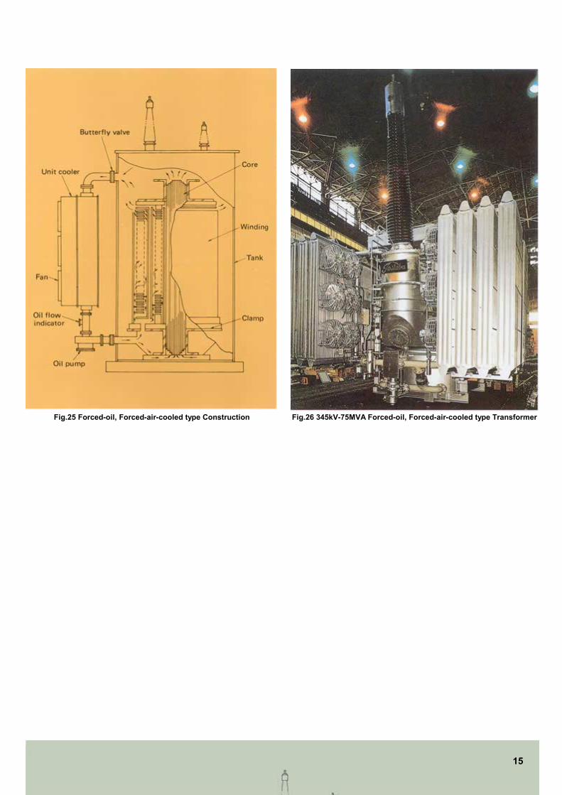
Fig.25 Forced-oil, Forced-air-cooled type Construction Fig.26 345kV-75MVA Forced-oil, Forced-air-cooled type Transformer
Fig.27 Forced-oil, Water-cooled type Construction
15
Accessories Oil Preservation System Oe(p
DSTisscinmcSobaoaDT•
•
•
•
•
•
DFAOabRgisT
il conservator type, nitrogen-nclosed type, and diaphragm type Type OH-D), are employed for the oil reservation system.
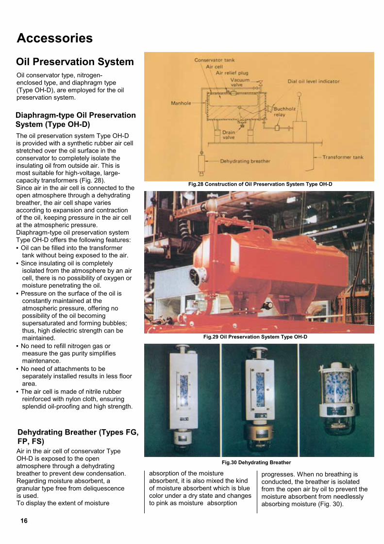
iaphragm-type Oil Preservation ystem (Type OH-D) he oil preservation system Type OH-D provided with a synthetic rubber air cell tretched over the oil surface in the onservator to completely isolate the sulating oil from outside air. This is ost suitable for high-voltage, large-
apacity transformers (Fig. 28). ince air in the air cell is connected to the pen atmosphere through a dehydrating reather, the air cell shape varies ccording to expansion and contraction f the oil, keeping pressure in the air cell t the atmospheric pressure. iaphragm-type oil preservation system ype OH-D offers the following features: Oil can be filled into the transformer tank without being exposed to the air.
Since insulating oil is completely isolated from the atmosphere by an air cell, there is no possibility of oxygen or moisture penetrating the oil.
Pressure on the surface of the oil is constantly maintained at the atmospheric pressure, offering no possibility of the oil becoming supersaturated and forming bubbles; thus, high dielectric strength can be maintained.
No need to refill nitrogen gas or measure the gas purity simplifies maintenance.
No need of attachments to be separately installed results in less floor area.
The air cell is made of nitrile rubber reinforced with nylon cloth, ensuring splendid oil-proofing and high strength.
ehydrating Breather (Types FG, P, FS) ir in the air cell of conservator Type H-D is exposed to the open tmosphere through a dehydrating reather to prevent dew condensation. egarding moisture absorbent, a ranular type free from deliquescence used. o display the extent of moisture
absorption of the moisture absorbent, it is also mixed the kind of moisture absorbent which is blue color under a dry state and changes to pink as moisture absorption
pcfma
Fig.28 Construction of Oil Preservation System Type OH-D
Fig.29 Oil Preservation System Type OH-D
Fig.30 Dehydrating Breather
16
rogresses. When no breathing is onducted, the breather is isolated rom the open air by oil to prevent the
oisture absorbent from needlessly bsorbing moisture (Fig. 30).

DFoiplldrttcsrpsmts
P
B
ial Oil Level Indicator
or indicating on the dial a change f oil in the conservator, thendicator is tilted downward to ermit easy supervision of the oil
evel even if it is installed at a high evel. Any change in the oil level is etected by a float, converted into otary motion by a gear, and ransmitted to the external pointer hrough a magnet. The float side is ompletely isolated from the pointer ide by a partition through which the otary shaft does not pass, reventing oil leakage. The pointer ide is of airtight construction with oisture absorbent contained
herein to prevent the glass inner ide from clouding (Fig. 31).
Fig.31 Construction of Dial Oil Level Indicator
rotective Relays
The following protective devices are used so that, upon a fault development inside a transformer, an alarm is set off or the transformer is disconnected from the circuit. In the event of a fault, oil or insulations decomposes by heat, producing gas or developing an impulse oil flow. To detect these phenomena, a Buchholtz relay is installed.uchholtz Relay
The Buchholtz relay is installed at the middle of the connection pipe between the transformer tank and the conservator. There are a 1st stage contact and a 2nd stage contact as shown in Fig. 32. The 1st stage contact is used to detect minor faults. When gas produced in the tank due to a minor fault surfaces to accumulate in the relay chamber within a certain amount (0.3Q-0.35Q) or above, the float lowers and closes the contact, thereby actuating the alarm device. The 2nd stage contact is used to detect major faults. In the event of amajor fault, abrupt gas production causes pressure in the tank to flow oil into the conservator. In this case, the float is lowered to close the contact, thereby causing the circuit breaker to trip or actuating the alarm device.Fig.32 Buchholtz Relay
17
Temperature Measuring Device
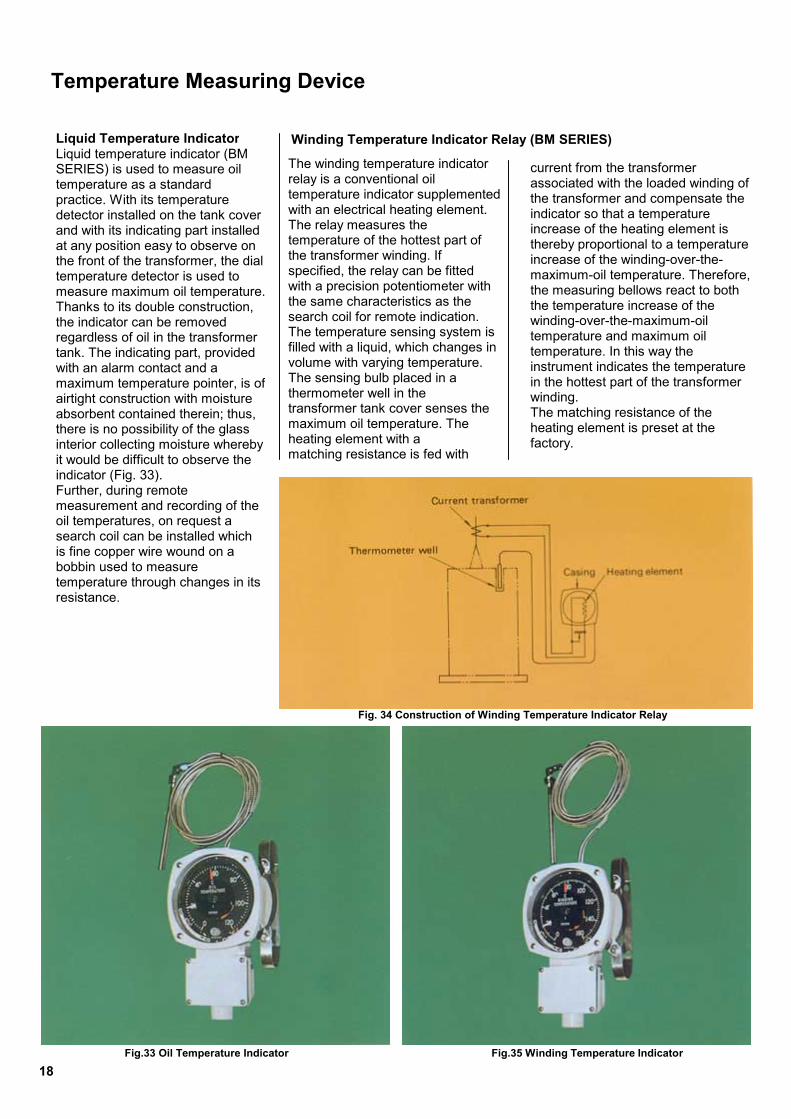
The winding temperature indicator relay is a conventional oil temperature indicator supplemented with an electrical heating element. The relay measures the temperature of the hottest part of the transformer winding. If specified, the relay can be fitted with a precision potentiometer with the same characteristics as the search coil for remote indication. The temperature sensing system is filled with a liquid, which changes in volume with varying temperature. The sensing bulb placed in a thermometer well in the transformer tank cover senses the maximum oil temperature. The heating element with a matching resistance is fed with
current from the transformer associated with the loaded winding of the transformer and compensate the indicator so that a temperature increase of the heating element is thereby proportional to a temperature increase of the winding-over-the-maximum-oil temperature. Therefore, the measuring bellows react to both the temperature increase of the winding-over-the-maximum-oil temperature and maximum oil temperature. In this way the instrument indicates the temperature in the hottest part of the transformer winding. The matching resistance of the heating element is preset at the factory.
18
Liquid Temperature IndicatorLiquid temperature indicator (BM SERIES) is used to measure oil temperature as a standard practice. With its temperature detector installed on the tank cover and with its indicating part installed at any position easy to observe on the front of the transformer, the dial temperature detector is used to measure maximum oil temperature.Thanks to its double construction, the indicator can be removed regardless of oil in the transformer tank. The indicating part, provided with an alarm contact and a maximum temperature pointer, is ofairtight construction with moisture absorbent contained therein; thus, there is no possibility of the glass interior collecting moisture whereby it would be difficult to observe the indicator (Fig. 33). Further, during remote measurement and recording of the oil temperatures, on request a search coil can be installed which is fine copper wire wound on a bobbin used to measure temperature through changes in its resistance.
Fig.33 Oil Temperature Indicator
Winding Temperature Indicator Relay (BM SERIES)
Fig. 34 Construction of Winding Temperature Indicator Relay
Fig.35 Winding Temperature Indicator
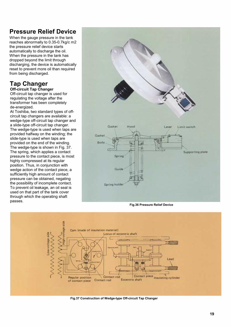
Pressure Relief Device
When the gauge pressure in the tank reaches abnormally to 0.35-0.7kg/c m2 the pressure relief device starts automatically to discharge the oil. When the pressure in the tank has dropped beyond the limit through discharging, the device is automatically reset to prevent more oil than required from being discharged.Tap Changer OOrtdAcwaTpspTTphpwsptTutp
Fig.36 Pressure Relief Device
ff-circuit Tap Changer ff-circuit tap changer is used for
egulating the voltage after the ransformer has been completely e-energized. t Toshiba, two standard types of off-ircuit tap changers are available: a edge-type off-circuit tap changer and slide-type off-circuit tap changer. he wedge-type is used when taps are rovided halfway on the winding; the lide-type is used when taps are rovided on the end of the winding. he wedge-type is shown in Fig. 37. he spring, which applies a contact ressure to the contact piece, is most ighly compressed at its regular osition. Thus, in conjunction with edge action of the contact piece, a ufficiently high amount of contact ressure can be obtained, negating
he possibility of incomplete contact. o prevent oil leakage, an oil seal is sed on that part of the tank cover
hrough which the operating shaft asses.
Fig.37 Construction of Wedge-type Off-circuit Tap Changer
19
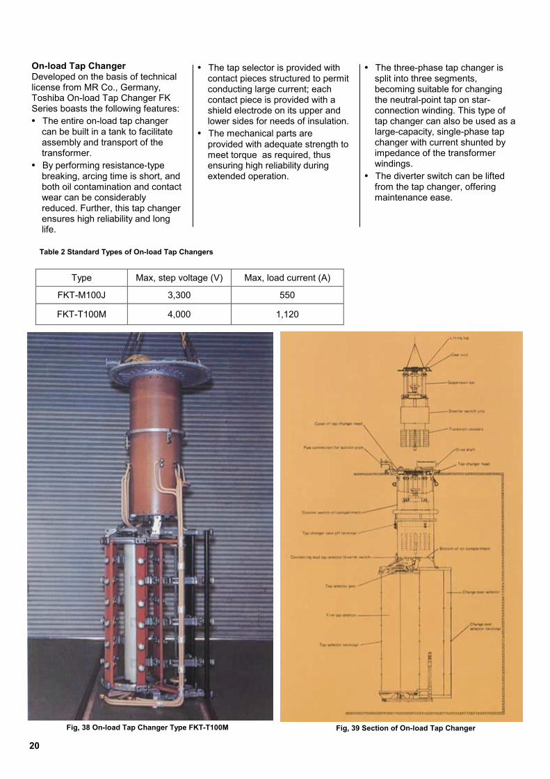
• The tap selector is provided with contact pieces structured to permit conducting large current; each contact piece is provided with a shield electrode on its upper and lower sides for needs of insulation.
• The mechanical parts are provided with adequate strength to meet torque as required, thus ensuring high reliability during extended operation.
• The three-phase tap changer is split into three segments, becoming suitable for changing the neutral-point tap on star-connection winding. This type of tap changer can also be used as a large-capacity, single-phase tap changer with current shunted by impedance of the transformer windings.
• The diverter switch can be lifted from the tap changer, offering maintenance ease.
2
On-load Tap Changer Developed on the basis of technical license from MR Co., Germany, Toshiba On-load Tap Changer FK Series boasts the following features: • The entire on-load tap changer
can be built in a tank to facilitate assembly and transport of the transformer.
• By performing resistance-type breaking, arcing time is short, and both oil contamination and contact wear can be considerably reduced. Further, this tap changer ensures high reliability and long life.
FK
FK
Table 2 Standard Types of On-load Tap Changers
F
0
Type Max, step voltage (V) Max, load current (A)
T-M100J 3,300 550
T-T100M 4,000 1,120
ig, 38 On-load Tap Changer Type FKT-T100M Fig, 39 Section of On-load Tap Changer
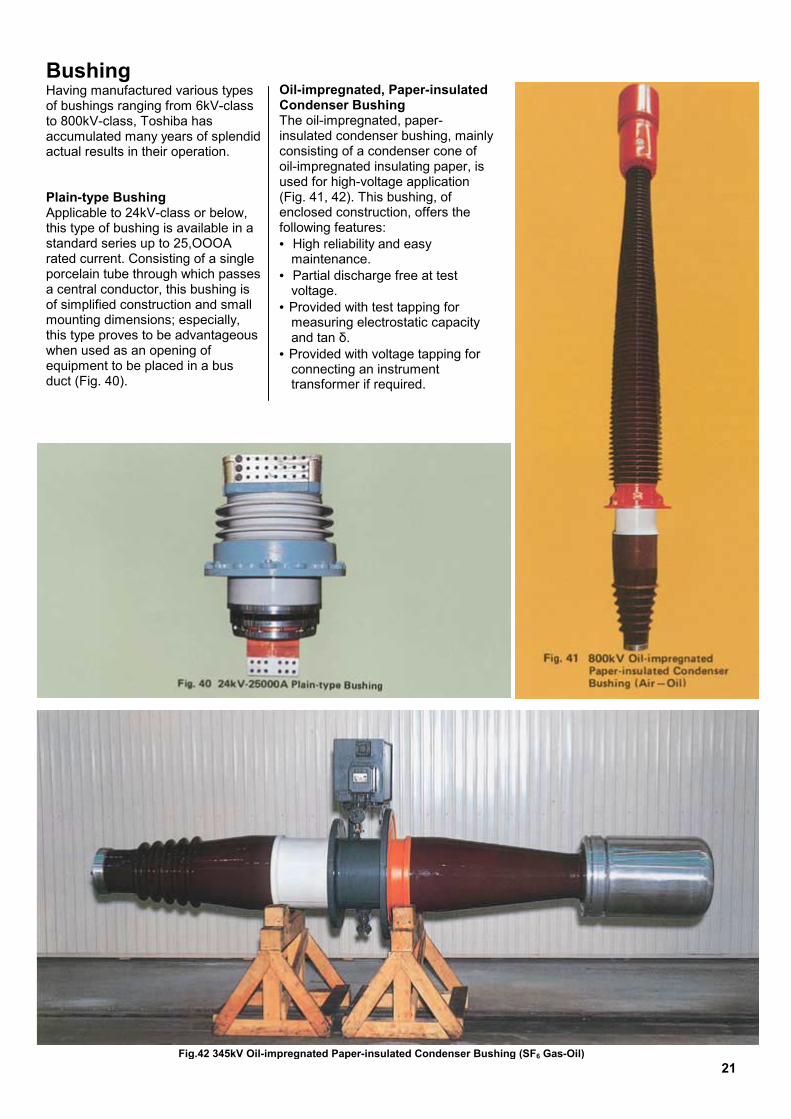
Bushing Having manufactured various types of bushings ranging from 6kV-class to 800kV-class, Toshiba has accumulated many years of splendid actual results in their operation. Plain-type Bushing Applicable to 24kV-class or below, this type of bushing is available in a standard series up to 25,OOOA rated current. Consisting of a single porcelain tube through which passes a central conductor, this bushing is of simplified construction and small mounting dimensions; especially, this type proves to be advantageous when used as an opening of equipment to be placed in a bus duct (Fig. 40).
Oil-impregnated, Paper-insulated Condenser Bushing The oil-impregnated, paper-insulated condenser bushing, mainly consisting of a condenser cone of oil-impregnated insulating paper, is used for high-voltage application (Fig. 41, 42). This bushing, of enclosed construction, offers the following features: • High reliability and easy
maintenance. • Partial discharge free at test
voltage. • Provided with test tapping for
measuring electrostatic capacity and tan δ.
• Provided with voltage tapping for connecting an instrument transformer if required.
Fig.42 345kV Oil-impregnated Paper-insulated Condenser Bushing (SF6 Gas-Oil) 21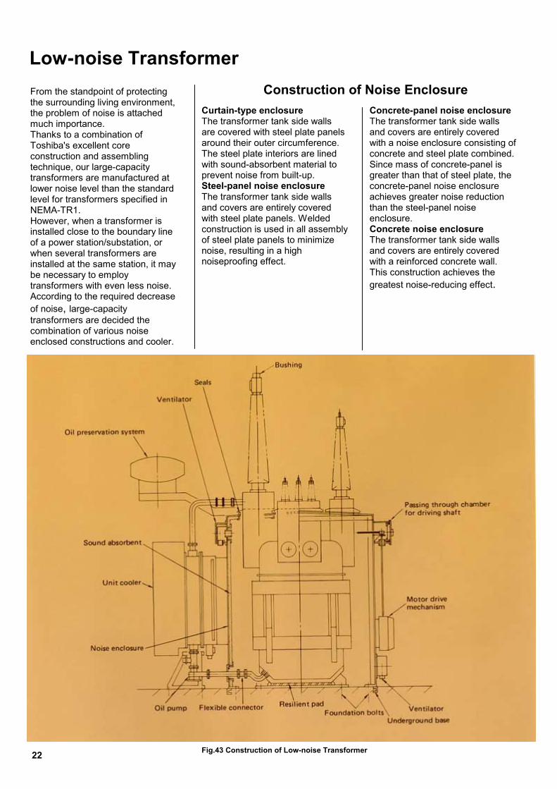
From the standpoint of protecting the surrounding living environment, the problem of noise is attached much importance. Thanks to a combination of Toshiba's excellent core construction and assembling technique, our large-capacity transformers are manufactured at lower noise level than the standard level for transformers specified in NEMA-TR1. However, when a transformer is installed close to the boundary line of a power station/substation, or when several transformers are installed at the same station, it may be necessary to employ transformers with even less noise. According to the required decrease of noise, large-capacity transformers are decided the combination of various noise enclosed constructions and cooler.
Curtain-type enclosureThe transformer tank side walls are covered with steel plate panels around their outer circumference. The steel plate interiors are lined with sound-absorbent material to prevent noise from built-up. Steel-panel noise enclosure The transformer tank side walls and covers are entirely covered with steel plate panels. Welded construction is used in all assembly of steel plate panels to minimize noise, resulting in a high noiseproofing effect.
Concrete-panel noise enclosureThe transformer tank side walls and covers are entirely covered with a noise enclosure consisting of concrete and steel plate combined. Since mass of concrete-panel is greater than that of steel plate, the concrete-panel noise enclosure achieves greater noise reduction than the steel-panel noise enclosure. Concrete noise enclosure The transformer tank side walls and covers are entirely covered with a reinforced concrete wall. This construction achieves the greatest noise-reducing effect.
Low-noise Transformer
Fig.43 Construction of Low-noise Transformer
Construction of Noise Enclosure
22

LTnf● ● ● ●
arge-capacity transformers of the 00-300MVA class adopt the llowing various types of
ombination in accordance with oise level requirements: Noise level: 70-80 dB The transformer tank side walls are covered with a curtain-type enclosure; a low-noise unit cooler with low-speed cooling fan is installed. Noise level: 60-70 dB
● Noise level: 55-65 dB The transformer tank is covered with a concrete-panel noise enclosure; a radiator bank or low-noise unit cooler with noise- absorbing duct is installed. ● Noise level: 50- 60 dB The transformer tank is placed in a concrete noise-enclosure. Generally, an forced-oil, self- cooled system is employed with the radiator bank installed
ow-noise Cooler ypical coolers applicable to low- oise transformers include the ollowings: Low-noise unit cooler with low-
speed cooling fan Low-noise unit cooler with sound-
absorbing duct on the front of cooling fan Independent radiator of self-
cooled type or forced-oil, self-cooled type Water-cooled unit cooler
L1focn● ●
The trans with a ste enclosur cooler wi fan or no installed.Fig.44 Steel-panel Noise Enclosure
Low-noise Combination of Transformer
former tank is coveredel-panel noise
e; a low-noise unit th low-speed cooling ise-absorbing duct is
outside the concrete noise- enclosure. If circumstances require, a unit cooler of the water-cooled type or super low- noise type is installed.
Fig.45 Concrete-panel Noise enclosure
23
Construction of Cable Connection And GIS Connection
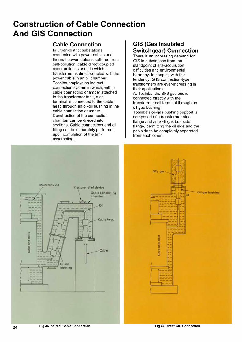
Cable Connection In urban-district substations connected with power cables and thermal power stations suffered from salt-pollution, cable direct-coupled construction is used in which a transformer is direct-coupled with the power cable in an oil chamber. Toshiba employs an indirect connection system in which, with a cable connecting chamber attached to the transformer tank, a coil terminal is connected to the cable head through an oil-oil bushing in the cable connection chamber. Construction of the connection chamber can be divided into sections. Cable connections and oil filling can be separately performed upon completion of the tank assembling.
GIS (Gas Insulated Switchgear) Connection There is an increasing demand for GIS in substations from the standpoint of site-acquisition difficulties and environmental harmony. In keeping with this tendency, G IS connection-type transformers are ever-increasing in their applications. At Toshiba, the SF6 gas bus is connected directly with the transformer coil terminal through an oil-gas bushing. Toshiba's oil-gas bushing support is composed of a transformer-side flange and an SF6 gas bus-side flange, permitting the oil side and the gas side to be completely separated from each other.
Fig.46 Indirect Cable Connection Fig.47 Direct GIS Connection24
Transportation
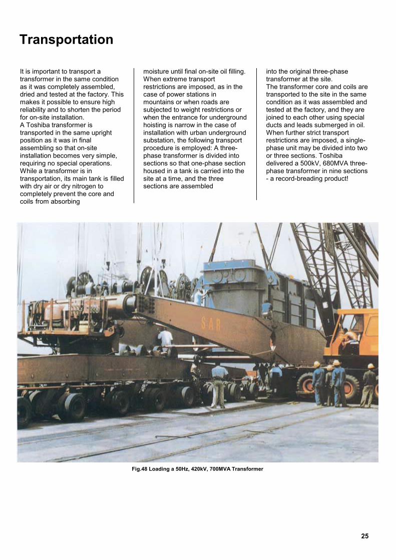
It is important to transport a transformer in the same condition as it was completely assembled, dried and tested at the factory. This makes it possible to ensure high reliability and to shorten the period for on-site installation. A Toshiba transformer is transported in the same upright position as it was in final assembling so that on-site installation becomes very simple, requiring no special operations. While a transformer is in transportation, its main tank is filled with dry air or dry nitrogen to completely prevent the core and coils from absorbing
moisture until final on-site oil filling. When extreme transport restrictions are imposed, as in the case of power stations in mountains or when roads are subjected to weight restrictions or when the entrance for underground hoisting is narrow in the case of installation with urban underground substation, the following transport procedure is employed: A three-phase transformer is divided into sections so that one-phase section housed in a tank is carried into the site at a time, and the three sections are assembled
into the original three-phase transformer at the site. The transformer core and coils are transported to the site in the same condition as it was assembled and tested at the factory, and they are joined to each other using special ducts and leads submerged in oil. When further strict transport restrictions are imposed, a single-phase unit may be divided into two or three sections. Toshiba delivered a 500kV, 680MVA three-phase transformer in nine sections - a record-breading product!
Fig.48 Loading a 50Hz, 420kV, 700MVA Transformer
25
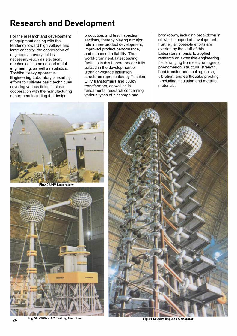
Research and Development For the research and development of equipment coping with the tendency toward high voltage and large capacity, the cooperation of engineers in every field is necessary -such as electrical, mechanical, chemical and metal engineering, as well as statistics. Toshiba Heavy Apparatus Engineering Laboratory is exerting efforts to cultivate basic techniques covering various fields in close cooperation with the manufacturing department including the design,
production, and test/inspection sections, thereby playing a major role in new product development, improved product performance, and enhanced reliability. The world-prominent, latest testing facilities in this Laboratory are fully utilized in the development of ultrahigh-voltage insulation structures represented by Toshiba UHV transformers and 500kV transformers, as well as in fundamental research concerning various types of discharge and
breakdown, including breakdown in oil which supported development. Further, all possible efforts are exerted by the staff of this Laboratory in basic to applied research on extensive engineering fields ranging from electromagnetic phenomenon, structural strength, heat transfer and cooling, noise, vibration, and earthquake proofing -including insulation and metallic materials.
Fig.49 UHV Laboratory
Fig.50 2300kV AC Testing Facilities Fig.51 6000kV Impulse Generator 26
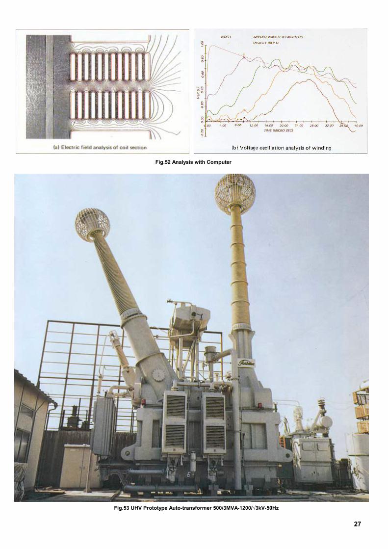
Fig.52 Analysis with Computer
Fig.53 UHV Prototype Auto-transformer 500/3MVA-1200/√3kV-50Hz
27

1T
OLBHBJR
●●
Toshiba International Corporation:San Francisco, Houston, Vancouver Toshiba International CorporationPty. Ltd.: Sydney, Melbourne Toshiba International Company Limited: London
TTTT
6814-7 99-4 C1
-1, SHIBAURA 1-CHOME, MINATO-KU, TOKYO, 105-8011, JAPAN EL: 03(3457)3612 FAX: 03(5444)94196
verseas Office:ondon, Moscow, Vienna, eijing Shanghai, Guangzhou, ong Kong, New Delhi, angkok, Taipei, Manila, akarta, Colombia, io de Janeiro, Buenos Aires
For further information, please contact your nearest Toshiba Liaison Representational or International Operations-Energy System. The data given in this catalog are subject to change without notice.
OSHIBAOSHIBAOSHIBAOSHIBA