Embed Size (px)
Citation preview

GEA33861 February 2019
GE Power
© General Electric Company, 2019. GE proprietary information and confidential information.
POWER TO GAS: HYDROGEN FOR POWER GENERATIONFuel Flexible Gas Turbines as Enablers for a Low or Reduced Carbon Energy Ecosystem
Dr. Jeffrey Goldmeer
ABSTRACTThe desire to reduce carbon emissions from traditional power generation assets is driving an increase in power production from renewables. However, an issue with large increases in renewable power generation is the lack of dispatchability; without adding storage or firming capability, increases in renewables can strain a power grid. Gas turbines can be used to fill this gap, but there are questions about the long-term use of these assets in a carbon-free energy ecosystem.
An advantage for gas turbines is that they are able to operate on hydrogen(H2), which does not provide any carbon emissions when combusted. This includes both new gas turbines and existing units which can be converted to operation on a high H2 fuel.
This paper will provide an update on how gas turbines can support a low or reduced carbon electrical grid by operating on a wide variety of lower carbon fuels, including current hydrogen capabilities of GE gas turbines, requirements for upgrading existing turbines for operation on hydrogen fuels, and potential future technology options.
2 © General Electric Company, 2019. GE proprietary information and confidential information.
POWER TO GAS: HYDROGEN FOR POWER GENERATION GEA33861
INTRODUCTIONThe desire to reduce carbon emissions from power generation is creating a fundamental paradigm shift in the power generation industry. A direct result of this shift is an acceleration in the installed capacity of renewable power sources, including solar and wind. For example, ~86% or 21 GW of the new power installations in Europe in 2016 were from renewable sources [1]. With the large and rapid increases in installed capacity of renewable sources, there are concerns about the need to dispatch large blocks of power quickly to provide grid stability given the interruptible nature of some renewables. In these situations, the grid regulating agencies used dispatchable power generation assets (i.e. gas turbine power plants) to balance supply and demand.
Although these assets are dispatchable and needed for grid regulation, there are questions being asked about utilization of these plants in a potential future, carbon-free energy ecosystem. There are multiple approaches for low-carbon or carbon-free fuels, including the use of hydrogen for power generation [2]. Modern gas turbines are capable of operating on a wide range of H2 concentrations, with multiple commercial power plants having considerable experience. Thus, gas turbines operating on hydrogen could provide the needed grid firming while at the same time generating significantly less carbon dioxide (CO2) emissions.
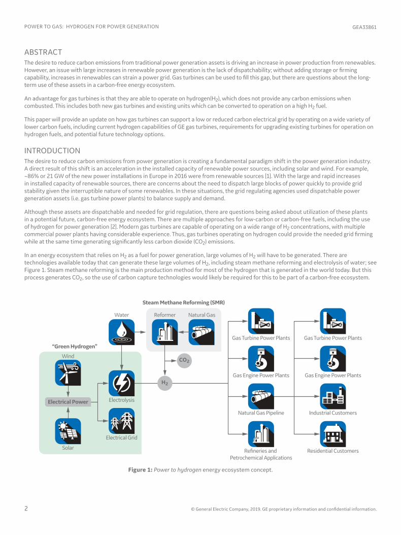
In an energy ecosystem that relies on H2 as a fuel for power generation, large volumes of H2 will have to be generated. There are technologies available today that can generate these large volumes of H2, including steam methane reforming and electrolysis of water; see Figure 1. Steam methane reforming is the main production method for most of the hydrogen that is generated in the world today. But this process generates CO2, so the use of carbon capture technologies would likely be required for this to be part of a carbon-free ecosystem.
Figure 1: Power to hydrogen energy ecosystem concept.
Gas Turbine Power PlantsGas Turbine Power Plants
Gas Engine Power PlantsGas Engine Power Plants
Industrial Customers
Residential Customers
Natural Gas Pipeline
Re�neries and Petrochemical Applications
Wind
Solar
Water
Electrolysis
Electrical Grid
Electrical Power
H2
Natural GasReformer
CO2
Steam Methane Reforming (SMR)
“Green Hydrogen”

© General Electric Company, 2019. GE proprietary information and confidential information. 3
GEA33861 POWER TO GAS: HYDROGEN FOR POWER GENERATION
Electrolysis of water is not a new concept. But using it to generate the volumes of hydrogen required for power generation will require a large amount of energy, which could dramatically increase the cost of the hydrogen and the resulting power. An alternative solution for generating the large volumes might be to generate H2 from an electrolysis using renewable energy. This solution represents a fundamental paradigm shift in the power generation industry; the rapid increase in installed capacity of renewable sources is creating excess power, leading to curtailment and in some situations creating a negative impact on electricity prices. Using curtailed power from renewable sources could potentially supply the power needed to generate what is being called “green H2”, hydrogen generated from electrolysis using renewable energy.
This paper will examine the concept of producing and using hydrogen in gas turbines as an enabler for a reduced carbon (or carbon free) energy ecosystem.
PRODUCTION OF HYDROGENHydrogen can be generated from a variety of feedstocks and chemical processes, as shown in Figure 2. These include (but are not limited to) photosynthesis using algae, steam methane reforming (SMR) of natural gas, partial oxidation of crude oil, gasification of coal, and electrolysis of water. The next sections will provide details on steam methane reforming and electrolysis as potential pathways to generating hydrogen for power generation.
Generating hydrogen: steam methane reformingToday, most of the hydrogen generated in the world comes from steam methane reforming. Much of this hydrogen is used in the production of ammonia for fertilizers or in the production of petrochemicals. In this process, natural gas (methane) is reacted with water with a catalyst and heat to generate H2 and CO2 via two reactions [4], [5]:
CH4 + H2O → CO + 3H2 (1)
CO + H2O → CO2 + H2 (2)
Based on these equations, for each mole of methane used, one mole of CO2 and four moles of H2 are produced. Using the molecular weights listed in Table 1, for each kg of methane consumed, ½ kilogram of H2 and 2.75 kilograms of CO2 are produced. (For every kilogram of H2 produced, 5.5 kilograms of CO2 are generated.) Putting this into perspective of the volumes required for power generation, a single 6B.03 gas turbine operating 8,000 hours per year would consume approximately 33 million kg of H2 (per year). If the hydrogen was generated via SMR, this would produce ~178,000 metric tonnes of CO2 per year. Table 2 shows the rate of CO2 production when scaled to hydrogen production for some gas turbine platforms.
Natural Gas Solar Wind Geothermal
Biomass Nuclear Fossil Fuels Electricity
SOURCES OF ENERGYHydrogen can be produced using diverse, domestic resources.
HYDROGENA clean, �exible energy carrier.
PRODUCTION PATHWAYSHydrogen can be produced using a number of di�erent processes.
Electrolysis Biological Direct SolarWater Splitting
Steam MethaneReforming
Figure 2: Pathways to hydrogen [3].

4 © General Electric Company, 2019. GE proprietary information and confidential information.
POWER TO GAS: HYDROGEN FOR POWER GENERATION GEA33861
Elements, Molecules Formula Molecular Weight(grams/mole)
Hydrogen H2 2
Carbon C 12
Oxygen O2 32
Methane CH4 16
Water H2O 18
Carbon Monoxide CO 28
Carbon Dioxide CO2 44
Table 1: Molecular weight of elements and molecules.
Gas Turbine Output†MW
Heat Input†GJ/hour
(MMBTU/hour)
100% H2 Flow Rate
kg/hour
CO2 Generated
kg/hour Metric tonnes/year
GE-10 11.2 129 (122) ~1,140 ~6,250 ~50,000
TM2500 34.3 350 (332) ~3,120 ~16,950 ~135,600
6B.03 44.0 473 (448) ~4,170 ~22,900 ~183,000
6F.03 87 857(813) ~7,550 ~41,500 ~332,000
7F.05 243 2,197(2,083) ~19,500 ~106,500 ~852,000
9F.04 288 2,677 (2,537) ~23,600 ~130,000 ~1,040,900
9HA.02 557 4,560(4,322) ~40,200 221,000 ~1,800,000
Table 2: Steam methane reforming requirements supporting 100% hydrogen operation.
† ISO conditions operating on natural gas
Although generating hydrogen via SMR creates carbon dioxide, there are a number of projects that are considering this pathway to generating hydrogen by combining it with carbon capture and sequestration (CCS). Examples of projects considering generating hydrogen with SMR are the H21 Leeds City Gate and the Magnum Vattenfall project. In the case of the City of Leeds project [6], it is estimated that 2.4 billion m3 of hydrogen would be produced annually to provide heat and electricity to roughly 660,000 people. As part of this system, a 90% carbon capture system is being considered which will capture approximately 1.5 million tonnes of CO2 annually. The Magnum Vattenfall project in the Netherlands has proposed to upgrade an existing gas turbine to operate on 100% hydrogen [7], [8]. The plan as proposed is to generate the hydrogen from natural gas, and the resulting CO2 will be captured and stored in underground bunkers. Open questions remain on transporting the hydrogen and storing the hydrogen at the power plant.
The challenge of these projects is the goal of creating carbon-free power using a technology that requires large scale sequestration of CO2. But, there are technologies that can generate H2 without generating CO2.
Generating hydrogen: electrolysis of waterOne established method for generating hydrogen is electrolysis of water. Splitting water follows the following chemical reaction:
H2O → H2 + ½ O2 (3)

Based on this reaction for each mole of water used, 1 mole of hydrogen and one-half mole of oxygen are generated. Using the molecular weights listed in Table 1, each gram of water used will generate 0.11 grams of hydrogen and 0.89 grams of oxygen. (Notice that the total mass is conserved.) In other words, generating 1 gram (1 kg) of hydrogen requires 9 grams (9 kg) of water, assuming no losses in the electrolysis process. With this information, it is possible to compute the water required to support the power to hydrogen concept. Table 3 shows the water required to generate enough hydrogen to operate different gas turbines on 100% hydrogen. For reference, an Olympic size swimming pool contains 2500 m3 of water; this means that an electrolyzer generating hydrogen for a GE-10 would use an equivalent volume of water in approximately 250 hours (just over 10 days). Supplying hydrogen for a 9F.04 would use an Olympic pool of water every 12 hours.
Operating a gas turbine on a hydrogen/natural gas blend instead of 100% hydrogen reduces not only the hydrogen flows, but the amount of water required to generate the hydrogen. For example, operating a 9F.04 gas turbine on a blend of 5% (by volume) hydrogen with natural gas would require ~ 3.2 m3/hour (~840 gallons/hour) of water to generate the required hydrogen.
Electrolysis also requires electrical power to split apart the water molecules. The amount of power required is defined by the higher heating value (HHV) of hydrogen divided by the electrolyzer system efficiency [9]:
“Electrolyzer Power” = HHV/η (4)
The HHV for hydrogen is 12,756.2 kJ/Nm3 (141,829.6 kJ/kg); this is equivalent to 3.54 kWh/Nm3 (39.39 kWh/kg). Assuming a 65% efficiency electrolyzer system, which represents commercially available technology, transforming water to hydrogen requires 5.45 kWh/m3 (60.61 kWh/kg). Using the GE-10 gas turbine as an example, per Table 3 the hydrogen flow rate is ~11,700 m3/ hour. To generate enough H2 to operate the GE-10 for 24 hours, the electrolyzer system would consume ~1.54 GWh of electricity. The electric power requirements for multiple turbines are shown in Table 3. Increasing the electrolyzer efficiency will reduce some of the power needs, as would operating the gas turbine on a blend of hydrogen and natural gas.
Thus, large sources of power and water will be required to create a hydrogen ecosystem using electrolysis of water. The next section examines the availability of renewable power to support this concept.
© General Electric Company, 2019. GE proprietary information and confidential information. 5
GEA33861 POWER TO GAS: HYDROGEN FOR POWER GENERATION
Gas Turbine Output†MW
Heat Input†GJ/hour
(MMBTU/hour)
100% H2 Flow Rate
m3/hour (ft3/hour)
Water Required to Generate H2
m3/hour (gallons/hour)
Electrolysis Power Required††
GWh
GE-10 11.2 129 (122)
~11,700 (~446,000)
~10 (~3,700) ~500
TM2500 34.3 350 (332)
~31,800 (~1,210,800)
~27 (~7,300) ~1,500
6B.03 44.0 473 (448)
~ 43,000 (~1,635,900)
~37 (~9,900) ~2,000
6F.03 87 857(813)
~78,000(2,970,000)
~68(~17,950) ~3,600
7F.05 243 2,197(2,083)
~200,000(~7,600,000)
~174(~46,000) ~9,400
9F.04 288 2,677(2,537)
~243,500 (~9,266,900)
~212(~56,000) ~11,400
9HA.02 557 4,560(4,322)
~415,000(~15,786,400)
~361(~95,500) ~19,500
Table 3: Electrolysis requirements supporting 100% hydrogen operation.
† ISO conditions operating on natural gas†† Power required for electrolysis to supply H2 flow for gas turbine to operate on 100% H2 for 8000 hours

6 © General Electric Company, 2019. GE proprietary information and confidential information.
POWER TO GAS: HYDROGEN FOR POWER GENERATION GEA33861
Renewable power for hydrogen generationTo support the concept of generating hydrogen with electrolysis using renewable power (also known as power to hydrogen), a large amount of carbon-free power will be required. The good news is that the global drive for carbon-free power has led to an unprecedented acceleration in power production from renewables; this is evident in statistics on power generated from renewable sources. As shown in figure 3, the electricity generated in Europe from renewables, including wind and solar, increased from ~12.6 terawatt hours (TWh) in 1990 to more than 570 TWh in 2016 [10].
Not only was the total (or absolute) amount of power from renewable sources increasing, but the percentage of power from renewable sources relative to total power on the grid was also increasing. Table 4 shows the growth in renewables in multiple countries in Europe between 2004 and 2016. It is interesting to note that many of the countries with the smallest increase in renewable penetration (i.e. Iceland, Sweden, and Norway) already had high rates of electricity generated from renewable sources in 2004. This growth in installed renewable capacity continued in 2017. According to Wind Europe, an additional 6 GW of solar was installed, along with 15.6 GW of wind power capacity, in 2017. The installed wind power capacity in Europe is now estimated at 169 GW [11].
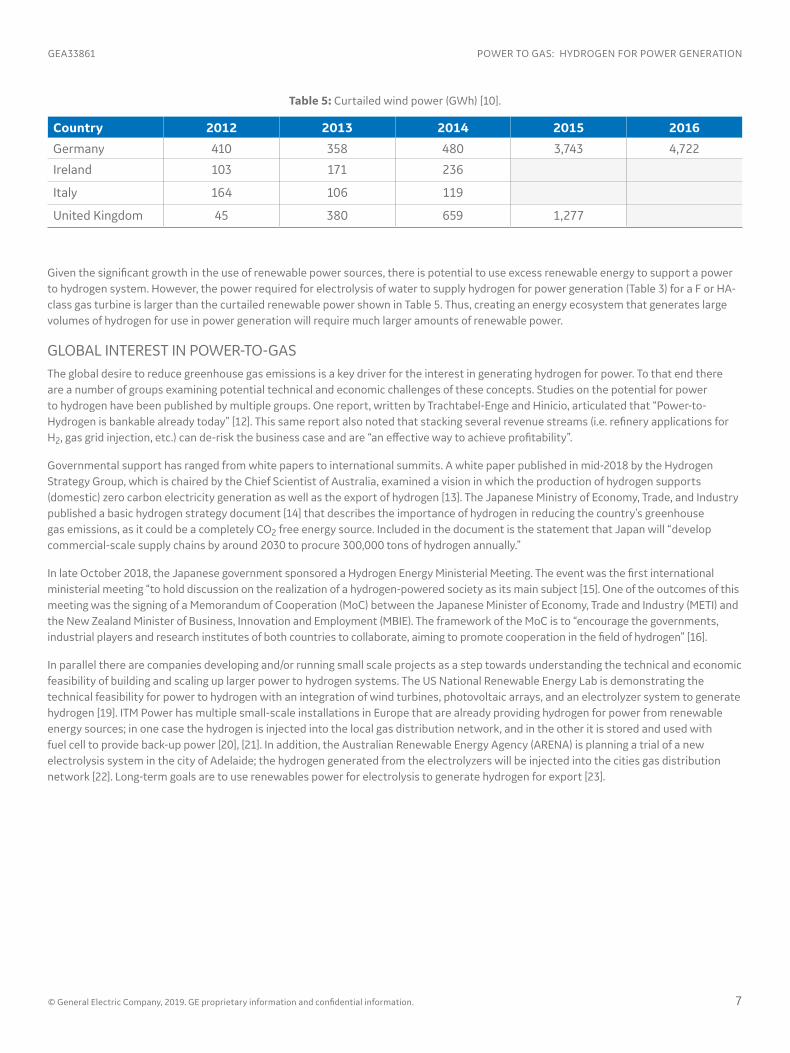
A key to using renewable sources to generate hydrogen is having excess power, above and beyond that which is needed for electrical demand. One way to gauge this capability is with curtailment of renewable sources. Table 5 shows wind curtailment for Germany, Ireland, Italy, and the UK between 2012 and 2016; data was not available for all countries in all years.
1990 1992 1994 1996 1998 2000 2002 2004 2006 2008 2010 2012 2014 20160
100
200
300
400
500
600
ELEC
TRIC
ITY
GEN
ERAT
ION
FRO
MRE
NEW
ABL
E SO
URC
ES (T
WH
)
Wood and Other Solid Biomass Biogas and Bioliquids Solar PowerWind Power
Figure 3: Electricity generation from renewable sources in Europe (TWh) [10].
Country 2004 Share (%) 2016 Share (%) Percent Growth in Renewables 2004-2016
United Kingdom 1.1 9.3 745%
Netherlands 2.0 6.0 200%
Italy 6.3 17.4 176%
Germany 5.8 14.8 155%
Denmark 14.9 32.2 116%
Spain 8.4 17.3 106%
France 9.5 16.0 68%
Iceland 58.9 72.6 23%
Sweden 38.7 53.8 39%
Norway 58.1 69.4 19%
Table 4: Increase in share of energy from renewable sources [10].
© General Electric Company, 2019. GE proprietary information and confidential information. 7
GEA33861 POWER TO GAS: HYDROGEN FOR POWER GENERATION
Country 2012 2013 2014 2015 2016
Germany 410 358 480 3,743 4,722
Ireland 103 171 236
Italy 164 106 119
United Kingdom 45 380 659 1,277
Table 5: Curtailed wind power (GWh) [10].
Given the significant growth in the use of renewable power sources, there is potential to use excess renewable energy to support a power to hydrogen system. However, the power required for electrolysis of water to supply hydrogen for power generation (Table 3) for a F or HA-class gas turbine is larger than the curtailed renewable power shown in Table 5. Thus, creating an energy ecosystem that generates large volumes of hydrogen for use in power generation will require much larger amounts of renewable power.
GLOBAL INTEREST IN POWER-TO-GASThe global desire to reduce greenhouse gas emissions is a key driver for the interest in generating hydrogen for power. To that end there are a number of groups examining potential technical and economic challenges of these concepts. Studies on the potential for power to hydrogen have been published by multiple groups. One report, written by Trachtabel-Enge and Hinicio, articulated that “Power-to-Hydrogen is bankable already today” [12]. This same report also noted that stacking several revenue streams (i.e. refinery applications for H2, gas grid injection, etc.) can de-risk the business case and are “an effective way to achieve profitability”.
Governmental support has ranged from white papers to international summits. A white paper published in mid-2018 by the Hydrogen Strategy Group, which is chaired by the Chief Scientist of Australia, examined a vision in which the production of hydrogen supports (domestic) zero carbon electricity generation as well as the export of hydrogen [13]. The Japanese Ministry of Economy, Trade, and Industry published a basic hydrogen strategy document [14] that describes the importance of hydrogen in reducing the country’s greenhouse gas emissions, as it could be a completely CO2 free energy source. Included in the document is the statement that Japan will “develop commercial-scale supply chains by around 2030 to procure 300,000 tons of hydrogen annually.”
In late October 2018, the Japanese government sponsored a Hydrogen Energy Ministerial Meeting. The event was the first international ministerial meeting “to hold discussion on the realization of a hydrogen-powered society as its main subject [15]. One of the outcomes of this meeting was the signing of a Memorandum of Cooperation (MoC) between the Japanese Minister of Economy, Trade and Industry (METI) and the New Zealand Minister of Business, Innovation and Employment (MBIE). The framework of the MoC is to “encourage the governments, industrial players and research institutes of both countries to collaborate, aiming to promote cooperation in the field of hydrogen” [16].
In parallel there are companies developing and/or running small scale projects as a step towards understanding the technical and economic feasibility of building and scaling up larger power to hydrogen systems. The US National Renewable Energy Lab is demonstrating the technical feasibility for power to hydrogen with an integration of wind turbines, photovoltaic arrays, and an electrolyzer system to generate hydrogen [19]. ITM Power has multiple small-scale installations in Europe that are already providing hydrogen for power from renewable energy sources; in one case the hydrogen is injected into the local gas distribution network, and in the other it is stored and used with fuel cell to provide back-up power [20], [21]. In addition, the Australian Renewable Energy Agency (ARENA) is planning a trial of a new electrolysis system in the city of Adelaide; the hydrogen generated from the electrolyzers will be injected into the cities gas distribution network [22]. Long-term goals are to use renewables power for electrolysis to generate hydrogen for export [23].
8 © General Electric Company, 2019. GE proprietary information and confidential information.
POWER TO GAS: HYDROGEN FOR POWER GENERATION GEA33861
Property Units Methane Hydrogen
Formula CH4 H2
Molecular Weight gram/mol 16 2
LHV (per volume)MJ/Nm3 35.8 10.8
BTU/scf 911.6 274.7
LHV (per mass)MJ/kg 50 120
BTU/lb 21,515 51,593
Table 6: Comparison of fuel properties.
CARBON EMISSION REDUCTION WITH HYDROGENHydrogen (H2) is a clean burning fuel that does not produce any carbon emissions as it does not include any carbon (C). In a complete and balanced combustion reaction, which is the opposite of splitting water (Equation 3), hydrogen would produce only water:
H2 + ½ O2 → H2O (5)
Using 100% hydrogen as fuel for a gas turbine will lead to a significant reduction in carbon dioxide (CO2) emissions relative to operation on natural gas or other hydrocarbon fuels. CO2 emissions attributed to the fuel will be zero, although the plant will still emit a very small amount of CO2 as there is approximately 0.04% (by volume) CO2 in the air that will be emitted with the products of combustion. For example, a gas turbine operating on 100% (by volume) H2 fuel will see a CO2 reduction of ~99% relative to the CO2 emission on 100% methane.
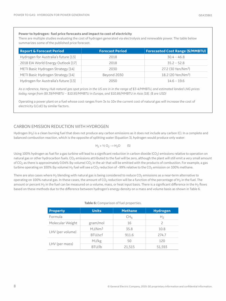
There are also cases where H2 blending with natural gas is being considered to reduce CO2 emissions as a near-term alternative to operating on 100% natural gas. In these cases, the amount of CO2 reduction will be a function of the percentage of H2 in the fuel. The amount or percent H2 in the fuel can be measured on a volume, mass, or heat input basis. There is a significant difference in the H2 flows based on these methods due to the difference between hydrogen’s energy density on a mass and volume basis as shown in Table 6.
Report & Forecast Period Forecast Period Forecasted Cost Range ($/MMBTU)
Hydrogen for Australia’s future [13] 2018 30.4 – 46.8
2018 EIA World Energy Outlook [17] 2018 35.2 – 52.8
METI Basic Hydrogen Strategy [14] 2030 27.2 (30 Yen/Nm3)
METI Basic Hydrogen Strategy [14] Beyond 2030 18.2 (20 Yen/Nm3)
Hydrogen for Australia’s future [13] 2050 14.6 – 19.6
Power to hydrogen: fuel price forecasts and impact to cost of electricityThere are multiple studies evaluating the cost of hydrogen generated via electrolysis and renewable power. The table below summarizes some of the published price forecast.
As a reference, Henry Hub natural gas spot prices in the US are in in the range of $3-4/MMBTU, and estimated landed LNG prices today range from $9.39/MMBTU – $10.95/MMBTU in Europe, and $10.86/MMBTU in Asia [18]. ($ are USD)
Operating a power plant on a fuel whose cost ranges from 3x to 10x the current cost of natural gas will increase the cost of electricity (LCoE) by similar factors.

Typically, flows into a gas turbine are quoted on a volumetric basis, but the key factor in determining emissions for a fuel blend is the relative heat input from the fuel constituents, especially as methane and hydrogen have very different energy densities. This is an important distinction as adding small amounts of hydrogen to the fuel (on a volumetric basis) will have a smaller impact on carbon dioxide emission reduction. Figure 4 shows the relationship between volumetric flow and heat input (mass flow) for a system using a blend of methane and hydrogen.
© General Electric Company, 2019. GE proprietary information and confidential information. 9
GEA33861 POWER TO GAS: HYDROGEN FOR POWER GENERATION
100 90 80 70 60 50 40 30 20 10 0
0 10 20 30 40 50 60 70 80 90 100
0
20
40
60
80
100
METHANE (VOLUME %)
HYDROGEN (VOLUME %)
PERC
ENT
RED
UC
TIO
N IN
CO
2
100 90 80 70 60 50 40 30 20 10 0
0 10 20 30 40 50 60 70 80 90 100
0
20
40
60
80
100
0
20
40
60
80
100
% C
H4
(BY
HEA
T IN
PUT)
% H
2 (B
Y H
EAT
INPU
T)
% CH4 (BY VOLUME FLOW)
% H2 (BY VOLUME FLOW)
CH4H2
Figure 5: Relationship between CO2 emissions and hydrogen/methane fuel blends (volume %).
Figure 4: Relationship between mass flow (heat input) and volumetric flow for a methane/hydrogen fuel mix.
Using this information, the relationship between the amount of H2 in the fuel (by volume) and CO2 emission reduction can be defined; as shown in Figure 5 this relationship is clearly non-linear. The gas turbine requires a constant heat input and since H2 has a lower volumetric energy density, a blend on a heat input basis contains less hydrogen (relative to a blend on a volumetric basis). As an example, a 9F.04 gas turbine operating on methane at ISO conditions will emit ~38.8 kg/sec (~86 pounds/sec) of CO2. Switching this turbine to fuel that is a 5% / 95% (by volume) blend of hydrogen and methane requires the same heat input, but due to the difference between mass and volumetric energy density of hydrogen, this ends up as a 0.65% / 99.35% blend of hydrogen and methane on a heat input basis. This results in a CO2 emission of ~38.2 kg/second (~84.3 pounds/sec), which is roughly a reduction of ~1.5% in CO2 emissions. Taking this one step further, to attain a 50% reduction in CO2 emissions a blend that is ~75% (by volume) hydrogen would be required.
Instead, if the flows are set as a percentage of the turbine heat input, the relationship between H2 and CO2 reduction is linear as shown in Figure 6. To attain a 50% reduction in CO2 emissions requires a blend that is 50% hydrogen and 50% methane (by heat content).
Understanding the magnitude of CO2 emission reduction relative to H2 content in the fuel is a key step in evaluating the value of a potential power to hydrogen system. However, one must also understand the technical challenges that accompany the use of hydrogen.

10 © General Electric Company, 2019. GE proprietary information and confidential information.
POWER TO GAS: HYDROGEN FOR POWER GENERATION GEA33861
THE CHALLENGES OF HYDROGENAlthough operating on hydrogen can lead to lower CO2 emissions, there are challenges that need to be understood given the differences between hydrogen and many traditional hydrocarbon fuels. This section provides a summary of some key combustion issues.
Heating valueThe lower heating value (LHV) of hydrogen (as was shown in Table 6) is 10.8 MJ/Nm3 (274.7 BTU/scf) or 120 MJ/kg (51,593 BTU/lb). In comparison, the LHV of 100% methane is 35.8 MJ/Nm3 (911.6 BTU/scf) or 50 MJ/kg (21,515 BTU/lb). On a mass basis, hydrogen is 2x more energy dense that methane. But, on a volume basis, hydrogen is one third less energy dense than methane. Therefore, it takes 3x more volume flow of hydrogen to provide the same heat (energy) input as methane. Thus, operating a gas turbine on 100% hydrogen requires a fuel accessory system configured for the required flow rates.
Flame speedIn a combustion reaction, the flame velocity or flame speed is the velocity at which the unburned gases propagate into the flame. The flame speed of hydrogen is an order of magnitude faster than many hydrocarbon fuels. Table 7 lists the flame speeds for a set of common hydrocarbon fuels. From a gas turbine perspective, flame speed is an important property used in determining if a combustor may have issues with the flame propagating upstream from the combustion zone into the premixing zone (near the fuel nozzles).
Fuel Formula Laminar Flame Speed (cm/sec) at Stoichiometric Conditions
Hydrogen H2 170
Methane CH4 38.3
Ethane C2H6 40.6
Propane C3H8 42.3
Carbon Monoxide CO 58.8
Table 7: Laminar flame speed of common fuels [24].
100 90 80 70 60 50 40 30 20 10 0
0 10 20 30 40 50 60 70 80 90 100
0
20
40
60
80
100
PERC
ENT
RED
UC
TIO
N IN
CO
2
METHANE (% BY HEAT CONTENT)
HYDROGEN (% BY HEAT CONTENT)
Figure 6: Relationship between CO2 emissions and hydrogen/methane fuel blends (% heat input).

© General Electric Company, 2019. GE proprietary information and confidential information. 11
GEA33861 POWER TO GAS: HYDROGEN FOR POWER GENERATION
GAS TURBINE COMBUSTION TECHNOLOGYThe ability of gas turbine to operate on a high hydrogen fuel requires a combustion system that can deal with the specific nature of this fuel. Typical dry low NOx (DLN) combustion systems can handle some amount of hydrogen, but due the fundamental differences between hydrogen and methane previously discussed, these combustion systems are not able to handle moderate to high levels of hydrogen. Instead, combustion systems that are configured to operate on fuels with higher concentrations of hydrogen are utilized. GE offers combustion systems for both Aeroderivative and Heavy-Duty gas turbines that are capable of operating with increased levels of H2, ranging from 5% (by volume) to 100% (by volume). The various combustion systems capable of handling higher concentrations of H2 are shown in Figure 8.
Aeroderivative Gas Turbines Heavy-Duty Gas Turbines
Figure 8: High hydrogen combustion systems.
SAC MNQCSingle Nozzle
Typically, combustion systems are configured to operate on a set of fuels that have a defined range of flame speeds. Due to the significant difference in the flame speeds of methane and hydrogen, combustion systems configured for operating on methane (or natural gas) may not be suitable for operating on a high hydrogen fuel. In many cases, operating on a high hydrogen fuel requires a combustor specifically configured for the different combustion conditions. (See Combustion Technology section.)
SafetyThere are additional operational challenges with hydrogen that relate to overall safety. First, a hydrogen flame has low luminosity and is therefore hard to see visually, as shown in Figure 7. This requires flame detection systems specifically configured for hydrogen flames. Secondly, hydrogen can diffuse through seals that might be considered airtight or impermeable to other gases. Therefore, traditional sealing systems used with natural gas may need to be replaced with welded connections or other appropriate components. Thirdly, hydrogen is more flammable than methane; the lower flammability limit for methane (in air) is 5%, while for hydrogen it is 4% [25]. Therefore, hydrogen leaks could create increased safety risks requiring changes to plant procedures, safety / exclusions zones, etc. In addition, there may be other plant level safety issues that merit review [26].
Figure 7: Comparison of natural gas and hydrogen flames.
DLN 2.6e

12 © General Electric Company, 2019. GE proprietary information and confidential information.
POWER TO GAS: HYDROGEN FOR POWER GENERATION GEA33861
Single annular combustorGE’s Aeroderivative gas turbines can be configured with a single annular combustor (SAC), which can operate on a variety of fuels, including process fuels and fuel blends with hydrogen. There are over 2,600 gas turbines configured with this combustion system; these units have accumulated more than 100 million fired hours on a variety of fuels. Depending on the specific Aeroderivative gas turbine model, SAC combustors can handle hydrogen concentrations from 30% (by volume) up to 85% (by volume).1
Single nozzle and multi nozzle combustorsGE’s Heavy-Duty gas turbines have two combustor configurations capable of operating on fuels with higher H2 content. The Single Nozzle (SN) or standard combustor is available on B and E-class turbines. The Multi-Nozzle Quiet Combustor (MNQC) is available for multiple E and F-class gas turbines. Combined these combustion systems have been installed on more than 1,700 gas turbines, and have accumulated more than 3.5 million fired hours on a variety of low calorific value fuels, including syngas, steel mill gases, refinery gases, etc.
During the 1990’s GE evaluated the use of the MNQC combustor to operate on high hydrogen fuels [27]. The hydrogen concentration of the fuels examined ranged from ~43.5% up to ~89%; the remaining constituents in the fuel were inert gases, i.e. nitrogen and water vapor. The program evaluated the impact on NOx emissions, combustion dynamics and combustion metal temperatures. The test results demonstrated the feasibility of burning hydrogen as the only combustible (up to 90% by volume of the total fuel) in GE’s MNQC combustion system.
Today, GE is able to quote hydrogen levels up to ~90-100% (by volume) for applications with the MNQC combustor or single nozzle combustor1.
Dry low emission (DLE) and dry low NOx (DLN) combustorsDLE and DLN combustion systems are capable of operating with limited amounts of hydrogen in the fuel. The DLE combustor, which is found on GE’s Aeroderivative gas turbines, is limited to 5% (by volume) hydrogen. The DLN1 combustion system, which is available on GE’s 6B, 7E, and 9E gas turbines, is capable of operating with up to 33% (by volume) hydrogen when blended with natural gas. GE’s DLN 2.6+ combustors are capable of operating on hydrogen levels as high as ~15% (by volume)1. The associated fuel systems for these combustors are typically only configured for a maximum of 5% (by volume) hydrogen and would require upgrading to safely operate at higher hydrogen concentrations.
Next generation high H2 combustion systemAs part of the US Department of Energy’s Advanced IGCC/Hydrogen Gas Turbine program, GE developed a low-NOx hydrogen combustion system2. This new combustion system was based on the operating principle of small scale jet-in-crossflow mixing of the fuel and air streams [28]. The miniaturized tubes (see Figure 9a) function as “fast” mixers, enabling premixed combustion for gaseous fuels with higher reactivity (ethane, propane, hydrogen, etc.)
During this program, multiple pre-mixing configurations were tested at the GE Global Research Center in a single nozzle test facility as well as at GE’s Gas Turbine Technology Lab. (Information on the Greenville combustion facility is available in Reference 29). Figure 9b shows a combustor chamber with multi-tube mixers operating on a H2/N2 fuel blend.
Due to the advanced premixing capability of this technology, it became an element of GE’s DLN 2.6e combustion system, which is available on the 9HA gas turbine [30]. Due to interest in low-carbon power for future power plants, the hydrogen capability of the DLN 2.6e combustion system was evaluated. Results of preliminary testing indicated that this combustion system has entitlement to operate on fuels containing up to 50% (by volume) hydrogen.
Figure 9: (A) multi-tube mixer concept hardware, (B) combustor test of multi-tube mixers on a H2/N2 fuel blend [18].
A B
1 Hydrogen limits for a given project will be a function of gas turbine model, ambient conditions, emission requirements, and other site-specific requirements.
2 This effort was sponsored by the US Department of Energy under Cooperative Agreement DE-FC26-05NT42564.

© General Electric Company, 2019. GE proprietary information and confidential information. 13
GEA33861 POWER TO GAS: HYDROGEN FOR POWER GENERATION
GAS TURBINE EXPERIENCE WITH HYDROGENOnce hydrogen has been generated it can be utilized as a power generation fuel. Gas turbines have the capability to operate on hydrogen, supporting a variety of industrial applications, including steel mills, refineries, and petrochemical plants. GE is a world leader in gas turbine fuel flexibility, including more than 70 gas turbines that have (or continue to) operate on fuels that contain hydrogen. This fleet has accumulated more than 4 million operating hours and over 300 terawatts of power generation. This fleet also includes a set of 25 gas turbines that have operated on fuels with at least 50% (by volume) hydrogen; these units have accumulated more than one million operating hours. Figure 10 highlights some of the projects that have used fuels with varying concentrations of hydrogen over the last 20+ years. The following sections provide more details on some of these projects. Additional details can also be found in papers by Jones, et al. [31], [32] and DiCampli [33].
Hydrogen fuel blendingThere are circumstances when hydrogen is available as a by-product of an industrial or petrochemical process. But in some situations, there may not be enough hydrogen to fully load a gas turbine, so a blend of hydrogen and natural gas is generated; in these cases, traditional dry low NOx (DLN) combustion systems can be utilized. One example of this fuel blending application was at the Dow Plaquemine plant in the USA [34]. At this site, hydrogen was injected into natural gas to create a 5% / 95% (by volume) blend of hydrogen and natural gas. Figure 11 shows the blending system; after blending, the fuel gas was fed to four GE 7FA gas turbines configured with DLN 2.6 combustion systems; operation on the blended fuel started in 2010.
A second example of hydrogen fuel blending is at the Gibraltar-San Roque refinery owned by Compañia Española de Petróleos (CEPSA), one of Spain’s leading petrochemical companies. At this site a 6B.03 gas turbine is operating on a refinery fuel gas (RFG) that contains a varying amount of hydrogen. If the hydrogen level exceeds ~32% (by volume) the RFG is blended with natural gas. As of 2015, this gas turbine had operated more than 9,000 hours on this fuel [35].
1x7F IGCC (USA)
1x7F IGCC (USA)
1x6B IGCC
2x6F Refinery (USA)
2x6F Syngas Refinery (Asia)
1xGE10 High H2 (Europe)
2x9E Steel Mill (China)
2x9E Refinery (India)
1x7E IGCC (USA)
1x6B Refinery (Europe)
1x6B Refinery (Korea)
3x9E Steel Mill (Europe)
3x9E Refinery (Europe)
2x7F Syngas Coal IGCC (USA)
2xLM2500 Steel Mill (China)
1x7F Syngas IGCC (Korea)
1990 2000 2010
Figure 10: Timeline of selected projects with hydrogen fuels.

14 © General Electric Company, 2019. GE proprietary information and confidential information.
POWER TO GAS: HYDROGEN FOR POWER GENERATION GEA33861
Low calorific value fuels: steel mill gasesSteel mills produce a variety of low calorific value by-product gases, i.e. blast furnace gas (BFG) and coke oven gas (COG), that have varying amounts of hydrogen. GE has multiple heavy-duty and gas turbines operating on these fuels. Examples include multiple steel mills in Asia using COG / BFG fuel blends in GE 9E.03 gas turbines [36], [37]; Figure 12a is an example of a steel mill configured with a GE gas turbine. GE’s Aeroderivative can also operate on coke oven gas [38]; an example of the latter case is a set of LM2500+ turbines operating on a coke oven gas (COG) with approximately 60% (by volume) hydrogen; see Figure 12b. These units were commissioned in 2011 and have accumulated over 100,000 hours on COG. Combined, GE’s aero and heavy-duty gas turbines have accumulated more than one million fired hours with steel mill gases.
Low calorific value fuels: synthesis gases (syngas)The use of gasification creates a fuel known as synthesis gas (syngas) that contains a variety of gases, including hydrogen. The H2 content in these fuels can range from 20% to ~50% (by volume) depending on the feedstock (i.e. coal, refinery bottoms) and the gasification process. Multiple IGCC (integrated gasification combined cycle) plants utilizing E-class and F-class gas turbines are in commercial operation globally. Plants with GE gas turbines have accumulated more than 1.5 million operating hours. This includes the Tampa Electric Polk Power Station, Duke Edwardsport IGCC plant, and the Korea Western Power (KOWEPO) TaeAn IGCC plant.
Figure 12: (A) Frame 9E.03 operating on steel mill gases at a plant in China; (B) LM2500+ operating on high H2 coke oven gas.
A B
Figure 11: Hydrogen / natural gas blending system.

© General Electric Company, 2019. GE proprietary information and confidential information. 15
GEA33861 POWER TO GAS: HYDROGEN FOR POWER GENERATION
CONVERSION TO HIGH H2 FUELS When considering a power to hydrogen system, existing gas turbine assets should be included as part of the evaluation, as they can be converted to operation on fuels with hydrogen. An advantage to gas turbines is that they can be re-configured for operation on new fuels, including fuels with increased levels of hydrogen fuels.
Changing to a fuel with increased levels of hydrogen may require making changes to the gas turbine, gas turbine accessories, and/or the balance of plant. The magnitude of the required changes is a function of the amount of hydrogen in the fuel. If the new fuel will be a blend of hydrogen in natural gas, the required changes might be limited controls updates along with new combustor fuel nozzles. Given that there are many variations on fuel, combustor configurations, etc., the required scope must be evaluated on a case by case basis.
If the conversion is to a high hydrogen fuel, the scope could include changes to numerous gas turbine systems as shown in Figure 14. This type of fuel conversion may require switching to a new combustion system, which would require new fuel accessory piping and valves. It may also require new fuel skids, as well as enclosure and ventilation system modifications. Other changes necessitated by the safety concerns highlighted previously include upgrading to flame detectors capable of detecting H2 flames and upgrading gas sensors to models configured to detect gases with reduced levels of hydrocarbons. Aside from physical changes, switching to a high hydrogen fuel may require changes to the gas turbine controls, which might impact gas turbine performance, both output and heat rate.
Changes in the fuel may also impact the larger balance of plant scope. For example, increasing the concentration of hydrogen in the fuel may lead to significant increases in NOx emissions. There could also be a change in the exhaust energy from the gas turbine necessitating a review of HRSG limits.
Figure 13: High hydrogen fueled 6B.03 gas turbine.
High hydrogen Typically, when H2 is available in large volumes it is used in hydrotreating crude oil or in the production of other commercial products, such as fertilizers. However, there are instances where a large volume of high concentration hydrogen is available from a process where there are no other available off takers.
GE’s fleet of gas turbines installed for operation on high hydrogen fuels includes more than a dozen Frame 5 gas turbines and more than 20 6B.03 gas turbines. Many of these turbines operated on fuels with hydrogen concentrations ranging from 50% (by volume) to 80% (by volume). One example of a gas turbine operating on a high hydrogen fuel is a 6B.03 at the Daesan refinery in South Korea. This unit (Figure 13) has operated on a fuel that contains more than 70% (by volume) hydrogen for over 20 years with max H2 levels greater than 90% [39], [40]. To date the unit has accumulated more than 100,000 hours on the high hydrogen fuel. A second example of a high hydrogen turbine is at Enel’s Fusina, Italy. This plant, which was inaugurated in 2010, used a GE-10 gas turbine to produce ~11.4 MW of net electrical power operating on a fuel that was ~97.5% (by volume) hydrogen [41-43].

16 © General Electric Company, 2019. GE proprietary information and confidential information.
POWER TO GAS: HYDROGEN FOR POWER GENERATION GEA33861
CONCLUSION / SUMMARYGas turbines are capable of operating on a wide variety of fuels, including fuels with low, moderate, and high levels of hydrogen. Given the experience in the industry with hydrogen-based fuels, many of the technical questions on the viability of this fuel for power generation applications have been answered. Thus, existing gas turbine power plants should be considered a key element of any future power to hydrogen ecosystem.
ACKNOWLEDGMENTSI would like to thank Jacob Berry, Michal Bialkowski, Deb Jaqueway, Parag Kulkarni, William Lawson, and Stephen Miller at GE Power for their support in the development of this paper.
Figure 14: Potential impact of hydrogen fuel conversion on gas turbine systems.
If future fuel upgrades are part of the planning stages during the development of a new power plant, in addition to the items listed above other considerations should include plant layout space for new and/or modified fuel modules, as well as impact to major capital items, i.e. HRSG and SCR.
Regardless of the fuel, when considering a fuel conversion, there are other factors that should be evaluated; these include but are not limited to site emission limits, fuel storage, and local safety regulations. For example, there may be a requirement (or desire) to store some amount of hydrogen at site, depending on where the hydrogen is generated and potential interruptions in supply. This in turn could impact the overall plant configuration due to safety regulations regarding safety zones around hydrogen storage tanks.
NOMENCLATUREA$ Australian Dollars
BTU British Thermal Units
CH4 Methane
CO2 Carbon Dioxide
DLE Dry Low Emissions
DLN Dry Low NOx
ft3 Cubic Feet
GW Gigawatts
GWh Gigawatt-Hour
H2 Hydrogen
H2O Water
kg Kilogram
lb Pound (mass)
kWh Kilowatt Hour
Nm3 Normal Cubic Meters
m3 Cubic Meters
MMBTU Million BTU
MJ Megajoule
MW Megawatt
O2 Oxygen
scf Standard Cubic Feet
SMR Steam Methane Reforming
TWh Terawatt-hour
Enclosure Modifications:• Piping for hydrogen gas, diluent, etc.• Explosion proofing• Hazardous gas detection• Ventilation system• Fire protection
Gas Turbine Controls HRSG & SCRAccessory Modules:• High hydrogen fuel system• Diluent injection module (if required)• Air extraction modules (if required)

© General Electric Company, 2019. GE proprietary information and confidential information. 17
GEA33861 POWER TO GAS: HYDROGEN FOR POWER GENERATION
REFERENCES1. Vaughan, A. (2017), “Almost 90% of new power in Europe from renewable sources in 2016”, The Guardian, https://www.theguardian.
com/environment/2017/feb/09/new-energy-europe-renewable-sources-2016?_sm_au_=icH71r6FFm6sl06H
2. Shell Global (2018), Shell Scenarios – Sky: Meeting the goals of the Paris Agreement, www.shell.com/skyscneario
3. US Department of Energy, Office of Energy Efficiency & Renewable Energy, Hydrogen Production: Electrolysis, https://www.energy.gov/eere/fuelcells/hydrogen-production-electrolysis
4. Edwards, P.P., Kuznetsov, V.L., and David, W.I.F. (2007), “Hydrogen Energy”, Philosophical Transactions of the Royal Society A., Mathematical, Physical, and Engineering Sciences. http://rsta.royalsocietypublishing.org/content/365/1853/1043
5. Hydrogen production: natural gas reforming, Office of Energy Efficiency & Renewable Energy, US Dept. of Energy, https://www.energy.gov/eere/fuelcells/hydrogen-production-natural-gas-reforming
6. Executive Summary (2017), H21 Leeds City Gate Project, https://www.northerngasnetworks.co.uk/wp-content/uploads/2017/04/H21-Executive-Summary-Interactive-PDF-July-2016-V2.pdf
7. MHPS Will Convert Dutch CCGT to Run on Hydrogen, Power magazine, May 2018, https://www.powermag.com/mhps-will-convert-dutch-ccgt-to-run-on-hydrogen/
8. Dutch gas power plant to undergo hydrogen power conversion, Power Engineering International, https://www.powerengineeringint.com/articles/2017/07/dutch-gas-power-plant-to-undergo-hydrogen-power-conversion.html
9. National Renewable Energy Laboratory, US Department of Energy, NREL1 – Technology Brief: Analysis of current day commercial electrolyzers, https://www.nrel.gov/docs/fy04osti/36705.pdf
10. Renewable Energy Statistics, Eurostat, http://ec.europa.eu/eurostat/statistics-explained/index.php/Renewable_energy_statistics#Consumption_of_energy_from_renewable_sources
11. Wind in Power 2017, Wind Europe, https://windeurope.org/about-wind/statistics/european/wind-in-power-2017/#presentation
12. Study on early business cases for H2 in energy storage and more broadly power to H2 applications”, a report by Tractabel - ENGIE and Hinicio, June 2017, http://www.hinicio.com/file/2017/07/P2H_Full_Study_FCHJU.pdf
13. Hydrogen for Australia’s Future, Commonwealth of Australia, 2018, https://www.chiefscientist.gov.au/wp-content/uploads/HydrogenCOAGWhitePaper_WEB.pdf
14. Basic hydrogen strategy (2017), Ministry of Economy, Trade, and Industry, http://www.meti.go.jp/english/press/2017/pdf/1226_003a.pdf
15. Japan Hosts First Hydrogen Energy Ministerial Meeting, http://www.meti.go.jp/english/press/2018/1023_007.html
16. METI and New Zealand Government Sign Memorandum of Cooperation on Hydrogen, http://www.meti.go.jp/english/press/2018/1023_006.html
17. World Energy Outlook (2018), International Energy Agency, https://webstore.iea.org/world-energy-outlook-2018
18. World LNG Estimated Landed Prices, Oct-2018, US Federal Energy Regulatory Commission, https://www.ferc.gov/market-oversight/mkt-gas/overview/ngas-ovr-lng-wld-pr-est.pdf
19. National Renewable Energy Laboratory, US Department of Energy, Hydrogen: A Promising Fuel and Energy Storage Solution, https://www.nrel.gov/continuum/energy_integration/hydrogen.html
20. ITM Power, M1 Wind hydrogen fuel station, http://www.itm-power.com/project/wind-hydrogen-development-platform
21. ITM Power, Thüga Power-to-gas plant, http://www.itm-power.com/project/thuga-power-to-gas
22. Nogrady, B. (2017), “How Australia can use hydrogen to export its solar power around the world”, The Guardian, https://www.theguardian.com/sustainable-business/2017/may/19/how-australia-can-use-hydrogen-to-export-its-solar-power-around-the-world
23. Harmsen, N. (2017) “Hydrogen to be injected into Adelaide’s gas grid in ‘power-to-gas’ trial”, Australian Broadcasting Corp., http://www.abc.net.au/news/2017-08-08/trial-to-inject-hydrogen-into-gas-lines/8782956
24. Glassman, I, (1987), Combustion, 2nd edition, Academic Press.
25. Lower and Upper Explosive Limits for Flammable Gases and Vapors, Matheson Gas, https://www.mathesongas.com/pdfs/products/Lower-(LEL)-&-Upper-(UEL)-Explosive-Limits-.pdf
26. Hawksworth, S.J., et al. (2016), “Safe Operation of Combined Cycle Gas Turbine and Gas Engine Systems using Hydrogen Rich Fuels”, EVI-GTI and PIWG Joint Conference on Gas Turbine Instrumentation.
27. Todd, D. and Battista, R. (2000) “Demonstrated Applicability of Hydrogen Fuel for Gas Turbines”, Proceedings of the IChemE Gasification 4 the Future Conference, Noordwijk, the Netherlands.
28. York, W., Ziminsky, W., and Yilmaz, E. (2013) “Development and Testing of a Low NOx Hydrogen Combustion System for Heavy-Duty Gas Turbines“, Journal of Engineering for Gas Turbines and Power, ASME, vol. 135.

29. Goldmeer, J., and Citeno, J. (2013) “Combustion testing – the key to operational certainty”. Modern Power Systems, pp. 39-40.
30. GE Power (2017), DLN2.6E Product Technology, GEA33140.
31. Jones, R., Raddings, T., Dicampli, J. (2013) “Fuel Flexibility Concepts and Experience for Power Generation with Hydrogen Based Fuels”, Power-Gen Europe.
32. Jones, R., Goldmeer, J., Monetti, B. (2011) “Addressing Gas Turbine Fuel Flexibility”, GE Power, GER4601, rev B.
33. DiCampli, J. (2013), “Aeroderivative Gas Turbine Fuel Flexibility”, Power Engineering, https://www.power-eng.com/articles/print/volume-117/issue-9/features/aeroderivative-gas-turbine-fuel-flexibility.html
34. Goldmeer, J., and Rozas, T. (2012), “Burning a mixture of H2 and natural gas”, Turbomachinery International.
35. Veazey, M. (2015), “Spanish refinery achieves RFG-powered breakthrough”, Rigzone, https://www.rigzone.com/news/oil_gas/a/149516/spanish_refinery_achieves_rfgpowered_breakthrough/
36. “GE uses steel mill gases to power turbine”, Power, http://www.powermag.com/ge-uses-steel-mill-gases-to-power-turbine/
37. “Project Profile: Wuhan Steel”, Decentralized Energy, http://www.decentralized-energy.com/articles/print/volume-12/issue-5/project-files/project-profile-wuhan-steel.html
38. Dicampli, J., et al. (2012) “Aeroderivative Power Generation with Coke Oven Gas”, ASME 2012 International Mechanical Engineering Congress & Exposition, IMECE2012-89601.
39. Moliere, M., Hugonnet, N. (2004), “Hydrogen-fueled gas turbines: experience and prospects”, Power-Gen Asia.
40. Daesan units burn 95 percent hydrogen fuel, Modern Power Systems, 1999, https://www.modernpowersystems.com/features/featuredaesan-unit-burns-95-per-cent-hydrogen-fuel/
41. Balestri, M., Sigali, S., Cocchi, S., and Provenzale, M. (2008), “Low-NOx hydrogen fueled gas turbine features and environmental performances”, Power-Gen Europe.
42. “Fusina: Achieving low NOx from hydrogen combined-cycle power”, Power Engineering International, http://www.powerengineeringint.com/articles/print/volume-18/issue-9/features/fusina-achieving-low-nox-from-hydrogen-combined-cycle-power.html
43. “Hydrogen fueled combined-cycle gas turbine power plant inaugurated by Enel”, Power Engineering, https://www.power-eng.com/articles/2010/07/hydrogen-fuelled-combined-cycle.html
18 © General Electric Company, 2019. GE proprietary information and confidential information.
POWER TO GAS: HYDROGEN FOR POWER GENERATION GEA33861

* Trademark of General Electric Company© General Electric Company, 2019. GE proprietary information and confidential information.
GEA33861 (02/2019)