Embed Size (px)
Citation preview

T&R Test Equipment design and manufacture high quality test equipment for the power industry. Our
equipment is used world-wide in transmission and distribution, power equipment manufacture, maintenance and
commissioning.
It has to do the job first time, every time, so we’ve designed the units to perform and built them to last.
Our equipment will make your life easier by being uncomplicated to use and versatile in application. The market
demands that testing time is cut to a minimum so we have eliminated costly set up times by putting the engineer in
control of the equipment. The manually driven controls allow true flexibility with power at your finger tips.
You can be confident in choosing from T&R Test Equipment’s range of equipment.
Power Test Equipment for the global power industry
DC Cable Test Systems PT18-10 +/-18kV 37 PT30-10 +/-30kV 37
High Voltage AC Test Systems
KV5-100 mk2 5kV 100mA 39 KV30-40 mk2 30kV 40mA 41 KV30-40T mk2 30kV 40mA 43 KV50-20D 50kV 20mA 45 KV30-100 mk2 30kV 100mA 47 KV50-100 mk2 50kV 100mA 47 KV50-200 mk2 50kV 200mA 49 KV100-100 mk2 100kV 100mA 49 HV Trolley2 7-15kV 20kVA 51 BT50 50kV test system 53
Product Range
Relay Test Equipment DVS3 mk2 3 phase
frequency/voltage 19 50A-3PH/DVS3 21
Primary Current Injection (PCITS)
750ADM-H mk2 750A 25 PCU1-SP mk2 5kA 11kVA 27 PCU2 mk5 10kA 20kVA 29
Digital Micro-ohmmeters
DMO200 200A dc 33 DMO600 600A dc 35
Secondary Current Injection (SCITS)
Single phase 200ADM-P 200 Amp 3 100ADM mk4 100 Amp 7 100A/E 200 \Amp 9 100ADM-F current filter 11 RB10 resistor box 11 Three phase 50A-3PH mk2 50 Amp 13 200A-3PH mk2 200 Amp 15 1200A-3PH 1200 Amp 17
Discharge probes & 55 earth sticks
Cable/Overhead Line Impedance Test System
PCU1-C 31
ICS Schneider Messtechnik GmbHBriesestraße 59D-16562 Hohen Neuendorf / O T Bergfelde
Tel.: 03303 / 504066Fax: 03303 / 504068
info@ics-schneide r.dewww.ics-schneide r.de

Secondary Current Injection (SCITS) Our range of units covers applications up to 200A and includes single phase and three phase units for testing and timing of IDMT relays, thermal overloads, MCB’s and auto-reclosers, and the 200ADM-P captures data direct to a USB memory stick.
There are several systems available which cover from 750A through to 6000A. Available in single phase, testing applications include testing and timing of under and over current relays, circuit breakers and CT ratio testing.
Primary Injection Systems (PCITS)
High Voltage AC Test Systems The range of units cover from 5kVac to 100kVac. All units have a variable trip range setting and key lock operation to prevent unauthorised
use. Applications include testing of insulation systems and measurement of break down voltage of electrical plant and components.
We can offer from ±15kVdc to ±30kVdc units which all have automatic earthing for discharging capacitive loads. They are designed to perform tests on installed cables and jointing systems.
DC Cable Test Sets
Product Range For full technical specification of any product please visit www.trtest.com
Over and under current relays
IDMT relays
Over and under voltage relays
Auto-reclosers
Time delay relays
Differential relays
Earth fault relays
Miniature circuit breakers
Power relays
Tripping relays
Thermal relays
Voltage regulating relays
Power relays
Induction Disk Relays
Solid State Relays
Auto-switching dual supply
RS232 for printer or PC
Data logging software
In addition to the current injection units, we offer systems designed for testing voltage relays, frequency relays, G59 scheme relays, df/dt (ROCOF type), vector surge relays, and AVR types. These can also be used in conjunction with SCITS sets to allow testing of directional relays, power and reverse power relays and distance protection.
Relay Test Equipment
Under and over frequency relays
Under and over voltage relays
Synchronising relays
df/dt & ROCOF relays
Vector surge relays
Transducers
Continuously variable output
Multi-function digital timing system
Digital true RMS memory ammeter
Automatic switch-off at end of test
Loading units from 500A-6000A
Low impedance, dual-range outputs
Rugged, compact design
Secondary injection up to 100A
Our micro-processor controlled range of units offers the testing capability of up to 600 amps dc with 0.1 Ω resolution. Auto-ranging
metering simultaneously displays all three parameters (mV, A, and Ω). Data logging software is also available.
Digital Micro-ohmmeters
0-200/600A DC Test Current
0.1 resolution
mV, A, and displayed simultaneously
Direct Ohms reading at any current
Large back-lit liquid crystal display
Thermal and over-current protection
Compact and portable
Auto-switching dual supply voltage
RS232 interface for printer or PC
0 - 100kV output voltage
1.2kVA to 20kVA output capability
Key operated supply switch to prevent unauthorised operation
Dual overload protection
Variable electronic trip between 10-110% of rated output
Voltage and current metering
Zero-volt interlock
Visual indication of test piece failure
Up to ±30kVdc output voltage
10mA output capability
Both voltage and current metered on HV outputs
Automatic earth system for dumping capacitive loads
HV output plug & socket system
Automatic mains voltage selection
Key operated supply switch to prevent unauthorised operation
Visual indication of test piece failure

ac+
dc
Po
we
r
CT
rat
io
Main current Timer
200ADM-P
The 200ADM-P is a current injection system with a wide range of
advanced features including phase shift, data storage and harmonic
analysis.
The unit has a range of outputs allowing injection of currents
between 1mA and 200A. Voltages up to 240V are available on the
main outputs allowing high impedance current relays to be tested.
True RMS metering with single cycle capture is provided. 4 current
ranges allow the full scale of the meter and trip level to be set
independently of the selected output. Industry standard safety
connectors are used throughout for safe, reliable convenience.
The 200ADM-P has a flexible auxiliary AC output that can be used at
up to 260V for voltage relays or up to 10A for current relays. The
phase and frequency of this output are fully adjustable. This
combination of voltage and current allows testing of relays that
require two voltages, one voltage and one current or two currents.
An auxiliary metering module is provided that meters AC and DC
voltage, current and frequency from the auxiliary outputs or external
signals. The module can also take measurements in conjunction
with the main current output to meter phase angle, power,
impedance, CT ratio and harmonics.
A variable stabilised DC supply with current limit is provided to
power the relay under test.
3
Current Injection System with Phase Shift
198.9A 3.000s 2.000A 50.00Hz 0.0° 10.00A 0.000s
434W 2500VA 0.17
10.00A 0.000s 5.000Adc 0.100Arms
100.0A 0.000s 100.0:5 20.00:1 15°
10.00A 0.000s 1 9.500A THD 10.3%
Features
0-200A output current
True RMS metering with 1 cycle capture
Variable auxiliary AC voltage/current output with phase shift
Auxiliary metering input V, f, Φ, Z, P, S, PF, CT ratio, harmonics
Variable auxiliary output 12-220VDC
Multi-function auto-ranging timing system
Current limit mode for fine control
Data storage to USB memory key including waveform & harmonics
USB keyboard/printer interface
Automatic mains voltage selection
The unit has a comprehensive timing system linked to the outputs
allowing trip times, reset times and reclose times to be quickly
measured to a high degree of accuracy. The timer includes a current
operated mode and can accurately test instantaneous trips.
Two USB host sockets are provided to connect a memory key,
keyboard or printer. Results of every test can be stored to the
memory key in spreadsheet format for later analysis. The keyboard
allows entry of a comment against each result. In addition a
graphics file of the waveform may be stored to the memory key.
Harmonic analysis results can also be recorded.
IEEE no. Type 21 Distance protection (phase at
a time) 24 Volts/Hz 25 Check sync 27/59 Under/over voltage 32/P/Q Directional power 37 Under-current/power 40 Field relay 46N Negative sequence
overcurrent relay 50/76 Instantaneous overcurrent 50 Ground fault relay 50V Voltage restrained
overcurrent 51 IDMT overcurrent relay 55 Power factor relay 59G Neutral voltage displacement
IEEE no. Type 67 Directional overcurrent 67N Directional ground fault 78 Phase angle 79 Auto recloser 81 Under/over frequency 85 Pilot wire relay 86 Lockout relay 87 Differential relay 91 Directional voltage relay 92 Power directional relay 94 Tripping relay Voltage regulating relay Miniature circuit breakers Thermal relays CT mag curves
200ADM-P Applications
Auxiliary current Auxiliary phase Auxiliary frequency

USB memory key
Auxiliary AC Output The auxiliary AC output supplies an extra isolated voltage or current
to the relay under test. The output is a digitally generated pure sine
wave, and three ranges are provided for maximum flexibility (two
voltage ranges and one current range). The output is adjustable
from zero and can be phase shifted through 360°. This output is
also linked to the timer circuit.
1 Voltage—Over/Under Voltage Relays Testing over and under voltage relays with the 200ADM-P is simple—
even checking delay times. Connect the main output in series with
the auxiliary output to generate voltage steps with timing.
1 Voltage—Frequency Relays The auxiliary ac output can be either phase locked to the supply or
switched to variable frequency mode. Operating points are easily
determined and the response of the relay timed.
Auxiliary Metering The auxiliary metering input on the 200ADM-P measures AC and DC
voltage and current. The input is rated for 300V rms or 5/10A rms
(10A for waveforms with a CF up to 1.5, 5A rms for a CF of 3).
The module can take measurements using the main output and
auxiliary input together to measure phase angle, power, impedance
and CT ratio (for both 1A and 5A CTs). It can also analyse the
harmonic content of the main output and auxiliary input up to 31st
harmonic and calculate the THD of the waveform. Measurements
may be logged to the USB key.
DC: Volts/Amps DC average & rms ripple
AC: Volts/Amps AC rms, frequency & phase angle
Power: S (VA), P (W) and power factor
Impedance: Z, X & phase angle
CT ratio: Ratio relative to 1A & 5A CT and phase angle
Harmonic: Harmonics & THD on the main output & aux input
USB ports For connecting USB memory key, keyboard or printer.
USB keyboard
4

1 Voltage + 1 Current—Various Relays The phase shifting capability of the auxiliary output is ideal for
testing directional overcurrent and earth fault relays. The main
output is used to inject current and the auxiliary output supplies the
voltage coil. The same configuration is used to test reverse power
relays and phase at a time testing of distance protection. The test of
these relays is eased further by the direct display of W, VA, phase
angle and impedance. Testing an Automatic Voltage Regulating
(AVR) relay with line drop compensation also requires a current and
a voltage with phase-shift. The 200ADM-P is ideally suited to this
test, and the two contact inputs can be used to show the state of
the up/down contacts on the relay.
2 Currents—Bias Differential Relay The 10A auxiliary AC output can be used to supply a second current
to the relay under test as required by differential protection. This
output in independent of the mains and can be used when a
stabilised current is required.
2 Voltages—Check Sync Relay The combination of the main output used as a voltage source and
the auxiliary ac output meets the requirements of check-sync
testing. With the auxiliary output set to variable frequency different
frequencies may be applied to the two relay inputs for checking the
frequency matching function of the relay. Switching to phase lock
mode then allows the phase checking function of the relay to be
tested.
RS232 port for connection to a printer or PC.
T&R Link contact output and phase lock connection for DVS3.
Auxiliary DC Output The 200ADM-P has a stabilised, variable DC output for powering the
relay under test with an output of 12-220V in two ranges. The
output is current limited and can supply load requiring high inrush
currents.
I Limit The 200ADM-P has a current limit function for the main output that
gives very fine current control for currents up to 10A. Low
impedance loads such as microprocessor relays present no problem
to the 200ADM-P; currents can be accurately controlled down to a
few mA.
For example, to time an IDMT current relay the relay contacts are
connected to contact set 1 and “internal start” mode is selected.
When the main output is switched on, current injection and the
timer starts. When the relay trips the timer stops and the output is
switched off. All contacts are sensitive to changes of state rather
than setting for normally open or normally closed. At the end of a
test when the timer stops the output is switched off to safeguard
the relay under test. LEDs indicate the contact state.
Setting the timer to AUX AC starts the timer when the auxiliary ac
output is switched on or the output is switched from variable
frequency to phase control or vice versa. This is ideal for testing trip
times on under or over voltage protection and testing Check Sync
Relays.
In addition the unit will time between changes on one set of
contacts or two sets of contacts. Current operated mode starts and
stops the timer on the rise and fall of current on the main output.
This mode will test devices where the breaking contacts are in
series with the sense circuit, as in thermal or thermal-magnetic
circuit breakers.
Pulse mode is used for setting the current level in devices sensitive
to heating. Current is injected for 200ms and the current recorded.
Storage of Results All test results from the 200ADM-P can be stored in a USB memory
key. The unit has a real-time clock to time and date-stamp all
results. To log the results, first enter a comment for your results
using the digital pot and arrow keys or optional keyboard, and then
select AUTO STORE. Whenever the timer stops, the time, current
and all other parameters are added to a spreadsheet file on the
USB key. You can then view the current set of results on the display
or take the USB key out and open the file on your PC. All results are
stored in a folder on the
USB key named with the
test date in a file named
with the time.
In addition, the 200ADM-P
can store a .BMP file of
the waveform to the USB
key.
Sample data stored on USB key
Timing The timing system is linked to the main output and the auxiliary AC
output. This allows timing of a wide range of devices.
Mode Timer Start Timer Stop
Internal start Press ‘ON’
1 contact Contact 1 1st change
2 contacts Contact 1 change Contact 2 change
Current operated Current > 10% of metering range
Current < 10% of metering range
Pulse Press ‘ON’ 200ms
Aux ac Aux ac on/
switch freq to Φ/ switch Φ to freq
Contact 1 or 2 change
5

Protection: fuse on current input.
Timing System Range 0-999.999s/9999.99s/99999.9s autoranging Resolution 1/10/100ms Accuracy 0.01%rdg+2d (+4d current operated mode) Contact o/c 24V Contact s/c 20mA Vdc 24—240V
Each contact circuit will auto-select for normally open or normally
closed contacts. A DC voltage of 24—240Vdc may also be used to
trigger either timer channel. Contact state is shown by an LED.
Supply Requirements 115V/230V ±10% auto-selecting 50/60Hz 1ph 2300VA max.
Safety An earth terminal is provided for connection to a local earth. The
unit is designed to comply with BSEN61010 and is CE marked.
Temperature Range Storage -20°C to 60°C Operating 0°C to 45°C
Dimensions Weight 560x 456 x 265mm 22.6kg
Note: Due to the company’s continuous research programme, the information above may change at any time without prior notification. Please check that you have the most recent data on the product.
Main Output The main output on the unit has four taps, allowing the selection of
output voltages up to 240V and output currents up to 200A.
Auxiliary Metering Inputs
200ADM-P Specification
*Off time of 15 minutes. On times based on an ambient temperature of 25°C. **6 second intermittent ratings available with 230V supply.
Protection: over current trip, duty cycle trip, thermal monitoring.
I Limit Mode The main output has a current limit mode that gives very fine control
of output currents up to 10A. It also allows fine current control into
very low impedance loads such as digital relays.
Auxiliary DC Output
Protection: current limit.
Phase-shifting AC Output
Range Maximum A Continuous rating
12-60V 1A 25W
60-220V 0.23A 25W
Range Output @230V Current
Cont 5 min* 1 min* 6 sec** O/C Load V
10V 33A 67A 100A 200A 10.5V 8.7V@100A
35V 10A 20A 30A - 36V 32V@30A
100V 3A 6A 10A - 108V 99V@10A
240V 1A 2A 3A - 276V 259V@3A
240Vdc 1A 2A 3A -
Range
Current (A) Output V @230V
Short circuit Cont. 5 min 2 min O/C Load V
10V 10A 3A 6A 10A 8.6V 5V@5A
35V 3A 1A 2A 3A 29V 13V@2A
100V 1A 0.3A 0.6A 1A 88V [email protected]
240V 0.3A 0.1A 0.2A 0.3A 224V [email protected]
Frequency range: 45—100Hz
Phase angle: 0—±180°
Protection: current limit & electronic trip.
Metering The output is metered by a digital true RMS system with a single
cycle capture memory ammeter—whenever the timer stops and the
output is switched off, the current reading is held on the display. A
current trip is set to 110% of full scale of the selected metering
range.
Range Resolution Trip
current Accuracy
Acquisition time
5.000A 0.001A 5.5A ±0.5%rdg±5d 20ms
20.00A 0.01A 22A ±0.5%rdg±5d 20ms
50.00A 0.01A 55A ±0.5%rdg±5d 20ms
200.0A 0.1A 220A ±0.5%rdg±5d 20ms
Setting Range Resolution Accuracy
Vdc/ac rms 300.0V 0.1V ±0.7%rdg±5d
Idc/ac rms 5.000A CF<3
9.999A CF<1.5 0.001A ±0.7%rdg±5d
Phase -179.9°— +180.0° 0.1° ±3°
Frequency 40—100Hz 0.01Hz ±0.02%rdg±1d
Range Current Current Maximum Output Voltage
Range No load Full load Continuous 5 min on/ 15 min off
0-130V 144V 125V 0.23A 0.46A
0-260V 288V 250V 0.11A 0.23A
0-6V 6.6V 5V 5A 10A
6
Accessories The 200ADM-P is supplied with operating manual, output lead set,
mains lead, spare fuses, USB keyboard, USB memory key.
Lead Set specifications The 200ADM-P is supplied with a high quality lead set including:
2 x 5m 25mm2 200A leads terminated in M10 fork crimps 2 x 5m, 2 x 0.5m 2.5mm2 25A leads terminated in 4mm plugs 1 x 5m 2 core auxiliary leads terminated in 4mm plugs.
Optional accessories Filter unit, RB10 resistor box, printer, pushbutton lead for runback
timing on disc induction relays.
ICS Schneider Messtechnik GmbHBriesestraße 59D-16562 Hohen Neuendorf / O T Bergfelde
Tel.: 03303 / 504066Fax: 03303 / 504068
info@ics-schneide r.dewww.ics-schneider.de

100ADM Current Injection System Features
Clear and simple user interface
0-100A output current
Current limit mode for fine current control
True RMS metering with single cycle capture memory ammeter
Multi-function auto-ranging timing system
Auxiliary DC and AC output
Large back-lit liquid crystal display
Thermal and over-current protection
Compact and portable
Automatic mains voltage selection
The 100ADM mk4 provides commissioning and maintenance
engineers with a flexible system for testing protective systems. It
has an easy to understand panel layout and a simple user interface.
The status of every function can be seen at a glance, and there are
no complex menus to navigate.
The 100ADM mk4 keeps the familiar user interface of previous
models but adds a new metering system that accurately measures
the RMS of a single cycle. It also features a new current limit mode
to provide very fine control of low currents, even into low impedance
loads. Current limit mode also assists in testing self-powered
overcurrent protection as fitted to many 11kV ring main units.
The unit has a range of outputs allowing injection of currents as low
as a few mA and as high as 100A. Voltages up to 240V are
available allowing high impedance current relays and voltage relays
to be tested. Four true RMS metering ranges are provided, and the
full scale of the meter (and trip level) can be set independently of
output tap. Industry standard safety connectors are used on all
inputs and outputs for convenience, reliability and safety.
A very flexible two channel timing system is provided, allowing trip
times, reset times and reclose times to be quickly measured to a
high degree of accuracy. The timer auto-ranges to measure from
1ms to 99999.9s.
The back-lit display on the 100ADM mk4 is bright and
clear with a wide viewing angle. The results of a test can
be seen here as they appear on the display.
The outputs of the 100ADM mk4 are well protected. The main
output is protected by overcurrent, duty cycle and thermal trips. The
auxiliary dc supply is protected by a current limit, and the auxiliary
AC supply is fuse protected.
mk4
7
IEEE no. Type 27/59 Under/over voltage 37 Undercurrent 50/76 Instantaneous overcurrent Ground fault relay 51 IDMT overcurrent relay 59G Neutral voltage displacement 67 Directional overcurrent (basic
tests)
IEEE no. Type 79 Auto recloser 86 Lockout relay 94 Tripping relay 90V Voltage regulating relay Miniature circuit breakers
Circuit breakers for equipment
Thermal relays
100ADM mk4 Applications
A 24-220VDC switch-mode stabilised DC supply with current limiting
is provided to power the relay under test. An isolated, separately
switched 110VAC auxiliary supply is also provided.

Note: Due to the company’s continuous research programme, the information above may change at any time without prior notification. Please check that you have the most recent data on the product.
Main Output The main output on the unit has four taps, allowing the selection of
output voltages up to 240V and output currents up to 100A.
*Off time of 15 minutes. On times based on an ambient temperature of 25°C.
I Limit Mode The main output has a current limit mode that gives very fine control
of output currents up to 10A. It also allows fine current control into
very low impedance loads such as digital relays.
Auxiliary AC and DC Outputs A switched, isolated auxiliary DC supply with current limit protection
is available to power the relay under test, and a 110Vac auxiliary
output is available for tests.
DC stabilised output 24V, 48V, 60V 1.0A 110V, 220V 0.23A Fixed AC output 110Vac 300mA
Metering The output is metered by a digital true RMS system with a single
cycle capture memory ammeter—whenever the timer stops and the
output is switched off, the reading is held on the display. A current
trip is set to 110% of full scale of the selected metering range.
Supply Requirements 115/230V±10% auto-selecting 50/60Hz 1ph 1200VA max
Timing System Range 0-999.999s/9999.99s/99999.9s autoranging Resolution 1/10/100ms Accuracy 0.01%rdg+2d (+4d current operated mode) Contact o/c 24V Contact s/c 20mA Vdc 24—240V
Each contact circuit will auto-select for normally open or normally
closed contacts. A DC voltage of 24—240VDC may also be used to
trigger either timer channel. Contact state is shown by an LED. The
output automatically switches off at the end of the test to safeguard
the relay under test.
Pulse mode is used for setting the current level in devices sensitive
to heating. Current is injected for 200ms.
RS232 and T&R Link An RS232 port is provided to allow connection to a PC or a printer.
The T&R Link output allows a T&R DVS3 mk2 voltage source to
phase lock to the 100ADM mk4 current.
Protection and Safety The unit is designed to comply with BSEN61010 and is CE marked.
An earth terminal is provided for connection to a local earth for
testing in sub-station environments.
Dimensions Weight 560 x 456 x 265mm 23.9kg
Temperature Range Storage -20°C to 60°C Operating 0°C to 45°C
Lead Set specifications The 100ADM mk4 is supplied with a lead set consisting of:
2 x 5m 25mm2 100A leads terminated in M10 ring crimps
2 x 5m, 2 x 0.5m 2.5mm2 25A leads terminated in 4mm plugs 1 x 5m 2 core 0.75mm2 lead terminated in 4mm plugs
Accessories Operating manual, output lead set, mains lead and spare fuses.
Optional Accessories 100ADM-F Filter unit, RB10 resistor box, Printer, pushbutton lead
for runback timing on disc induction relays.
100ADM mk4 Specification
8
Range Current Output @230V
Cont 5 min* 1 min* O/C Load V
10V 33A 67A 100A 10.5V 8.7V@100A
35V 10A 20A 30A 36V 32V@30A
100V 3A 6A 10A 108V 99V@10A
240V 1A 2A 3A 276V 259V@3A
240Vdc 1A 2A 3A
Range
Current (A) Output V @230V
Short Cont. 5 min 2 min O/C Load V
10V 10A 3A 6A 10A 8.6V 5V@5A
35V 3A 1A 2A 3A 29V 13V@2A
100V 1A 0.3A 0.6A 1A 88V [email protected]
240V 0.3A 0.1A 0.2A 0.3A 224V [email protected]
Range Resolution Trip
current Accuracy
Acquisition
time
2.000A 0.001A 2.2A ±0.5%rdg±5d 20ms
10.00A 0.01A 11A ±0.5%rdg±5d 20ms
20.00A 0.01A 22A ±0.5%rdg±5d 20ms
100.0A 0.1A 110A ±0.5%rdg±5d 20ms
Mode Timer Start Timer Stop
Internal start Press ‘ON’
1 contact C1 1st change
2 contacts C1 change C2 change
Current operated Current > 10% of Current < 10% of
Pulse Press ‘ON’ 200ms
ICS Schneider Messtechnik GmbHBriesestraße 59D-16562 Hohen Neuendorf / O T Bergfelde
Tel.: 03303 / 504066Fax: 03303 / 504068
info@ics-schneide r.dewww.ics-schneider.de

100A/E Current Injection System
Features
Wide range of output currents
AC and DC voltage outputs
All outputs continuously variable
Output current metering from 40mA-200A
Automatic switch-off in all modes of operation
Multi-function timing system
Suitable for testing thermal devices
Compact and highly portable
Voltage and current outputs available simultaneously
T&R Test Equipment is a market leader in the field of current
injection equipment. The range includes secondary injection
units with 100A output capability up to 6000A primary
injection systems. All have true RMS metering, a flexible
timing system, and an easy to understand user interface.
The 100A/E Mk3 secondary current injection test set has
been designed to give the maintenance and commissioning
engineer a large number of facilities in one self-contained
instrument.
The unit is portable, compact and simple to use. The mains
supply for the unit is either 240V±10% or 115V +10% -6% at
either 50 or 60Hz. Full load can be obtained at the supply
voltage extremes.
The current and voltage outputs are independently controlled
and metered. The output current and voltage are displayed
on large, clear panel instruments. An additional four range
CT is provided, extending the ammeter range down to
0-100mA.
All of the outputs are fully isolated by means of double wound
transformers.
The timing system on the 100A/E is very flexible, without
compromising ease of use. Four modes of operation and two
contact inputs are provided allowing for a wide range of
events to be timed. Both contact inputs automatically select
for normally open or normally closed contacts. Operation of
the different timing modes is described below.
Internal start mode starts the timer when the ‘on’ pushbutton
is pressed, and stops the timer when the first contact set
changes state. This mode is ideally suited to timing over-
current relays.
Single contact mode starts and stops the timer on the first
and second changes of state of the fist contact set, and dual
contact mode starts the timer from the first set of contacts
and stops it from the second set. These modes allow reset
and re-close times of protective devices to be easily
measured.
The final mode of operation of the timer starts the timer when
the current exceeds 20% of the selected metering range, and
stops it when the current falls below 20%. This allows the
timing of trips with no auxiliary contacts such as miniature
circuit breakers.
Automatic control has been provided such that all outputs can
be switched off once the device under test has operated.
The automatic control can be switched in or out of circuit for
all outputs, enabling setting up procedures to be carried out.
The instrument is housed in a robust case complete with a
protective cover and fold away carrying handles.
9

Note: Due to the company’s continuous research programme, the information above may change at any time without prior notification. Please check that you have the most recent data on the product.
100A/E Mk3 Specification Current Output The current output on the unit has eight ranges, allowing the
selection of output voltages up to 150V and output currents up to
200A. The current outputs may also be used as voltage outputs.
Range Continuous 5 minutes 1 minute VAC
200A 50A 100A 200A 0-5V
50A 25A 50A - 0-10V
25A 12.5A 25A - 0-20V
10A 5.0A 10A - 0-50V
5.0A 2.5A 5.0A - 0-50V
2.5A 1.25A 2.5A - 0-50V
1.0A 0.5A 1.0A - 0-150V
The above intermittent on times must be followed by an off time
of 15 minutes, and are based on an ambient temperature of 25°C.
Voltage Output The voltage output on the unit has three ranges, allowing the
selection of output voltages up to 500VAC and 250VDC.
Voltage Output current
Range Continuous 5 minutes
0-250Vac 0.5A 1.0A
0-500Vac 0.25A 0.5A
0-250Vdc 0.5A 1.0A
The above intermittent on times must be followed by an off time
of 15 minutes, and are based on an ambient temperature of 25°C.
Metering The output is metered by an analogue true RMS system with
separate instruments for current and voltage.
AC current is metered by a dual scaled ammeter reading 0-1A
and 0-5A. The following scaling factors are used:
Range 1A Scale 5A Scale Accuracy
0.1A x0.1 x0.02 Class 1.5
0.25A x0.25 x0.05 Class 1.5
0.5A x0.5 x0.1 Class 1.5
1.0A x1 x0.2 Class 1.5
2.5A x2.5 x0.5 Class 1.5
5.0A x5 x1 Class 1.5
10A x10 x2 Class 1.5
25A x25 x5 Class 1.5
50A x50 x10 Class 1.5
100A x100 x20 Class 1.5
200A x200 x40 Class 1.5
AC voltage is metered by a dual scaled ammeter reading 0-300V
and 0-600V. The following scaling factors are used:
Range 300V Scale 600V Scale Accuracy
300V x1 x0.5 Class 1.5
600V x2 x1 Class 1.5
Timing System Range 0-999.999s
Resolution 1ms
Accuracy ±0.1% rdg ±2d (all modes except current op.)
Accuracy ±0.1% rdg ±3d (current operated mode)
The contact circuit has an open circuit voltage of 24VDC and a
short circuit current of 100mA. Each contact circuit will auto-
select for normally open or normally closed contacts. A DC
voltage of 24-240VDC may also be used to trigger either timer
channel.
The following functions are provided:
Mode Timer Start Timer Stop
Internal start Press ‘ON’ Contact 1
Single contact Contact 1 Contact 1
Dual contact Contact 1 Contact 2
Current operated Current > 20% Current < 20%
of range of range
The output may be automatically switched off at the end of the
test to safeguard the relay under test. This is selectable for both
the voltage and current output.
Protection and Safety The unit is protected by the following fuses:
Input supply T5A 240V supply
T10A 115V supply
Output supplies T3.15A
Contacts F0.25A
Aux CT circuit T315mA and T1.25A
An earth terminal is provided for connection to a local earth.
Supply Requirements 115V+10%-6% 50/60Hz 1ph 1450VA max
240V±10% 50/60Hz 1ph 1450VA max
Temperature Range Storage -20°C to 60°C
Operating 0°C to 45°C
Dimensions Weight 490mm x 300mm x 300mm 33kg
Accessories Operating manual
2m mains lead
Non-latching contact lead
100AL lead set
Spare fuse set
Optional Accessories 100ADM-F 100A Waveform Filter unit
10
ICS Schneider Messtechnik GmbHBriesestraße 59D-16562 Hohen Neuendorf / O T Bergfelde
Tel.: 03303 / 504066Fax: 03303 / 504068
info@ics-schneide r.dewww.ics-schneider.de

Features
Forces test current to a sinusoid
Improves timing accuracy when testing electromechanical relays
0.25A-100A ranges
High overload capability
50/60Hz operating frequency
High efficiency
The 100ADM-F filter unit reduces the level of current
harmonics when testing electro-mechanical protection relays.
It is designed for use with our range of secondary injection
test sets.
All electromechanical protection relays have iron cores that
saturate and distort the test current under high overload test
conditions. This distortion causes significant errors in the
measured trip time of these relays during testing. Distortion
of the waveform can be a particular problem with disc
induction type over-current and sensitive earth fault relays.
For example, testing a CDG11 disc induction over-current
relay without a filter causes significant timing errors. The
results below show the errors for a 1.3s 1A CDG11 over-
current relay on its 0.5A plug setting, tested at 5A.
Current THD Trip time Error
No Filter 5A 34.5% 1.54s 18.5%
With Filter 5A 6.12% 1.30s 0%
Current Filter Unit 100ADM-F
The 100ADM-F has nine current ranges covering 0.25A to
100A and is supplied in an insulated case complete with
protective cover and carrying strap.
Resistor Box RB10
Current waveforms for disc induction relay
Unfiltered
Filtered
Features
Improves current control into low impedance loads
Particularly suitable for solid state relays
0.5—1666.5 in 8 steps
Maximum current 0.2—10A
Thermal cutout
Compact & lightweight
The RB10 resistor box is used in conjunction with a current
injection unit when testing low impedance relays and trips,
allowing finer control of the current. The unit is designed for
use with the 100ADM and 200ADM, but may be used with
any suitable current source.
The unit has eight resistance ranges with a maximum power
dissipation of 50W for any one resistor.
Range Continuous Intermittent Maximum current current* voltage 0.5 5A 10A 5V 1.5 3.5A 7A 10V 6.5 1.5A 3A 25V 16.5 1A 2A 50V 66.5 0.5A 1A 100V 166.5 0.35A 0.7A 150V 666.5 0.15A 0.3A 250V 1666.5 0.1A 0.2A 250V *3 minutes on/8 minutes off
The RB10 is supplied in a robust aluminium case, and all
connections are made by industry standard 4mm safety
sockets.
The RB10 has fuse and over-temperature protection.
11

Current Ranges and Ratings Range Continuous 5 min on/ rating 15 min off 0.25A 0.125A 0.25A 0.5A 0.25A 0.5A 1A 0.5A 1A 2.5A 1.25A 2.5A 5A 2.5A 5A 10A 5A 10A 25A 12.5A 25A 50A 25A 50A 100A 50A 100A
Frequency The unit may be used at either 50Hz or 60Hz, selectable by a
switch on the front panel.
Range Selection The lower ranges (0.25A-50A) are selected by a switch, and the
highest current range (100A) is selected by a terminal.
Current Monitor A current monitoring output is provided that gives an output of 0-
100mA corresponding to the rated current for the range.
Filter Unit Impedance Range Impedance ()
50Hz 150Hz 250Hz 350Hz
0.25A 880 17.5k 30.4k 41.5k 0.5A 220 4.38k 7.65k 10.3k 1A 47.7 950 1.65k 2.25k 2.5A 7.8 150 250 360 5A 1.94 38 65 90 10A 510m 9.5 16.5 22.5 25A 85m 1.5 2.5 3.6 50A 22m 380m 650m 900m 100A 5.5m 95m 165m 225m
Temperature Range Storage -20°C to 60°C
Operating 0°C to 45°C
Dimensions Weight 340 x 230 x 330mm 15.6kg
Accessories Current monitor plug and lead
Optional Accessories 100AL lead set
Current Waveforms The waveforms below show the current and voltage for a disc
induction type relay supplied from a 100ADM.
100ADM-F Specification
Disc induction relay
Voltage
Current
Disc induction relay with
filter unit
RB10 Specification
Resistance Ranges and Ratings The RB10 has eight resistance ranges. Range Continuous Intermittent Maximum current current* voltage 0.5 5A 10A 5V 1.5 3.5A 7A 10V 6.5 1.5A 3A 25V 16.5 1A 2A 50V 66.5 0.5A 1A 100V 166.5 0.35A 0.7A 150V 666.5 0.15A 0.3A 250V 1666.5 0.1A 0.2A 250V *3 minutes on/8 minutes off
Range Selection The appropriate range is selected by 4mm safety sockets on the
front panel of the unit.
Temperature Range Storage -20°C to 60°C
Operating 0°C to 45°C
Protection The unit has over-temperature protection and the common
terminal is fused with a T10A fuse.
Dimensions Weight 220 x 163 x 72mm 2Kg
including earth teminal
Optional Accessories S000-0534 5m low current lead set
12
Note: Due to the company’s continuous research programme, the information above may change at any time without prior notification. Please check that you have the most recent data on the product.
ICS Schneider Messtechnik GmbHBriesestraße 59D-16562 Hohen Neuendorf / O T Bergfelde
Tel.: 03303 / 504066Fax: 03303 / 504068
info@ics-schneide r.dewww.ics-schneider.de

50A-3PH 3 Phase Current Injection System
T&R Test Equipment is a market leader in the field of current
injection equipment. The range includes secondary injection
units with 50A output capability up to 6000A primary injection
systems. All have true RMS metering, a flexible timing
system, and an easy to understand user interface.
The 50A-3PH mk2 is a three phase injection system
providing commissioning and maintenance engineers with a
flexible system for testing protective systems. It has an easy
to understand panel layout and a simple user interface. The
status of every function can be seen at a glance, and there
are no complex menus to navigate.
The unit has a range of outputs allowing injection of currents
as low as a few mA and as high as 50A. Voltages up to 18V
are available on the main outputs. Three true RMS metering
ranges are provided, allowing the full scale of the meter and
trip level to be set independently of the selected output.
Industry standard safety connectors are used on all inputs
and outputs for convenience, reliability and safety.
The 50A-3PH mk2 is protected by electronic over current and
duty cycle trips on the outputs, thermal monitoring on the
power components, and fuses on the input and regulator.
An earth terminal is provided for connection to a local earth.
The unit is designed to comply with BSEN61010, and is CE
marked.
An auxiliary metering input is provided and can measure
voltage, current, frequency, and the phase between any of
the current outputs and an external voltage or current.
The timing system is very flexible without compromising ease
of use, allowing trip times, reset times and reclose times to be
quickly measured to a high degree of accuracy. Two
independently isolated contact inputs are provided, and the
timing system may also be used as a stand-alone timer.
The 50A-3ph mk2 can be used to test many types of single
and three phase secondary protection including:
Over and under current relays
IDMT relays
Auto-reclosers
Time delay relays
Earth fault relays
Miniature circuit breakers
Power relays
Tripping relays
Thermal relays
The back-lit display on the 50A-3PH mk2 is bright and
clear with a wide viewing angle. The results of a test
can be seen here as they appear on the display
Features
Clear and simple user interface
3 phase current output
0-50A per phase output current
True RMS digital metering
Memory ammeter
Multi-function timing system
Auxiliary metering input
Large back-lit liquid crystal display
Thermal and over-current protection
Compact and portable
220V 3 or 400V 3 supply options*
115V-440V 3 wire supply with optional supply transformer
*See supply requirements overleaf
13
mk2

Timing System Range 0-999.999s Resolution 1ms
Accuracy 0.01%rdg+2d (+4d current operated mode)
The contact circuit has an open circuit voltage of 24Vdc and a
short circuit current of 20mA. Each contact circuit will auto-
select for normally open or normally closed contacts. A DC
voltage of 24-240Vdc may also be used to trigger either timer
channel. The output is automatically switched off at the end of
the test to safeguard the relay under test.
The following functions are provided:
Mode Timer Start Timer Stop
Internal start Press ‘ON’ Contact 1
Single contact Contact 1 Contact 1
Dual contact Contact 1 Contact 2
Current operated Current > 10% Current < 10%
of range of range
Pulse mode is used for setting the current level in devices
sensitive to heating, and allows current to be injected for 600ms
and the current recorded.
Current operated mode operates on one output phase
(selectable).
Temperature Range Storage -20°C to 60°C Operating 0°C to 45°C
Accessories Operating manual, output lead set, mains lead, spare fuse set
Optional Accessories Delta-Star supply transformer, filter
unit, printer, leadset carry case.
Dimensions Weight 560 x 456 x 265mm 24.9kg Optional Delta-Star Supply Transformer The optional delta-star supply transformer allows operation from
115V, 230V, 400V, and 440V 3 wire supplies, selected by a
switch on the unit. An auxiliary single phase output is also
provided to supply power to a DVS3 voltage source.
Input: 115V, 230V, 400V, 440V ±10% 3 wire
3 phase 1500VA max
3 output: 400V 4 wire 600VA 1 min on/15 min off
1 output: 230V 300VA 5 min on/15 min off
Main Output The main output on the unit has two taps, allowing the selection
of output voltages up to 18V and output currents up to 50A.
Range Continuous 5 minutes 1 minute
3.5V 16A 32A 50A
18V 4A 8A 12A
The above intermittent on times must be followed by an off time
of 15 minutes, and are based on an ambient temperature of 25°C.
Metering The output is metered by a digital true RMS system with a
memory ammeter - whenever the timer stops and the output is
switched off, the current reading is held on the display. The
currents for each phase are displayed simultaneously.
Range Resolution Trip current Accuracy
5.000A 0.001A 5.25A ±0.6%rdg+5d
20.00A 0.01A 21A ±0.6%rdg+5d
50.00A 0.01A 52.5A ±0.6%rdg+5d
A current trip is automatically set to 105% of full scale of the
current metering range to protect the device under test.
Auxiliary Metering Inputs An auxiliary metering input is provided which is able to measure
RMS voltage or current. In addition the frequency of the external
input may be measured, and the phase measured between any
of the phase outputs and the auxiliary metering input.
Setting Range Resolution Accuracy
Volts ac 270.0V 0.1V ±0.7%rdg+5d
Amps ac 5.000A 1mA ±0.7%rdg+5d
Phase ±180° 0.1° ±3°
Frequency 20-1000Hz 0.1Hz ±0.2%rdg+1d
The current input is protected by a F6.3A fuse.
Auxiliary Output A single phase isolated 110Vac 300mA/220Vac 150mA auxiliary
output is provided on the 50A-3PH mk2.
Lead Set Specifications
6 x 3m 4mm2 output leads terminated in 4mm plugs.
2x3m, 2x0.5m 2.5mm2 auxiliary leads terminated in 4mm plugs
Supply Requirements The supply voltage requirements for the unit must be specified at
the time of ordering. The unit is available for operation from
either a 400V 4 wire 3 supply or 220V 3 wire 3 supply. The
optional delta-star supply transformer allows the 400V unit to
operate from other supply voltages.
Supply option 1: 400V-10%+14% 50/60Hz 3ph 1000VA
Supply option 2: 220V-6%+14% 50/60Hz 3ph 1000VA
RS232 and T&R Link An RS232 port is provided to allow connection of a printer or PC
and the T&R link output provides a phase lock reference for a
DVS3 phase-shifting voltage source.
50A-3PH mk2 Specification
14
Note: Due to the company’s continuous research programme, the information above may change at any time without prior notification. Please check that you have the most recent data on the product.
ICS Schneider Messtechnik GmbHBriesestraße 59D-16562 Hohen Neuendorf / O T Bergfelde
Tel.: 03303 / 504066Fax: 03303 / 504068
info@ics-schneide r.dewww.ics-schneider.de

200A-3PH 3 Phase Current Injection System
T&R Test Equipment is a market leader in the field of current
injection equipment. The range includes secondary injection
units with 50A output capability up to 6000A primary injection
systems. All have true RMS metering, a flexible timing
system, and an easy to understand user interface.
The 200A-3PH mk2 is a three phase injection system
providing commissioning and maintenance engineers with a
flexible test set for testing protective systems. It has an easy
to understand panel layout and a simple user interface. The
status of every function can be seen at a glance, and there
are no complex menus to navigate.
The outputs are isolated and independently variable, allowing
injection of currents up to 200A. Voltages up to 5V are also
available on the main outputs. Four true RMS metering
ranges are provided, allowing the full scale of the meter and
trip level to be set independently of the selected output.
Industry standard safety connectors are used on all inputs
and outputs for convenience, reliability and safety.
The 200A-3PH mk2 is protected by electronic over current
and duty cycle trips on the outputs, thermal monitoring on the
power components, and fuses on the input and regulator.
An earth terminal is provided for connection to a local earth.
The unit is designed to comply with BSEN61010, and is CE
marked.
An auxiliary metering input is provided and can measure
voltage, current, frequency, and the phase between any of
the current outputs and an external voltage or current.
The timing system is very flexible without compromising ease
of use, allowing trip times, reset times and reclose times to be
quickly measured to a high degree of accuracy. Two
independently isolated contact inputs are provided, and the
timing system may also be used as a stand-alone timer.
The 200A-3ph mk2 can be used to test many types of single
and three phase secondary protection including:
Over and under current relays
IDMT relays
Auto-reclosers
Time delay relays
Earth fault relays
Miniature circuit breakers
Power relays
Tripping relays
Thermal relays
The back-lit display on the 200A-3PH mk2 is bright
and clear with a wide viewing angle. The results of a
test can be seen here as they appear on the display.
Features
Clear and simple user interface
3 phase current output
0-200A per phase output current
True RMS digital metering
Memory ammeter
Multi-function timing system
Auxiliary metering input
Large back-lit liquid crystal display
Thermal and over-current protection
Compact and portable
400V 3 supply.
115V-440V 3 wire supply with optional supply transformer
See supply requirements overleaf
15
mk2

Main Output The test set has three independently controlled outputs, one for
each phase, allowing the selection of output voltages up to 5V
and output currents up to 200A.
Range Continuous 5 minutes 1 minute
0-5V 50A 100A 200A
The above intermittent on times must be followed by an off time
of 15 minutes, and are based on an ambient temperature of 25°C.
Metering The output is metered by a digital true RMS system with a
memory ammeter - whenever the timer stops and the output is
switched off, the current reading is held on the display. The
currents for each phase are displayed simultaneously.
Range Resolution Trip current Accuracy
20.00A 0.01A 21.0A ±0.6%rdg+5d
50.00A 0.01A 52.5A ±0.6%rdg+5d
100.00A 0.1A 105.0A ±0.6%rdg+5d
200.00A 0.1A 210.0A ±0.6%rdg+5d
A current trip is automatically set to 105% of full scale of the
current metering range to protect the device under test.
Auxiliary Metering Inputs An auxiliary metering input is provided which is able to measure
RMS voltage or current. In addition the frequency of the external
input may be measured, and the phase measured between any
of the phase outputs and the auxiliary metering input.
Setting Range Resolution Accuracy
Volts ac 300.0V 0.1V ±0.7%rdg+5d
Amps ac 10.000A 1mA ±0.7%rdg+5d
Phase ±180° 0.1° ±3°
Frequency 40-100Hz 0.01Hz ±0.2%rdg+1d
The current input is protected by an F10A fuse.
Auxiliary Output A single phase isolated 110Vac 300mA auxiliary output is
provided on the 200A-3PH mk2.
Lead Set Specifications
6 x 5m 25mm2 output leads terminated in M10 fork crimps.
1 x 5m 2 core auxiliary timer lead terminated in 4mm plugs.
Supply Requirements The unit is must be supplied by a 400V±10% 50/60Hz 3 phase
3300VA Max. The optional delta-star supply transformer allows
the 400V unit to operate from other supply voltages.
RS232 and T&R Link An RS232 port is provided to allow connection of a printer or PC
and the T&R link output provides a phase lock reference for a
DVS3 mk2 phase-shifting voltage source.
USB data storage All test results from the 200A-3PH mk2 can be stored to a USB memory key. All results are time and date-stamped, and can
include a user defined comment. All saved results can be viewed on the control unit display or on a PC. Timing System Range 0-999.999s Resolution 1ms
Accuracy 0.01%rdg+2d (+4d current operated mode)
The contact circuit has an open circuit voltage of 24Vdc and a
short circuit current of 20mA. Each contact circuit will auto-
select for normally open or normally closed contacts. A DC
voltage of 24-240Vdc may also be used to trigger either timer
channel. The output is automatically switched off at the end of
the test to safeguard the relay under test.
The following functions are provided:
Mode Timer Start Timer Stop
Internal start Press ‘ON’ Contact 1
Single contact Contact 1 Contact 1
Dual contact Contact 1 Contact 2
Current operated Current > 20% Current < 20%
of range of range
Pulse mode is used for setting the current level in devices
sensitive to heating, and allows current to be injected for 500ms
and the current recorded.
Current operated mode operates on one output phase
(selectable).
Temperature Range Storage -20°C to 60°C Operating 0°C to 45°C
Accessories Operating manual, output lead set, mains lead, spare fuse set,
USB memory key, and USB keyboard
Optional Accessories Delta-Star supply transformer, printer, T&R Link lead.
Dimensions Weight 315 x 550 x 300mm 33kg Including handle and corner protectors
Optional Delta-Star Supply Transformer The optional delta-star supply transformer allows operation from
115V, 230V, 400V, and 440V 3 wire supplies, selected by a
switch on the unit. An auxiliary single phase output is also
provided to supply power to a DVS3 mk2 voltage source.
Input: 115V, 230V, 400V, 440V ±10 3 wire
3 phase 1500VA max
3 output: 400V 4 wire 600VA 1 min on/15 min off
1 output: 230V 300VA 5 min on/15 min off
200A-3PH mk2 Specification
16
Note: Due to the company’s continuous research programme, the information above may change at any time without prior notification. Please check that you have the most recent data on the product.
ICS Schneider Messtechnik GmbHBriesestraße 59D-16562 Hohen Neuendorf / O T Bergfelde
Tel.: 03303 / 504066Fax: 03303 / 504068
info@ics-schneide r.dewww.ics-schneider.de

1200A-3PH
The 1200A-3PH is a three phase injection system providing
commissioning and maintenance engineers with a flexible
system for testing protective systems. It has an easy to
understand panel layout and a simple user interface. The
status of every function can be seen at a glance, and there
are no complex menus to navigate.
Each loading unit has two output taps to allow for a range of
load impedance. Each phase is isolated and can be
configured to either give a maximum of 1200A at 3.5V or
600A at 7V. Three true RMS metering ranges are provided,
allowing the full scale of the meter and trip level to be set
independently of the selected output.
An auxiliary metering input is provided and can measure
voltage, current, frequency, and the phase between any of
the current outputs and an external voltage or current.
The timing system is very flexible without compromising ease
of use, allowing trip times, reset times and reclose times to be
quickly measured to a high degree of accuracy. Two
independently isolated contact inputs are provided, and the
timing system may also be used as a stand-alone timer.
The 1200A-3PH can be use to test many single and three
phase devices including:
Over and under current relays
IDMT relays
Auto-reclosers
Time delay relays
Earth fault relays
Miniature circuit breakers
Power relays
Tripping relays
Thermal relays
Features
Clear and simple user interface
3 phase current output
0-1200A per phase output current
True RMS digital metering
Memory ammeter
Multi-function timing system
Auxiliary metering input
Large back-lit liquid crystal display
Thermal and over-current protection
Portable on battery powered stair climbing trolleys
Maximum power output 13kVA
17
3 Phase Current Injection
System

Loading Unit Ratings The AC Output current is metered by a true RMS memory
ammeter (acquisition time 200ms) with a liquid crystal display.
The current metering has 3 ranges 60A, 500A and 1200A.
The main output on the loading unit has two taps, allowing the
selection of output voltages up to 7V and output currents up to
1200A.
Range Continuous 5 minutes 1 minute 20s
3.5V 350A 600A 1000A 1200A
7V 175A 300A 500A 600A
The above intermittent on times must be followed by an off time
of 15 minutes, and are based on an ambient temperature of 25°C.
Metering The output is metered by a digital true RMS system with a
memory ammeter - whenever the timer stops and the output is
switched off, the current reading is held on the display. The
currents for each phase are displayed simultaneously.
Range Resolution Trip current Accuracy
60.00A 0.01A 63A ±0.6%rdg+5d
500.0A 0.1A 525A ±0.6%rdg+5d
1200A 1A 1260A ±0.6%rdg+5d
A current trip is automatically set to 105% of full scale of the
current metering range to protect the device under test.
USB Storage of Results All test results from the 1200A-3PH can be stored to a USB
memory key. All results are time and date-stamped, and can
include a user defined
comment. All saved results
can be viewed on the
control unit display or on a
PC.
In addition to this the 1200A
-3PH can store a .BMP file
of the waveform to the USB
key.
Auxiliary Metering Inputs An auxiliary metering input is provided which is able to measure
RMS voltage or current. In addition the frequency of the external
input may be measured, and the phase measured between any
of the phase outputs and the auxiliary metering input.
Setting Range Resolution Accuracy
Volts ac 270.0V 0.1V ±0.7%rdg+5d
Amps ac 5.000A 1mA ±0.7%rdg+5d
Phase ±180° 0.1° ±3°
Frequency 20-1000Hz 0.1Hz ±0.2%rdg+1d
The current input is protected by a F6.3A fuse.
Supply Requirements 440V±10% 50/60Hz 3ph (3P+E) 1300VA
RS232 An RS232 port is provided to allow connection to a printer or PC.
1200A-3PH Specification
18
Timing System Range 0-999.999s Resolution 1ms
Accuracy 0.01%rdg+2d (+4d current operated mode)
The contact circuit has an open circuit voltage of 24VDC and a
short circuit current of 20mA. Each contact circuit will auto-
select for normally open or normally closed contacts. A DC
voltage of 24-240VDC may also be used to trigger either timer
channel. The output is automatically switched off at the end of
the test to safeguard the relay under test.
The following functions are provided:
Mode Timer Start Timer Stop
Internal start Press ‘ON’ Contact 1
Single contact Contact 1 Contact 1
Dual contact Contact 1 Contact 2
Current operated Current > 10% Current < 10%
of range of range
Pulse mode is used for setting the current level in devices
sensitive to heating, and allows current to be injected for 200ms
and the current recorded.
Current operated mode operates on one output phase
(selectable).
Protection and Safety The unit is protected by electronic over current and duty cycle
trips on the outputs, thermal monitoring on the power
components, and fuses on the input and regulator. An earth
terminal is provided for connection to a local earth. The unit is
designed to comply with BSEN61010 and is CE marked.
Lead Set Specifications The 1200A-3PH is supplied with a lead set in a plastic case
including:
1 x 5m mains lead
1 x 5m power interconnection lead to connect control unit to
master loading unit
2 x 1m power interconnecting leads to connect master to slave
loading units.
1 x 5m metering interconnecting lead to connect control unit to
master loading unit
2 x 1m metering interconnecting leads to connect master loading
units to slave loading units
6 x 3m 95mm2 output leads terminated in M12 Crimps.
1 x 5m 2 core timer lead terminated in 4mm plugs *Additional leads can be supplied
Temperature Range Storage -20°C to 60°C Operating 0°C to 45°C
Dimensions Weight Loading unit 450 x 275 x 370mm 44kg
Control Unit 315 x 550 x 300mm 35kg
Trolley 610 x 450 x 1450mm
Accessories Operating manual, spare fuse set, USB memory key, USB
keyboard, lead set case. 2 battery operated stair climbing
trolleys with spare batteries and chargers.
Note: Due to the company’s continuous research programme, the information above may change at any time without prior notification. Please check that you have the most recent data on the product.
ICS Schneider Messtechnik GmbHBriesestraße 59D-16562 Hohen Neuendorf / O T Bergfelde
Tel.: 03303 / 504066Fax: 03303 / 504068
info@ics-schneide r.dewww.ics-schneider.de

DVS3 mk2 Relay Test System
The DVS3 mk2 is the new, lighter, higher power version of
the T&R DVS3, offering three times the output power of the
original DVS3. The exceptionally easy to understand user
interface of the DVS3 is retained, allowing simple testing of
complex voltage and loss of mains protection systems.
Equally at home in a commissioning, maintenance, or
laboratory environment, the DVS3 mk2 is a truly flexible
system. The DVS3 mk2 has been designed using the latest
digital technology to generate a highly stable and accurate
output with very low distortion. Each phase output is
individually adjustable for voltage and phase angle. In
addition, full control of frequency is available. Step changes
of any quantity may be generated with automatic timing of the
response of the relay under test.
The unit is controlled by a simple user interface with context
sensitive menus. Values may be either typed in at the
keypad or smoothly varied using a digital potentiometer.
Features
3- Voltage output from 1- supply
0-133V -N output voltage 292V -N with VT box
45VA/phase maximum output
Variable Frequency 40-999.9Hz
Phase shift ±180.0°
Multi-function timing system
Ideally suited to testing G59 schemes
Step change of phase and df/dt
Large back-lit liquid crystal display
Automatic mains voltage selection
The DVS3 mk2 is ideally suited to testing G59 protection,
including loss of mains protection. Vector surge and df/dt
(ROCOF) relays may be simply tested and timed, as can
other protection requiring one to three voltages, including:
Under and over frequency relays
Under and over voltage relays
Synchronising relays
df/dt & ROCOF relays
Vector surge relays
Transducers
In conjuction with a current source (such as the 200ADM-P),
the DVS3 mk2 can be used to test protection requiring
current injection with a phase-shiftable voltage including:
Directional relays
Distance protection
The display on the DVS3 is back-lit and exceptionally
clear. Menu options on the left are selected by dedicated
buttons on the panel next to the display, allowing
immediate access to adjust voltage, phase and frequency.
Phase to phase and phase to neutral voltages are both
shown on the display, along with frequency and phase
VT box
Power transducers
19

DVS3 mk2 Specification Output The output of the DVS3 mk2 has four 4mm safety sockets for
phases A, B, and C and neutral. The neutral connection may be
omitted for a delta connection.
Voltage 0-133Vac phase-neutral 0-230Vac phase-phase Current (continuous) 200mA at 133V, 120mA at 0.1V* Current (5min on/ 15min off) 335mA at 133V, 200mA at 0.1V* Voltage resolution 0.1V phase-neutral Phase rotation ±180º Voltage accuracy ±0.3%rdg+3d *The current trip drops linearly between maximum and minimum output voltage. All output ratings are based on an ambient temperature of 25°C.
Timing System The timing system on the DVS3 mk2 is flexible and transparent
in operation. Step changes of any quantity may be generated by
typing in value using the keypad. Entering a value in this way
automatically resets and starts the timer when the change is
applied. The timer then stops on a change of state of either
contact input. More complex timing functions are handled by the
PF-F-PF mode.
Two contact inputs are provided, both of which have LEDs and a
mimic on the display to show the contact state. The contact
inputs auto-select for normally open or normally closed contacts.
A DC voltage can also be used to trigger the timer using the Vdc
contact.
Timer resolution 1ms Timer full scale 999.999s Timer accuracy ±0.01%rdg+2d Contact O/C voltage 24V Contact S/C current 20mA Vdc input range 24-240Vdc
Protection and Safety The DVS3 mk2 is CE marked and is designed to meet the
requirements of BS EN61010. The outputs are protected by
overcurrent and thermal trips, and the contact inputs are
protected by PTC thermistors. The phase lock current input is
fuse protected, and the voltage input is impedance protected.
An earth terminal is provided for connection to a local earth.
Supply Requirements 115V/230V±10% auto-selecting, 45-65Hz 1ph 425VA max
Temperature Range Storage -20°C to 60°C Operating 0°C to 45°C
Lead Set Specifications 1 x 3m 4 core output lead terminated in 4mm plugs
1 x 3m 2 core timer lead terminated in 4mm plugs
Dimensions Weight 560 x 456 x 265mm 13kg
Accessories Output lead set, mains lead, spare fuse
set, operating manual.
Modes of Operation Variable Frequency Mode This mode allows full control of frequency, voltage and phase.
Each voltage and phase can be controlled together or
independently. All parameters are continuously variable using
the adjust control, and step changes of any value. The timer
automatically resets and starts when a step change of value is
entered, and stops if either contact input changes state. Step
changes of phase for testing Vector Surge relays are easily
generated in this mode.
Frequency resolution 0.01Hz 40.00-99.99Hz 0.1Hz 100.0-999.9Hz Frequency accuracy ±0.01%rdg+1d Phase resolution 0.1º Phase accuracy ±0.3º phase to phase
Phase Lock Mode The frequency and phase of the output are controlled by an
external reference in phase lock mode. The reference may be
the mains supply to the DVS3 mk2, an external voltage, or an
external current. This mode allows testing of directional and
distance protection in conjunction with an external current
source.
Phase lock range 45-65Hz External voltage ref. 20-250V AC External current ref. 0.2-5A AC Phase resolution 0.1º Phase accuracy ±0.3º phase to phase ±3.0º reference to output
df/dt and ROCOF (Rate Of Change Of Frequency) Loss of mains protection often takes the form of a df/dt relay,
sensitive to the rate of change of frequency over time. The
DVS3 mk2 is able to generate a swept frequency output with
accurate rates of change of frequency between preset
frequencies. The rate of change may be continuously varied to
find the relay setting or stepped to time the relay. The output
may be set to either sweep continuously or generate single
sweeps with timing.
Frequency range 45.00-65.00Hz Default sweep range 49.75-50.25Hz (50Hz supply) 59.75-60.25Hz (60Hz supply) Rate of change range 0.010-3.000Hz/s
Pre-fault - Fault - Post-fault Mode PF-F-PF mode allows extra flexibility in testing complex timed
events or several sets of values must be applied to a relay in
turn. This mode allows three sets of values to be set in advance
(pre-fault, fault, and post-fault values). The DVS3 mk2 may be
set to switch from one state to the next on a change of contact or
after a specific time. In addition, the timer may be set to start or
stop on any one of the state changes of a change of contact
state. This mode allows frequency, phase and voltage to be
changed simultaneously if required.
Optional Accessories Printer, leadset carry case.
20
Note: Due to the company’s continuous research programme, the information above may change at any time without prior notification. Please check that you have the most recent data on the product.
ICS Schneider Messtechnik GmbHBriesestraße 59D-16562 Hohen Neuendorf / O T Bergfelde
Tel.: 03303 / 504066Fax: 03303 / 504068
info@ics-schneide r.dewww.ics-schneider.de

50A-3PH mk2 DVS3 mk2
The displays on both the 50A-3PH mk2 and DVS3 mk2 are large,
clear and easy to read. Both are back-lit liquid crystal displays,
and show all operating parameters of the units at all times.
T&R Test Equipment is renowned for its rugged, reliable and
innovative relay test equipment solutions. The DVS3 mk2
voltage source and 50A-3PH current source provide the
commissioning and maintenance engineer with a flexible 3
phase relay test system at a realistic price.
The units may either be used together to test directional and
distance protection, or individually to test single and three
phase voltage (DVS3) and current (50A-3PH) relays.
The DVS3 also excels in testing G59 embedded generation
protection, including voltage, frequency, vector surge and
df/dt (ROCOF) relays.
The DVS3 runs from a 230V single phase supply, and the
50A-3PH from a 400V 4 wire, 3 phase supply. An optional
delta-star supply converter is available, allowing the DVS3
and 50A-3PH to use a 115V, 230V, 400V or 440V 3 phase 3
wire supply.
50A-3PH mk2 Over and under current relays
Miniature circuit breakers
Earth fault relays
Auto-reclosers
IDMT relays
DVS3 mk2 Under and over frequency relays
Under and over voltage relays
df/dt & ROCOF relays
Synchronising relays
Vector surge relays
50A-3PHmk2 +DVS3 mk2 Directional overcurrent relays
Distance protection relays
Phase angle relays
Power transducers
Power relays
Applications
3 voltage
0-133Vn 292Vn with VT box
±180° phase shift
40-999.9Hz
45VA/phase
Multi-function timing system
Compact & portable
Single phase supply
G59 & G59/2 Relay
3 current
0-50A per phase
True RMS metering
Multi-function timing system
Auxiliary metering input
Compact & portable
220V or 400V 3 supply options
21
Relay Test System

50A-3PH mk2 The two-contact timing system on the 50A-3PH mk2 is very flexible, and geared to the timing of current relays. Two sets of isolated contacts
sensitive to changes of state are linked to an easy to understand mode control. The following modes are provided:
Internal start: The timer starts when the output is switched on, and stops when
contact set 1 (CS1) changes state.
Single contact: The timer starts on the first change of CS1, and stops on the second
change.
Dual contact: The timer starts on a change of state on CS1, and stops on a change
of CS2.
Current operated: The timer starts when the output
current exceeds 20% of the selected
ammeter range, and stops when it
falls below 20%.
Pulse mode: The output is switched on for 600ms.
In each case, the timer is reset and armed when the
output is switched on.
Miniature Circuit Breakers and Trips Testing devices with no auxiliary contacts is no problem. The 50A-3PH
mk2’s current operated mode starts and stops the timer from the rise and fall of the output current.
Set the timer mode to “off” and switch the output on.
Set the required currents for each phase, and switch the output off.
Select the “Current operated” timer mode, and
press the “on” pushbutton.
The timer will reset, start and current injection
commences.
When the breaker trips, the timer stops. All three currents are held on the display from the moment
the relay tripped, and displayed with the trip time.
Overcurrent/IDMT relays The 50A-3PH mk2 is ideally suited to testing single and three phase overcurrent relays. Testing is simplicity itself:
Set the timer mode to “off” and switch the output on.
Set the required currents
for each phase, and switch the output off.
Set the timer mode switch
to “Internal start”, and press the “on” pushbutton.
The timer will reset, start
and current injection commences.
When the relay contacts change state, the timer stops and the current is
switched off. All three currents are held on the display from the moment the relay tripped, and displayed with the trip time.
50A-3PH mk2 Applications Timing
Auto-reclosing relays The 50A-3PH mk2’s flexible timing system easily handles timing of auto-reclosing devices. Sensitivity of the contacts to changes of state rather
than open or closed simplifies the setup for all timing functions, and this type of relay in particular.
Set the timer mode to “off”
and switch the output on.
Set the required currents for each phase, and switch the
output off.
Set the timer mode switch to “Single contact”, and
press the “on” pushbutton.
The timer will reset, and current injection starts.
When the relay contacts change state for the first
time, the timer starts and the current is switched off. All three currents
are held on the display. When the relay recloses, the timer stops and displays the reclose time.
22
When used together, the DVS3 mk2 and 50A-3PH mk2 are able to test many types of complex protection requiring three voltage and three currents. Testing three phase directional overcurrent relays is well within
the capabilities of this system. Phase A of the output current is used to
provide a phase reference to the DVS in this configuration. Phase A of the DVS output voltage is then in phase with current A when 0° is shown
on the DVS display. To test the relay, first select phase lock mode-
external lock on the DVS and switch on the output.
Switch on the 50A-3PH mk2
output with the timer in the off position, and increase the current on each phase to the
setting current of the relay (1A on a 1A relay). This sets the current reference for finding
the restraint angle of the relay. The restraint angle of the relay may now be found by rotating
the voltage vectors on the
DVS. Mimics of the relay
Directional over-
5.000A 5.000A 5.000A0.0° 60.000s
Relay current coil C
Relay current coil B
Relay current coil A
Directional

DVS3 mk2 The DVS3 mk2 timer is transparent in operation, triggered by any step change of output value. If the relay contacts are connected, you’ll be
able to time the relay without realising you have!
To generate a step change of frequency on the DVS3 output, just type a new value on the keypad. When you press enter, the frequency steps
from the old value to the new value, and the timer resets and starts. A change of state on the contacts will then stop the timer.
The system is very flexible, and is triggered from step changes of
voltage, phase and frequency. In each case, the timer is reset and started when a new value is typed in and the
enter key pressed.
More complex timing tasks can be
undertaken using the pre-fault, fault, post-fault mode.
df/dt relays Rate of Change of Frequency (ROCOF) or df/dt relays are frequently
used in loss of mains protection in embedded generation schemes. The DVS3 makes light work of an otherwise difficult test.
The ROCOF mode on the DVS3 allows the output frequency to be swept between minimum and
maximum values at a programmable rate. The frequency may be
continuously swept, or single sweeps applied. When single sweeps of
frequency are used, the timer automatically starts
when the sweep starts,
allowing the response of a df/dt relay to be timed.
To test a ROCOF relay, set the desired minimum and maximum
frequencies, and gradually increase the rate of change until the relay
trips. Greater accuracy may be achieved using the single sweep mode; many ROCOF relays do not have the same sensitivity to rising and falling changes of frequency.
DVS3 mk2 Applications
Over voltage relays Operating points and times of under and over voltage relays may be found with ease using a DVS3 mk2. This example uses a 63.5V relay.
Enter the relay operating voltage using the keypad (press 63.5 and ENTER to
set 63.5V for phase A, B, and C together). Switch the output on.
Increase the output voltage using the “adjust” knob until the relay trips.
Record the voltage—this is the operating point of the relay. Set the DVS3
mk2 back to 63.5 using the keypad.
Enter a voltage that will trip the relay using the keypad (e.g. 70V). When
ENTER is pressed, the timer resets and starts, and the output voltage
changes. When the relay operates, the timer stops.
Vector surge relays Vector surge (relays sensitive to changes of phase with time) may be easily tested with the DVS3. In variable frequency mode step phase
changes may be generated at any frequency between 40 and 1000Hz.
To generate a phase step on all three phases, first enter phase adjustment mode by
pressing “Phase ABC”.
start with phase A at 0°, and enter a new value
(e.g. 6° by typing 6
ENTER). When enter is pressed, the output steps
to 6°, creating a +6°
phase step. Setting a phase angle of zero will then result in a phase step of –6°. In this way a
series of increasing positive and negative phase steps can very easily be generated to find the operating point of a vector-surge relay.
Relay under test
Relay contacts
Voltagecoil
Systems
current relays
contacts are shown next to the phase on the display to make this easy. The graphical vector diagram makes finding the approximate restraint angle simple, and the text display gives an accurate result.
To time the relay, set the current to the desired level on the 50A-3PH
mk2, switch the output off, and select “internal start” timer mode. When the “on” pushbutton is pressed, the timer resets and starts and current
injection commences.
When the relay contacts change state, the timer stops
and the current is switched
off. All three currents are held from the moment the relay tripped, and displayed
with the trip time.
Relay
contacts*
Relayvoltage
coil
*Connect relay contacts to either DVS3 to determine restraint angle, or 50A-3PH to time overcurrent response
Relay
23
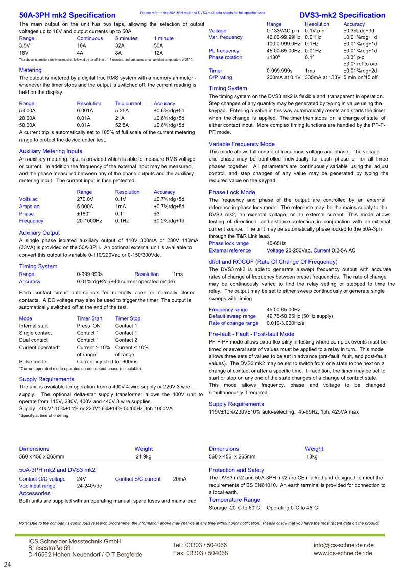
Please refer to the 50A-3PH mk2 and DVS3 mk2 data sheets for full specifications
Dimensions Weight 560 x 456 x 265mm 24.9kg
Dimensions Weight 560 x 456 x 265mm 13kg
50A-3PH mk2 Specification The main output on the unit has two taps, allowing the selection of output
voltages up to 18V and output currents up to 50A.
Range Continuous 5 minutes 1 minute
3.5V 16A 32A 50A
18V 4A 8A 12A The above intermittent on times must be followed by an off time of 15 minutes, and are based on an ambient temperature of 25°C.
Metering The output is metered by a digital true RMS system with a memory ammeter -
whenever the timer stops and the output is switched off, the current reading is
held on the display.
Range Resolution Trip current Accuracy
5.000A 0.001A 5.25A ±0.6%rdg+5d
20.00A 0.01A 21A ±0.6%rdg+5d
50.00A 0.01A 52.5A ±0.6%rdg+5d
A current trip is automatically set to 105% of full scale of the current metering
range to protect the device under test.
Auxiliary Metering Inputs An auxiliary metering input is provided which is able to measure RMS voltage
or current. In addition the frequency of the external input may be measured,
and the phase measured between any of the phase outputs and the auxiliary
metering input. The current input is fuse protected.
Range Resolution Accuracy
Volts ac 270.0V 0.1V ±0.7%rdg+5d
Amps ac 5.000A 1mA ±0.7%rdg+5d
Phase ±180° 0.1° ±3°
Frequency 20-1000Hz 0.1Hz ±0.2%rdg+1d
Auxiliary Output A single phase isolated auxiliary output of 110V 300mA or 230V 110mA
(33VA) is provided on the 50A-3PH. An optional external unit is available to
convert this output to variable 0-110/220Vac or 0-150/300Vdc.
Timing System Range 0-999.999s Resolution 1ms
Accuracy 0.01%rdg+2d (+4d current operated mode)
Each contact circuit auto-selects for normally open or normally closed
contacts. A DC voltage may also be used to trigger the timer. The output is
automatically switched off at the end of the test.
Mode Timer Start Timer Stop
Internal start Press ‘ON’ Contact 1
Single contact Contact 1 Contact 1
Dual contact Contact 1 Contact 2
Current operated* Current > 10% Current < 10%
of range of range
Pulse mode Current injected for 600ms *Current operated mode operates on one output phase (selectable).
Supply Requirements The unit is available for operation from a 400V 4 wire supply or 220V 3 wire
supply. The optional delta-star supply transformer allows the 400V unit to
operate from 115V, 230V, 400V and 440V 3 wire supplies.
Supply : 400V*-10%+14% or 220V*-6%+14% 50/60Hz 3ph 1000VA *Specify at time of ordering
DVS3-mk2 Specification Range Resolution Accuracy Voltage 0-133VAC p-n 0.1V p-n ±0.3%rdg+3d Var. frequency 40.00-99.99Hz 0.01Hz ±0.01%rdg+1d 100.0-999.9Hz 0.1Hz ±0.01%rdg+1d PL frequency 45.00-65.00Hz 0.01Hz ±0.01%rdg+1d Phase rotation ±180º 0.1º ±0.3º p-p ±3.0º ref to o/p Timer 0-999.999s 1ms ±0.01%rdg+2d O/P rating 200mA at 0.1V 335mA at 133V 5 min on/15 off
Timing System The timing system on the DVS3 mk2 is flexible and transparent in operation.
Step changes of any quantity may be generated by typing in value using the
keypad. Entering a value in this way automatically resets and starts the timer
when the change is applied. The timer then stops on a change of state of
either contact input. More complex timing functions are handled by the PF-F-
PF mode.
Variable Frequency Mode This mode allows full control of frequency, voltage and phase. The voltage
and phase may be controlled individually for each phase or for all three
phases together. All parameters are continuously variable using the adjust
control, and step changes of any value may be generated by typing the
required value on the keypad.
Phase Lock Mode The frequency and phase of the output are controlled by an external
reference in phase lock mode. The reference may be the mains supply to the
DVS3 mk2, an external voltage, or an external current. This mode allows
testing of directional and distance protection in conjunction with an external
current source. The unit may be automatically phase locked to the 50A-3ph
through the T&R Link lead.
Phase lock range 45-65Hz
External reference Voltage 20-250Vac, Current 0.2-5A AC
df/dt and ROCOF (Rate Of Change Of Frequency) The DVS3 mk2 is able to generate a swept frequency output with accurate
rates of change of frequency between preset frequencies. The rate of change
may be continuously varied to find the relay setting or stepped to time the
relay. The output may be set to either sweep continuously or generate single
sweeps with timing.
Frequency range 45.00-65.00Hz Default sweep range 49.75-50.25Hz (50Hz supply) Rate of change range 0.010-3.000Hz/s
Pre-fault - Fault - Post-fault Mode PF-F-PF mode allows extra flexibility in testing where complex events must be
timed or several sets of values must be applied to a relay in turn. This mode
allows three sets of values to be set in advance (pre-fault, fault, and post-fault
values). The DVS3 mk2 may be set to switch from one state to the next on a
change of contact or after a specific time. In addition, the timer may be set to
start or stop on any one of the state changes of a change of contact state.
This mode allows frequency, phase and voltage to be changed
simultaneously if required.
Supply Requirements 115V±10%/230V±10% auto-selecting. 45-65Hz, 1ph, 425VA max
Contact O/C voltage 24V Contact S/C current 20mA Vdc input range 24-240Vdc
Accessories Both units are supplied with an operating manual, spare fuses and mains lead
Protection and Safety The DVS3 mk2 and 50A-3PH mk2 are CE marked and designed to meet the
requirements of BS EN61010. An earth terminal is provided for connection to
a local earth.
Temperature Range Storage -20°C to 60°C Operating 0°C to 45°C
50A-3PH mk2 and DVS3 mk2
24
Note: Due to the company’s continuous research programme, the information above may change at any time without prior notification. Please check that you have the most recent data on the product.
ICS Schneider Messtechnik GmbHBriesestraße 59D-16562 Hohen Neuendorf / O T Bergfelde
Tel.: 03303 / 504066Fax: 03303 / 504068
info@ics-schneide r.dewww.ics-schneider.de

750ADM-H Features
Primary injection up to 750A
4V output*
16V 40A output for secondary injection
True RMS memory ammeter with single cycle capture
Multi-function timing system
Large back-lit liquid crystal display
Thermal and over-current protection
Automatic switch-off at end of test
Compact and portable
Automatic mains voltage selection*
T&R Test Equipment is a market leader in the field of current
injection equipment. The range includes secondary injection
units with 100A output capability up to 6000A primary
injection systems. All have true RMS metering, a flexible
timing system, and an easy to understand user interface.
The 750ADM-H mk2 is a compact, rugged primary current
injection system with a 750A output capability. The 750ADM-
H mk2 has a maximum no load output voltage of 5V. The
unit is ideally suited to all low power primary injection tasks
requiring up to 750A for short periods.
Where higher currents and powers are
required for primary injection, 11kVA
and 20kVA primary injection systems
are available. The PCU1-SP and
PCU2/E systems have separate control
and loading units, allowing a wide range
of load conditions to be covered with
different loading units.
The unit has two outputs, allowing injection of currents as low
as a few hundred milliamps and up to 750A. Voltages up to
16V are available on the 40A output, allowing higher
impedance trips to be tested. Four true RMS metering
ranges are provided, allowing the full scale of the meter and
trip level to be set independently of the selected output. The
metering has a capture time of less than 20ms, allowing the
rms of a single cycle to be accurately measured. Industry
standard connectors are used on all inputs and outputs for
convenience, reliability and safety.
The 750ADM-H mk2 is comprehensively protected by
electronic overcurrent and thermal trips.
The timing system is very flexible without compromising ease
of use, allowing trip times, reset times and reclose times to be
quickly measured to a high degree of accuracy. Two contact
inputs are provided, each of which may be trigged by a volt-
free contact or a dc voltage. The contact inputs auto-sense
for normally open or normally closed contacts.
The 750ADM-H mk2 can be used to test many devices
including:
Circuit breakers
Primary injection of over-current relays
Auto-reclosers
MCB’s
CT ratio (with external meter for secondary current)
Unit type Max. power Max. current
750ADM-H 3kVA 750A
PCU1-SP + NLU5000 11.5kVA 3kA 5min/5kA 40s
PCU2 mk5 + LU6000 20kVA 6kA
PCU1-SP and NLU5000
*See specifications overleaf
Current Injection Systems
25
mk2

Main Output The main output on the unit has two taps, allowing the selection
of output voltages up to 16V and output currents up to 750A.
The unit operates at slightly reduced ratings when operating from
a 115V supply.
115V 230V
Open circuit voltage 3.5V 5.0V
Voltage at 500A 2.8V 4V
Continuous current 125A 125A
5 min on 250A 250A
1 min on 440A 500A
Max current 500A 750A
Max current on time 10s 20s
Open circuit voltage 10V 16V
Full load voltage 7.5V 10V
Continuous current 10A 10A
1 min on 40A 40A
Metering The output is metered by a digital true RMS system with a
memory ammeter - whenever the output is switched off, the
current reading is held on the display.
Range Resolution Trip current Accuracy Capture time
20.00A 0.01A 21A ±0.5%rdg+5d 20ms
50.00A 0.01A 53A ±0.5%rdg+5d 20ms
200.0A 0.1A 210A ±0.5%rdg+5d 20ms
750A 1A 788A ±0.5%rdg+2d 20ms
A current trip is automatically set to 105% of full scale of the
selected metering range to protect the device under test.
Timing System Range 0-999.999s/9999.99s/99999.9s auto-ranging
Resolution 1ms/10ms/100ms
Accuracy ±0.01%rdg+2d (all modes except current operated) ±0.01%rdg+4d (current operated mode)
The contact circuits have an open circuit voltage of 24VDC and a
short circuit current of 20mA. Each contact circuit will auto-
select for normally open or normally closed contacts. A DC
voltage of 24-240VDC may also be used to trigger either timer
channel.
The following functions are provided:
Mode Timer Start Timer Stop
Off Timer inactive Timer inactive
Internal start Press ‘ON’ Contact 1
Single contact Contact 1 Contact 1
Dual contact Contact 1 Contact 2
Current operated Current > 20% Current < 20%
of range of range
The output is automatically switched off at the end of the test to
safeguard the relay under test.
RS232 An RS232 port is provided to allow connection to a PC or a
printer.
T&R Link The T&R Link allows a T&R DVS3 mk2 voltage source to phase
lock to the 750ADM–H current.
Supply Requirements Auto-selecting 115V±10% 50/60Hz 1ph 1900VA max
230V±10% 50/60Hz 1ph 3900VA max
Temperature Range Storage -20°C to 60°C Operating 0°C to 45°C
Dimensions Weight 560 x 456 x 265mm 27.4kg
Accessories Operating manual, mains lead, and carrying strap.
Optional 750ADM-AL Lead Set specifications A range of output leads are available to complement the
750ADM-H. The standard 750ADM-AL lead set is 3m long,
recommended for use with a 230V Supply. A 1.5m lead set is
also available, and is recommended when operating from a 115V
supply. The leads consist of double insulated 95mm2 welding
cable terminated in Dinse high current connectors at the
750ADM end and high current welding clamps at the load end.
Low current timer
leads are also included
with the lead set:
The 3m lead set weighs
9.8kg including high
current leads and timer
leads.
Protection and Safety The unit is protected by electronic over current and thermal trips
on the outputs, and circuit breakers on the input and power
circuit. An earth terminal is provided for connection to a local
earth when testing in a substation environment. The unit is
designed to comply with BSEN61010, and is CE marked.
750ADM-H mk2 Specification
750A
Out
put
40A
Out
put
26
Note: Due to the company’s continuous research programme, the information above may change at any time without prior notification. Please check that you have the most recent data on the product.
ICS Schneider Messtechnik GmbHBriesestraße 59D-16562 Hohen Neuendorf / O T Bergfelde
Tel.: 03303 / 504066Fax: 03303 / 504068
info@ics-schneide r.dewww.ics-schneider.de

The control units are rated at 11.5kVA with a 2 second
overload capability of 23kVA using pulse mode. All metering
is digital and a memory facility is provided to hold the current
reading when the output trips or is switched off. The PCU1
systems have a high accuracy timing system with 1ms
resolution. Selection for normally open or normally closed
contacts is automatic, and the status of the contacts is shown
on the front panel. Timing modes are available for under and
over current devices, re-closers, under and over voltage
devices, current trips and circuit breakers.
The PCU1 series are medium powered primary current
injection systems offering output currents up to 5000A. The
system consists of a separate control unit containing all
metering and control functions and a loading unit that
provides the high current output. The PCU1-SP mk2 is
ideally suited to primary current injection, stability testing and
circuit breaker testing. In addition, it offers direct-reading CT
ratio and polarity tests and a 100A secondary injection
output. T&R also offer the higher-powered PCU2 system.
Features
5kA maximum output current (higher overload currents for 2s)
Multi-function digital timing system
True RMS memory ammeter with single cycle capture
2000A and 5000A loading units
Three range outputs on loading units
Rugged, compact design
Optional trolley mounting of system
Secondary injection up to 100A
Direct reading CT ratio and polarity
Feature PCU1-SP mk2 PCU2
Primary injection
Max output power 11.5kVA
40s
20kVA
5 min
Secondary injection
CT ratio/polarity test
Two loading units are available, delivering a maximum output
current of 2000A or 5000A. Each loading unit has three
output taps to allow for a wide range of load impedances.
For example, the NLU5000 may be configured to either give
a maximum current of 5000A on the 2.3V range, 2500A on
the 4.6V range or 1250A on the 9.2V range.
PCU1-SP mk2
Primary Current Injection System
PCU1-SP & NLU5000 with
optional trolley
27

PCU1-SP mk2 Specification Loading Unit Current Metering The AC output current is metered by a true RMS memory
ammeter (acquisition time 200ms) with a liquid crystal display.
The current metering has 3 ranges corresponding to 10%, 50%
and 100% of the maximum rating of the loading unit. In addition,
a 200% metering range is enabled in pulse mode.
NLU2000
Range Full scale Resolution Accuracy
10% 200.0A 0.1A ±0.5%rdg+5d 50% 1000A 1A ±0.5%rdg+5d 100% 2000A 1A ±0.5%rdg+5d 200% 4000A 1A ±1%rdg+5d
NLU5000
Range Full scale Resolution Accuracy
10% 500.0A 0.1A ±0.5%rdg+5d* 50% 2500A 1A ±0.5%rdg+5d* 100% 5000A 1A ±0.5%rdg+5d* 200% 10kA 10A ±1.5%rdg+5d * ±1.5%rdg+5d pulse mode
Timing System The PCU1 systems have a flexible timing system with two
contact inputs and 5 operating modes. Each contact circuit
automatically selects for N/O or N/C contacts, and the status of
each contact input is shown by an LED. The timing channels
may also be triggered by a dc voltage between 24 and 240V.
Timer resolution 1ms
Timer full scale 999.999s
Timer accuracy ±0.01%rdg+2d (4d current mode)
Contact O/C voltage 24V
Contact S/C current 20mA
Vdc input range 24-240Vdc
Timer mode Timer start Timer stop
Internal Start ‘On’ button Contact
Single contact Contact 1 Contact 1
Dual contact Contact 1 Contact 2
Current operated ** Current >20% rng Current <20% rng Pulse mode 0.2s * ‘On button’ 0.2s
Pulse mode 0.5s * ‘On button’ 0.5s
Pulse mode 1s * ‘On button’ 1s
Pulse mode 2s * ‘On button’ 2s
Off Setting position
*Pulse mode applies current to the load for a maximum of the
specified time. If contact set 1 changes state or the current
drops below 20% of the metering range during the pulse time,
the timer is stopped. The maximum output current is increased
in pulse mode. The maximum obtainable current is set by the
impedance of the test object and output leads.
**Current operated mode is used to time circuit breakers with no
auxiliary contacts. The timer is started when the current exceeds
20% of the selected metering range (e.g. 100A on the NLU5000
500A range). The timer stops when the current falls.
Secondary Injection Output Output Range Continuous Intermittent current current 5min on* 1 min on* 0-5V 33A 67A 100A 0-16V 10A 20A 30A *All on times must be followed by an off time of 15 minutes
Metering Range Resolution Accuracy Current trip
10.00A 0.01A ±0.5%rdg+5d 10.5A
20.00A 0.01A ±0.5%rdg+5d 21A
100.0A 0.1A ±0.5%rdg+5d 100A
Supply Requirements 230V±10%, 45-65Hz 1ph 11.5kVA max (23kVA overload for 2s)
Control Unit Standard Accessories Mains lead (5m), loading unit power and metering leads (5m),
operating manual and spare fuses.
Dimensions Weight PCU1-SP 450(w) x 275(h) x 305mm(d) 26kg
NLU2000 450(w) x 275(h) x 370mm(d) 49kg
NLU5000 450(w) x 275(h) x 370mm(d) 58kg
Temperature Range Storage -20°C to 60°C, Operating 0°C to 45°C
Protection and Safety The PCU1 series and loading units are CE marked and are
designed to meet the requirements of BS EN61010. The system
is protected by electronic trips on the outputs, circuit breakers on
the mains input, and control unit output. The unit also has a duty
cycle trip on the loading unit output and thermal protection.
Optional Loading Unit Specifications Two loading units are available to provide a range of output
currents suitable for different primary injection tasks. Each
loading unit has three output taps allowing current injection into a
wide range of loads of differing impedances.
NLU5000 Loading Unit Intermittent Ratings Output Maximum current Voltage* Cont. 5 min 1 min 40s 2.3V 1500A 3000A 4500A 5000A 4.6V 750A 1500A 2250A 2500A 9.2V 375A 750A 1125A 1250A
NLU2000 Loading Unit Intermittent Ratings Output Maximum current Voltage* Cont. 5 min 1 min 40s 4V 600A 1200A 1800A 2000A 8V 300A 600A 900A 1000A 16V 150A 300A 450A 500A *open circuit voltage at 230V mains
Optional Output Lead Set Specifications Type Length CSA Termination
1000NAL 1m to 5m 140mm2 Copper bar
2000NAL 1m to 5m 280mm2 Copper bar
3000NAL** 1m to 3hm 420mm2 Copper bar
5000NAL** 1m to 3m 560mm2 Copper bar *Output currents above 3000A require very short leads, and longer leads will
restrict the maximum current available
I<20
% ra
nge
Con
tact
1
28
Note: Due to the company’s continuous research programme, the information above may change at any time without prior notification. Please check that you have the most recent data on the product.
ICS Schneider Messtechnik GmbHBriesestraße 59D-16562 Hohen Neuendorf / O T Bergfelde
Tel.: 03303 / 504066Fax: 03303 / 504068
info@ics-schneide r.dewww.ics-schneider.de

Primary Current Injection System
Features
20kVA 5 minute output capability
Continuously variable output
Multi-function timing system
Digital true RMS memory ammeter
Bright LED displays
Automatic switch-off at end of test
Centralised control and metering
Separate control and loading units
Output up to 10kA
Low impedance, dual-range outputs
The PCU2 Mk5 primary current injection system is ideally
suited to commissioning and maintenance testing where very
high currents are required. The system consists of separate
control and loading units for maximum flexibility. The control
unit contains all control and metering circuitry, and is linked to
the loading unit by control and metering cables.
The control unit may be used with one of two loading units
providing between 5000A or 6000A for 5 minutes or up to 10
or 12kA for short periods. Each loading unit has two outputs
which may be connected in series or parallel for maximum
flexibility. For example, the LU6000 may be configured to
either give a maximum current of 3000A at 6.6V or 6000A at
3.3V.
The control and loading units are each housed in tough steel
cases fitted with castors and protective lifting handles. The
loading units have a small plan area to allow them to be
positioned as close as possible to the test object, minimising
power requirements and maximising the available current.
The PCU2 Mk5 control unit is shown here with an LU5000
loading unit. This combination may be used to inject currents
of up to 5000A for 5 minutes, 8000A for 5 seconds or 10000A
for 1 second.
This unit is ideally suited to all primary current injection tasks,
including testing under and over current relays, circuit
breakers and CT ratio testing.
PCU2 mk5
The control unit is rated at 20kVA and has digital metering. A
memory facility is provided on the metering to hold the
current reading when the output trips or is switched off. The
current is automatically switched off when the device under
test trips.
A flexible timing system is provided, allowing timing tests to
be carried out to a resolution of 1ms. Selection for normally
open or normally closed contacts is automatic, and the status
of the contacts is shown on the front panel. Timing modes
are available to test under and overcurrent devices,
reclosers, under and over voltage devices, current trips and
circuit breakers.
29

PCU2 mk5 System Specification Metering The AC output current is metered by a true RMS 4 digit memory
ammeter with an LED display.
Timing System The PCU2 mk5 has a flexible timing system with two contact
inputs and 5 operating modes. Both the start and stop contact
circuits will accept volt free contacts. Each contact circuit
automatically selects for N/O or N/C contacts, and the status of
each contact input is shown by an LED. In addition to contact
operation, the first timing channel may be triggered by a dc
voltage between 24 and 240V. The timing system will also
respond to the rise and fall of current in the test object for
devices where no auxiliary contact is available. A pulse mode is
also provided to allow injection for short periods (500ms) to avoid
unnecessarily heating thermal trips.
Timer resolution 1ms
Timer full scale 999.999s
Timer accuracy ±0.01%rdg+2d
±0.01%rdg+3d current operated mode Contact O/C voltage 24V
Contact S/C current 100mA
Vdc input range 24-240Vdc
Timer mode Timer start Timer stop
Normal ‘On’ button Contact
Single contact Contact 1 Contact 1
Dual contact Contact 1 Contact 2
Current Current >20% Current <20%
of range of range
Off Timer inactive
Accessories supplied with system Spare fuse set, operating manual.
1 x 5m loading unit power interconnection lead.
1 x 5m loading unit metering interconnection lead.
1 x 2m mains lead
Unit Dimensions Weight Control unit 660 x 400 x 740mm 115kg
LU5000 660 x 400 x 740mm 155kg
LU6000 660 x 400 x 740mm 135kg
Optional Output Lead Set Specifications A range of output lead sets are available to complement the
PCU2 mk5 system with current ratings between 3000A and
6000A. The leads are double insulated and have good flexibility.
Type Length CSA Termination
3000AL 2.5m 560mm2 Copper bar
4000AL 2.5m 700mm2 Copper bar
5000AL 2m 840mm2 Copper bar
6000AL 2m 1120mm2 Copper bar
Other output
lead lengths
are available
on request.
30
Parallel mode Series mode
Range 1 Full scale 5000A 2500A
Resolution 1A 1A
Accuracy 0.6% rdg+6d 0.6% rdg+6d
Current trip 5500A 2750A
Full scale 10.00kA 5.00kA Range 2
Resolution 0.01kA 0.01kA
Accuracy 0.6% rdg+6d 0.6% rdg+6d
Current trip 11000A 5500A
Memory ammeter aquisition time 200ms
Loading Unit Output The output of the loading unit is continuously variable from zero.
Each unit may be operated in series/parallel mode to allow for a
greater range of load impedances. All metering and tripping
functions are handled by the control unit.
Protection and Safety The PCU2 mk5 and loading units are CE marked and are
designed to meet the requirements of BS EN61010.
The system is protected by a circuit breaker and fuse on the
mains input, a circuit breaker on the loading unit output and an
electronic trip on the output.
Supply Requirements 230V±10% 49-61Hz 1ph 23kVA 5 min/46kVA 1s
Temperature Range Storage -20°C to 60°C, Operating 0°C to 45°C
LU5000 LU6000
Parallel
mode
Series
mode
Parallel
mode
Series
mode
Open circuit V 0-4V 0-8V 0-3.3V 0-6.6V
Current 2500A 1250A 3000A 1500A
Max kVA 10 10 10 10
Current 5000A 2500A 6000A 3000A
Max kVA 20 20 20 20
Current 8000A 4000A 9600A 4800A
Max kVA 32 32 32 32
Current 10000A 5000A 12000A 6000A
Max kVA 40 40 40 40
Con
tinu-
ous
5 m
in o
n/
15 m
in o
ff 5
sec
on
1 se
c on
Lead termination
Note: Due to the company’s continuous research programme, the information above may change at any time without prior notification. Please check that you have the most recent data on the product.
ICS Schneider Messtechnik GmbHBriesestraße 59D-16562 Hohen Neuendorf / O T Bergfelde
Tel.: 03303 / 504066Fax: 03303 / 504068
info@ics-schneide r.dewww.ics-schneider.de

The unit has data logging facilities using a standard USB
memory key. Date, time, current, voltage, phase angle, and
frequency are stored to a CSV file on the memory key along
with a comment entered using the supplied USB keyboard.
Pressing the “store” pushbutton causes a new set of values
to be written to the CSV file.
The output has three taps (75V, 150V & 300V), allowing the
measurement of impedance of a wide range of lines and
cables. All metering is true rms. Four current ranges (2.000,
The PCU1-C is a cable impedance test system for the
measurement of impedance of overhead lines and
underground cables. The system consists of a separate
control unit containing all metering and control functions and
an output transformer that provides isolation of the output
current and feedback voltage.
A current is injected into the line under test and the resultant
magnitude and phase angle of the voltage across the line is
measured. The current, voltage, phase angle and impedance
of the line (Z & X) under test are displayed. In addition, the
harmonic content of the voltage and current can be
displayed.
Features
Measure impedance of overhead lines and underground cables
Direct readout of cable Z & X
Phase angle display
Voltage up to 300V and current up to 80A
Data storage to CSV file on USB memory key
Multi-function digital timing system
Digital true RMS memory ammeter & voltmeter
Solid state switching
Rugged, compact design
PCU1-C
10.00A 90.0° 1.000V Z=100.0m© X=100.0m©
10.00, 20.00 and 100.0A) and two voltage ranges (30.00V
and 300.0V) are provided.
The output transformer unit uses 6mm safety connectors for
all outputs and 4mm safety connectors for inputs. A block of
connectors is provided adjacent to the output to allow easy
parallel connection of cables for parallel measurements on all
three phases.
The unit is provided with a set of four 10m 12mm2 duplex
measurement cables. These provide a 12mm 2 conductor for
current injection and a 6mm 2 conductor for voltage feedback
in each cable.
Cable Impedance Test System
31

PCU1-C Specification The AC output current and load voltage are measured by a true
RMS metering system with hold facility. All readings are held
when the output is switched off. Four current ranges and two
voltage metering ranges are provided.
Range Full scale Resolution Accuracy
2A 2.000A 0.001A ±1%rdg+5d 10A 10.00A 0.01A ±1%rdg+5d 20A 20.00A 0.01A ±1%rdg+5d 100A 100.0A 0.1A ±1%rdg+5d
30V 30.00V 0.01V ±1%rdg+5d 300V 300.0V 0.1V ±1%rdg+5d
Phase 0-±180.0° 0.1° ±1°
Output ratings Current rating
Output Continuous 5 min on Maximum
75V 80A 40A 80A 80A 150V 40A 20A 40A 40A 300V 20A 10A 20A 20A
Data Storage All test results from the PCU1-C can be stored on a USB
memory key. The unit has a real-time clock to time and date-
stamp all results. To log results first enter a comment for the
results using the USB keyboard, and then select ’auto store’.
Whenever the ‘store’ key is pressed the current, voltage and all
other parameters are added to a spreadsheet file on the memory
key. The current set of results can be viewed on the display. All
results are stored in a folder on the USB key named with the test
date in a file named with the time. In addition, the PCU1-C can
store the voltage and current waveforms to the USB key in CSV
format.
Dimensions Weight PCU1-C 450(w) x 275(h) x 305mm(d) 26kg
NLU75/80 450(w) x 275(h) x 330mm(d) 50kg
Temperature Range Storage -20°C to 60°C, Operating 0°C to 45°C
Protection and Safety Isolation is provided on all outputs and inputs to be connected to
the line under test.
The PCU1-C system is CE marked and is designed to meet the
requirements of BS EN61010. The system is protected by
electronic trips on the outputs, circuit breakers on the mains
input and output. The unit also has a duty cycle trip on the
loading unit output and comprehensive thermal protection.
Supply Requirements 230V±10%, 45-65Hz 1ph 7kVA max
Standard Accessories Mains lead (5m).
Power and metering interconnection leads (5m).
Earth lead.
3 x 10m overhead line Kelvin connection leads.
1 x 10m earth Kelvin connection lead.
Link lead to connect output to parallel connection block.
USB keyboard, USB memory key.
Operating manual.
Sample data stored to USB key "PCU1-C ","V0.12","C00","P1","A1"
"Time","Date","Amps","Volts","Phase","Freq Hz","Z","X","Comment"
"11:18:40","21/12/09","10.00","1.000","90.0","0.1000","0.1000","Cable Sub xx to yy phase A-B"
"11:19:42","21/12/09","10.00","1.000","90.0","0.1000","0.1000","Cable Sub xx to yy phase B-C"
"11:20:49","21/12/09","10.00","1.000","90.0","0.1000","0.1000","Cable Sub xx to yy phase C-A"
"11:20:49","21/12/09","10.00","1.000","90.0","0.1000","0.1000","Cable Sub xx to yy ABC-E"
AABC
Overhead line Kelvin
connection clamp
Phase A to phase B impedance test
32
Note: Due to the company’s continuous research programme, the information above may change at any time without prior notification. Please check that you have the most recent data on the product.
ICS Schneider Messtechnik GmbHBriesestraße 59D-16562 Hohen Neuendorf / O T Bergfelde
Tel.: 03303 / 504066Fax: 03303 / 504068
info@ics-schneide r.dewww.ics-schneider.de

DMO200
33
Digital Micro-Ohmmeter
mV Input Sense input for 4 wire resistance
measurement.
Colour LCD
Simultaneous
display of
current, sense
voltage and
resistance.
USB data storage
All test results
can be stored
automatically on
a standard USB
memory key. The
unit has a real-
time clock to time
and date-stamp all
results. Results are
written to a CSV file
that can be opened
by any spreadsheet
program. A USB
keyboard is supplied to
add comments to
results.
Universal supply 90-264V supply voltage with no
restriction on output current.
Comment Press this button to enter a new
comment on the keyboard.
Main Output 5V 1-200A pre-settable current.
Thermal and over-current
protection. <2.5% ripple.
Test current presets Programmable buttons to set test
currents. Set to 50A, 100A and
200A by default.
A USB keyboard and USB memory key
are supplied with the DMO200.
Standard lead set High quality 3m 200A output leads
in carry case supplied with unit.
Current clamp input Connect the optional DC
current clamp to measure
resistances with both sides
Optional extension lead sets Optional output and sense extension lead sets
available in 3m, 5m and 10m lengths.
Optional Kelvin clamp lead set Optional 200A Kelvin lead set-current injected
and sense voltage measured using one clamp.

34
Example Applications Busbar joint resistance The DMO200 is ideal for measuring busbar joint resistance.
Before making connections ensure that the supply is off and
necessary earths have been applied. Connect the high current leads
to the busbar, ensuring that the joint resistance to be measured is
in the circuit. Connect the sense leads as close as possible to the
joint to be measured. Select the desired test current using one of
the preset test currents (or use the adjust knob to set a custom test
current). Switch the output on, and the current rises to the preset
current. Switch the output off again, and the reading is held on the
display.
Circuit breaker contact resistance The DMO200 is suited to all low resistance measurements on power
systems, and is particularly suited to measuring contact resistances
on substation circuit breakers, isolators and grounding equipment.
The unit has a powerful output capable of driving 200A through 20m
output leads to reach the contacts of even the largest circuit
breakers. Optional output lead extensions are available which
extend the high current and sense leads by 3, 5 or 10m.
Accurate measurements on circuit breakers, isolators and grounding
links with both sides earthed are simple with the optional current
clamp. This allows the current flowing through the earthing
equipment to be subtracted from the test current.
Bu
sba
r B
usb
ar
Storing results The DMO200 is supplied with a USB memory key and USB keyboard
for storing annotated results. To enter or edit a comment tap the
COMMENT/MENU button. The comment can then be edited using
the keyboard. This comment is stored with each result until a new
comment is entered. Each time the output of the unit is switched off
the readings from the unit are saved to the USB memory key in CSV
format along with the date, time and your comment.
The CSV file can be opened with any spreadsheet program such as
Microsoft Excel™ or similar.
Details Supply requirements: 90-265Vac 1300VA max
Output: 1-200Adc 5V
Resistance measurement: 0.1-5
DMO200 dimensions: 360 x 290 x 165mm
DMO200 weight: 6.9kg Accessories supplied with unit: Mains lead, user manual,
3m high current leads, 3m sense leads, spare fuses.
Optional accessories
DMO200 current clamp Part no. A224-0001
3m Kelvin clamp lead set in plastic case Part no. A224-0003
Output/sense extension 3m in plastic case Part no. A224-0004
Output/sense extension 5m in plastic case Part no. A224-0005
Output/sense extension 10m in plastic case Part no. A224-0006
Note: Due to the company’s continuous research programme, the information above may change at any time without prior notification. Please check that you have the most recent data on the product.
ICS Schneider Messtechnik GmbHBriesestraße 59D-16562 Hohen Neuendorf / O T Bergfelde
Tel.: 03303 / 504066Fax: 03303 / 504068
info@ics-schneide r.dewww.ics-schneider.de

DMO600 Digital Micro-Ohmmeter with USB data storage
T&R Test Equipment is a market leader in the field of power
test equipment.
The DMO600 is a 600A micro-ohm meter. It is simple to
operate, and automatically maintains desired output current.
Output current, voltage and resistance are all displayed
simultaneously. The DMO600 uses a four wire Kelvin
connection to measure low resistance. The resistance is
calculated from the test current and sense voltage.
The unit can output any current from 10A to 600A, and has the
option of three pre-programmable test currents, which can be
selected at any time. The unit is designed to comply with
BSEN61010, and is CE marked.
Storing results The DMO600 is supplied with a USB memory key and USB
keyboard for storing annotated results. To enter or edit a
comment tap the COMMENT/MENU button. The comment can
then be edited using the keyboard. This comment is stored with
each result until a new comment is entered. Each time the output
of the unit is switched off the readings from the unit are saved to
the USB memory key in CSV format along with the date, time
and your comment.
The CSV file can be opened with any spreadsheet program such
as Microsoft Excel™ or similar application.
Test Limits The DMO600 comes with the option of applying upper and
lower pass limits for resistance and length of test for
production line applications.
There is the option for up to three limit test setups each with
their own resistance limits, and test current times. When the
current has been set and the pre-set time has elapsed a pass
or fail indication is shown.
Features
Clear and simple user interface
10-600A DC Test Current
0.1µΩ—5Ω Resistance
USB Test Data storage
600A for 2 minutes with 15 minutes off
200A continuous current
Colour LCD display
Programmable test current
90-264V supply voltage
Thermal and over-current protection
Portable is sturdy case
Output ripple is <2.5%
High quality 3m lead set supplied as standard.
35
Three Pre-programmable test currents.
Option to enter a
comment using
USB keyboard.
Simultaneous
display of current,
mV and resistance.
Clear output status
for user safety

Busbar join resistance The DMO600 is ideal for measuring busbar joint resistance.
Before making connections ensure that the supply is off and
necessary earths have been applied. Connect the high current
leads to the busbar, ensuring that the joint resistance to be
measured is in the circuit. Connect the sense leads as close as
possible to the joint to be measured. Select the desired test
current using one of the preset test currents (or use the adjust
knob to set a custom test current). Switch the output ON, and the
current rises to the preset current. Switch the output OFF again,
and the reading is held on the display.
Circuit breaker contact resistance The DMO600 is suited to all low resistance measurements on
power systems, and is
particularly suited to
measuring contact
resistances on
substation circuit
breakers, isolators
and grounding
equipment. The unit
has a powerful output
capable of driving
600A through 20m
output leads to reach
the contacts of even
the largest circuit
breakers. Optional
output lead extensions
are available which
extend the high
current and sense
leads by 3, 5 or 10m.
Accurate
measurements on
circuit breakers,
isolators and grounding links with both sides earthed are simple
with the optional current clamp. This allows the current flowing
through the earthing equipment to be subtracted from the test
current.
Main Output The main output allows for output currents up to 600A.
Range Continuous 2 minutes
5Vdc 200A 600A
The above intermittent on times must be followed by an off time
of 15 minutes, and are based on an ambient temperature of 25°C.
Metering The output is metered by a digital true RMS system. Whenever
the output is turned off, the current reading is held on the display.
Range Resolution Accuracy
10.0-600.0A 0.1A ±0.5%rdg±1d
A current trip is automatically detected.
Sense Voltage Inputs Maximum measurement voltage is 5V dc
Range Resolution Accuracy
0-9.999mV 0.001mV ±0.5%rdg±5d
10.00-99.99mV 0.01mV ±0.5%rdg±5d
100.0-999.9mV 0.1mV ±0.5%rdg±5d
1.000-5.000V 0.001V ±0.5%rdg±5d
Resistance accuracy The calculated resistance accuracy is:
Range Resistance Accuracy
100-600A Full Scale ±1%rdg±2d
10-99A Full Scale ±1.5%rdg±10d
Lead Set Specifications
2 x 3m 95mm2 output leads terminated in large current clamps.
1 x 3m voltage sense leads, 1 x 5m Earth lead, 1 x 5m Mains
lead.
Supply Requirements The unit is available for operation from:
90-264Vac -10%+14% 50/60Hz 1ph 3800VA
RS232 An RS232 port is provided to allow connection of a printer or PC.
A PC connection allows for remote control of the output current,
and recording of test results.
Temperature Range Storage -20°C to 60°C Operating 0°C to 45°C
Accessories Operating manual, output lead set, mains lead, earth lead, USB
memory key, USB keyboard.
Optional Accessories DMO600 current clamp Part no. A224-0001 Output/sense extension 3m in plastic case Part no. A231-0004 Output/sense extension 5m in plastic case Part no. A231-0005 Output/sense extension 10m in plastic case Part no. A231-0006 Dimensions Weight 560 x 456 x 265mm 19.7kg
DMO600 Specification
36
Example Applications
Note: Due to the company’s continuous research programme, the information above may change at any time without prior notification. Please check that you have the most recent data on the product.
ICS Schneider Messtechnik GmbHBriesestraße 59D-16562 Hohen Neuendorf / O T Bergfelde
Tel.: 03303 / 504066Fax: 03303 / 504068
info@ics-schneide r.dewww.ics-schneider.de

High Voltage DC Cable Test Systems
T&R Test Equipment is a market leader in the field of
protection test equipment. The range includes primary and
secondary current injection equipment up 6000A, voltage
sources, micro-ohmmeters and high voltage test systems up
to 100kV.
The PT18-10 and PT30-10 high voltage dc test sets are
designed to perform tests on installed cable and jointing
systems. The units have a variable output voltage with a
maximum or ±18kVdc (PT18-10) or ±30kVdc (PT30-10).
Both units have a maximum charging capability of 10mA. A
zero-volt interlock is fitted that prevents the output being
switched on unless the output control is at zero.
The units include an automatic load discharge system that
discharges the cable under test when the output is switched
off or a breakdown occurs. The internal dumping system can
discharge a maximum of 2.5kJ on each output,
corresponding to 10F at 18kV or 4 F at 30kV. In the event
of a test object failure, the overload circuit will automatically
switch off the output voltage and earth the output via the
internal discharge circuit. A manual discharge probe is also
supplied as standard with both units, allowing higher load
capacitances to be safely discharged.
The mk2 units introduce automatic 115/230V mains voltage
selection, allowing easy transition between site voltages.
The output voltage is metered by two large, linear, analogue
instruments marked 0-20kV (PT18-10) or 0-30kV (PT30-10).
Test object current is metered by two further analogue
instruments with 0-10 scale marking. The meters read 0-
10mA directly, or 0-1mA when the 10 push button is
operated. The HV output from both units use a high quality
plug and socket system, allowing for easy cable replacement.
The PT18-10 and PT30-10 are part of a comprehensive
range of AC & DC high voltage systems available
from T&R Test Equipment. The line-up
includes cable test sets from ±18kV to
±30kV dc and pressure test systems
up to 100kVac.
PT18-10
PT30-10
PT30-10
Features
±18kVdc output voltage (PT18-10) ±30kVdc output voltage (PT30-10)
10mA output capability
Both voltage and current metered on HV outputs
Automatic earth system for dumping capacitive loads
HV output plug & socket system
Key operated supply switch to prevent unauthorised operation
Automatic mains voltage selection
Visual indication of test piece failure
Zero Volt interlock
PT18-10
mk2
mk2
37

Output All of the PT series cable test systems have high quality high
voltage output connectors, and are supplied with detachable,
partially screened output cables
Unit type Voltage Continuous 5 minutes
PT18-10 0 to ±18kV 5mA 10mA
PT30-10 0 to ±30kV 5mA 10mA
The above intermittent on times must be followed by an off time
of 15 minutes, and is based on an ambient temperature of 25°C.
Metering The positive and negative output voltages on the PT series are
metered on the HV output by separate analogue instruments.
Unit Range Accuracy
PT18-10 0-20kV ±1.5% of full scale
PT30-10 0-30kV ±1.5% of full scale
The output current on both of the outputs is metered by a dual
range analogue instrument. The 1mA range is selected by the 10 pushbutton adjacent to the mA meter.
Unit Range Accuracy
PT18-10 10mA ±2.5% of full scale
1mA ±2.5% of full scale
PT30-10 10mA ±2.5% of full scale
1mA ±2.5% of full scale
Overload Protection The PT18-10 and PT30-10 are protected by an overload trip on
the output that operates at 12mA.
Load Discharge System The PT18-10 and PT30-10 are fitted with an automatic internal
load discharge system that grounds the load via a 20k resistor
on each output when the output is switched off. The discharge
system is rated to dissipate 2.5kJ once every 15 minutes on
each output. The PT18-10 can discharge a maximum load
capacitance of 10F per output from 18kV, and the PT30-10 can
discharge a maximum load capacitance of 4 F per output from
30kV.
Unit PT18-10 PT30-10
PT18-10 mk2 & PT30-10 mk2 Specification
DP20 Discharge probe
Maximum discharge energy 2.5kJ 2.5kJ
Maximum discharge capacitance 10F 4F
from unit max output voltage
The PT series units are supplied with a DP20 or DP40 manual
discharge probe to allow the discharge of higher capacitance
loads.
PT18-10 PT30-10
Discharge probe supplied DP20 DP40
Discharge probe max discharge voltage 20kV 40kV
Resistance 30k 60k
Maximum discharge energy 3.6kJ 7.2kJ
Maximum discharge capacitance 15F 11F
from DP max rated voltage
Supply Requirements
PT18-10 mk2 115V/230V±10% auto-selecting
50/60Hz 1ph 600VA max
PT30-10 mk2 115V/230V±10% auto-selecting
50/60Hz 1ph 750VA max
Protection and Safety The output of the unit is protected by an overload trip, and the
input and control supplies are protected by fuses.
The PT18-10 and PT30-10 are designed to meet the
requirements of BS EN61010.
An earth terminal is provided on the units which must be
connected to a low impedance local earth (lead not supplied as
standard).
Temperature Range Storage -20°C to 60°C Operating 0°C to 45°C
Dimensions Weight PT18-10 471x144x362mm 17kg unit only
25kg including bag & leads
PT30-10 471x191x362mm 25kg unit only
32kg including bag & leads
Standard Accessories Both units: Supply lead, spare fuse, operating manual,
5m HV output leads, 5m output earth lead.
PT18-10 DP20 discharge probe, carry case, lead bag.
PT30-10 DP40 discharge probe, carry case including space
for leads
Optional Accessories PT18-10 part no. PT30-10 part no.
10m HV leads A063-193 A064-111
10m earth lead A064-112 A064-112
15m HV leads A063-172 A064-100
15m earth lead A064-101 A064-101
20m HV leads A064-156 A064-156
20m earth lead A064-157 A064-157
38
Note: Due to the company’s continuous research programme, the information above may change at any time without prior notification. Please check that you have the most recent data on the product.
ICS Schneider Messtechnik GmbHBriesestraße 59D-16562 Hohen Neuendorf / O T Bergfelde
Tel.: 03303 / 504066Fax: 03303 / 504068
info@ics-schneide r.dewww.ics-schneider.de

Features
Continuously variable output voltage 0-5kVAC
Variable trip circuit 2-12mA and 20-120mA
Output voltage and current metering
Visual and audible indication of test piece failure
Compact lightweight instrument
Burn feature giving 100mA maximum current on short circuit
Key operated switch preventing unauthorised operation
Complies with the testing requirements of BS1363
indicated. The alarm must be manually reset after a trip
condition before testing can be resumed.
The instrument is supplied in a compact and portable case
with permanently connected test leads. The test leads are
terminated in clips. The unit is designed for operation in
conjunction with a suitable interlocked test enclosure or high
voltage test area.
The KV5-100 mk2
is one of a range of
high voltage test
systems available
from T&R Test
Equipment.
KV5-100 mk2
T&R Test Equipment is a market leader in the field of
protection test equipment. The range includes primary and
secondary current injection equipment up 6000A, voltage
sources, micro-ohmmeters and high voltage test systems up
to 100kV.
The KV5-100 mk2 high voltage test set is a general purpose
test instrument designed for testing insulation systems and
the measurement of breakdown voltage on electrical plant
and components.
The unit has an output voltage adjustable from zero to 5kV
with accurate metering on both the output voltage and
current. A zero-voltage interlock is provided, ensuring that
the output may only be energised with the voltage control at
zero.
The output voltage is metered by a large, linear analogue
instrument with a dual-scale marking of 0-3kV and 0-6kV.
Load current is metered by a second analogue instrument
with 0-10 scale marking. Two current ranges are selectable:
0-10mA and 0-100mA.
The test object and output are protected by an adjustable
current trip linked to the current metering range. The trip
level may be set to 20-120% of the current metering range on
20% steps.
Breakdown of the test object is both audibly and visibly
Unit type Voltage Current
KV5-100 mk2 5kV 100mA
KV15-80 mk2 15kV 80mA
KV30-40 mk2 30kV 40mA
KV30-100 mk2 30-kV 100mA
KV50-100 mk2 50kV 100mA
KV50-200 mk2 50kV 200mA
KV100-100 mk2 100kV 100mA
KV50-100 mk2
High Voltage AC Test System
KV30-40 mk2
39

Output The main output on the unit is variable between 0 and 5kVac.
The output is rated at 50mA continuously and 100mA for 5
minutes followed by an off time of 15 minutes.
Metering The output voltage is metered by an analogue instrument with 0-
3kV and 0-6kV scaling.
Range Accuracy
3kV ±1.5% of FS
6kV ±1.5% of FS
The output current is metered by a dual range analogue
instrument with 0-10mA and 0-100mA ranges. The current trip
may be set to 20-120% of the selected range in 20% steps.
Range Trip Current Accuracy
10mA 2-12mA ±3% of FS
100mA 20-120mA ±3% of FS
Overload Protection An electronic overload protection circuit is provided on the KV5-
100 mk2, backed up by a fuse. The trip current is user
selectable, and allows values between 2mA and 120mA to be
set. A trip condition is indicated by an illuminated push button
and an audible alarm.
Burn Circuit When in circuit, the maximum short circuit current is limited to
100mA. When out of circuit, the maximum short circuit current is
approximately 2A.
Output connections The KV5-100 mk2 is provided with battery clips for connection to
the object under test. The unit is designed to be operated in
conjunction with an interlocked test enclosure ensuring safety for
the user.
Interlock Circuits The unit has a zero volt interlock that prevents the output being
energised unless the output control is in the zero position. An
external interlock connection is also provided, allowing the fitting
of external emergency off buttons and test enclosure/cage door
interlocks.
Supply Requirements 115V±10% 50/60Hz 1ph 600VA max
240V±10% 50/60Hz 1ph 600VA max
Protection and Safety The unit is protected by electronic over current trips on the
outputs and a fuse on the mains. An earth terminal is provided
for connection to a local earth.
The unit is designed to comply with BSEN61010, and is CE
marked. The unit must be installed to the requirements of BS
EN50191.
Temperature Range Storage -20°C to 60°C
Operating 0°C to 45°C
Dimensions Weight 364 x 147 x 262mm 16.5kg
Accessories Operating manual, mains lead, spare fuse.
Variants The KV5-100T mk2 is available as the KV5-100mk2 with a timer.
Other voltages and ratings for this unit are available as special
products on request. Such as the KV4-300, a unit with a 4kV,
300mA rating. Units have also been supplied with a 3kV 250mA
rating. If you would like a quote for your specific requirements
please contact us.
KV5-100 mk2 Specification
40
Note: Due to the company’s continuous research programme, the information above may change at any time without prior notification. Please check that you have the most recent data on the product.
ICS Schneider Messtechnik GmbHBriesestraße 59D-16562 Hohen Neuendorf / O T Bergfelde
Tel.: 03303 / 504066Fax: 03303 / 504068
info@ics-schneide r.dewww.ics-schneider.de

The units feature automatic mains voltage selection and an
external 24Vdc interlock circuit for connection of emergency-
off switches and interlock switches on the test enclosure.
The output voltage and current are metered by large, linear
analogue instruments. All units have a x0.5 range on the
voltmeter and a x0.1 range on the mA meter.
The test object and output are protected by an adjustable
electronic current trip. The trip level may be set to 10-110% of
the rated output in 10% steps. Breakdown of the test object is
visibly indicated and the unit must be manually reset after a
trip condition before testing can be resumed.
The unit is supplied in a compact, portable case with a
permanently connected 2 metre long HV output lead.
This unit is also available in other voltages up to
30kV to special order. The KV6-
200, KV10-120, KV15-80 and KV30
-40 are part of a range of high
voltage test systems available from
T&R Test Equipment starting at 5kV
and extending to 100kV. The output voltage on all units is variable from zero to the
maximum rated output voltage. A zero-voltage interlock is
provided, ensuring that the output may only be energised with
the voltage control at zero.
High Voltage AC Test Systems
Features
0-6kV (KV6-200), 0-10kV (KV10-120), 0-15kV (KV15-80), 0-30kV (KV30-40) 0-24KV (VC24-24)
Other voltages available to order
Automatic mains voltage selection
Key operated supply switch to prevent unauthorised operation
Dual overload protection
Variable electronic trip - 10-110% of rated output
Voltage and current metering
Zero-volt interlock
External 24VDC interlock circuit
Visual indication of test piece failure
The KV30-40 mk2 series of high voltage test sets are general
purpose test instruments designed for testing insulation
systems and the measurement of breakdown voltage on
electrical plant and components.
Four units are available in the range, and voltages up to 30kV
(with 1.2kVA output) are available to special order.
KV100-100 mk2
KV30-40 mk2 series
Unit Maximum
Voltage
Maximum
current
kV meter
full scale
mA meter
full scale
KV6-200 6kV 200mA 3.25kV
6.5kV
25mA/
250mA
KV10-120 mk2 10kV 120mA 6kV/
12kV
14mA/
140mA
KV15-80 mk2 15kV 80mA 10kV/
20kV
10mA/
100mA
KV30-40 mk2 30kV 40mA 20kV/
40kV
5mA/
50mA
VC24-24 24kV 24mA 30kV 3mA/
30mA
41

Supply Requirements 115V/230V±10% auto-selecting
50/60Hz 1ph 1200VA max, 50/60Hz 1ph 650VA (VC24-24)
Output The output of the KV series units is by a permanently connected
partially screened high voltage cable.
The above intermittent on times must be followed by an off time
of 15 minutes, and are based on an ambient temperature of 25°C.
If you require a different output voltage test system, please
contact us with your specification and we will quote for a custom
design.
Metering The output voltage is metered by a dual range analogue
instrument.
The output current is metered by a dual range analogue
instrument.
Overload Protection Two overload protection circuits are provided on the units. The
first is user selectable, and allows trip currents between 10% and
110% of the rated output to be set. A trip condition is indicated
by an illuminated push button and an audible alarm. The second
trip circuit is a magnetic circuit breaker operating on the primary
of the HV transformer. This operates on large overloads (such
as under flashovers).
Protection and Safety In addition to the output protection the input and control supplies
are protected by fuses.
All units are designed to meet the requirements of BS EN61010.
An earth terminal is provided on the transformer which must be
connected to a low impedance local earth.
Temperature Range Storage -20°C to 60°C Operating 0°C to 45°C
Dimensions Weight KV6-200 300x400x470mm 34kg
KV10-120 300x400x470mm 42kg
KV15-80 300x400x470mm 42kg
KV30-40 300x400x470mm 42kg
VC24-24 300x400x470mm 27kg
Accessories Supply lead, spare fuse set, operating manual, earth lead, ES30
earthing stick.
KV6-200/KV10-120/KV15-80/KV30-40/VC24-24 Specification
ES30 Earthing stick
Unit Output
Voltage
Current
(continuous)
Current
(5 min)
KV6-200 0-6kV 100mA 200mA
KV10-120 mk2 0-10kV 60mA 120mA
KV15-80 mk2 0-15kV 40mA 80mA
KV30-40 mk2 0-30kV 20mA 40mA
VC24-24 0-24kV 15mA 24mA
Unit x0.5 Range x1 Range Accuracy
KV6-200 3.25kV 6.5kV ±2% of FS
KV10-120 mk2 0-6kV 0-12kV ±2% of FS
KV15-80 mk2 0-10kV 0-20kV ±2% of FS
KV30-40 mk2 0-20kV 0-40kV ±2% of FS
VC24-24 - 0-24kV ±2% of FS
Unit x0.1 Range x1 Range Accuracy
KV6-200 25mA 250mA ±2% of FS
KV10-120 mk2 14mA 140mA ±2% of FS
KV15-80 mk2 10mA 100mA ±2% of FS
KV30-40 mk2 5mA 50mA ±2% of FS
VC24-24 3mA 30mA ±2% of FS
42
Note: Due to the company’s continuous research programme, the information above may change at any time without prior notification. Please check that you have the most recent data on the product.
ICS Schneider Messtechnik GmbHBriesestraße 59D-16562 Hohen Neuendorf / O T Bergfelde
Tel.: 03303 / 504066Fax: 03303 / 504068
info@ics-schneide r.dewww.ics-schneider.de

visibly indicated and the unit must be manually reset after a
trip condition before testing can be resumed.
The unit is supplied in a compact, portable case with a
permanently connected 2 metre long HV output lead.
High Voltage AC Test System
Features
0-30kV output
5 second—5 minute test timer
Emergency off switch
Automatic mains voltage selection
Key operated supply switch to prevent unauthorised operation
Dual overload protection
Variable electronic trip - 10-110% of rated output
Voltage and current metering
Zero-volt interlock
External 24VDC interlock circuit
Visual indication of test piece failure
The KV30-40T mk2 high voltage test set is a general purpose
test instrument designed for testing insulation systems and
the measurement of breakdown voltage on electrical plant
and components.
The unit is fitted with a test timer with selectable test times of
5, 10, 15, 20, 30 seconds and 1, 2, 3 and 5 minutes. The test
timer is started when the output is switched on, and the end
of the test is signalled by a pulsed sounder and indicator
lamp. The output is not switched off at the end of the test time
to ensure that no switching transients are applied to the test
object. A cancel button is provided to cancel the alarm.
A zero-voltage interlock is provided, ensuring that the output
may only be energised with the voltage control at zero.
The units feature automatic mains voltage selection and an
external 24VDC interlock circuit for connection of emergency-
off switches and interlock switches on the test enclosure.
The output voltage and current are metered by large, linear
analogue instruments. All units have a x0.5 range on the
voltmeter and a x0.1 range on the mA meter.
The test object and output are protected by an adjustable
electronic current trip. The trip level may be set to 10-110% of
the rated output in 10% steps. Breakdown of the test object is
KV30-40T mk2
43

Supply Requirements 115V/230V±10% auto-selecting
50/60Hz 1ph 1200VA max
Output The output of the unit is by a permanently connected partially
screened high voltage cable.
The above intermittent on times must be followed by an off time
of 15 minutes, and are based on an ambient temperature of 25°C.
Metering The output voltage is metered by a dual range analogue
instrument.
The output current is metered by a dual range analogue
instrument.
Overload Protection Two overload protection circuits are provided on the units. The
first is user selectable, and allows trip currents between 10% and
110% of the rated output to be set. A trip condition is indicated
by an illuminated push button and an audible alarm. The second
trip circuit is a magnetic circuit breaker operating on the primary
of the HV transformer. This operates on large overloads (such
as flashovers).
Protection and Safety In addition to the output protection the input and control supplies
are protected by fuses.
All units are designed to meet the requirements of BS EN61010.
An earth terminal is provided on the transformer which must be
connected to a low impedance local earth.
Temperature Range Storage -20°C to 60°C Operating 0°C to 45°C
Dimensions Weight KV30-40T 300x400x470mm 42kg
Accessories Supply lead, spare fuse set, operating manual, earth lead, ES30
earthing stick.
KV30-40T Specification
Unit Output
Voltage
Current
(continuous)
Current
(5 min)
KV30-40T mk2 0-30kV 20mA 40mA
Unit x0.5 Range x1 Range Accuracy
KV30-40T mk2 0-20kV 0-40kV ±2% of FS
Unit x0.1 Range x1 Range Accuracy
KV30-40T mk2 5mA 50mA ±2% of FS
44
ES30 Earthing stick
Note: Due to the company’s continuous research programme, the information above may change at any time without prior notification. Please check that you have the most recent data on the product.
ICS Schneider Messtechnik GmbHBriesestraße 59D-16562 Hohen Neuendorf / O T Bergfelde
Tel.: 03303 / 504066Fax: 03303 / 504068
info@ics-schneide r.dewww.ics-schneider.de

Features
0-50kV output voltage
20mA maximum output current
Auto-selecting 115/230V supply voltage
Key operated supply switch to prevent unauthorised operation
Dual overload protection
Variable electronic trip
Voltage and current metering
External interlock circuit
Zero-volt interlock
Visual indication of test piece failure
Cast resin HV . transformer
The control unit is fitted with a comprehensive range of
facilities for control, metering and protection, including an
emergency off switch. The output RMS voltage and current
are displayed on digital meters. A variable electronic trip is
provided, allowing the trip current to be set to 10-110% of
rated output.
The unit is designed to be operated with the HV transformer
inside an interlocked test enclosure. A connector is supplied
on the control unit to connect interlock switches, extra
emergency stop switches and external 24V beacons.
High Voltage AC Test System
The KV50-20D is a low power portable high voltage AC test
system designed for insulation testing. This system is equally
suited to both development and routine testing of electrical
insulation systems and plant.
The equipment consists of a control unit and a separate resin
cast high voltage transformer linked by a 5 metre control
cable. The control unit is housed in a rugged aluminium case
with a hinged, removable lid for protection. The high voltage
transformer is mounted on a base with swivel castors for
mobility.
KV50-20D
45

Output The output of the KV50-20D is via a high voltage bushing. The
bushing is designed to be connected to the object under test by
an air insulated connection such as copper tubing or tinned
copper wire (not supplied with the system). The earthy end of
the HV winding is connected to earth via the current metering
circuit.
Output voltage 0-50kVac
Output current 12mA continuous
20mA 5 min on/15min off
Metering The output voltage is metered by a true rms digital instrument.
20kV range 50kV range
Full scale 19.99kV
Resolution 0.1kV
Accuracy (no load) 2% of rdg + 5d 2% of rdg + 5d
Accuracy (@12mA) 5% of rdg + 5d 5% of rdg + 5d
Load current is metered by a true rms digital instrument.
20mA range
Full scale 19.99mA
Resolution 0.01mA
Accuracy 2% of rdg + 5d
Control The output voltage is set by a continuously variable output
control with a zero volt interlock - the output may only be
switched on with the control in the zero position. The output
voltage is switched on and off by illuminated push button
switches.
The mains supply switch for the unit is a key operated switch.
The key is trapped in the switch in the ‘on’ position.
Supply requirements 115/230V±10% auto-selecting 50/60Hz 1ph 1.5kVA max
Protection and safety The output of the units are protected by variable electronic trips
monitoring the output current, and a fixed over-current trip on the
primary of the output transformer. The variable trip is adjustable
in 10% steps between 10% and 110% of the rated output
current.
The input and control supplies are protected by fuses.
The KV50-20D is designed to meet the requirements of BS
EN61010. The unit must be installed in a high voltage test area
complying with the requirements of BS EN50191.
Earth terminals are provided on the control unit and HV
transformer that must be connected to a low impedance local
earth.
Interlock circuits Two interlock circuits are provided on the KV50-20D. A zero
voltage interlock is fitted which prevents the HV output being
energised unless the output voltage control is in the zero
position. An external interlock circuit is also provided, allowing
the fitting of external emergency off buttons and test cage door
interlocks.
Beacon output A beacon output is provided on the control unit to control 24V
beacons (max 0.5A). The beacons mimic the state of the HV on
and off indicators on the unit—green for HV off and red for HV
on.
Temperature Range Storage -20°C to 60°C Operating 0°C to 45°C
Dimensions Weight KV50-20 Control Unit 380x314x221mm 17kg
KV50-20 Transformer 490x520x795mm 75kg
Accessories 1 x 2m power supply lead.
1 x 5m interconnecting lead.
1 x 3m test object earth lead.
1 x 5m earth lead.
Spare fuse set.
Operating manual.
KV50-20D Specification
46
Note: Due to the company’s continuous research programme, the information above may change at any time without prior notification. Please check that you have the most recent data on the product.
ICS Schneider Messtechnik GmbHBriesestraße 59D-16562 Hohen Neuendorf / O T Bergfelde
Tel.: 03303 / 504066Fax: 03303 / 504068
info@ics-schneide r.dewww.ics-schneider.de

The high voltage transformer is housed in
an oil-filled steel tank fitted with swivel
castors for mobility. The units use a high
voltage bushing for the HV output, and the
other end of the HV winding is earthed.
Both the KV30-100 mk2 and KV50-100 mk2
are equally suited to testing capacitive,
resistive or inductive test objects.
If higher voltage or output power is required, please refer to
our KV50-200 mk2/KV100-100 mk2 data sheet, detailing our
10kVA high voltage systems.
High Voltage AC Test Systems
The KV30-100 mk2 and KV50-100 mk2 are high power, high
voltage AC test systems designed for insulation testing.
These systems are equally suited to both development and
routine testing of electrical insulation systems and plant.
The equipment consists of a control unit and a separate oil
filled high voltage transformer, linked by a 5 metre supply and
control cables. The control unit is fitted with a comprehensive
range of facilities for control, metering and protection. The
output voltage and current are displayed on large, linear
analogue instruments, and a variable electronic trip is
provided, allowing the trip current to be set to 10-110% of
rated output.
KV30-100 mk2 KV50-100 mk2
Features
0-30kV (KV30-100 mk2) or 0-50kV (KV50-100 mk2) output voltage
3kVA (KV30-100 mk2) or 5kVA (KV50-100 mk2) output capability
Key operated supply switch to prevent unauthorised operation
Dual overload protection
Variable electronic trip - 10-110% of rated output
Voltage and current metering
External interlock circuit
KV100-100 mk2
10kVA system
47

Output The output of the KV series units is by a high voltage bushing.
The bushing is designed to be connected to the object under test
by an air insulated connection such as copper tubing (not
supplied with the system). The earthy end of the HV winding is
connected to earth via the current metering circuit.
Continuous Ratings
KV30-100 mk2 KV50-100 mk2
Voltage 0-30kVAC 0-50kVAC
Current 50mA 50mA
Power 1.5kVA 2.5kVA
Intermittent Ratings (5 minutes on/15 minutes off)
KV30-100 mk2 KV50-100 mk2
Voltage 0-30kVAC 0-50kVAC
Current 100mA 100mA
Power 3kVA 5kVA
If you require a different output voltage test system, please
contact us with your specification and we will quote for a custom
design.
Metering The output voltage is metered on the primary of the HV
transformer, connected to an average-reading dual scaled
analogue instrument.
x0.5 range x1 range Accuracy
KV30-100 mk2 0-20kV 0-40kV 2% of FS
KV50-100 mk2 0-30kV 0-60kV 2% of FS
The accuracies shown for voltage metering are for no-load
conditions.
Load current is metered in the earthy end of the HV winding by
an average-reading analogue instrument.
mA Meter Accuracy
KV30-100 mk2 0-120mA 2% of FS
KV50-100 mk2 0-120mA 2% of FS
Control The output voltage is set by a continuously variable output
control with a zero volt interlock - the output may only be
switched on with the control in the zero position. The output
voltage is switched ON and OFF by illuminated push button
switches.
The mains supply switch for the unit is a key operated switch.
The key is trapped in the switch in the ON position.
Supply Requirements KV30-100 mk2 230V±10% 50/60Hz 1ph 3.5kVA max
KV50-100 mk2 230V±10% 50/60Hz 1ph 6kVA max
Protection and Safety The output of the units are protected by variable electronic trips
monitoring the output current, and a fixed over-current trip on the
primary of the output transformer. The variable trip is adjustable
in 10% steps between 10% and 110% of the rated output
current.
The input and control supplies are protected by fuses.
The KV30-100 mk2 and KV50-100 mk2 are designed to meet the
requirements of BS EN61010. The unit must be installed in a
high voltage test area complying with the requirements of BS
EN50191.
An earth terminal is provided on the transformer which must be
connected to a low impedance local earth.
Interlock Circuits Two interlock circuits are provided on the kV series test systems.
A zero voltage interlock is fitted which prevents the HV output
being energised unless the output voltage control is in the zero
position. An external interlock circuit is also provided, allowing
the fitting of external emergency off buttons and test cage door
interlocks. The KV30-100 mk2 and KV50-100 mk2 external
interlocks operate at 230VAC.
Temperature Range Storage -20°C to 60°C Operating 0°C to 45°C
Dimensions Weight KV30-100 mk2 Control Unit 370x480x290mm 25kg
KV50-100 mk2 Control Unit 370x480x290mm 25kg
KV30-100 mk2 Transformer 480x460x570mm 62kg
KV50-100 mk2 Transformer 490x520x795mm 95kg
Accessories 1 x 5m Power interconnecting lead
2 x 5m Metering interconnection leads
Spare fuse set, operating manual.
Optional Accessories Test duration timer (must be specified at the time of ordering)
KV30-100/KV50-100 mk2 Specification
48
Note: Due to the company’s continuous research programme, the information above may change at any time without prior notification. Please check that you have the most recent data on the product.
ICS Schneider Messtechnik GmbHBriesestraße 59D-16562 Hohen Neuendorf / O T Bergfelde
Tel.: 03303 / 504066Fax: 03303 / 504068
info@ics-schneide r.dewww.ics-schneider.de

Both systems include secondary tap metering
as standard to ensure accurate voltage
metering. The output voltage and current are
displayed on large, linear analogue
instruments, and a variable electronic trip is
provided, allowing the trip current to be set to 10-
110% of rated output.
The high voltage transformer is housed in an oil-filled steel
tank fitted with swivel castors for mobility. The units use a
High Voltage AC Test Systems
The KV50-200 mk2 and KV100-100 mk2 are high power,
high voltage AC test systems designed for insulation testing.
These systems are equally suited to both development and
routine testing of electrical insulation systems and plant.
Each unit is available in either a low partial discharge version
or without a specified discharge level.
The equipment consists of a control unit and a separate oil
filled high voltage transformer, linked by a 5 metre supply and
control cables. The control unit is fitted with a comprehensive
range of facilities for control, metering and protection.
KV50-200 mk2 KV100-100 mk2
Features
0-100kV (KV100-100 mk2) or 0-50kV (KV50-200 mk2) output voltage
10kVA output capability
Key operated supply switch to prevent unauthorised operation
Dual overload protection
Variable electronic trip—10-110% of rated output
Voltage and current metering
External interlock circuit
Zero-volt interlock
Visual indication of test piece failure
low-discharge oil-filled bushing for the HV output. Both the
KV50-200 mk2 and KV100-100 mk2 are equally suited to
testing capacitive, resistive or inductive test objects. The
partial discharge levels on the standard KV50-200 mk2 and
KV100-100 mk2 are not specified.
49

Output The output of the KV series units is by an oil filled high voltage
bushing. The bushing is designed to be connected to the object
under test by an air insulated connection such as copper tubing
(not supplied with the system). The earthy end of the HV winding
is connected to earth via the current metering circuit and a
removable link. The removable link allows equipment supplied by
the user to be connected into the earthy end of the HV winding for
Tan- measurements.
Continuous Ratings
KV50-200 mk2 KV100-100 mk2
Voltage 0-50kVAC 0-100kVAC
Current 100mA 50mA
Power 5kVA 5kVA
Intermittent Ratings (5 minutes on/15 minutes off)
KV50-200 mk2 KV100-100 mk2
Voltage 0-50kVAC 0-100kVAC
Current 200mA 100mA
Power 10kVA 10kVA
If you require a different output voltage test system, please contact
us with your specification and we will quote for a custom design.
Metering The output voltage is metered using a tap on the HV winding
connected to an average-reading dual scaled analogue
instrument.
x0.5 range x1 range Accuracy
KV50-200 mk2 0-30kV 0-60kV 2% of FS
KV100-100 mk2 0-60kV 0-120kV 2% of FS
Load current is metered in the earthy end of the HV winding by an
average-reading analogue instrument.
mA Meter Accuracy
KV50-200 mk2 0-240mA 2% of FS
KV100-100 mk2 0-120mA 2% of FS
Control The output voltage is set by a continuously variable output control
with a zero volt interlock - the output may only be switched ON
with the control in the zero position. The output voltage is
switched ON and OFF by illuminated push button switches.
The mains supply switch for the unit is a key operated switch. The
key is trapped in the switch in the ON position.
Supply Requirements 230V±10% 50/60Hz 1ph 11kVA max
Protection and Safety The output of the units are protected by variable electronic trips
monitoring the output current, and a fixed over-current trip on the
primary of the output transformer. The variable trip is adjustable
in 10% steps between 10% and 110% of the rated output
current.
The input and control supplies are protected by fuses.
The KV50-200 mk2 and KV100-100 mk2 are designed to meet
the requirements of BS EN61010. The unit must be installed in a
high voltage test area complying with the requirements of BS
EN50191.
An earth terminal is provided on the transformer which must be
connected to a low impedance local earth.
Interlock Circuits Two interlock circuits are provided on the kV series test systems.
A zero voltage interlock is fitted which prevents the HV output
being energised unless the output voltage control is in the zero
position. An external interlock circuit is also provided, allowing
the fitting of external emergency off buttons and test cage door
interlocks.
Temperature Range Storage -20°C to 60°C Operating 0°C to 45°C
Dimensions Weight KV50-200 Control Unit 370x480x290mm 37kg
KV100-100 Control Unit 370x480x290mm 37kg
KV50-200 Transformer 570x500x1020mm 220kg
KV100-100 Transformer 730x650x1350mm 390kg
Accessories 1 x 5m Power interconnecting lead
2 x 5m Metering interconnection leads
Spare fuse set, operating manual.
Optional Accessories Test duration timer (Must be specified at the time of ordering)
KV50-200 mk2/KV100-100 mk2 Specification
50
Note: Due to the company’s continuous research programme, the information above may change at any time without prior notification. Please check that you have the most recent data on the product.
ICS Schneider Messtechnik GmbHBriesestraße 59D-16562 Hohen Neuendorf / O T Bergfelde
Tel.: 03303 / 504066Fax: 03303 / 504068
info@ics-schneide r.dewww.ics-schneider.de

High Voltage AC Test System
The HV trolley2 series of units are high power AC flash test
sets with a 20kVA output capability. The maximum output
voltage can be customised to be any voltage up to 15kV. The
unit is housed in a rugged aluminium enclosure with a cover
to protect the control panel. It is mounted on wheels to allow
easy movement within a production environment.
HV TROLLEY2
Features
20kVA output capability
0-3kV to 0-15kV options available
Accurate digital metering
Key operated supply switch
Dual overload protection
Variable electronic trip 10-110% of rated output
Voltage and current metering
Optional 5s-5min test timer
External 24V interlock and zero-volt interlock
Emergency stop switch
The HV trolley2 is provided with accurate digital voltage and
current metering and a variable electronic trip. An external
interlock input is also fitted to the unit. Outputs are provided
to drive 24V warning beacons.
The HV output is connected to the test object by a high
voltage cable 5m long.
51
Also available as a single unit trolley

Output The output of the HV Trolley2 series units is by a 5m long
screened high voltage cable terminated in a large clip. A 5m long
silicone covered earth lead is provided to make the earth
connection to the test object.
Ratings
Control The output voltage is set by a continuously variable output
control with a zero volt interlock - the output may only be
switched on with the control in the zero position. The output
voltage is switched on and off by illuminated push button
switches.
The mains supply switch for the unit is a key operated switch.
The key is trapped in the switch in the ‘on’ position.
Optional Test Timer The HV trolley2 may optionally be supplied with a test timer (this
must be specified at time of ordering, and cannot be retro-fitted).
The following times are selectable via a switch: 5, 10, 15, 20 and
30 seconds and 1, 2, 3, and 5 minutes. An alarm sounds at the
end of the test time.
Supply Requirements Option 1 400V ±10% 50/60Hz 2ph 22kVA max
Option 2 230V ±10% 50/60Hz 1ph 22kVA max
The unit is fitted with a 5m supply lead and 5 or 10m
interconnecting leads.
Protection and Safety
The output of the units are protected by variable electronic trips
monitoring the output current and a fixed over-current trip on the
primary of the output transformer. The variable trip is adjustable
in 10% steps between 10% and 110% of the rated output
current. The input and control supplies are protected by fuses.
An emergency stop switch is fitted to the unit.
The HV trolley2 series are designed to meet the requirements of
BS EN61010. The unit must be installed in a high voltage test
area complying with the requirements of BS EN50191.
An earth terminal is provided on the unit which must be
connected to a low impedance local earth.
Interlock Circuits Two interlock circuits are provided on the HV trolley2 test
systems. A zero voltage interlock is fitted which prevents the HV
output being energised unless the output voltage control is in the
zero position. An external interlock circuit is also provided,
allowing the fitting of external emergency off buttons and test
cage door interlocks.
Temperature Range Storage -20°C to 60°C Operating 0°C to 45°C
Unit Dimensions Weight Control unit 660 x 400 x 740mm 115kg
HV transformer 660 x 400 x 740mm 130kg
Standard Accessories 1 x 5m earth lead terminated in croc clip.
1 x 5m earth lead for connection to local earth (M10 ring crimp).
1 x ES30 earth stick. Spare fuse set, operating manual.
HV Trolley2 Specification
Other voltages up to 15kV are available—please contact us to
discuss your requirements.
Metering The output voltage and current are metered using a true rms
metering circuit. The output voltage measurement is taken from
a divider on the output and will give accurate results regardless
of load type.
Unit Output Continuous 5 min on/ 15
KV3-7000/2 0-3kV 3.5A 7.0A
KV5-4000/2 0-5kV 2.0A 4.0A
KV8-2500/2 0-8kV 1.25A 2.5A
KV10-2000/2 0-10kV 1.0A 2.0A
KV12-1600/2 0-12kV 0.8A 1.6A
KV15-1200/2 0-15kV 0.6A 1.2A
Unit kV meter
full scale
kV meter
resolution
kV meter
accuracy
KV3-7000/2 3.000kV 1V 0.8%±6d
KV5-4000/2 5.000kV 1V 0.8%±6d
KV8-2500/2 8.000kV 1V 0.8%±6d
KV10-2000/2 10.00kV 0.01kV 0.8%±6d
KV12-1600/2 12.00kV 0.01kV 0.8%±6d
KV15-1200/2 15.00kV 0.01kV 0.8%±6d
Unit mA meter
full scale
mA meter
resolution
mA meter
accuracy
KV3-7000/2 7.000A 1mA 0.8%±6d
KV5-4000/2 4.000A 1mA 0.8%±6d
KV8-2500/2 2.500A 1mA 0.8%±6d
KV10-2000/2 2.000A 1mA 0.8%±6d
KV12-1600/2 1.600A 1mA 0.8%±6d
KV15-1200/2 1.200A 1mA 0.8%±6d
Customisation Certain aspects of the design can be customised at extra cost
including HV & supply lead lengths, output voltage and
supply voltage.
52
Note: Due to the company’s continuous research programme, the information above may change at any time without prior notification. Please check that you have the most recent data on the product.
ICS Schneider Messtechnik GmbHBriesestraße 59D-16562 Hohen Neuendorf / O T Bergfelde
Tel.: 03303 / 504066Fax: 03303 / 504068
info@ics-schneide r.dewww.ics-schneider.de

The BT50 is a high voltage test system designed for high
voltage insulation testing up to 50kV. The system consists of
a control unit and an interlocked test enclosure containing all
high voltage parts.
The output voltage has three ranges, allowing the output to
be adjusted 0-10kV, 0-20kV and 0-50kV. Digital metering of
output current and voltage is provided using true RMS
measurement. The unit is fitted with zero-voltage interlock,
enclosure interlock, emergency stop switches & beacon. The
output voltage is metered using a voltage divider.
The enclosure has clearances allowing testing up to 50kV
and automatic earthing of the test object. The enclosure has
a 100mm port on the rear for extraction of ozone (for
connection of a customer-supplied ozone extraction system).
Breakdown of the test object is visually indicated and the unit
must be manually reset after a trip condition before testing
can be resumed.
50kV High Voltage AC Test System
BT50
Features
50kV maximum output voltage
0-10kV/20kV/50kV output ranges Selected by keyswitch
Key operated supply switch
Pre-settable output voltage 0-50kV
Maximum output current 32mA for 30 seconds
Programmable rate of rise of voltage 0.5kV/s, 1kV/s, 2kV/s
Overload protection with variable electronic trip
Digital voltage and current metering
Interlocked test enclosure
Emergency stop switches & beacon
Visual indication of test piece failure
53

The unit consists of a separate control unit containing all control
and metering functions and an interlocked test enclosure
containing the high voltage components and test cell.
Supply Requirements 230V±10% 50/60Hz 1ph 1300VA max
Output The output of the BT50 is supplied from the bushing of the HV
transformer in the enclosure. A hanging busbar may be used
either for high voltage or earth connection to the object under
test.
The output of the BT50 is rated at 12mA continuous, 24mA 5 min
on/15 min off and 32mA for 30 seconds.
The output has 3 ranges: 0-10kV, 0-20kV and 0-50kV. A key
switch selects the output range. The switch may be removed in
any position allowing the unit to be locked in any range.
The output voltage is set using a rotary control before the output
is switched ON. When the output ON button is pressed, the
voltage rises at a pre-set rate to the pre-set final voltage. The
output voltage is then held at this value until the output is
switched OFF. The output voltage may be manually raised or
lowered from the pre-set voltage when the output is ON. All
changes are made at the programmed rate of rise. The rate of
rise may be set to 500V/s, 1kV/s or 2kV/s.
Metering The output voltage and current are metered by true rms reading
digital instruments. The voltage reading is held in the case of a
failure of the test object.
Overload Protection Two overload protection circuits are provided on the units. The
first is user selectable, and allows trip currents between 10% and
110% of the rated output to be set. A trip condition is indicated
by an illuminated push button and an audible alarm. The second
trip circuit is a magnetic circuit breaker operating on the primary
of the HV transformer. This operates on large overloads (such
as flashovers).
Enclosure The system is supplied with an interlocked enclosure suitable for
use at up to 50kV. The unit is constructed from aluminium profile
with aluminium rear and sides. The top and front are constructed
from clear polycarbonate lined with aluminium mesh. A 100mm
port is provided on the top of the unit for extraction of ozone.
Reduction of ozone to a specific level is the responsibility of the
customer—no guarantee is made as to specific ozone levels
within the enclosure.
A fan is provided above the test sample area to circulate fresh air
over the test object.
Calibration The voltage divider is removable to allow for calibration with the
control unit (the HV transformer is not needed for calibration).
Protection and Safety The test object is automatically earthed at the end of the test.
In addition to the output protection the input and control supplies
are protected by fuses.
The unit is designed to meet the requirements of BS EN61010
and BS EN50191.
An earth terminal is provided on the units which must be
connected to a low impedance local earth.
Temperature Range Storage -20°C to 60°C Operating 0°C to 45°C
Dimensions (mm) Weight Control unit 390w x 310d x 230h 20kg approx
Enclosure 1500w x 1200d x 1500h excl. beacon
Parts supplied with unit Control unit, test enclosure with beacon and automatic earthing,
supply lead, interconnecting lead set 2m, earth lead set, spare
fuse set and operating manual.
Variants Both the control unit and enclosure can be modified for a range
of test voltages. The control unit can also be modified for
various rates of rise, all can be made customer specific.
BT50 Specification
Output range Full scale Resolution Accuracy
0-10kV 10.00kV 0.01kV ±1% rdg±5d
0-20kV 20.00kV 0.01kV ±1% rdg±5d
0-50kV 50.0kV 0.1kV ±1% rdg±5d
mA 32.00mA 0.01mA ±1% rdg±5d
Please note:
The image shown is for visualisation purposes only, and although the final unit will be of this
form and function, details may change within the scope of the specification. Tank not included.
54
Note: Due to the company’s continuous research programme, the information above may change at any time without prior notification. Please check that you have the most recent data on the product.
ICS Schneider Messtechnik GmbHBriesestraße 59D-16562 Hohen Neuendorf / O T Bergfelde
Tel.: 03303 / 504066Fax: 03303 / 504068
info@ics-schneide r.dewww.ics-schneider.de

High Voltage DC Discharge Probes
DP20 DP40
Features
For discharging high voltage cables after testing
Earthing hook
Highly flexible, clear silicone covered earth cable
For use with the PT18-10 and PT30-10 cable test sets
The DP20 and DP40 discharge probes are designed for
discharging high voltage cables after testing. The probes are
supplied as standard accessories for the T&R PT18-10 and
PT30-10 cable test sets, and are also available separately.
The discharge probes consist of a pointed probe connected
to a 5m long earth lead via a series of surge resistors with an
insulated handle. The earth lead insulation is clear silicone
allowing the conductor to be easily inspected, and is
terminated in an M6 hooked crimp.
DP20 DP40
Maximum discharge voltage 20kV 40kV
Maximum discharge energy 3.6kJ 7.2kJ
Maximum discharge capacitance 12F 6F
Resistance 30k 60k
Length 530mm 900mm
Earth lead length 5m 5m
Earth lead CSA 6mm² 6mm²
Note: Under no circumstances must these discharge/earthing probes be used on energised distribution systems.
Earth Sticks ES30 ES50 ES100 Features
For earthing high voltage connections
Highly flexible, clear silicone covered earth cable
The ES30, ES50 and ES100 earthing sticks are designed for
earthing the high voltage connection after ac testing in
accordance with EN50191. The earthing sticks consist of a
hooked earth connection mounted on an insulated handle
with a 5m earth lead. The earth lead insulation is clear
silicone allowing the conductor to be easily inspected, and is
terminated in an M6 hooked crimp.
DP20
Discharge
probe
ES30 ES50 ES100
Maximum voltage 30kV 50kV 100kV
Length 670mm 840mm 1270mm
Earth lead length 5m 5m 5m
Earth lead CSA 6mm² 6mm² 6mm²
Each of the earth sticks unscrews into two sections for easy
storage and transport.
ES30
55
Note: Due to the company’s continuous research programme, the information above may change at any time without prior notification. Please check that you have the most recent data on the product.
ICS Schneider Messtechnik GmbHBriesestraße 59D-16562 Hohen Neuendorf / O T Bergfelde
Tel.: 03303 / 504066Fax: 03303 / 504068
info@ics-schneide r.dewww.ics-schneider.de

ICS Schneider Messtechnik GmbHBriesestraße 59D-16562 Hohen Neuendorf / O T Bergfelde
Tel.: 03303 / 504066Fax: 03303 / 504068
info@ics-schneide r.dewww.ics-schneider.de