Embed Size (px)
Citation preview

Power Systems
Managing the control panel functions
���


Power Systems
Managing the control panel functions
���

NoteBefore using this information and the product it supports, read the information in “Notices,” onpage 21, “Safety notices” on page v, the IBM Systems Safety Notices manual, G229-9054, and theIBM Environmental Notices and User Guide, Z125–5823.
This edition applies to IBM Power Systems™ servers that contain the POWER6® processor and to all associatedmodels.
© Copyright IBM Corporation 2007, 2009.US Government Users Restricted Rights – Use, duplication or disclosure restricted by GSA ADP Schedule Contractwith IBM Corp.
Contents
Safety notices . . . . . . . . . . . . . . . . . . . . . . . . . . . . . . . . . v
Managing the control panel functions . . . . . . . . . . . . . . . . . . . . . . . 1What's new in Managing the control panel functions . . . . . . . . . . . . . . . . . . . . . . 1Control panel concepts . . . . . . . . . . . . . . . . . . . . . . . . . . . . . . . . 1
Physical control panel . . . . . . . . . . . . . . . . . . . . . . . . . . . . . . . 1Accessing the control panel functions using the physical control panel . . . . . . . . . . . . . . . 3Putting the physical control panel in manual operating mode . . . . . . . . . . . . . . . . . . 3
Control panel function codes . . . . . . . . . . . . . . . . . . . . . . . . . . . . . . 3Primary control panel functions . . . . . . . . . . . . . . . . . . . . . . . . . . . . . 5
Function 01: Display selected IPL type, system operating mode, and IPL speed . . . . . . . . . . . . 5Function 02: Select IPL type, IPL speed override, system operating mode, and firmware mode . . . . . . . 6Function 03: Restart IPL . . . . . . . . . . . . . . . . . . . . . . . . . . . . . . 8Function 04: Lamp test . . . . . . . . . . . . . . . . . . . . . . . . . . . . . . . 8Functions 05 - 06: Reserved . . . . . . . . . . . . . . . . . . . . . . . . . . . . . 8Function 07: SPCN functions . . . . . . . . . . . . . . . . . . . . . . . . . . . . . 9Function 08: Fast power off . . . . . . . . . . . . . . . . . . . . . . . . . . . . . 10Functions 09 - 10: Reserved . . . . . . . . . . . . . . . . . . . . . . . . . . . . . 10Function 11: SRC display (ASCII string) . . . . . . . . . . . . . . . . . . . . . . . . . 10Function 12: SRC display (hex words 2 - 5) . . . . . . . . . . . . . . . . . . . . . . . . 10Function 13: SRC display (hex words 6 - 9) . . . . . . . . . . . . . . . . . . . . . . . . 11Functions 14 - 19: SRC display (callouts) . . . . . . . . . . . . . . . . . . . . . . . . . 11Function 20: System type, model, feature code, and IPL type . . . . . . . . . . . . . . . . . . 12
Customer-extended panel functions . . . . . . . . . . . . . . . . . . . . . . . . . . . 12Function 21: Service tool initiation . . . . . . . . . . . . . . . . . . . . . . . . . . . 12Function 22: Partition dump . . . . . . . . . . . . . . . . . . . . . . . . . . . . . 12Functions 23 - 24: Reserved . . . . . . . . . . . . . . . . . . . . . . . . . . . . . 13Functions 25 - 26: Service switches 1 and 2 . . . . . . . . . . . . . . . . . . . . . . . . 13Functions 27 - 29: Reserved . . . . . . . . . . . . . . . . . . . . . . . . . . . . . 13Function 30: Service processor IP address and port location . . . . . . . . . . . . . . . . . . 13Functions 31 - 33: Reserved . . . . . . . . . . . . . . . . . . . . . . . . . . . . . 14Function 34: Retry partition dump. . . . . . . . . . . . . . . . . . . . . . . . . . . 14Functions 35 - 41: Reserved . . . . . . . . . . . . . . . . . . . . . . . . . . . . . 14Function 42: Platform dump . . . . . . . . . . . . . . . . . . . . . . . . . . . . . 14Function 43: Service processor dump . . . . . . . . . . . . . . . . . . . . . . . . . . 14Functions 44 - 54: Reserved . . . . . . . . . . . . . . . . . . . . . . . . . . . . . 15Function 55: View and change platform dump data . . . . . . . . . . . . . . . . . . . . . 15Functions 56 - 62: Reserved . . . . . . . . . . . . . . . . . . . . . . . . . . . . . 16Function 63: Display system status SRCs . . . . . . . . . . . . . . . . . . . . . . . . 16Function 64: Display diagnostic status SRCs . . . . . . . . . . . . . . . . . . . . . . . 17Functions 65 - 70: Not applicable . . . . . . . . . . . . . . . . . . . . . . . . . . . 17Functions 71 - 99: Reserved . . . . . . . . . . . . . . . . . . . . . . . . . . . . . 17
Values for IPL types, system operating modes, and speeds . . . . . . . . . . . . . . . . . . . 18
Appendix. Notices . . . . . . . . . . . . . . . . . . . . . . . . . . . . . . . 21Trademarks . . . . . . . . . . . . . . . . . . . . . . . . . . . . . . . . . . . 22Electronic emission notices . . . . . . . . . . . . . . . . . . . . . . . . . . . . . . 22
Class A Notices . . . . . . . . . . . . . . . . . . . . . . . . . . . . . . . . . 22Terms and conditions . . . . . . . . . . . . . . . . . . . . . . . . . . . . . . . . 26
© Copyright IBM Corp. 2007, 2009 iii

iv Power Systems: Managing the control panel functions

Safety notices
Safety notices may be printed throughout this guide:v DANGER notices call attention to a situation that is potentially lethal or extremely hazardous to
people.v CAUTION notices call attention to a situation that is potentially hazardous to people because of some
existing condition.v Attention notices call attention to the possibility of damage to a program, device, system, or data.
World Trade safety information
Several countries require the safety information contained in product publications to be presented in theirnational languages. If this requirement applies to your country, a safety information booklet is includedin the publications package shipped with the product. The booklet contains the safety information inyour national language with references to the U.S. English source. Before using a U.S. English publicationto install, operate, or service this product, you must first become familiar with the related safetyinformation in the booklet. You should also refer to the booklet any time you do not clearly understandany safety information in the U.S. English publications.
German safety information
Das Produkt ist nicht für den Einsatz an Bildschirmarbeitsplätzen im Sinne § 2 derBildschirmarbeitsverordnung geeignet.
Laser safety information
IBM® servers can use I/O cards or features that are fiber-optic based and that utilize lasers or LEDs.
Laser compliance
All lasers are certified in the U.S. to conform to the requirements of DHHS 21 CFR Subchapter J for class1 laser products. Outside the U.S., they are certified to be in compliance with IEC 60825 as a class 1 laserproduct. Consult the label on each part for laser certification numbers and approval information.
CAUTION:This product might contain one or more of the following devices: CD-ROM drive, DVD-ROM drive,DVD-RAM drive, or laser module, which are Class 1 laser products. Note the following information:
v Do not remove the covers. Removing the covers of the laser product could result in exposure tohazardous laser radiation. There are no serviceable parts inside the device.
v Use of the controls or adjustments or performance of procedures other than those specified hereinmight result in hazardous radiation exposure.
(C026)
CAUTION:Data processing environments can contain equipment transmitting on system links with laser modulesthat operate at greater than Class 1 power levels. For this reason, never look into the end of an opticalfiber cable or open receptacle. (C027)
CAUTION:This product contains a Class 1M laser. Do not view directly with optical instruments. (C028)
© Copyright IBM Corp. 2007, 2009 v
CAUTION:Some laser products contain an embedded Class 3A or Class 3B laser diode. Note the followinginformation: laser radiation when open. Do not stare into the beam, do not view directly with opticalinstruments, and avoid direct exposure to the beam. (C030)
Power and cabling information for NEBS (Network Equipment-Building System)GR-1089-CORE
The following comments apply to the IBM servers that have been designated as conforming to NEBS(Network Equipment-Building System) GR-1089-CORE:
The equipment is suitable for installation in the following:v Network telecommunications facilitiesv Locations where the NEC (National Electrical Code) applies
The intrabuilding ports of this equipment are suitable for connection to intrabuilding or unexposedwiring or cabling only. The intrabuilding ports of this equipment must not be metallically connected to theinterfaces that connect to the OSP (outside plant) or its wiring. These interfaces are designed for use asintrabuilding interfaces only (Type 2 or Type 4 ports as described in GR-1089-CORE) and require isolationfrom the exposed OSP cabling. The addition of primary protectors is not sufficient protection to connectthese interfaces metallically to OSP wiring.
Note: All Ethernet cables must be shielded and grounded at both ends.
The ac-powered system does not require the use of an external surge protection device (SPD).
The dc-powered system employs an isolated DC return (DC-I) design. The DC battery return terminalshall not be connected to the chassis or frame ground.
vi Power Systems: Managing the control panel functions
Managing the control panel functions
The control panel functions allow you to interface with the server. Control panel functions range incomplexity from functions that display status (such as IPL speed) to service functions that only servicerepresentatives must access.
What's new in Managing the control panel functionsRead about new or significantly changed information in Managing the control panel functions since theprevious update of this topic collection.
October 2009
Miscellaneous changes have been made throughout the information.
Control panel conceptsLearn about the control panel functions, IPL modes and values, and other concepts.
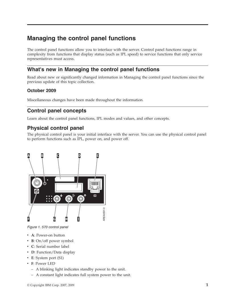
Physical control panelThe physical control panel is your initial interface with the server. You can use the physical control panelto perform functions such as IPL, power on, and power off.
v A: Power-on buttonv B: On/off power symbolv C: Serial number labelv D: Function/Data displayv E: System port (S1)v F: Power LED
– A blinking light indicates standby power to the unit.– A constant light indicates full system power to the unit.
Figure 1. 570 control panel
© Copyright IBM Corp. 2007, 2009 1
Note: There is approximately a 30-second transition period from the time the power-on button ispressed to when the power LED goes from blinking to solid. During the transition period, you mightobserve the blinking intervals speed up.
v G: Decrement buttonv H: Enter buttonv I: Increment button
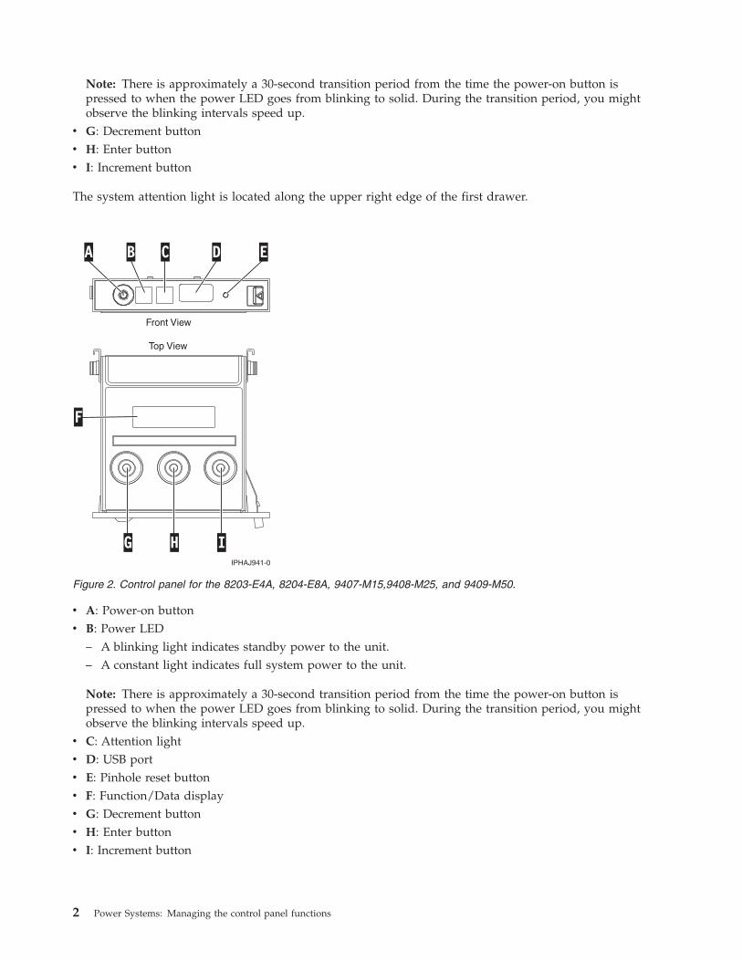
The system attention light is located along the upper right edge of the first drawer.
v A: Power-on buttonv B: Power LED
– A blinking light indicates standby power to the unit.– A constant light indicates full system power to the unit.
Note: There is approximately a 30-second transition period from the time the power-on button ispressed to when the power LED goes from blinking to solid. During the transition period, you mightobserve the blinking intervals speed up.
v C: Attention lightv D: USB portv E: Pinhole reset buttonv F: Function/Data displayv G: Decrement buttonv H: Enter buttonv I: Increment button
Figure 2. Control panel for the 8203-E4A, 8204-E8A, 9407-M15,9408-M25, and 9409-M50.
2 Power Systems: Managing the control panel functions
Accessing the control panel functions using the physical control panelThe control panel functions correspond to function numbers on the control panel.
To activate a control panel function, do the following:1. Select a function number by pressing the Increment (↑) or Decrement (↓) button on the control panel.2. To activate the function, press Enter on the control panel.
Putting the physical control panel in manual operating modeYou must first put the physical control panel in manual operating mode before you can select or activatecertain functions.
To put the physical control panel in manual operating mode, do the following:1. Use the Increment button to scroll to function 02.
0 2 _ _ _ _ _ _ _ _ _ _ _ _ _ __ _ _ _ _ _ _ _ _ _ _ _ _ _ _ _
2. Press Enter to start function 02.3. Press Enter again to move to the second character on the function 02 menu. The current system
operating mode is displayed with a pointer, as shown in the following example:0 2 _ _ B _ _ N < _ _ _ _ _ _ __ _ _ _ _ _ _ _ _ _ _ _ P _ _ _
4. Use the Increment button to scroll through the system operating modes, and select M for manual, asshown in the following example:0 2 _ _ B _ _ M < _ _ _ _ _ _ __ _ _ _ _ _ _ _ _ _ _ _ P _ _ _
5. Press Enter to select the system operating mode.6. Press Enter again to exit function 02.
The control panel is in manual operating mode.Related reference
“Function 02: Select IPL type, IPL speed override, system operating mode, and firmware mode” on page6This function allows you to select the IPL type and logical key mode when the system is either poweredon or off.
Control panel function codesLearn about function codes that are displayed on the control panel to indicate status and functionoptions.
To display all functions, put the control panel in manual operating mode. For details, see Putting thephysical control panel in manual operating mode.
The following table includes descriptions of the primary and customer-extended control panel functioncodes.
Table 1. Primary and customer-extended control panel (32-character) function codes
Function code Function selected
01 Displays the current IPL parameters.
This function is available in both normal and manual operating mode.
02 Used to select the IPL type, system operating mode, IPL speed, and firmware IPLmode. This function is available in both normal and manual operating mode.
Managing the control panel functions 3

Table 1. Primary and customer-extended control panel (32-character) function codes (continued)
Function code Function selected
03 Restarts an IPL of the system using the selected IPL parameters. This function isavailable only in manual operating mode and when the system power is on.
04 Performs a lamp test; all displays and indicators are lit. This function is availablein both normal and manual operating mode.
05 - 06 Reserved.
07 Allows you to perform SPCN service functions. This function is available only inthe manual operating mode and from power on standby.
08 Causes a fast power off. This function is available only when the system is inmanual operating mode and the system power is on.
09 - 10 Reserved.
11 Displays a system reference code (SRC) on the control panel using up to 32 ASCIIcharacters, including non-hexadecimal characters. This function is available in bothnormal and manual operating mode when an SRC is available.
12 Displays an SRC on the control panel using up to four extended SRC data words.This function is available in both normal and manual operating mode when anSRC is available.
13 Displays an SRC on the control panel using up to eight extended SRC data words.This function is available in both normal and manual operating mode when anSRC is available.
14 - 19 Displays an SRC on the control panel using callout data. These functions areavailable in both normal and manual operating mode when an SRC is available.
20 Displays the machine type and model, VPD card CCIN, and IPL types. Thisfunction is available in both normal and manual operating mode.
21 For System i® models, it causes the Use Dedicated Service Tool (DST) display toappear on the system console. To exit the DST, select the Resume operatingsystem display option. This function is available only in the manual operatingmode and when activated by the IBM i operating system.Not applicable forSystem p® servers.
22 Forces a partition dump. For more information on dumps, see Performing dumps.This function is available only in the manual operating mode and when activatedby the operating system.
23 - 24 Reserved.
25 - 26 Use service switches 1 and 2 to enable or disable functions 50 through 99. Thesefunctions are available only in the manual operating mode.
27 - 29 Reserved.
30 Displays the service processor IP address and port location. This function isavailable only in the manual operating mode and in standby.Note: If IPv6 is displayed, then the service processor's network ports areconfigured with IPv6 IP addresses. There are not enough characters on the controlpanel to display the entire address.
31 - 33 Reserved.
34 For System i models, it retries the partition dump. This function is available onlyin the manual operating mode and when activated by the IBM i operatingsystem.Not applicable for System p servers.
35 - 41 Reserved.
42 Performs a platform dump. This function is available only in the manualoperating mode and when activated by the operating system or the serviceprocessor.
4 Power Systems: Managing the control panel functions

Table 1. Primary and customer-extended control panel (32-character) function codes (continued)
Function code Function selected
43 Performs a service processor dump. This function is available only in the manualoperating mode.
44 - 54 Reserved.
55 Displays or changes the platform dump collection policy, platform dumphardware content, and platform dump firmware content settings. This function isavailable only in the manual operating mode.
56 - 62 Reserved.
63 Displays up to the last 25 system status SRCs. This function is available only inthe manual operation mode.
64 Displays up to the last 25 diagnostic status SRCs. This function is available only inthe manual operation mode.
65 - 70 Not applicable.
71 - 99 Reserved.
If you cannot find the function code in this chart, added features or devices might not have beenavailable when this information was produced. Look on the control panel for supplemental unit functioncode information for the function code that you displayed.Related tasks
“Putting the physical control panel in manual operating mode” on page 3You must first put the physical control panel in manual operating mode before you can select or activatecertain functions.
Primary control panel functionsThe primary control panel functions, include displaying the selected IPL type, selecting the firmwaremode, or restarting an IPL.
Function 01: Display selected IPL type, system operating mode, andIPL speedThis function allows you to display the current system operating mode, the IPL speed for the next IPL,the firmware mode for the next IPL, and the operating system IPL mode (when enabled).
This function is available in both normal and manual operating mode.
This function displays the following information:v The operating system (OS) IPL types (A, B, C, or D).v The valid logical key modes (M or N).v The IPL speed (F, V=F, S, V=S, H, V=H, X, or V=X).v The firmware mode (P or T).
Table 2. Function 01 on systems without OS IPL enabled
Function/Data Action or description
0 1 _ _ _ _ _ _ _ _ _ _ _ _ _ __ _ _ _ _ _ _ _ _ _ _ _ _ _ _ _
Use the Increment or Decrement buttons to scroll to function01.
Managing the control panel functions 5

Table 2. Function 01 on systems without OS IPL enabled (continued)
Function/Data Action or description
0 1 _ _ A _ _ M _ _ V = F _ _ __ _ _ _ _ _ _ _ _ _ _ _ P _ _ _
Valid OS IPL types are A, B, C, and D.
Valid system operating modes are M and N.
Valid IPL speed displays are F, V=F, S, V=S, H, and V=H.
Valid firmware IPL modes are P and T.
0 1 _ _ _ _ _ _ _ _ _ _ _ _ _ __ _ _ _ _ _ _ _ _ _ _ _ _ _ _ _
Use the Increment or Decrement buttons to scroll throughthe control panel functions.
Function 02: Select IPL type, IPL speed override, system operatingmode, and firmware modeThis function allows you to select the IPL type and logical key mode when the system is either poweredon or off.
This function is available in both normal and manual operating mode.
Before you can select the IPL speed, the system must be at power on standby.
For powered-on systems, function 02 is used to select the operating system (OS) IPL type, systemoperation mode, or firmware IPL mode. The following table shows an example of the function 02 IPLtype, system operating mode, and firmware IPL mode selection sequence for a powered-on system.
Table 3. Function 02: Select IPL type, system operating mode, and firmware IPL mode on powered-on systems
Function/Data Action or description
0 2 _ _ _ _ _ _ _ _ _ _ _ _ _ __ _ _ _ _ _ _ _ _ _ _ _ _ _ _ _
Use the Increment or Decrement buttons to scroll to function02.
0 2 _ _ A < _ M _ _ _ _ _ _ _ __ _ _ _ _ _ _ _ _ _ _ _ P _ _ _
Press Enter to start function 02.
v The current OS IPL type is displayed with a pointer.
v The current system operating mode is displayed.
v The current firmware mode is displayed.
0 2 _ _ B < _ M _ _ _ _ _ _ _ __ _ _ _ _ _ _ _ _ _ _ _ P _ _ _
Use the Increment or Decrement buttons to scroll throughthe OS IPL types.
0 2 _ _ B _ _ M < _ _ _ _ _ _ __ _ _ _ _ _ _ _ _ _ _ _ P _ _ _
Press Enter to select the OS IPL type.
v The current OS IPL type is displayed.
v The current system operating mode is displayed with apointer.
v The current firmware mode is displayed.
0 2 _ _ B _ _ N < _ _ _ _ _ _ __ _ _ _ _ _ _ _ _ _ _ _ P _ _ _
Use the Increment or Decrement buttons to scroll throughthe system operating modes.
0 2 _ _ B _ _ N _ _ _ _ _ _ _ __ _ _ _ _ _ _ _ _ _ _ _ P < _ _
Press Enter to select the system operating mode.
v The current OS IPL type is displayed.
v The current system operating mode is displayed.
v The current firmware mode is displayed with a pointer.
0 2 _ _ B _ _ N _ _ _ _ _ _ _ __ _ _ _ _ _ _ _ _ _ _ _ T < _ _
Use the Increment or Decrement buttons to scroll throughthe firmware IPL modes.
6 Power Systems: Managing the control panel functions
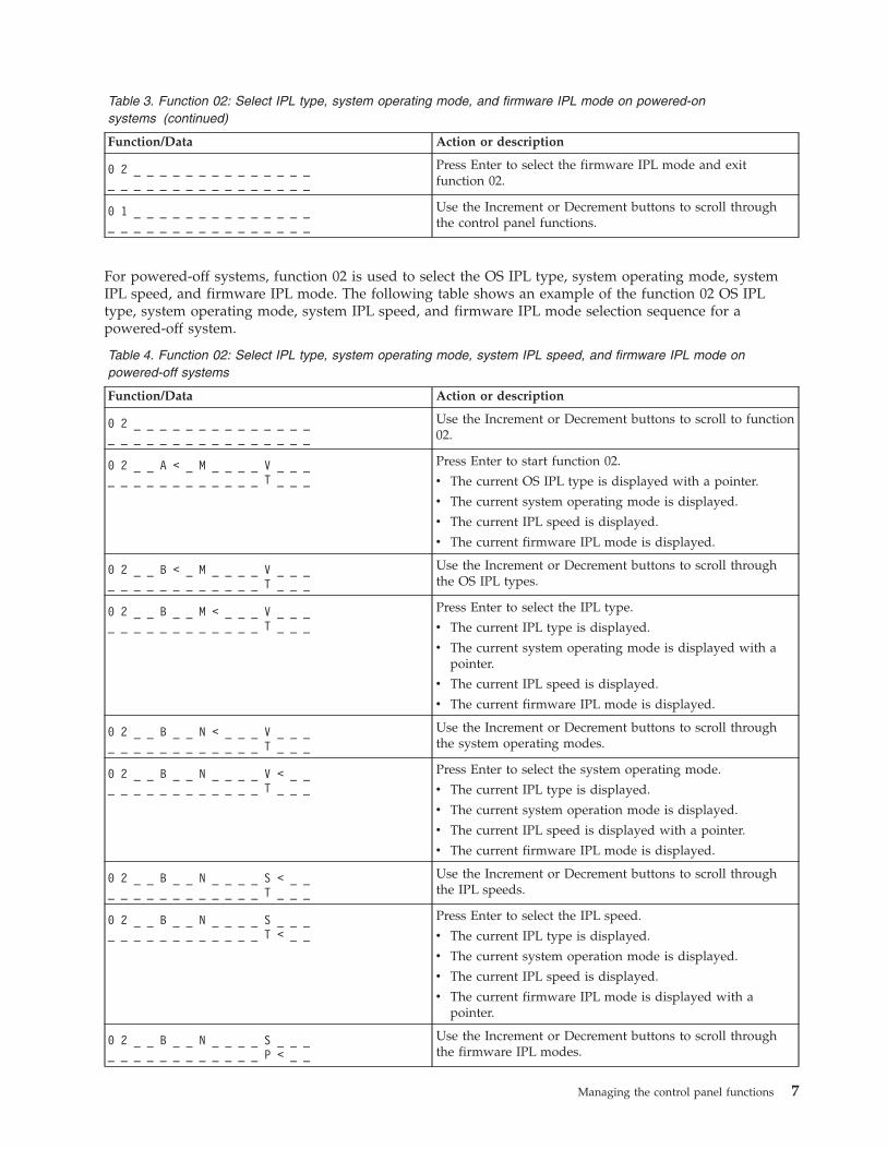
Table 3. Function 02: Select IPL type, system operating mode, and firmware IPL mode on powered-onsystems (continued)
Function/Data Action or description
0 2 _ _ _ _ _ _ _ _ _ _ _ _ _ __ _ _ _ _ _ _ _ _ _ _ _ _ _ _ _
Press Enter to select the firmware IPL mode and exitfunction 02.
0 1 _ _ _ _ _ _ _ _ _ _ _ _ _ __ _ _ _ _ _ _ _ _ _ _ _ _ _ _ _
Use the Increment or Decrement buttons to scroll throughthe control panel functions.
For powered-off systems, function 02 is used to select the OS IPL type, system operating mode, systemIPL speed, and firmware IPL mode. The following table shows an example of the function 02 OS IPLtype, system operating mode, system IPL speed, and firmware IPL mode selection sequence for apowered-off system.
Table 4. Function 02: Select IPL type, system operating mode, system IPL speed, and firmware IPL mode onpowered-off systems
Function/Data Action or description
0 2 _ _ _ _ _ _ _ _ _ _ _ _ _ __ _ _ _ _ _ _ _ _ _ _ _ _ _ _ _
Use the Increment or Decrement buttons to scroll to function02.
0 2 _ _ A < _ M _ _ _ _ V _ _ __ _ _ _ _ _ _ _ _ _ _ _ T _ _ _
Press Enter to start function 02.
v The current OS IPL type is displayed with a pointer.
v The current system operating mode is displayed.
v The current IPL speed is displayed.
v The current firmware IPL mode is displayed.
0 2 _ _ B < _ M _ _ _ _ V _ _ __ _ _ _ _ _ _ _ _ _ _ _ T _ _ _
Use the Increment or Decrement buttons to scroll throughthe OS IPL types.
0 2 _ _ B _ _ M < _ _ _ V _ _ __ _ _ _ _ _ _ _ _ _ _ _ T _ _ _
Press Enter to select the IPL type.
v The current IPL type is displayed.
v The current system operating mode is displayed with apointer.
v The current IPL speed is displayed.
v The current firmware IPL mode is displayed.
0 2 _ _ B _ _ N < _ _ _ V _ _ __ _ _ _ _ _ _ _ _ _ _ _ T _ _ _
Use the Increment or Decrement buttons to scroll throughthe system operating modes.
0 2 _ _ B _ _ N _ _ _ _ V < _ __ _ _ _ _ _ _ _ _ _ _ _ T _ _ _
Press Enter to select the system operating mode.
v The current IPL type is displayed.
v The current system operation mode is displayed.
v The current IPL speed is displayed with a pointer.
v The current firmware IPL mode is displayed.
0 2 _ _ B _ _ N _ _ _ _ S < _ __ _ _ _ _ _ _ _ _ _ _ _ T _ _ _
Use the Increment or Decrement buttons to scroll throughthe IPL speeds.
0 2 _ _ B _ _ N _ _ _ _ S _ _ __ _ _ _ _ _ _ _ _ _ _ _ T < _ _
Press Enter to select the IPL speed.
v The current IPL type is displayed.
v The current system operation mode is displayed.
v The current IPL speed is displayed.
v The current firmware IPL mode is displayed with apointer.
0 2 _ _ B _ _ N _ _ _ _ S _ _ __ _ _ _ _ _ _ _ _ _ _ _ P < _ _
Use the Increment or Decrement buttons to scroll throughthe firmware IPL modes.
Managing the control panel functions 7
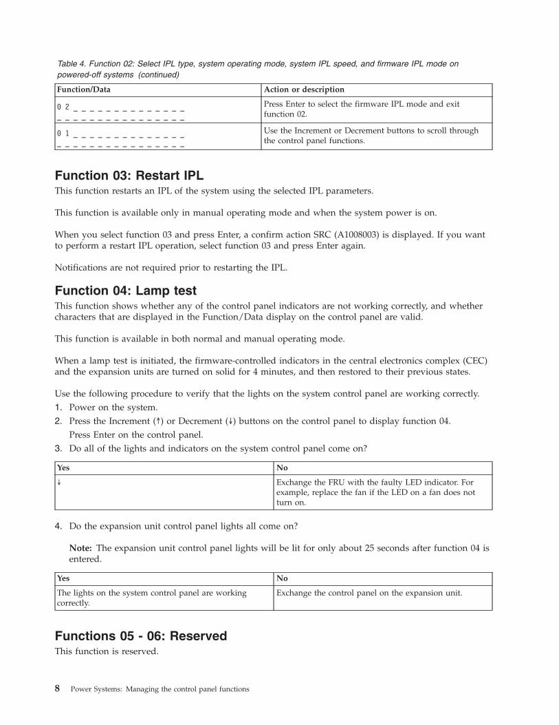
Table 4. Function 02: Select IPL type, system operating mode, system IPL speed, and firmware IPL mode onpowered-off systems (continued)
Function/Data Action or description
0 2 _ _ _ _ _ _ _ _ _ _ _ _ _ __ _ _ _ _ _ _ _ _ _ _ _ _ _ _ _
Press Enter to select the firmware IPL mode and exitfunction 02.
0 1 _ _ _ _ _ _ _ _ _ _ _ _ _ __ _ _ _ _ _ _ _ _ _ _ _ _ _ _ _
Use the Increment or Decrement buttons to scroll throughthe control panel functions.
Function 03: Restart IPLThis function restarts an IPL of the system using the selected IPL parameters.
This function is available only in manual operating mode and when the system power is on.
When you select function 03 and press Enter, a confirm action SRC (A1008003) is displayed. If you wantto perform a restart IPL operation, select function 03 and press Enter again.
Notifications are not required prior to restarting the IPL.
Function 04: Lamp testThis function shows whether any of the control panel indicators are not working correctly, and whethercharacters that are displayed in the Function/Data display on the control panel are valid.
This function is available in both normal and manual operating mode.
When a lamp test is initiated, the firmware-controlled indicators in the central electronics complex (CEC)and the expansion units are turned on solid for 4 minutes, and then restored to their previous states.
Use the following procedure to verify that the lights on the system control panel are working correctly.1. Power on the system.2. Press the Increment (↑) or Decrement (↓) buttons on the control panel to display function 04.
Press Enter on the control panel.3. Do all of the lights and indicators on the system control panel come on?
Yes No
↓ Exchange the FRU with the faulty LED indicator. Forexample, replace the fan if the LED on a fan does notturn on.
4. Do the expansion unit control panel lights all come on?
Note: The expansion unit control panel lights will be lit for only about 25 seconds after function 04 isentered.
Yes No
The lights on the system control panel are workingcorrectly.
Exchange the control panel on the expansion unit.
Functions 05 - 06: ReservedThis function is reserved.
8 Power Systems: Managing the control panel functions
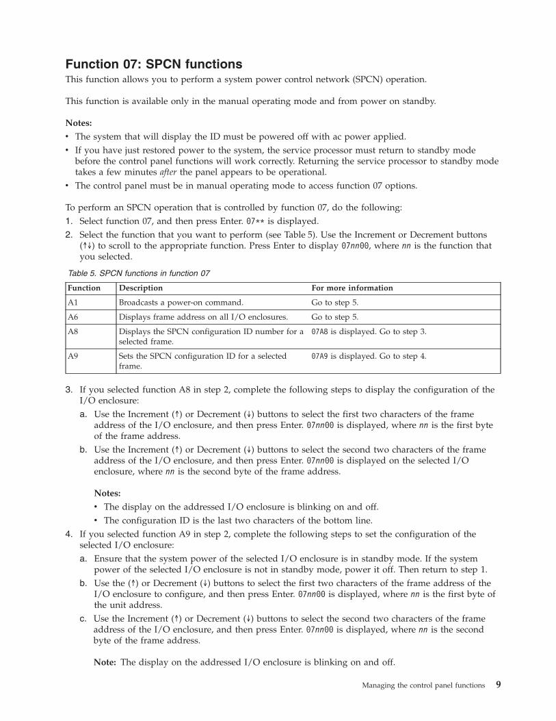
Function 07: SPCN functionsThis function allows you to perform a system power control network (SPCN) operation.
This function is available only in the manual operating mode and from power on standby.
Notes:
v The system that will display the ID must be powered off with ac power applied.v If you have just restored power to the system, the service processor must return to standby mode
before the control panel functions will work correctly. Returning the service processor to standby modetakes a few minutes after the panel appears to be operational.
v The control panel must be in manual operating mode to access function 07 options.
To perform an SPCN operation that is controlled by function 07, do the following:1. Select function 07, and then press Enter. 07** is displayed.2. Select the function that you want to perform (see Table 5). Use the Increment or Decrement buttons
(↑↓) to scroll to the appropriate function. Press Enter to display 07nn00, where nn is the function thatyou selected.
Table 5. SPCN functions in function 07
Function Description For more information
A1 Broadcasts a power-on command. Go to step 5.
A6 Displays frame address on all I/O enclosures. Go to step 5.
A8 Displays the SPCN configuration ID number for aselected frame.
07A8 is displayed. Go to step 3.
A9 Sets the SPCN configuration ID for a selectedframe.
07A9 is displayed. Go to step 4.
3. If you selected function A8 in step 2, complete the following steps to display the configuration of theI/O enclosure:a. Use the Increment (↑) or Decrement (↓) buttons to select the first two characters of the frame
address of the I/O enclosure, and then press Enter. 07nn00 is displayed, where nn is the first byteof the frame address.
b. Use the Increment (↑) or Decrement (↓) buttons to select the second two characters of the frameaddress of the I/O enclosure, and then press Enter. 07nn00 is displayed on the selected I/Oenclosure, where nn is the second byte of the frame address.
Notes:
v The display on the addressed I/O enclosure is blinking on and off.v The configuration ID is the last two characters of the bottom line.
4. If you selected function A9 in step 2, complete the following steps to set the configuration of theselected I/O enclosure:a. Ensure that the system power of the selected I/O enclosure is in standby mode. If the system
power of the selected I/O enclosure is not in standby mode, power it off. Then return to step 1.b. Use the (↑) or Decrement (↓) buttons to select the first two characters of the frame address of the
I/O enclosure to configure, and then press Enter. 07nn00 is displayed, where nn is the first byte ofthe unit address.
c. Use the Increment (↑) or Decrement (↓) buttons to select the second two characters of the frameaddress of the I/O enclosure, and then press Enter. 07nn00 is displayed, where nn is the secondbyte of the frame address.
Note: The display on the addressed I/O enclosure is blinking on and off.
Managing the control panel functions 9
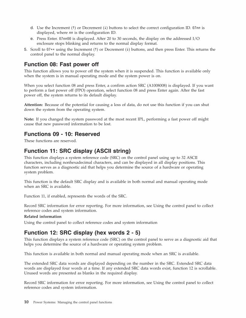
d. Use the Increment (↑) or Decrement (↓) buttons to select the correct configuration ID. 07nn isdisplayed, where nn is the configuration ID.
e. Press Enter. 07nn00 is displayed. After 20 to 30 seconds, the display on the addressed I/Oenclosure stops blinking and returns to the normal display format.
5. Scroll to 07** using the Increment (↑) or Decrement (↓) buttons, and then press Enter. This returns thecontrol panel to the normal display.
Function 08: Fast power offThis function allows you to power off the system when it is suspended. This function is available onlywhen the system is in manual operating mode and the system power is on.
When you select function 08 and press Enter, a confirm action SRC (A1008008) is displayed. If you wantto perform a fast power off (FPO) operation, select function 08 and press Enter again. After the fastpower off, the system returns to its default display.
Attention: Because of the potential for causing a loss of data, do not use this function if you can shutdown the system from the operating system.
Note: If you changed the system password at the most recent IPL, performing a fast power off mightcause that new password information to be lost.
Functions 09 - 10: ReservedThese functions are reserved.
Function 11: SRC display (ASCII string)This function displays a system reference code (SRC) on the control panel using up to 32 ASCIIcharacters, including nonhexadecimal characters, and can be displayed in all display positions. Thisfunction serves as a diagnostic aid that helps you determine the source of a hardware or operatingsystem problem.
This function is the default SRC display and is available in both normal and manual operating modewhen an SRC is available.
Function 11, if enabled, represents the words of the SRC.
Record SRC information for error reporting. For more information, see Using the control panel to collectreference codes and system information.Related information
Using the control panel to collect reference codes and system information
Function 12: SRC display (hex words 2 - 5)This function displays a system reference code (SRC) on the control panel to serve as a diagnostic aid thathelps you determine the source of a hardware or operating system problem.
This function is available in both normal and manual operating mode when an SRC is available.
The extended SRC data words are displayed depending on the number in the SRC. Extended SRC datawords are displayed four words at a time. If any extended SRC data words exist, function 12 is scrollable.Unused words are presented as blanks in the required display.
Record SRC information for error reporting. For more information, see Using the control panel to collectreference codes and system information.
10 Power Systems: Managing the control panel functions
Function 13: SRC display (hex words 6 - 9)This function displays a system reference code (SRC) on the control panel to serve as a diagnostic aid thathelps you determine the source of a hardware or operating system problem.
This function is available in both normal and manual operating mode when an SRC is available.
The extended SRC data words are displayed depending on the number in the SRC. Extended SRC datawords are displayed four words at a time. If there are only one to four extended SRC data words,function 13 is not scrollable. If there are five to eight extended SRC data words, function 13 is scrollable.Unused words are presented as blanks in the required display.
Record SRC information for error reporting. For more information, see Using the control panel to collectreference codes and system information..Related information
Using the control panel to collect reference codes and system information
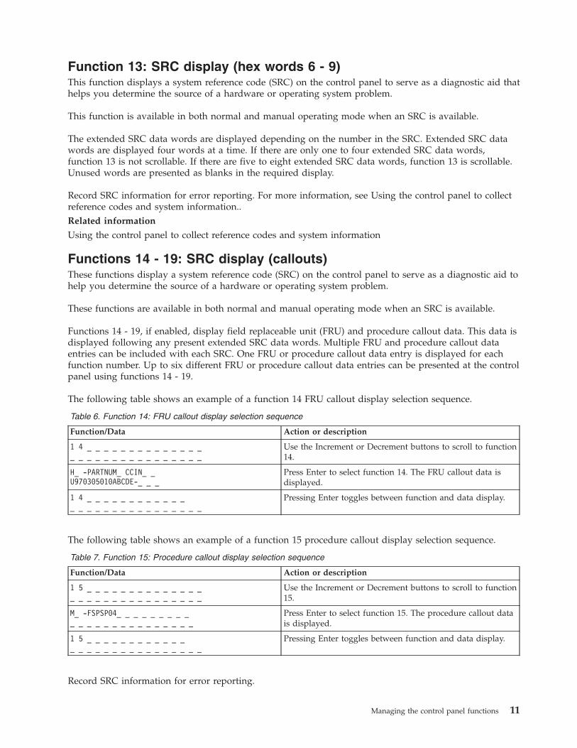
Functions 14 - 19: SRC display (callouts)These functions display a system reference code (SRC) on the control panel to serve as a diagnostic aid tohelp you determine the source of a hardware or operating system problem.
These functions are available in both normal and manual operating mode when an SRC is available.
Functions 14 - 19, if enabled, display field replaceable unit (FRU) and procedure callout data. This data isdisplayed following any present extended SRC data words. Multiple FRU and procedure callout dataentries can be included with each SRC. One FRU or procedure callout data entry is displayed for eachfunction number. Up to six different FRU or procedure callout data entries can be presented at the controlpanel using functions 14 - 19.
The following table shows an example of a function 14 FRU callout display selection sequence.
Table 6. Function 14: FRU callout display selection sequence
Function/Data Action or description
1 4 _ _ _ _ _ _ _ _ _ _ _ _ _ __ _ _ _ _ _ _ _ _ _ _ _ _ _ _ _
Use the Increment or Decrement buttons to scroll to function14.
H_ -PARTNUM_ CCIN_ _U970305010ABCDE-_ _ _
Press Enter to select function 14. The FRU callout data isdisplayed.
1 4 _ _ _ _ _ _ _ _ _ _ _ __ _ _ _ _ _ _ _ _ _ _ _ _ _ _ _
Pressing Enter toggles between function and data display.
The following table shows an example of a function 15 procedure callout display selection sequence.
Table 7. Function 15: Procedure callout display selection sequence
Function/Data Action or description
1 5 _ _ _ _ _ _ _ _ _ _ _ _ _ __ _ _ _ _ _ _ _ _ _ _ _ _ _ _ _
Use the Increment or Decrement buttons to scroll to function15.
M_ -FSPSP04_ _ _ _ _ _ _ _ __ _ _ _ _ _ _ _ _ _ _ _ _ _ _
Press Enter to select function 15. The procedure callout datais displayed.
1 5 _ _ _ _ _ _ _ _ _ _ _ __ _ _ _ _ _ _ _ _ _ _ _ _ _ _ _
Pressing Enter toggles between function and data display.
Record SRC information for error reporting.
Managing the control panel functions 11

Related information
Using the control panel to collect reference codes and system information
Function 20: System type, model, feature code, and IPL typeThis function displays the machine type and model, the custom card identification number (CCIN) forthe vital product data (VPD) card, and IPL types. This function is available in both normal and manualoperating mode.
The machine type, model, CCIN for the VPD card, and IPL type are displayed in the following format:
p p p p - m m m _ _ _ _ c c c c
T T T T T T T T t t t t t t t t
The values are indicated as follows:v Values for p indicate the machine type.v Values for m indicate the machine model.v Values for c indicate the system CCIN for the VPD card.v Values for T indicate the CEC IPL type.v Values for t indicate the FSP IPL type.
Record this information with the system reference code (SRC).
If you select this function and it has not been activated, the command is rejected.
Customer-extended panel functionsThe customer-extended panel functions include partition dumps, service processor IP address and portlocation.
Function 21: Service tool initiationFor System i models, this function makes dedicated service tools (DST) available on the system consoledisplay.For System p servers, it is not applicable.
This function is available only in the manual operating mode and when activated by the operatingsystem.
The Use dedicated service tools (DST) display is available on the primary or alternative console.
To exit the DST and return to the operating system, select the Resume operating system display optionon the Use dedicated service tools (DST) display.
Function 22: Partition dumpThis function initiates a dump of the operating system data in a logical partition.
This function is available only in the manual operating mode and when activated by the operatingsystem.
You must perform two consecutive function 22 selections to initiate a partition dump. The following tableshows an example of function 22.
12 Power Systems: Managing the control panel functions
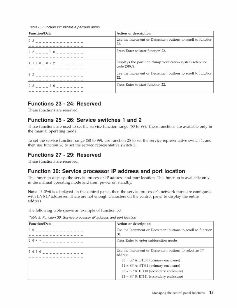
Table 8. Function 22: Initiate a partition dump
Function/Data Action or description
2 2 _ _ _ _ _ _ _ _ _ _ _ _ _ __ _ _ _ _ _ _ _ _ _ _ _ _ _ _ _
Use the Increment or Decrement buttons to scroll to function22.
2 2 _ _ _ _ 0 0 _ _ _ _ _ _ _ __ _ _ _ _ _ _ _ _ _ _ _ _ _ _ _
Press Enter to start function 22.
A 1 0 0 3 0 2 2 _ _ _ _ _ _ _ __ _ _ _ _ _ _ _ _ _ _ _ _ _ _ _
Displays the partition dump verification system referencecode (SRC).
2 2 _ _ _ _ _ _ _ _ _ _ _ _ _ __ _ _ _ _ _ _ _ _ _ _ _ _ _ _ _
Use the Increment or Decrement buttons to scroll to function22.
2 2 _ _ _ _ 0 0 _ _ _ _ _ _ _ __ _ _ _ _ _ _ _ _ _ _ _ _ _ _ _
Press Enter to start function 22.
Functions 23 - 24: ReservedThese functions are reserved.
Functions 25 - 26: Service switches 1 and 2These functions are used to set the service function range (50 to 99). These functions are available only inthe manual operating mode.
To set the service function range (50 to 99), use function 25 to set the service representative switch 1, andthen use function 26 to set the service representative switch 2.
Functions 27 - 29: ReservedThese functions are reserved.
Function 30: Service processor IP address and port locationThis function displays the service processor IP address and port location. This function is available onlyin the manual operating mode and from power on standby.
Note: If IPv6 is displayed on the control panel, then the service processor's network ports are configuredwith IPv6 IP addresses. There are not enough characters on the control panel to display the entireaddress.
The following table shows an example of function 30.
Table 9. Function 30: Service processor IP address and port location
Function/Data Action or description
3 0 _ _ _ _ _ _ _ _ _ _ _ _ _ __ _ _ _ _ _ _ _ _ _ _ _ _ _ _ _
Use the Increment or Decrement buttons to scroll to function30.
3 0 * * _ _ _ _ _ _ _ _ _ _ _ __ _ _ _ _ _ _ _ _ _ _ _ _ _ _ _
Press Enter to enter subfunction mode.
3 0 0 0 _ _ _ _ _ _ _ _ _ _ _ __ _ _ _ _ _ _ _ _ _ _ _ _ _ _ _
Use the Increment or Decrement buttons to select an IPaddress
00 = SP A: ETH0 (primary enclosure)
01 = SP A: ETH1 (primary enclosure)
02 = SP B: ETH0 (secondary enclosure)
03 = SP B: ETH1 (secondary enclosure)
Managing the control panel functions 13
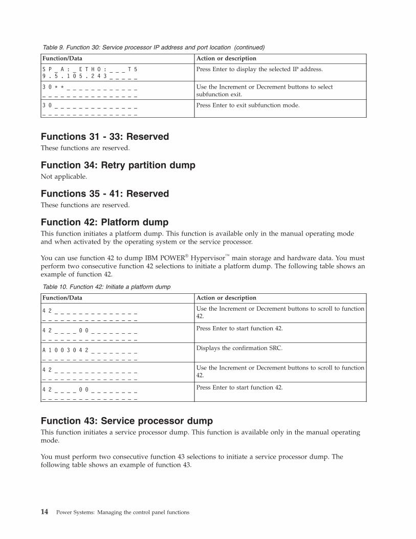
Table 9. Function 30: Service processor IP address and port location (continued)
Function/Data Action or description
S P _ A : _ E T H O : _ _ _ T 59 . 5 . 1 0 5 . 2 4 3 _ _ _ _ _
Press Enter to display the selected IP address.
3 0 * * _ _ _ _ _ _ _ _ _ _ _ __ _ _ _ _ _ _ _ _ _ _ _ _ _ _ _
Use the Increment or Decrement buttons to selectsubfunction exit.
3 0 _ _ _ _ _ _ _ _ _ _ _ _ _ __ _ _ _ _ _ _ _ _ _ _ _ _ _ _ _
Press Enter to exit subfunction mode.
Functions 31 - 33: ReservedThese functions are reserved.
Function 34: Retry partition dumpNot applicable.
Functions 35 - 41: ReservedThese functions are reserved.
Function 42: Platform dumpThis function initiates a platform dump. This function is available only in the manual operating modeand when activated by the operating system or the service processor.
You can use function 42 to dump IBM POWER® Hypervisor™ main storage and hardware data. You mustperform two consecutive function 42 selections to initiate a platform dump. The following table shows anexample of function 42.
Table 10. Function 42: Initiate a platform dump
Function/Data Action or description
4 2 _ _ _ _ _ _ _ _ _ _ _ _ _ __ _ _ _ _ _ _ _ _ _ _ _ _ _ _ _
Use the Increment or Decrement buttons to scroll to function42.
4 2 _ _ _ _ 0 0 _ _ _ _ _ _ _ __ _ _ _ _ _ _ _ _ _ _ _ _ _ _ _
Press Enter to start function 42.
A 1 0 0 3 0 4 2 _ _ _ _ _ _ _ __ _ _ _ _ _ _ _ _ _ _ _ _ _ _ _
Displays the confirmation SRC.
4 2 _ _ _ _ _ _ _ _ _ _ _ _ _ __ _ _ _ _ _ _ _ _ _ _ _ _ _ _ _
Use the Increment or Decrement buttons to scroll to function42.
4 2 _ _ _ _ 0 0 _ _ _ _ _ _ _ __ _ _ _ _ _ _ _ _ _ _ _ _ _ _ _
Press Enter to start function 42.
Function 43: Service processor dumpThis function initiates a service processor dump. This function is available only in the manual operatingmode.
You must perform two consecutive function 43 selections to initiate a service processor dump. Thefollowing table shows an example of function 43.
14 Power Systems: Managing the control panel functions

Table 11. Function 43: Initiate a service processor dump
Function/Data Action or description
4 3 _ _ _ _ _ _ _ _ _ _ _ _ _ __ _ _ _ _ _ _ _ _ _ _ _ _ _ _ _
Use the Increment or Decrement buttons to scroll to function43.
4 3 0 0 _ _ _ _ __ _ _ _ _ _ __ _ _ _ _ _ _ _ _ _ _ _ _ _ _ _
Press Enter to confirm.
A 1 0 0 3 0 4 3 _ _ _ _ _ _ _ __ _ _ _ _ _ _ _ _ _ _ _ _ _ _ _
Displays the confirmation system reference code (SRC).
4 3 _ _ _ _ _ _ _ _ _ _ _ _ _ __ _ _ _ _ _ _ _ _ _ _ _ _ _ _ _
Use the Increment or Decrement buttons to scroll to function43.
4 3 0 0 _ _ _ _ _ _ _ _ _ _ _ __ _ _ _ _ _ _ _ _ _ _ _ _ _ _ _
Press Enter to confirm.
Functions 44 - 54: ReservedThese functions are reserved.
Function 55: View and change platform dump dataThis function allows you to view and change the platform dump data. This function is available only inthe manual operating mode.
When you select function 55 and press Enter, you can view and change the platform dump collectionpolicy, platform dump hardware content, and platform dump firmware content settings.
The following table shows an example of how to view the platform dump data.
Table 12. Function 55: View the platform dump data
Function/Data Action or description
5 5 _ _ _ _ _ _ _ _ _ _ _ _ _ __ _ _ _ _ _ _ _ _ _ _ _ _ _ _ _
Use the Increment or Decrement buttons to scroll to function55.
5 5 * * _ _ _ _ _ _ _ _ _ _ _ __ _ _ _ _ _ _ _ _ _ _ _ _ _ _ _
Press Enter to enter subfunction mode.
5 5 0 0 _ _ _ _ _ _ _ _ _ _ _ __ _ _ _ _ _ _ _ _ _ _ _ _ _ _ _
Use the Increment or Decrement buttons to view theplatform dump variables.
5 5 0 0 _ xxyyzz_ _ _ _ _ _ __ _ _ _ _ _ _ _ _ _ _ _ _ _ _ _
Press Enter to process the selected subfunction.
xx = Collection policy
yy = Hardware content
zz = Firmware content
5 5 * * _ _ _ _ _ _ _ _ _ _ _ __ _ _ _ _ _ _ _ _ _ _ _ _ _ _ _
Use the Increment or Decrement buttons to selectsubfunction exit.
5 5 _ _ _ _ _ _ _ _ _ _ _ _ _ __ _ _ _ _ _ _ _ _ _ _ _ _ _ _ _
Press Enter to exit subfunction mode.
The following table shows an example of how to change the platform dump data.
Table 13. Function 55: Change the platform dump data
Function/Data Action or description
5 5 _ _ _ _ _ _ _ _ _ _ _ _ _ __ _ _ _ _ _ _ _ _ _ _ _ _ _ _ _
Use the Increment or Decrement buttons to scroll to function55.
Managing the control panel functions 15
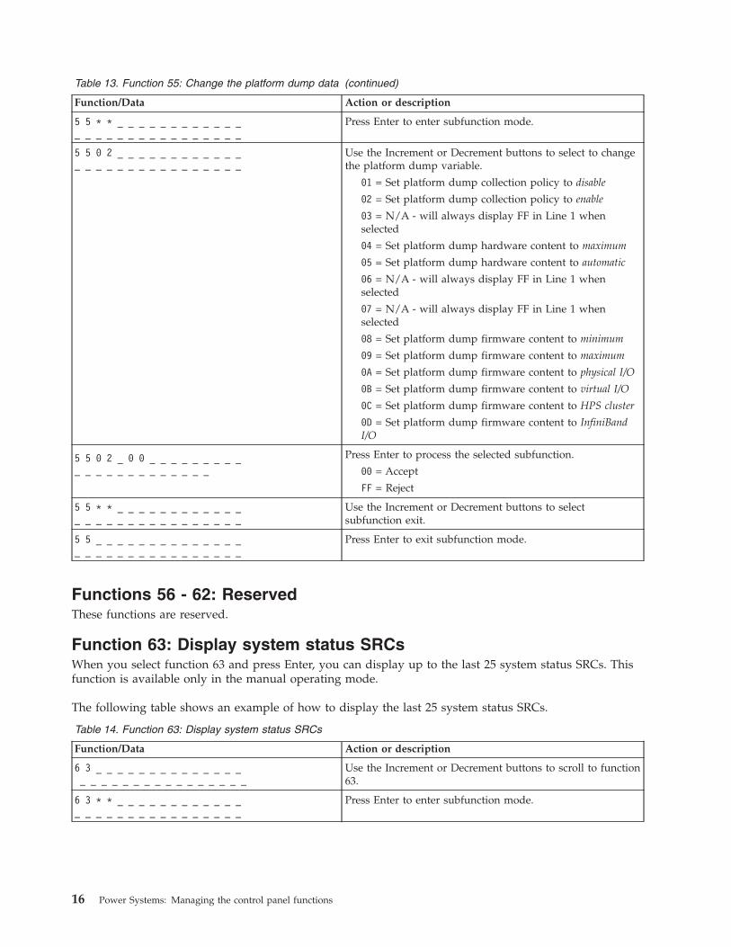
Table 13. Function 55: Change the platform dump data (continued)
Function/Data Action or description
5 5 * * _ _ _ _ _ _ _ _ _ _ _ __ _ _ _ _ _ _ _ _ _ _ _ _ _ _ _
Press Enter to enter subfunction mode.
5 5 0 2 _ _ _ _ _ _ _ _ _ _ _ __ _ _ _ _ _ _ _ _ _ _ _ _ _ _ _
Use the Increment or Decrement buttons to select to changethe platform dump variable.
01 = Set platform dump collection policy to disable
02 = Set platform dump collection policy to enable
03 = N/A - will always display FF in Line 1 whenselected
04 = Set platform dump hardware content to maximum
05 = Set platform dump hardware content to automatic
06 = N/A - will always display FF in Line 1 whenselected
07 = N/A - will always display FF in Line 1 whenselected
08 = Set platform dump firmware content to minimum
09 = Set platform dump firmware content to maximum
0A = Set platform dump firmware content to physical I/O
0B = Set platform dump firmware content to virtual I/O
0C = Set platform dump firmware content to HPS cluster
0D = Set platform dump firmware content to InfiniBandI/O
5 5 0 2 _ 0 0 _ _ _ _ _ _ _ _ __ _ _ _ _ _ _ _ _ _ _ _ _
Press Enter to process the selected subfunction.
00 = Accept
FF = Reject
5 5 * * _ _ _ _ _ _ _ _ _ _ _ __ _ _ _ _ _ _ _ _ _ _ _ _ _ _ _
Use the Increment or Decrement buttons to selectsubfunction exit.
5 5 _ _ _ _ _ _ _ _ _ _ _ _ _ __ _ _ _ _ _ _ _ _ _ _ _ _ _ _ _
Press Enter to exit subfunction mode.
Functions 56 - 62: ReservedThese functions are reserved.
Function 63: Display system status SRCsWhen you select function 63 and press Enter, you can display up to the last 25 system status SRCs. Thisfunction is available only in the manual operating mode.
The following table shows an example of how to display the last 25 system status SRCs.
Table 14. Function 63: Display system status SRCs
Function/Data Action or description
6 3 _ _ _ _ _ _ _ _ _ _ _ _ _ __ _ _ _ _ _ _ _ _ _ _ _ _ _ _ _
Use the Increment or Decrement buttons to scroll to function63.
6 3 * * _ _ _ _ _ _ _ _ _ _ _ __ _ _ _ _ _ _ _ _ _ _ _ _ _ _ _
Press Enter to enter subfunction mode.
16 Power Systems: Managing the control panel functions
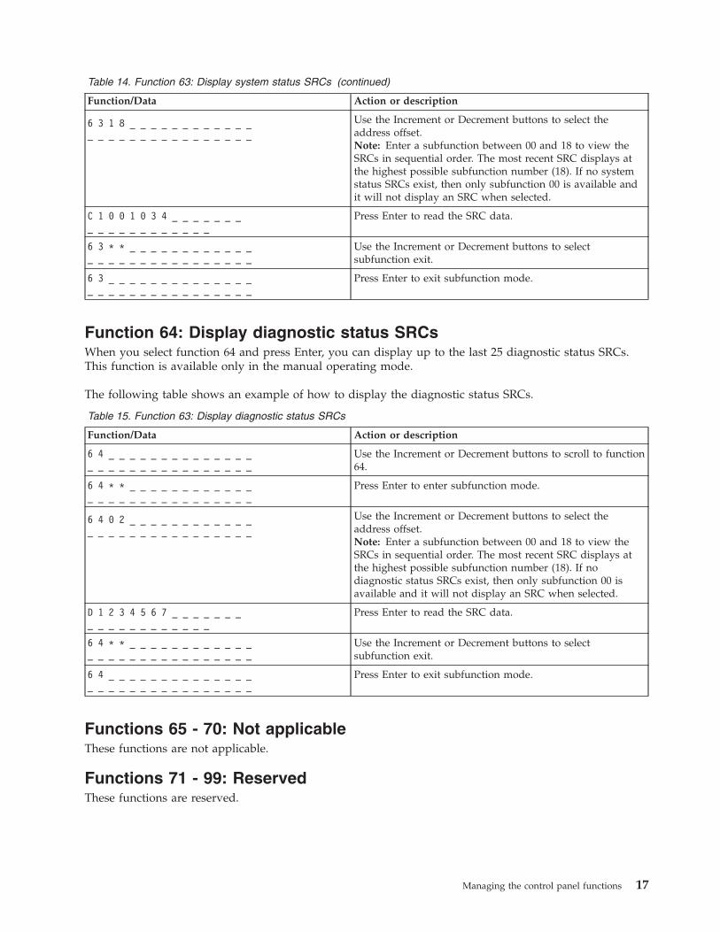
Table 14. Function 63: Display system status SRCs (continued)
Function/Data Action or description
6 3 1 8 _ _ _ _ _ _ _ _ _ _ _ __ _ _ _ _ _ _ _ _ _ _ _ _ _ _ _
Use the Increment or Decrement buttons to select theaddress offset.Note: Enter a subfunction between 00 and 18 to view theSRCs in sequential order. The most recent SRC displays atthe highest possible subfunction number (18). If no systemstatus SRCs exist, then only subfunction 00 is available andit will not display an SRC when selected.
C 1 0 0 1 0 3 4 _ _ _ _ _ _ __ _ _ _ _ _ _ _ _ _ _ _
Press Enter to read the SRC data.
6 3 * * _ _ _ _ _ _ _ _ _ _ _ __ _ _ _ _ _ _ _ _ _ _ _ _ _ _ _
Use the Increment or Decrement buttons to selectsubfunction exit.
6 3 _ _ _ _ _ _ _ _ _ _ _ _ _ __ _ _ _ _ _ _ _ _ _ _ _ _ _ _ _
Press Enter to exit subfunction mode.
Function 64: Display diagnostic status SRCsWhen you select function 64 and press Enter, you can display up to the last 25 diagnostic status SRCs.This function is available only in the manual operating mode.
The following table shows an example of how to display the diagnostic status SRCs.
Table 15. Function 63: Display diagnostic status SRCs
Function/Data Action or description
6 4 _ _ _ _ _ _ _ _ _ _ _ _ _ __ _ _ _ _ _ _ _ _ _ _ _ _ _ _ _
Use the Increment or Decrement buttons to scroll to function64.
6 4 * * _ _ _ _ _ _ _ _ _ _ _ __ _ _ _ _ _ _ _ _ _ _ _ _ _ _ _
Press Enter to enter subfunction mode.
6 4 0 2 _ _ _ _ _ _ _ _ _ _ _ __ _ _ _ _ _ _ _ _ _ _ _ _ _ _ _
Use the Increment or Decrement buttons to select theaddress offset.Note: Enter a subfunction between 00 and 18 to view theSRCs in sequential order. The most recent SRC displays atthe highest possible subfunction number (18). If nodiagnostic status SRCs exist, then only subfunction 00 isavailable and it will not display an SRC when selected.
D 1 2 3 4 5 6 7 _ _ _ _ _ _ __ _ _ _ _ _ _ _ _ _ _ _
Press Enter to read the SRC data.
6 4 * * _ _ _ _ _ _ _ _ _ _ _ __ _ _ _ _ _ _ _ _ _ _ _ _ _ _ _
Use the Increment or Decrement buttons to selectsubfunction exit.
6 4 _ _ _ _ _ _ _ _ _ _ _ _ _ __ _ _ _ _ _ _ _ _ _ _ _ _ _ _ _
Press Enter to exit subfunction mode.
Functions 65 - 70: Not applicableThese functions are not applicable.
Functions 71 - 99: ReservedThese functions are reserved.
Managing the control panel functions 17
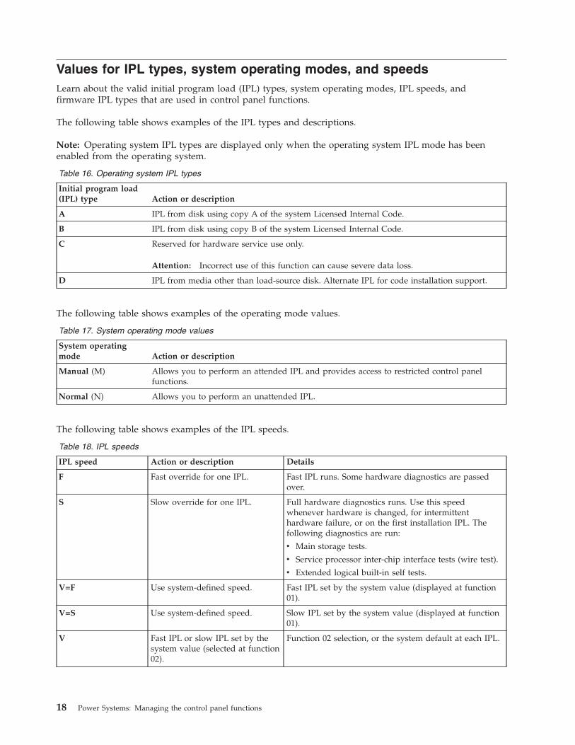
Values for IPL types, system operating modes, and speedsLearn about the valid initial program load (IPL) types, system operating modes, IPL speeds, andfirmware IPL types that are used in control panel functions.
The following table shows examples of the IPL types and descriptions.
Note: Operating system IPL types are displayed only when the operating system IPL mode has beenenabled from the operating system.
Table 16. Operating system IPL types
Initial program load(IPL) type Action or description
A IPL from disk using copy A of the system Licensed Internal Code.
B IPL from disk using copy B of the system Licensed Internal Code.
C Reserved for hardware service use only.
Attention: Incorrect use of this function can cause severe data loss.
D IPL from media other than load-source disk. Alternate IPL for code installation support.
The following table shows examples of the operating mode values.
Table 17. System operating mode values
System operatingmode Action or description
Manual (M) Allows you to perform an attended IPL and provides access to restricted control panelfunctions.
Normal (N) Allows you to perform an unattended IPL.
The following table shows examples of the IPL speeds.
Table 18. IPL speeds
IPL speed Action or description Details
F Fast override for one IPL. Fast IPL runs. Some hardware diagnostics are passedover.
S Slow override for one IPL. Full hardware diagnostics runs. Use this speedwhenever hardware is changed, for intermittenthardware failure, or on the first installation IPL. Thefollowing diagnostics are run:
v Main storage tests.
v Service processor inter-chip interface tests (wire test).
v Extended logical built-in self tests.
V=F Use system-defined speed. Fast IPL set by the system value (displayed at function01).
V=S Use system-defined speed. Slow IPL set by the system value (displayed at function01).
V Fast IPL or slow IPL set by thesystem value (selected at function02).
Function 02 selection, or the system default at each IPL.
18 Power Systems: Managing the control panel functions
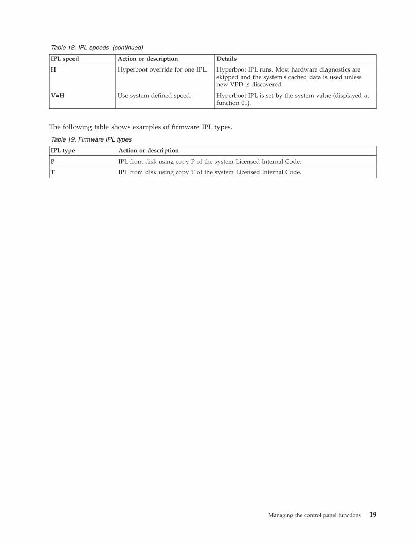
Table 18. IPL speeds (continued)
IPL speed Action or description Details
H Hyperboot override for one IPL. Hyperboot IPL runs. Most hardware diagnostics areskipped and the system's cached data is used unlessnew VPD is discovered.
V=H Use system-defined speed. Hyperboot IPL is set by the system value (displayed atfunction 01).
The following table shows examples of firmware IPL types.
Table 19. Firmware IPL types
IPL type Action or description
P IPL from disk using copy P of the system Licensed Internal Code.
T IPL from disk using copy T of the system Licensed Internal Code.
Managing the control panel functions 19

20 Power Systems: Managing the control panel functions

Appendix. Notices
This information was developed for products and services offered in the U.S.A.
The manufacturer may not offer the products, services, or features discussed in this document in othercountries. Consult the manufacturer's representative for information on the products and servicescurrently available in your area. Any reference to the manufacturer's product, program, or service is notintended to state or imply that only that product, program, or service may be used. Any functionallyequivalent product, program, or service that does not infringe any intellectual property right of themanufacturer may be used instead. However, it is the user's responsibility to evaluate and verify theoperation of any product, program, or service.
The manufacturer may have patents or pending patent applications covering subject matter described inthis document. The furnishing of this document does not grant you any license to these patents. You cansend license inquiries, in writing, to the manufacturer.
The following paragraph does not apply to the United Kingdom or any other country where suchprovisions are inconsistent with local law: THIS INFORMATION IS PROVIDED “AS IS” WITHOUTWARRANTY OF ANY KIND, EITHER EXPRESS OR IMPLIED, INCLUDING, BUT NOT LIMITED TO,THE IMPLIED WARRANTIES OF NON-INFRINGEMENT, MERCHANTABILITY OR FITNESS FOR APARTICULAR PURPOSE. Some states do not allow disclaimer of express or implied warranties in certaintransactions, therefore, this statement may not apply to you.
This information could include technical inaccuracies or typographical errors. Changes are periodicallymade to the information herein; these changes will be incorporated in new editions of the publication.The manufacturer may make improvements and/or changes in the product(s) and/or the program(s)described in this publication at any time without notice.
Any references in this information to Web sites not owned by the manufacturer are provided forconvenience only and do not in any manner serve as an endorsement of those Web sites. The materials atthose Web sites are not part of the materials for this product and use of those Web sites is at your ownrisk.
The manufacturer may use or distribute any of the information you supply in any way it believesappropriate without incurring any obligation to you.
Any performance data contained herein was determined in a controlled environment. Therefore, theresults obtained in other operating environments may vary significantly. Some measurements may havebeen made on development-level systems and there is no guarantee that these measurements will be thesame on generally available systems. Furthermore, some measurements may have been estimated throughextrapolation. Actual results may vary. Users of this document should verify the applicable data for theirspecific environment.
Information concerning products not produced by this manufacturer was obtained from the suppliers ofthose products, their published announcements or other publicly available sources. This manufacturer hasnot tested those products and cannot confirm the accuracy of performance, compatibility or any otherclaims related to products not produced by this manufacturer. Questions on the capabilities of productsnot produced by this manufacturer should be addressed to the suppliers of those products.
All statements regarding the manufacturer's future direction or intent are subject to change or withdrawalwithout notice, and represent goals and objectives only.
© Copyright IBM Corp. 2007, 2009 21

The manufacturer's prices shown are the manufacturer's suggested retail prices, are current and aresubject to change without notice. Dealer prices may vary.
This information is for planning purposes only. The information herein is subject to change before theproducts described become available.
This information contains examples of data and reports used in daily business operations. To illustratethem as completely as possible, the examples include the names of individuals, companies, brands, andproducts. All of these names are fictitious and any similarity to the names and addresses used by anactual business enterprise is entirely coincidental.
If you are viewing this information in softcopy, the photographs and color illustrations may not appear.
The drawings and specifications contained herein shall not be reproduced in whole or in part without thewritten permission of the manufacturer.
The manufacturer has prepared this information for use with the specific machines indicated. Themanufacturer makes no representations that it is suitable for any other purpose.
The manufacturer's computer systems contain mechanisms designed to reduce the possibility ofundetected data corruption or loss. This risk, however, cannot be eliminated. Users who experienceunplanned outages, system failures, power fluctuations or outages, or component failures must verify theaccuracy of operations performed and data saved or transmitted by the system at or near the time of theoutage or failure. In addition, users must establish procedures to ensure that there is independent dataverification before relying on such data in sensitive or critical operations. Users should periodically checkthe manufacturer's support websites for updated information and fixes applicable to the system andrelated software.
TrademarksIBM, the IBM logo, and ibm.com are trademarks or registered trademarks of International BusinessMachines Corp., registered in many jurisdictions worldwide. Other product and service names might betrademarks of IBM or other companies. A current list of IBM trademarks is available on the Web atCopyright and trademark information at www.ibm.com/legal/copytrade.shtml.
INFINIBAND, InfiniBand Trade Association, and the INFINIBAND design marks are trademarks and/orservice marks of the INFINIBAND Trade Association.
Other company, product, or service names may be trademarks or service marks of others.
Electronic emission notices
Class A NoticesThe following Class A statements apply to the IBM servers that contain the POWER6 processor.
Federal Communications Commission (FCC) statement
Note: This equipment has been tested and found to comply with the limits for a Class A digital device,pursuant to Part 15 of the FCC Rules. These limits are designed to provide reasonable protection againstharmful interference when the equipment is operated in a commercial environment. This equipmentgenerates, uses, and can radiate radio frequency energy and, if not installed and used in accordance withthe instruction manual, may cause harmful interference to radio communications. Operation of thisequipment in a residential area is likely to cause harmful interference, in which case the user will berequired to correct the interference at his own expense.
22 Power Systems: Managing the control panel functions

Properly shielded and grounded cables and connectors must be used in order to meet FCC emissionlimits. IBM is not responsible for any radio or television interference caused by using other thanrecommended cables and connectors or by unauthorized changes or modifications to this equipment.Unauthorized changes or modifications could void the user's authority to operate the equipment.
This device complies with Part 15 of the FCC rules. Operation is subject to the following two conditions:(1) this device may not cause harmful interference, and (2) this device must accept any interferencereceived, including interference that may cause undesired operation.
Industry Canada Compliance Statement
This Class A digital apparatus complies with Canadian ICES-003.
Avis de conformité à la réglementation d'Industrie Canada
Cet appareil numérique de la classe A respecte est conforme à la norme NMB-003 du Canada.
European Community Compliance Statement
This product is in conformity with the protection requirements of EU Council Directive 2004/108/EC onthe approximation of the laws of the Member States relating to electromagnetic compatibility. IBM cannotaccept responsibility for any failure to satisfy the protection requirements resulting from anon-recommended modification of the product, including the fitting of non-IBM option cards.
This product has been tested and found to comply with the limits for Class A Information TechnologyEquipment according to European Standard EN 55022. The limits for Class A equipment were derived forcommercial and industrial environments to provide reasonable protection against interference withlicensed communication equipment.
European Community contact:IBM Technical RegulationsPascalstr. 100, Stuttgart, Germany 70569Tele: 0049 (0)711 785 1176Fax: 0049 (0)711 785 1283E-mail: [email protected]
Warning: This is a Class A product. In a domestic environment, this product may cause radiointerference, in which case the user may be required to take adequate measures.
VCCI Statement - Japan
The following is a summary of the VCCI Japanese statement in the box above:
This is a Class A product based on the standard of the VCCI Council. If this equipment is used in adomestic environment, radio interference may occur, in which case, the user may be required to takecorrective actions.
Appendix. Notices 23

Japanese Electronics and Information Technology Industries Association (JEITA)Confirmed Harmonics Guideline (products less than or equal to 20 A per phase)
Japanese Electronics and Information Technology Industries Association (JEITA)Confirmed Harmonics Guideline with Modifications (products greater than 20 A perphase)
Electromagnetic Interference (EMI) Statement - People's Republic of China
Declaration: This is a Class A product. In a domestic environment this product may cause radiointerference in which case the user may need to perform practical action.
Electromagnetic Interference (EMI) Statement - Taiwan
The following is a summary of the EMI Taiwan statement above.
Warning: This is a Class A product. In a domestic environment this product may cause radio interferencein which case the user will be required to take adequate measures.
IBM Taiwan Contact Information:
24 Power Systems: Managing the control panel functions

Electromagnetic Interference (EMI) Statement - Korea
Please note that this equipment has obtained EMC registration for commercial use. In the event that ithas been mistakenly sold or purchased, please exchange it for equipment certified for home use.
Germany Compliance Statement
Deutschsprachiger EU Hinweis: Hinweis für Geräte der Klasse A EU-Richtlinie zurElektromagnetischen Verträglichkeit
Dieses Produkt entspricht den Schutzanforderungen der EU-Richtlinie 2004/108/EG zur Angleichung derRechtsvorschriften über die elektromagnetische Verträglichkeit in den EU-Mitgliedsstaaten und hält dieGrenzwerte der EN 55022 Klasse A ein.
Um dieses sicherzustellen, sind die Geräte wie in den Handbüchern beschrieben zu installieren und zubetreiben. Des Weiteren dürfen auch nur von der IBM empfohlene Kabel angeschlossen werden. IBMübernimmt keine Verantwortung für die Einhaltung der Schutzanforderungen, wenn das Produkt ohneZustimmung der IBM verändert bzw. wenn Erweiterungskomponenten von Fremdherstellern ohneEmpfehlung der IBM gesteckt/eingebaut werden.
EN 55022 Klasse A Geräte müssen mit folgendem Warnhinweis versehen werden:"Warnung: Dieses ist eine Einrichtung der Klasse A. Diese Einrichtung kann im WohnbereichFunk-Störungen verursachen; in diesem Fall kann vom Betreiber verlangt werden, angemesseneMaßnahmen zu ergreifen und dafür aufzukommen."
Deutschland: Einhaltung des Gesetzes über die elektromagnetische Verträglichkeit von Geräten
Dieses Produkt entspricht dem “Gesetz über die elektromagnetische Verträglichkeit von Geräten(EMVG)“. Dies ist die Umsetzung der EU-Richtlinie 2004/108/EG in der Bundesrepublik Deutschland.
Zulassungsbescheinigung laut dem Deutschen Gesetz über die elektromagnetische Verträglichkeit vonGeräten (EMVG) (bzw. der EMC EG Richtlinie 2004/108/EG) für Geräte der Klasse A.
Dieses Gerät ist berechtigt, in Übereinstimmung mit dem Deutschen EMVG das EG-Konformitätszeichen- CE - zu führen.
Verantwortlich für die Konformitätserklärung nach des EMVG ist die IBM Deutschland GmbH, 70548Stuttgart.
Appendix. Notices 25

Generelle Informationen:
Das Gerät erfüllt die Schutzanforderungen nach EN 55024 und EN 55022 Klasse A.
Electromagnetic Interference (EMI) Statement - Russia
Terms and conditionsPermissions for the use of these publications is granted subject to the following terms and conditions.
Personal Use: You may reproduce these publications for your personal, noncommercial use provided thatall proprietary notices are preserved. You may not distribute, display or make derivative works of thesepublications, or any portion thereof, without the express consent of the manufacturer.
Commercial Use: You may reproduce, distribute and display these publications solely within yourenterprise provided that all proprietary notices are preserved. You may not make derivative works ofthese publications, or reproduce, distribute or display these publications or any portion thereof outsideyour enterprise, without the express consent of the manufacturer.
Except as expressly granted in this permission, no other permissions, licenses or rights are granted, eitherexpress or implied, to the publications or any data, software or other intellectual property containedtherein.
The manufacturer reserves the right to withdraw the permissions granted herein whenever, in itsdiscretion, the use of the publications is detrimental to its interest or, as determined by the manufacturer,the above instructions are not being properly followed.
You may not download, export or re-export this information except in full compliance with all applicablelaws and regulations, including all United States export laws and regulations.
THE MANUFACTURER MAKES NO GUARANTEE ABOUT THE CONTENT OF THESEPUBLICATIONS. THESE PUBLICATIONS ARE PROVIDED "AS-IS" AND WITHOUT WARRANTY OFANY KIND, EITHER EXPRESSED OR IMPLIED, INCLUDING BUT NOT LIMITED TO IMPLIEDWARRANTIES OF MERCHANTABILITY, NON-INFRINGEMENT, AND FITNESS FOR A PARTICULARPURPOSE.
26 Power Systems: Managing the control panel functions


����
Printed in USA