Embed Size (px)
Citation preview
JUNE 2006HUBBELL / CHANCE – CENTRALIA, MISSOURI
10D-1
®®
POWER SYSTEMS, INC.
Printed in USA
NOTE: Because Hubbell has a policy of continuous product improvement, we reserve the right to change design and specifications without notice.
Section
10D
©Copyright 2006 Hubbell • 210 North Allen Street • Centralia, MO 65240-1395 USA
Electronic Resettable SectionalizerProtected by U.S. Patents No. 5,612,661; 4,935,715; DES. 278,331 and other patents pending
CAUTION:
Warranty - MaterialHubbell Power Systems, Inc. warrants all products sold by it to be merchantable (as such term is defined in the Uniform Commercial Code) and to be free from defects in material and workmanship. Buyer must notify the Company promptly of any claim under this warranty. The Buyer’s exclusive remedy for breach of this warranty shall be the repair or replacement, F.O.B. factory, at the Company’s option, of any product defective under the warranty which is returned to the Company within one year from the date of shipment. NO OTHER WARRANTY, WHETHER EXPRESS OR ARISING BY OPERATION OF LAW, COURSE OF DEALING, USAGE OF TRADE OR OTHERWISE IMPLIED, SHALL EXIST IN CONNECTION WITH THE COMPANY’S PRODUCTS OR ANY SALE OR USE THEREOF. The Company shall in no event be liable for any loss of profits or any consequential or special damages incurred by Buyer. The Company’s warranty shall run only to the first Buyer of a product from the Company, from the Company’s distributor, or from an original equipment manufacturer reselling the Company’s product, and is non-assignable and non-transferable and shall be of no force and effect if asserted by any person other than such first Buyer. This warranty applies only to the use of the product as intended by Seller and does not cover any misapplication or misuse of said product.
Warranty - ApplicationHubbell Power Systems, Inc. does not warrant the accuracy of and results from product or system performance recommendations resulting from any engineering analysis or study. This applies regardless of whether a charge is made for the recommendation, or if it is provided free of charge.
Responsibility for selection of the proper product or application rests solely with the purchaser. In the event of errors or inaccuracies determined to be caused by Hubbell Power Systems, Inc., its liability will be limited to the re-performance of any such analysis or study.
The equipment covered in this catalog section shall be installed, used, and serviced only by competent personnel familiar with and following good work and safety practices. This equip-ment is for use by such personnel and is not intended as a substitute for adequate training and experience in safe procedures for this type of equipment.
This catalog information and any related instruction sheets do not cover all details or situa-tions in equipment use nor do they provide for every possible contingency to be encountered in relation to installation, operation or maintenance. Should additional information and details be desired, or if specific situations arise which are not covered adequately for the user's purpose the specifics should be referred to Hubbell Power Systems, Inc.
JUNE 2006 HUBBELL / CHANCE – CENTRALIA, MISSOURI
10D-�
®®
POWER SYSTEMS, INC.
Application
The Chance CRS is a device which has built-in intelli-gence to discriminate between temporary (transient) and permanent faults on distribution systems. It operates in conjunction with a back-up automatic circuit recloser or a reclosing circuit breaker. It is specifically designed for the protection of single-phase lateral lines. When installed at the beginning of a lateral, it virtually eliminates nui-sance outages. Its functional concept and design greatly improve system coordination.
Traditionally, the individual laterals are protected by expulsion-type fused cutouts. These cutouts are intended to operate only during a permanent fault on the lateral by carefully coordinating the fuse links with the time-current characteristics of the upstream automatic circuit recloser or reclosing circuit breaker. Unfortunately, coordination between fuse links and upstream automatic circuit reclosers is unachievable above a few thousand amperes. Coordination, if achieved on paper, can easily change as the fault current increases due to larger capac-ity facilities, addition of larger substations or reconduc-toring. Errors in re-fusing is another way that system coordination can be lost.
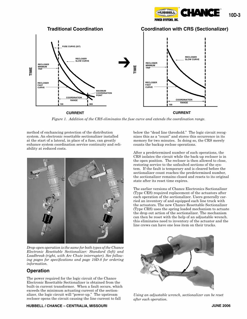
A sectionalizer is a protective device which has no time-current characteristics. With no fuse curve to intersect recloser time-current characteristics, the coordination range is extended to the maximum interrupting rating of the upstream protective device (Figure 1).
This practical function makes the sectionalizer an ideal device for application on single-phase laterals where available fault currents make coordination unachievable with fuses. Electronic resettable sectionalizers provide the utility with an economical and easily retrofittable
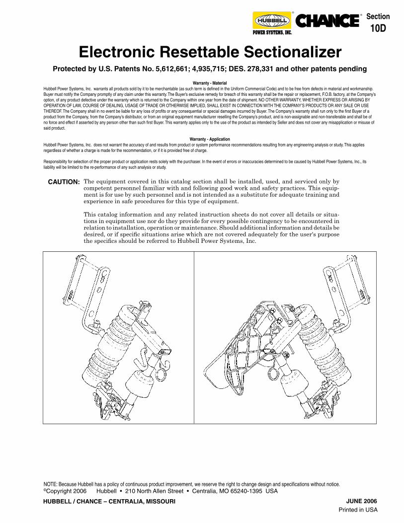
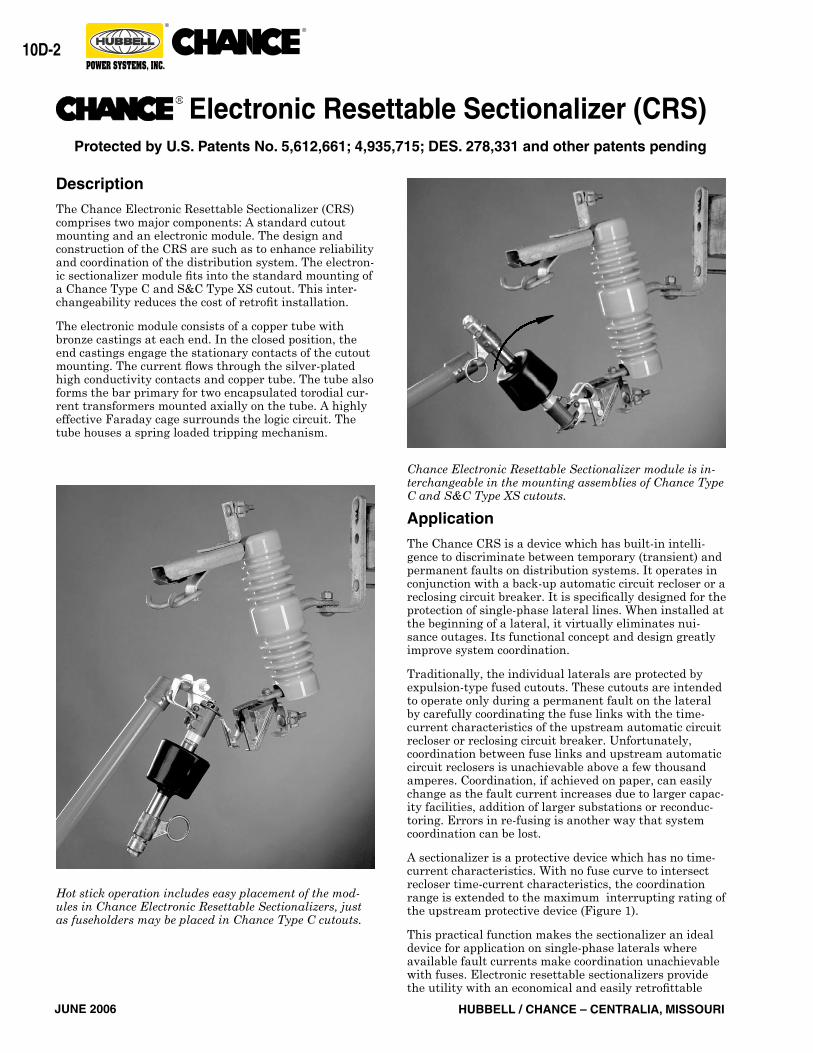
Hot stick operation includes easy placement of the mod-ules in Chance Electronic Resettable Sectionalizers, just as fuseholders may be placed in Chance Type C cutouts.
Chance Electronic Resettable Sectionalizer module is in-terchangeable in the mounting assemblies of Chance Type C and S&C Type XS cutouts.
Electronic Resettable Sectionalizer (CRS)
Description
The Chance Electronic Resettable Sectionalizer (CRS) comprises two major components: A standard cutout mounting and an electronic module. The design and construction of the CRS are such as to enhance reliability and coordination of the distribution system. The electron-ic sectionalizer module fits into the standard mounting of a Chance Type C and S&C Type XS cutout. This inter-changeability reduces the cost of retrofit installation.
The electronic module consists of a copper tube with bronze castings at each end. In the closed position, the end castings engage the stationary contacts of the cutout mounting. The current flows through the silver-plated high conductivity contacts and copper tube. The tube also forms the bar primary for two encapsulated torodial cur-rent transformers mounted axially on the tube. A highly effective Faraday cage surrounds the logic circuit. The tube houses a spring loaded tripping mechanism.
Protected by U.S. Patents No. 5,612,661; 4,935,715; DES. 278,331 and other patents pending
JUNE 2006HUBBELL / CHANCE – CENTRALIA, MISSOURI
10D-�
®®
POWER SYSTEMS, INC.
CURRENT CURRENT
Coordination with CRS (Sectionalizer)Traditional CoordinationT
IME ➔
Figure 1. Addition of the CRS eliminates the fuse curve and extends the coordination range.
method of enchancing protection of the distribution system. An electronic resettable sectionalizer installed at the start of a lateral, in place of a fuse, can greatly enhance system coordination service continuity and reli-ability at reduced costs.
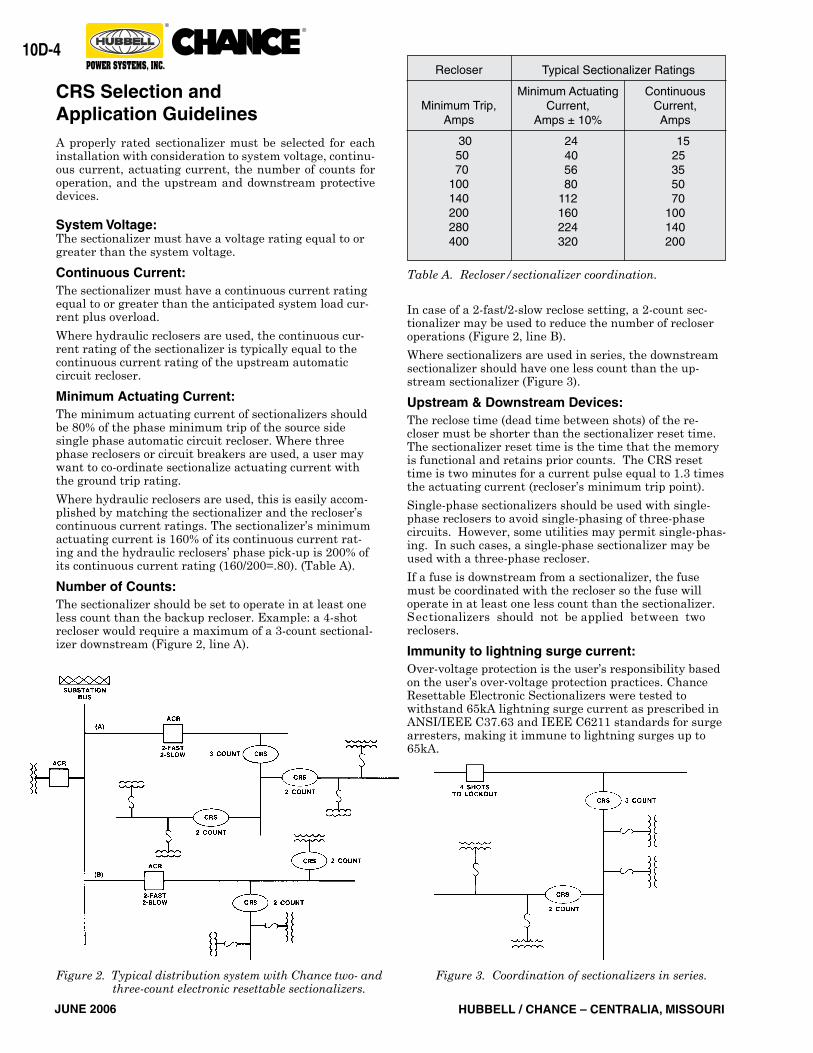
Drop-open operation is the same for both types of the Chance Electronic Resettable Sectionalizer: Standard (left) and Loadbreak (right, with Arc Chute interrupter). See follow-ing pages for specifications and page 10D-8 for ordering information.
Operation
The power required for the logic circuit of the Chance Electronic Resettable Sectionalizer is obtained from the built-in current transformer. When a fault occurs, which exceeds the minimum actuating current of the section-alizer, the logic circuit will “power-up.” The upstream recloser opens the circuit causing the line current to fall
below the “dead line threshold.” The logic circuit recog-nizes this as a “count” and stores this occurrence in its memory for two minutes. In doing so, the CRS merely counts the backup reclose operations.
After a predetermined number of such operations, the CRS isolates the circuit while the back-up recloser is in the open position. The recloser is then allowed to close, restoring service to the unfaulted sections of the sys-tem. If the fault is temporary and is cleared before the sectionalizer count reaches the predetermined number, the sectionalizer remains closed and resets to its original state after its reset time expires.
The earlier versions of Chance Electronics Sectionalizer (Type CES) required replacement of the actuators after each operation of the sectionalizer. Users generally car-ried an inventory of and equipped each line truck with the actuators. The new Chance Resettable Sectionalizer (Type CRS) uses the spring loaded mechanism to actuate the drop out action of the sectionalizer. The mechanism can then be reset with the help of an adjustable wrench. this eliminates need to inventory of the actuator and the line crews can have one less item on their trucks.
TIM
E
FUSE CURVE (25T)
RECLOSERMINIMUMTRIP
RECLOSERFASTCURVE
COORDINATIONRANGE
TIM
E
CURRENT
100 800
MAXIMUMCOORDINATIONPOINT
RECLOSERSLOW CURVE
RECLOSERMINIMUMTRIP
RECLOSERFASTCURVE
TIM
E
CURRENT
100
RECLOSERSLOW CURVE
COORDINATIONRANGE
Using an adjustable wrench, sectionalizer can be reset after each operation.
JUNE 2006 HUBBELL / CHANCE – CENTRALIA, MISSOURI
10D-�
®®
POWER SYSTEMS, INC.
CRS Selection andApplication GuidelinesA properly rated sectionalizer must be selected for each installation with consideration to system voltage, continu-ous current, actuating current, the number of counts for operation, and the upstream and downstream protective devices.
System Voltage:The sectionalizer must have a voltage rating equal to or greater than the system voltage.
Continuous Current:The sectionalizer must have a continuous current rating equal to or greater than the anticipated system load cur-rent plus overload.
Where hydraulic reclosers are used, the continuous cur-rent rating of the sectionalizer is typically equal to the continuous current rating of the upstream automatic circuit recloser.
Minimum Actuating Current:The minimum actuating current of sectionalizers should be 80% of the phase minimum trip of the source side single phase automatic circuit recloser. Where three phase reclosers or circuit breakers are used, a user may want to co-ordinate sectionalize actuating current with the ground trip rating.
Where hydraulic reclosers are used, this is easily accom-plished by matching the sectionalizer and the recloser’s continuous current ratings. The sectionalizer’s minimum actuating current is 160% of its continuous current rat-ing and the hydraulic reclosers’ phase pick-up is 200% of its continuous current rating (160/200=.80). (Table A).
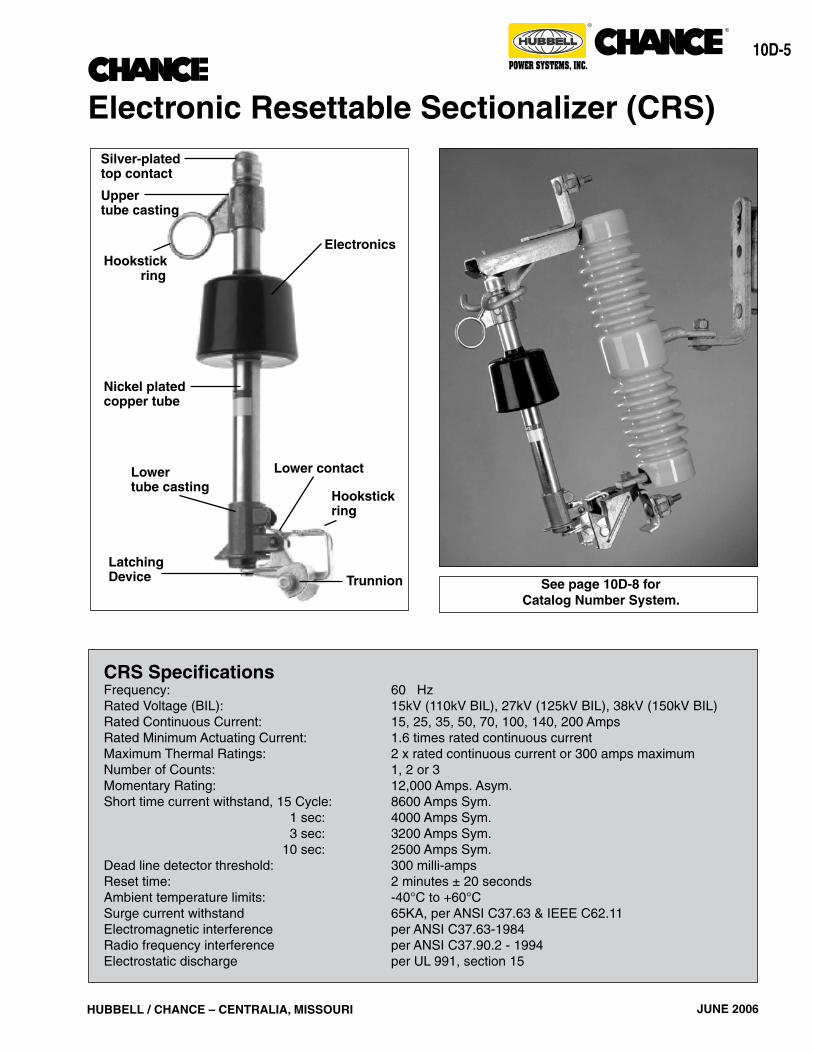
Number of Counts:The sectionalizer should be set to operate in at least one less count than the backup recloser. Example: a 4-shot recloser would require a maximum of a 3-count sectional-izer downstream (Figure 2, line A).
Minimum ActuatingCurrent,
Amps ± 10%
24 40 56 80112160224320
ContinuousCurrent,Amps
15 25 35 50 70100140200
Table A. Recloser/sectionalizer coordination.
Recloser
Minimum Trip,Amps
30 50 70100140200280400
Typical Sectionalizer Ratings
Figure 2. Typical distribution system with Chance two- and three-count electronic resettable sectionalizers.
Figure 3. Coordination of sectionalizers in series.
In case of a 2-fast/2-slow reclose setting, a 2-count sec-tionalizer may be used to reduce the number of recloser operations (Figure 2, line B).
Where sectionalizers are used in series, the downstream sectionalizer should have one less count than the up-stream sectionalizer (Figure 3).
Upstream & Downstream Devices:The reclose time (dead time between shots) of the re-closer must be shorter than the sectionalizer reset time. The sectionalizer reset time is the time that the memory is functional and retains prior counts. The CRS reset time is two minutes for a current pulse equal to 1.3 times the actuating current (recloser’s minimum trip point).
Single-phase sectionalizers should be used with single-phase reclosers to avoid single-phasing of three-phase circuits. However, some utilities may permit single-phas-ing. In such cases, a single-phase sectionalizer may be used with a three-phase recloser.
If a fuse is downstream from a sectionalizer, the fuse must be coordinated with the recloser so the fuse will operate in at least one less count than the sectionalizer.Sectionalizers should not be applied between two reclosers.
Immunity to lightning surge current:Over-voltage protection is the user’s responsibility based on the user’s over-voltage protection practices. Chance Resettable Electronic Sectionalizers were tested to withstand 65kA lightning surge current as prescribed in ANSI/IEEE C37.63 and IEEE C6211 standards for surge arresters, making it immune to lightning surges up to 65kA.
JUNE 2006HUBBELL / CHANCE – CENTRALIA, MISSOURI
10D-�
®®
POWER SYSTEMS, INC.
CRS SpecificationsFrequency: 60 HzRated Voltage (BIL): 15kV (110kV BIL), 27kV (125kV BIL), 38kV (150kV BIL)Rated Continuous Current: 15, 25, 35, 50, 70, 100, 140, 200 AmpsRated Minimum Actuating Current: 1.6 times rated continuous currentMaximum Thermal Ratings: 2 x rated continuous current or 300 amps maximumNumber of Counts: 1, 2 or 3Momentary Rating: 12,000 Amps. Asym.Short time current withstand, 15 Cycle: 8600 Amps Sym. 1 sec: 4000 Amps Sym. 3 sec: 3200 Amps Sym. 10 sec: 2500 Amps Sym.Dead line detector threshold: 300 milli-amps Reset time: 2 minutes ± 20 secondsAmbient temperature limits: -40°C to +60°CSurge current withstand 65KA, per ANSI C37.63 & IEEE C62.11Electromagnetic interference per ANSI C37.63-1984Radio frequency interference per ANSI C37.90.2 - 1994Electrostatic discharge per UL 991, section 15
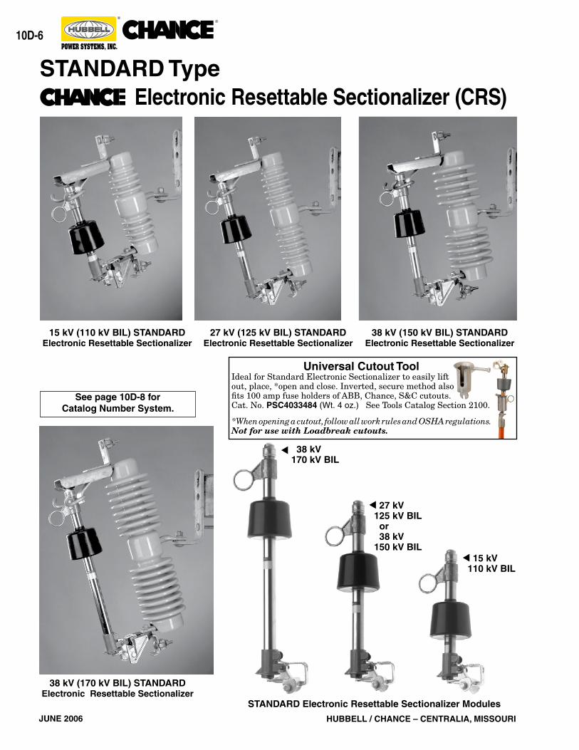
Silver-platedtop contact
Nickel platedcopper tube
Lower contact
LatchingDevice
ElectronicsHookstick ring
Lowertube casting
Upper tube casting
Hookstickring
Trunnion
Electronic Resettable Sectionalizer (CRS)
See page 10D-8 forCatalog Number System.
JUNE 2006 HUBBELL / CHANCE – CENTRALIA, MISSOURI
10D-�
®®
POWER SYSTEMS, INC.
Universal Cutout ToolIdeal for Standard Electronic Sectionalizer to easily liftout, place, *open and close. Inverted, secure method alsofits 100 amp fuse holders of ABB, Chance, S&C cutouts.Cat. No. PSC4033484 (Wt. 4 oz.) See Tools Catalog Section 2100. *When opening a cutout, follow all work rules and OSHA regulations. Not for use with Loadbreak cutouts.
STANDARD Type Electronic Resettable Sectionalizer (CRS)
38 kV (150 kV BIL) STANDARDElectronic Resettable Sectionalizer
15 kV (110 kV BIL) STANDARDElectronic Resettable Sectionalizer
27 kV (125 kV BIL) STANDARDElectronic Resettable Sectionalizer
38 kV 170 kV BIL
▲
15 kV 110 kV BIL
▲
27 kV 125 kV BIL or 38 kV 150 kV BIL
▲
STANDARD Electronic Resettable Sectionalizer Modules
38 kV (170 kV BIL) STANDARDElectronic Resettable Sectionalizer
See page 10D-8 forCatalog Number System.
JUNE 2006HUBBELL / CHANCE – CENTRALIA, MISSOURI
10D-�
®®
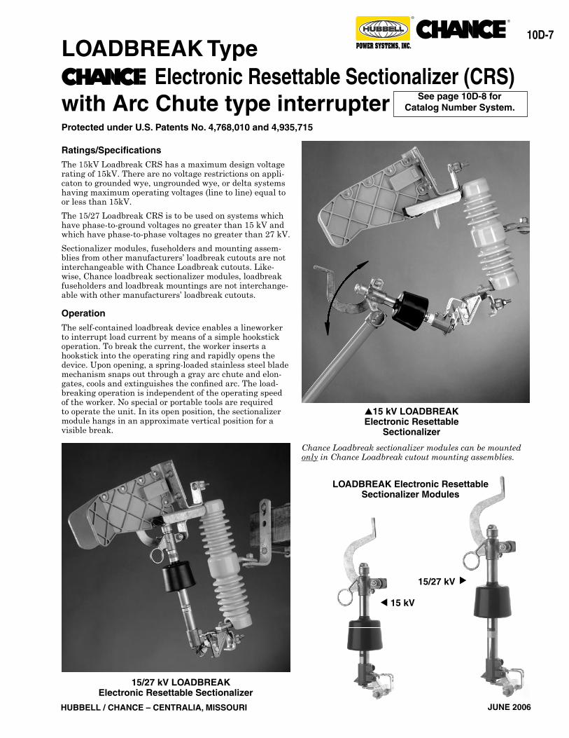
POWER SYSTEMS, INC.LOADBREAK Type Electronic Resettable Sectionalizer (CRS) with Arc Chute type interrupter See page 10D-8 for
Catalog Number System.
Ratings/Specifications
The 15kV Loadbreak CRS has a maximum design voltage rating of 15kV. There are no voltage restrictions on appli-caton to grounded wye, ungrounded wye, or delta systems having maximum operating voltages (line to line) equal to or less than 15kV.
The 15/27 Loadbreak CRS is to be used on systems which have phase-to-ground voltages no greater than 15 kV and which have phase-to-phase voltages no greater than 27 kV.
Sectionalizer modules, fuseholders and mounting assem-blies from other manufacturers’ loadbreak cutouts are not interchangeable with Chance Loadbreak cutouts. Like-wise, Chance loadbreak sectionalizer modules, loadbreak fuseholders and loadbreak mountings are not interchange-able with other manufacturers’ loadbreak cutouts.
Operation
The self-contained loadbreak device enables a lineworker to interrupt load current by means of a simple hookstick operation. To break the current, the worker inserts a hookstick into the operating ring and rapidly opens the device. Upon opening, a spring-loaded stainless steel blade mechanism snaps out through a gray arc chute and elon-gates, cools and extinguishes the confined arc. The load-breaking operation is independent of the operating speed of the worker. No special or portable tools are required to operate the unit. In its open position, the sectionalizer module hangs in an approximate vertical position for a visible break.
15/27 kV LOADBREAKElectronic Resettable Sectionalizer
15 kV▲
▲15 kV LOADBREAKElectronic Resettable
Sectionalizer
▲
15/27 kV
LOADBREAK Electronic Resettable Sectionalizer Modules
Chance Loadbreak sectionalizer modules can be mounted only in Chance Loadbreak cutout mounting assemblies.
Protected under U.S. Patents No. 4,768,010 and 4,935,715
JUNE 2006 HUBBELL / CHANCE – CENTRALIA, MISSOURI
10D-�
®®
POWER SYSTEMS, INC.
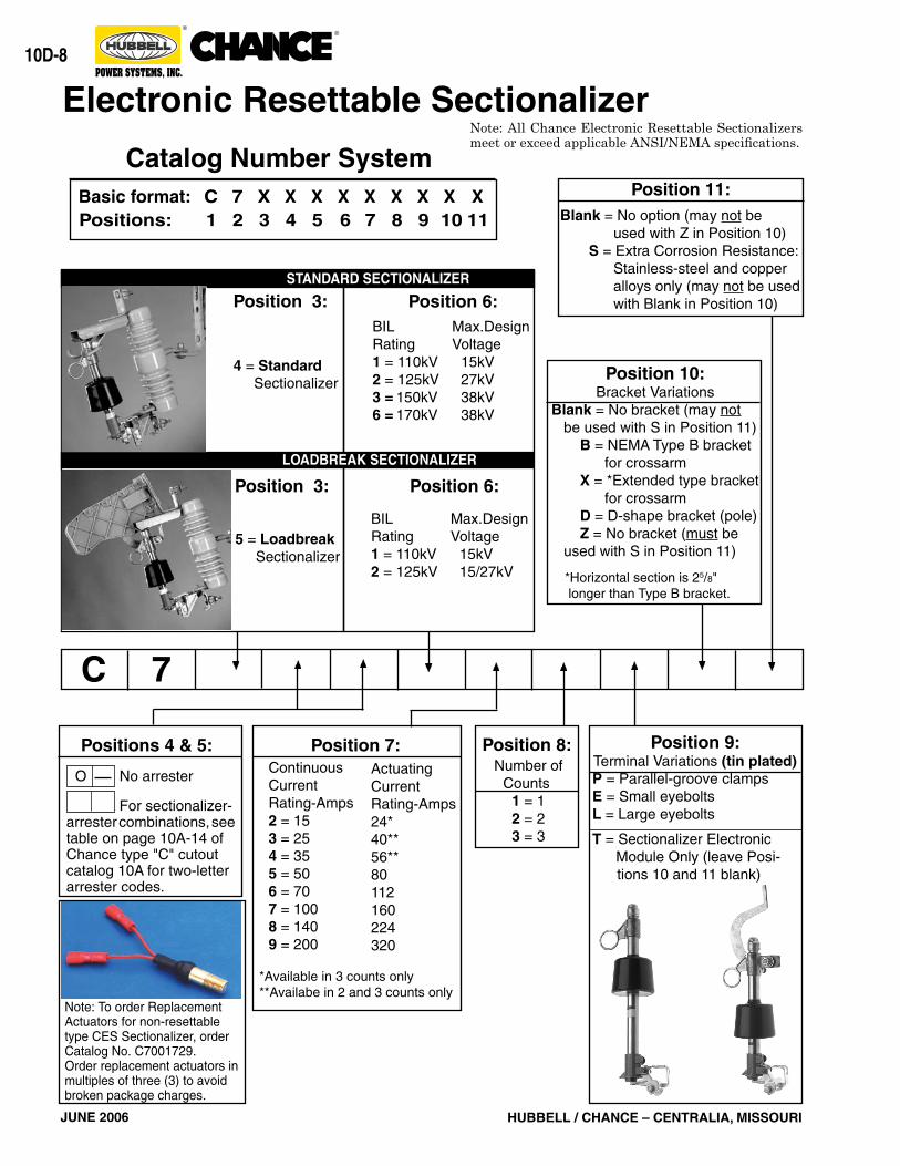
Continuous Current Rating-Amps2 = 153 = 254 = 355 = 506 = 707 = 1008 = 1409 = 200
ActuatingCurrentRating-Amps24*40**56**80112160224320
For sectionalizer-arrester combinations, see table on page 10A-14 of Chance type "C" cutout catalog 10A for two-letter arrester codes.
7
Number ofCounts 1 = 1 2 = 2 3 = 3
Position 8:Position 7:
O No arrester
Positions 4 & 5:
C
4 = Standard Sectionalizer
Position 3: Position 6:BIL Max.DesignRating Voltage1 = 110kV 15kV2 = 125kV 27kV3 = 150kV 38kV6 = 170kV 38kV
5 = Loadbreak Sectionalizer
BIL Max.DesignRating Voltage1 = 110kV 15kV2 = 125kV 15/27kV
Position 3: Position 6:
STANDARD SECTIONALIZER
LOADBREAK SECTIONALIZER
Electronic Resettable Sectionalizer
Basic format: C 7 X X X X X X X X XPositions: 1 2 3 4 5 6 7 8 9 10 11
Note: All Chance Electronic Resettable Sectionalizers meet or exceed applicable ANSI/NEMA specifications.
Position 10:Bracket Variations
Blank = No bracket (may not be used with S in Position 11) B = NEMA Type B bracket for crossarm X = *Extended type bracket for crossarm D = D-shape bracket (pole) Z = No bracket (must be used with S in Position 11)
*Horizontal section is 25/8" longer than Type B bracket.
Position 11:Blank = No option (may not be used with Z in Position 10) S = Extra Corrosion Resistance: Stainless-steel and copper alloys only (may not be used with Blank in Position 10)
Position 9:Terminal Variations (tin plated)P = Parallel-groove clampsE = Small eyeboltsL = Large eyebolts T = Sectionalizer Electronic Module Only (leave Posi- tions 10 and 11 blank)
Note: To order Replacement Actuators for non-resettable type CES Sectionalizer, order Catalog No. C7001729.Order replacement actuators in multiples of three (3) to avoid broken package charges.
Catalog Number System
*Available in 3 counts only**Availabe in 2 and 3 counts only