Embed Size (px)
Citation preview
10A-1
HUBBELL / CHANCE – CENTRALIA, MISSOURI FEBRUARY 1998
®®
POWER SYSTEMS, INC.
Printed in USA
Section
10A
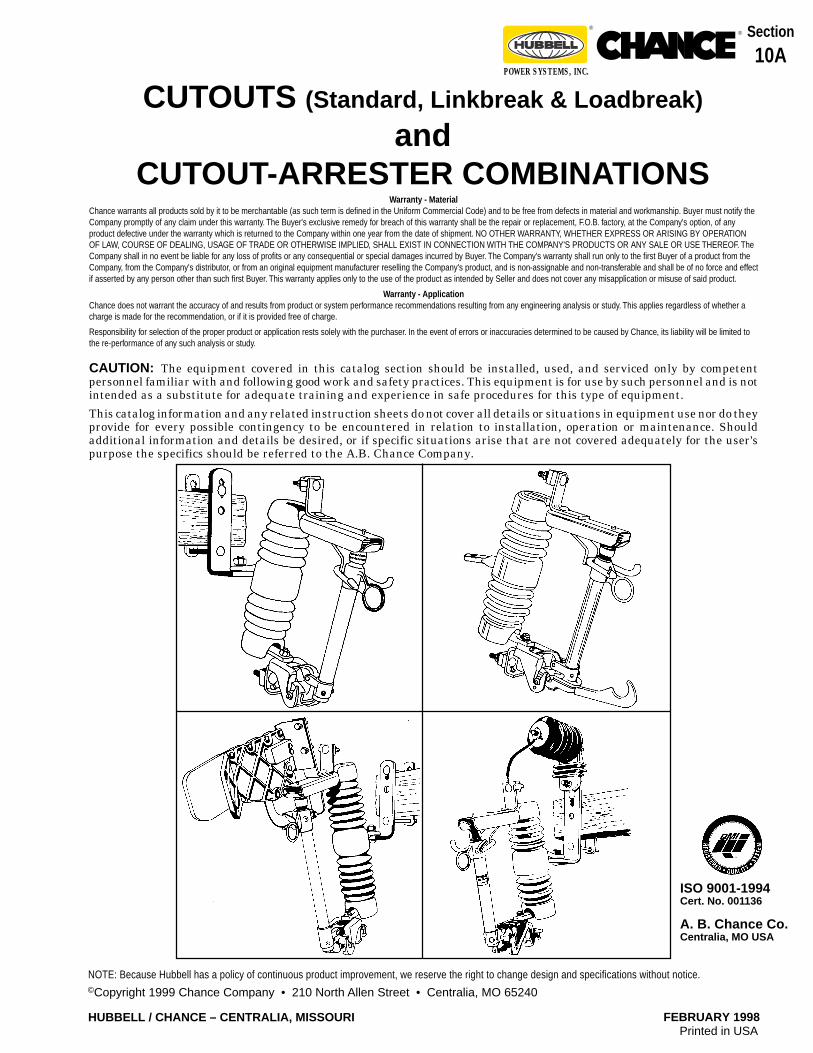
CUTOUTS (Standard, Linkbreak & Loadbreak)
andCUTOUT-ARRESTER COMBINATIONS
CAUTION: The equipment covered in this catalog section should be installed, used, and serviced only by competentpersonnel familiar with and following good work and safety practices. This equipment is for use by such personnel and is notintended as a substitute for adequate training and experience in safe procedures for this type of equipment.
This catalog information and any related instruction sheets do not cover all details or situations in equipment use nor do theyprovide for every possible contingency to be encountered in relation to installation, operation or maintenance. Shouldadditional information and details be desired, or if specific situations arise that are not covered adequately for the user'spurpose the specifics should be referred to the A.B. Chance Company.
Warranty - MaterialChance warrants all products sold by it to be merchantable (as such term is defined in the Uniform Commercial Code) and to be free from defects in material and workmanship. Buyer must notify theCompany promptly of any claim under this warranty. The Buyer's exclusive remedy for breach of this warranty shall be the repair or replacement, F.O.B. factory, at the Company's option, of anyproduct defective under the warranty which is returned to the Company within one year from the date of shipment. NO OTHER WARRANTY, WHETHER EXPRESS OR ARISING BY OPERATIONOF LAW, COURSE OF DEALING, USAGE OF TRADE OR OTHERWISE IMPLIED, SHALL EXIST IN CONNECTION WITH THE COMPANY'S PRODUCTS OR ANY SALE OR USE THEREOF. TheCompany shall in no event be liable for any loss of profits or any consequential or special damages incurred by Buyer. The Company's warranty shall run only to the first Buyer of a product from theCompany, from the Company's distributor, or from an original equipment manufacturer reselling the Company's product, and is non-assignable and non-transferable and shall be of no force and effectif asserted by any person other than such first Buyer. This warranty applies only to the use of the product as intended by Seller and does not cover any misapplication or misuse of said product.
Warranty - ApplicationChance does not warrant the accuracy of and results from product or system performance recommendations resulting from any engineering analysis or study. This applies regardless of whether acharge is made for the recommendation, or if it is provided free of charge.
Responsibility for selection of the proper product or application rests solely with the purchaser. In the event of errors or inaccuracies determined to be caused by Chance, its liability will be limited tothe re-performance of any such analysis or study.
ISO 9001-1994Cert. No. 001136
A. B. Chance Co.Centralia, MO USA
©Copyright 1999 Chance Company • 210 North Allen Street • Centralia, MO 65240
NOTE: Because Hubbell has a policy of continuous product improvement, we reserve the right to change design and specifications without notice.
10A-2
FEBRUARY 1998 HUBBELL / CHANCE – CENTRALIA, MISSOURI
®®
POWER SYSTEMS, INC.
Patent Nos. DES.278,331; 4,546,341
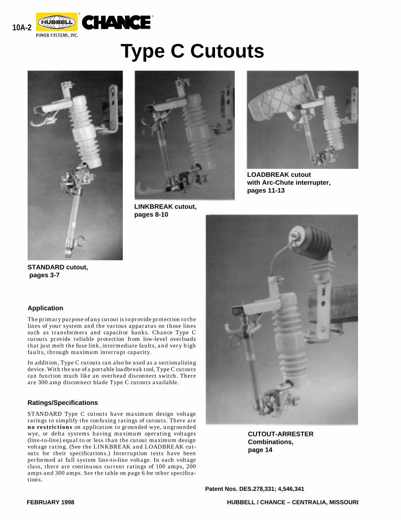
Type C Cutouts
LOADBREAK cutoutwith Arc-Chute interrupter,pages 11-13
STANDARD cutout, pages 3-7
LINKBREAK cutout,pages 8-10
CUTOUT-ARRESTERCombinations,page 14
Application
The primary purpose of any cutout is to provide protection to thelines of your system and the various apparatus on those linessuch as transformers and capacitor banks. Chance Type Ccutouts provide reliable protection from low-level overloadsthat just melt the fuse link, intermediate faults, and very highfaults, through maximum interrupt capacity.
In addition, Type C cutouts can also be used as a sectionalizingdevice. With the use of a portable loadbreak tool, Type C cutoutscan function much like an overhead disconnect switch. Thereare 300 amp disconnect blade Type C cutouts available.
Ratings/Specifications
STANDARD Type C cutouts have maximum design voltageratings to simplify the confusing ratings of cutouts. There areno restrictions on application to grounded wye, ungroundedwye, or delta systems having maximum operating voltages(line-to-line) equal to or less than the cutout maximum designvoltage rating. (See the LINKBREAK and LOADBREAK cut-outs for their specifications.) Interruption tests have beenperformed at full system line-to-line voltage. In each voltageclass, there are continuous current ratings of 100 amps, 200amps and 300 amps. See the table on page 6 for other specifica-tions.
10A-3
HUBBELL / CHANCE – CENTRALIA, MISSOURI FEBRUARY 1998
®®
POWER SYSTEMS, INC.
Insulators
The insulators used on Type C cutouts are a sky-glaze gray.The metal to metal leakage distance on the 15 kV cutoutinsulator is 8.7 inches (220 mm), 12.6 inches (320 mm) on the27 kV (125 kV BIL), 17.3 inches (440 mm) on the 27 kV (150kV BIL), 26 inches (660 mm) on the 27 kV (170 kV BIL), and28.4 inches (720 mm) on the 27 kV (170 kV BIL) .
Fuseholders
The solid cap on the single vent fuseholder is a copper alloy,silver-plated to provide efficient current transfer. An integralring is provided in the top tube casting for opening andclosing the fuseholder with conventional disconnect toolsfrom the ground, from a bucket truck or from the pole.
The toggle type trunnion casting is a selective silver-plated bronze for efficient current transfer to the lowerhinge contacts. A cam shaped projection on each side of thetrunnion casting provides high pressure parallel currentpaths to the lower contacts. These projections, or pivot pins,are cast full round for smooth rotational operation in thehinge. The link ejector assists in arc interruption during lowfault current or excessive overload conditions. A groove in thecenter of the link ejector allows the fuse link’s pigtail to godirectly from the fuse tube to the attachment nut. A curvedejector minimizes bending stresses in the pigtail to preventbroken strands. A stainless steel torsion spring on the linkejector helps to rapidly eject the link from the bore of thefuseholder during interruption. The 200 amp link ejector hasa wider groove area and increased spring force to accommo-date the larger links.
The link ejector is pinned to the trunnion casting with astainless steel pin to provide resistance to corrosive elementsand assure smooth pivotal action. An interlocking featurebetween the link ejector and tube casting prevents excessivetension on the fuse link during closure, thereby preventinglink breakage.
The link ejector employs a hammer effect to insure toggleaction of the trunnion during low fault and overload interrup-tions, hence dropout action is assured. The link ejectorprovides sufficient surface area to facilitate re-fusing bylinemen wearing gloves.
Quality Construction
Efficient Current Transfer
The Chance Type C cutout has an all copper current path. Allcontacts are silver-plated. Terminals are tin-plated bronzefor use with copper or aluminum conductors.
Loadbreak Hooks
Galvanized steel hooks are standard on all Type C cutouts,except the arc chute version, for use with a portable loadbreaktool. These sturdy hooks are mounted on the top support andserve to guide the fuseholder into the latch socket whenclosing at an off-center angle.
Top Contact
The top contact is attached to the galvanized-steel hood by astainless rivet to provide a smooth self-aligning action duringclosing even in severely corrosive environments. The topcontact provides a socket-type cavity for latching the fuse-holder and prevents any possible “over-travel” of the fuse-holder. The top contact is made of a highly conductive copperstrip with silver-plated embossments to resist corrosion. Thecontacts are held under constant pressure designed to main-tain firm contact with the fuseholder contact surface untilfault interruption is accomplished.
Hinge
The hinge on the Type C cutout employs large pivot areas forthe fuseholder’s trunnion and is cast of a copper alloy chosenfor its strength and corrosion resistance. The hinge contactsare highly conductive copper alloy stampings and are platedto assure low resistance current transfer from the trunnioncasting. The parallel current paths are backed up by highstrength cantilever springs and are riveted to the hingecastings. Fuseholder can be dropped into place and easilylifted up and out. No tricky maneuvering.
Type C STANDARD Cutout
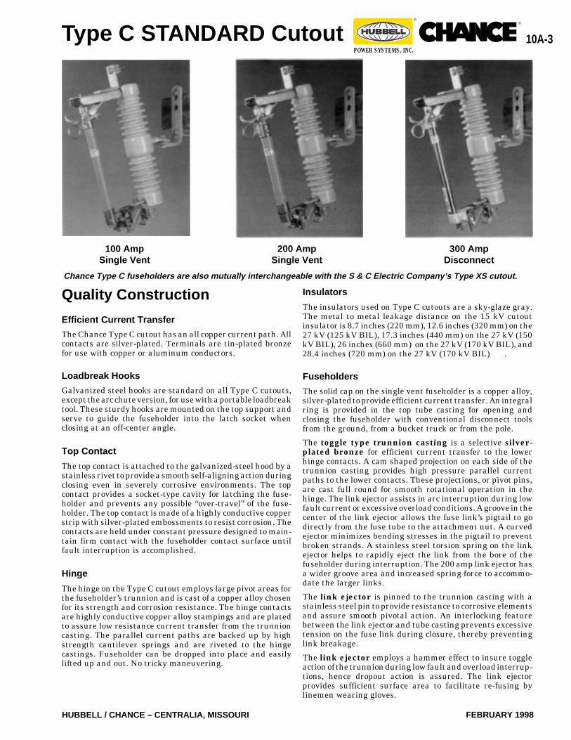
Chance Type C fuseholders are also mutually interchangeable with the S & C Electric Company’s Type XS cutout.
100 AmpSingle Vent
200 AmpSingle Vent
300 AmpDisconnect
10A-4
FEBRUARY 1998 HUBBELL / CHANCE – CENTRALIA, MISSOURI
®®
POWER SYSTEMS, INC.
Type C STANDARD Cutout
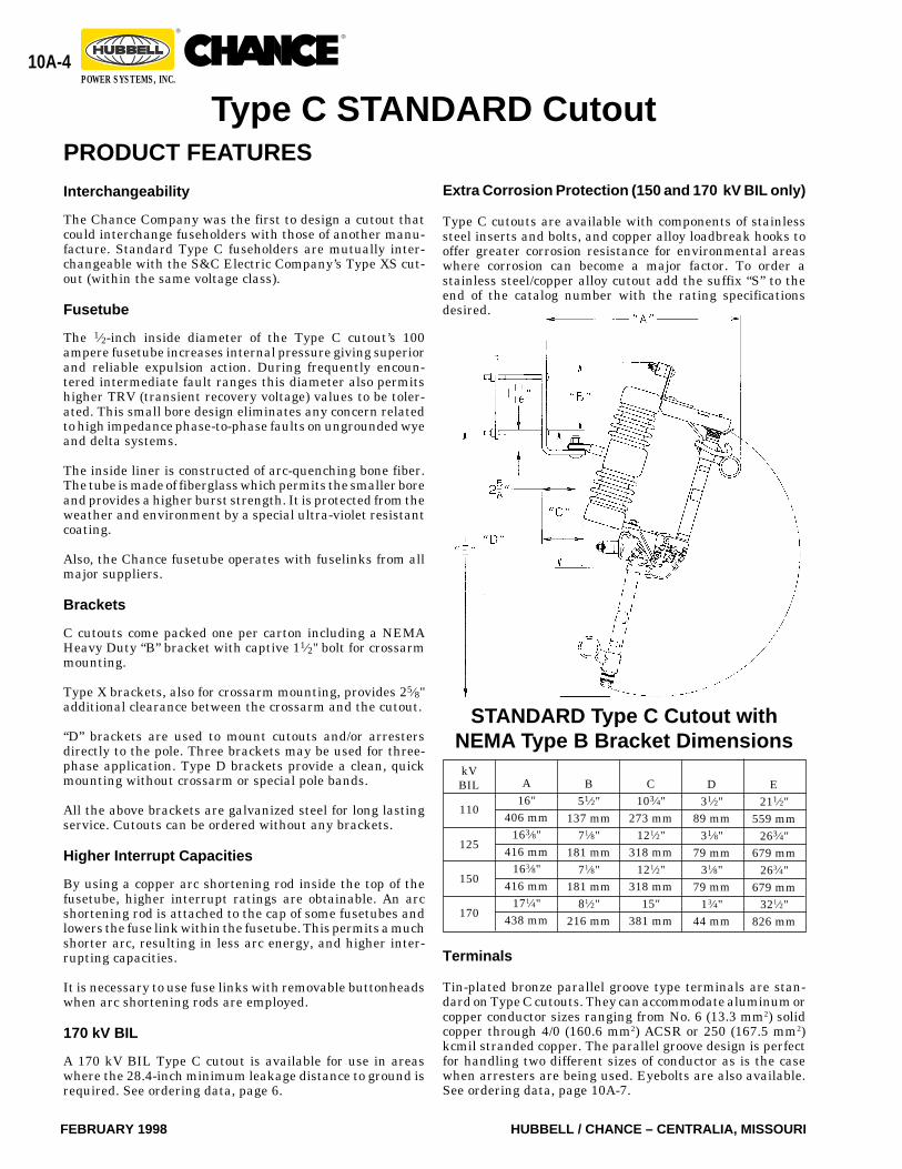
kVBIL
110
125
150
170
STANDARD Type C Cutout withNEMA Type B Bracket Dimensions
A16"
406 mm163⁄8"
416 mm163⁄8"
416 mm171⁄4"
438 mm
B51⁄2"
137 mm71⁄8"
181 mm71⁄8"
181 mm81⁄2"
216 mm
C103⁄4"
273 mm121⁄2"
318 mm121⁄2"
318 mm15"
381 mm
D31⁄2"
89 mm31⁄8"
79 mm31⁄8"
79 mm13⁄4"
44 mm
E211⁄2"
559 mm263⁄4"
679 mm263⁄4"
679 mm321⁄2"
826 mm
PRODUCT FEATURES
Interchangeability
The Chance Company was the first to design a cutout thatcould interchange fuseholders with those of another manu-facture. Standard Type C fuseholders are mutually inter-changeable with the S&C Electric Company’s Type XS cut-out (within the same voltage class).
Fusetube
The 1⁄2-inch inside diameter of the Type C cutout’s 100ampere fusetube increases internal pressure giving superiorand reliable expulsion action. During frequently encoun-tered intermediate fault ranges this diameter also permitshigher TRV (transient recovery voltage) values to be toler-ated. This small bore design eliminates any concern relatedto high impedance phase-to-phase faults on ungrounded wyeand delta systems.
The inside liner is constructed of arc-quenching bone fiber.The tube is made of fiberglass which permits the smaller boreand provides a higher burst strength. It is protected from theweather and environment by a special ultra-violet resistantcoating.
Also, the Chance fusetube operates with fuselinks from allmajor suppliers.
Brackets
C cutouts come packed one per carton including a NEMAHeavy Duty “B” bracket with captive 11⁄2" bolt for crossarmmounting.
Type X brackets, also for crossarm mounting, provides 25⁄8"additional clearance between the crossarm and the cutout.
“D” brackets are used to mount cutouts and/or arrestersdirectly to the pole. Three brackets may be used for three-phase application. Type D brackets provide a clean, quickmounting without crossarm or special pole bands.
All the above brackets are galvanized steel for long lastingservice. Cutouts can be ordered without any brackets.
Higher Interrupt Capacities
By using a copper arc shortening rod inside the top of thefusetube, higher interrupt ratings are obtainable. An arcshortening rod is attached to the cap of some fusetubes andlowers the fuse link within the fusetube. This permits a muchshorter arc, resulting in less arc energy, and higher inter-rupting capacities.
It is necessary to use fuse links with removable buttonheadswhen arc shortening rods are employed.
170 kV BIL
A 170 kV BIL Type C cutout is available for use in areaswhere the 28.4-inch minimum leakage distance to ground isrequired. See ordering data, page 6.
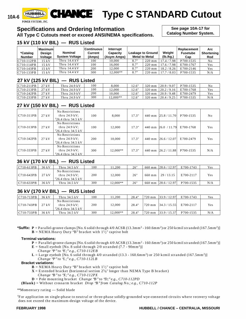
Extra Corrosion Protection (150 and 170 kV BIL only)
Type C cutouts are available with components of stainlesssteel inserts and bolts, and copper alloy loadbreak hooks tooffer greater corrosion resistance for environmental areaswhere corrosion can become a major factor. To order astainless steel/copper alloy cutout add the suffix “S” to theend of the catalog number with the rating specificationsdesired.
Terminals
Tin-plated bronze parallel groove type terminals are stan-dard on Type C cutouts. They can accommodate aluminum orcopper conductor sizes ranging from No. 6 (13.3 mm2) solidcopper through 4/0 (160.6 mm2) ACSR or 250 (167.5 mm2)kcmil stranded copper. The parallel groove design is perfectfor handling two different sizes of conductor as is the casewhen arresters are being used. Eyebolts are also available.See ordering data, page 10A-7.
10A-5
HUBBELL / CHANCE – CENTRALIA, MISSOURI FEBRUARY 1998
®®
POWER SYSTEMS, INC.
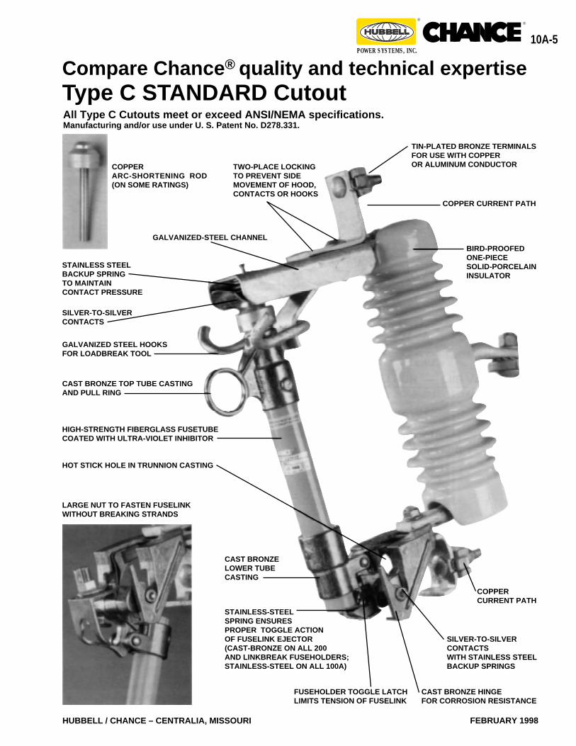
STAINLESS-STEELSPRING ENSURESPROPER TOGGLE ACTIONOF FUSELINK EJECTOR(CAST-BRONZE ON ALL 200AND LINKBREAK FUSEHOLDERS;STAINLESS-STEEL ON ALL 100A)
Compare Chance ® quality and technical expertise
SILVER-TO-SILVERCONTACTS
CAST BRONZE HINGEFOR CORROSION RESISTANCE
COPPERCURRENT PATH
FUSEHOLDER TOGGLE LATCHLIMITS TENSION OF FUSELINK
SILVER-TO-SILVERCONTACTSWITH STAINLESS STEELBACKUP SPRINGS
CAST BRONZELOWER TUBECASTING
CAST BRONZE TOP TUBE CASTINGAND PULL RING
HIGH-STRENGTH FIBERGLASS FUSETUBECOATED WITH ULTRA-VIOLET INHIBITOR
GALVANIZED STEEL HOOKSFOR LOADBREAK TOOL
STAINLESS STEELBACKUP SPRINGTO MAINTAINCONTACT PRESSURE
BIRD-PROOFEDONE-PIECESOLID-PORCELAININSULATOR
TIN-PLATED BRONZE TERMINALSFOR USE WITH COPPEROR ALUMINUM CONDUCTOR
GALVANIZED-STEEL CHANNEL
COPPERARC-SHORTENING ROD(ON SOME RATINGS)
TWO-PLACE LOCKINGTO PREVENT SIDEMOVEMENT OF HOOD,CONTACTS OR HOOKS
LARGE NUT TO FASTEN FUSELINKWITHOUT BREAKING STRANDS
HOT STICK HOLE IN TRUNNION CASTING
COPPER CURRENT PATH
Type C STANDARD CutoutAll Type C Cutouts meet or exceed ANSI/NEMA specifications.Manufacturing and/or use under U. S. Patent No. D278.331.
10A-6
FEBRUARY 1998 HUBBELL / CHANCE – CENTRALIA, MISSOURI
®®
POWER SYSTEMS, INC.
P700-1535
E700-1768
E700-2479
P700-1535
320 mm320 mm320 mm320 mm
P700-1535E700-1768E700-2479P700-1535
*Suffix: P = Parallel-groove clamps [No. 6 solid through 4/0 ACSR (13.3mm2 - 160.6mm2) or 250 kcmil stranded (167.5mm2)]B = NEMA Heavy Duty “B” bracket with 11⁄2" captive bolt
Terminal variations:P = Parallel-groove clamps [No. 6 solid through 4/0 ACSR (13.3mm2 - 160.6mm2) or 250 kcmil stranded (167.5mm2)]E = Small eyebolt [No. 8 solid through 2/0 stranded (7.7 - 90mm2)]
Change “P” to “E;” e.g., C710-112EBL = Large eyebolt [No. 6 solid through 4/0 stranded (13.3 - 160.6mm2) or 250 kcmil stranded (167.5mm2)]
Change “P” to “L;” e.g., C710-112LBBracket variations:
B = NEMA Heavy Duty “B” bracket with 11⁄2" captive boltX = Extended bracket (horizontal section 25⁄8" longer than NEMA Type B bracket)
Change “B” to “X;” e.g., C710-112PXD = Pole mounting bracket Change “B” to “D;” e.g., C710-112PD
(Blank) = Without crossarm bracket Drop “B” from Catalog No.; e.g., C710-112P
**Momentary rating — Solid blade
†For application on single-phase to neutral or three-phase solidly-grounded wye-connected circuits where recovery voltagedoes not exceed the maximum-design voltage of the device.
Type C STANDARD Cutout
MaximumDesignVoltage15 kV15 kV15 kV15 kV
*CatalogNumber
C710-112PBC710-114PBC710-143PBC710-133PB
NominalSystem Voltage
Thru 14.4 kVThru 14.4 kVThru 14.4 kVThru 14.4 kV
220 mm220 mm220 mm220 mm
ArcShortening
RodNoYesYesN/A
ContinuousCurrent(Amps)
100100200300
8.7"8.7"8.7"8.7"
Leakage to GroundMetal to Metal
InterruptCapacity
(Asym Amps)10,00016,00012,00012,000**
27 kV (125 kV BIL) — RUS Listed27 kV27 kV27 kV27 kV
NoYesYesN/A
100100200300
8,00012,00010,00012,000**
Thru 24.9 kVThru 24.9 kVThru 24.9 kVThru 24.9 kV
C710-211PBC710-213PBC710-242PBC710-233PB
12.6"12.6"12.6"12.6"
27 kV (150 kV BIL) — RUS ListedNo Restrictionsthru 24.9 kV;
†26.4 thru 34.5 kVNo Restrictionsthru 24.9 kV;
†26.4 thru 34.5 kVNo Restrictionsthru 24.9 kV;
†26.4 thru 34.5 kVNo Restrictionsthru 24.9 kV;
†26.4 thru 34.5 kV
440 mm
440 mm
440 mm
440 mm
660 mm
660 mm
660 mm
26"
26"
26"
36 kV
27 kV
36 kV
Yes
Yes
N/A
100
200
300
11,200
12,000
12,000**
36 kV (170 kV BIL) — RUS ListedC710-613PB
C710-643PB
C710-633PB
720 mm
720 mm
720 mm
28.4"
28.4"
28.4"
36 kV
27 kV
36 kV
Yes
Yes
N/A
100
200
300
11,200
12,000
12,000**
36 kV (170 kV BIL) — RUS ListedC710-713PB
C710-743PB
C710-733PB
Thru 34.5 kVNo Restrictionsthru 24.9 kV;
†26.4 thru 34.5 kVThru 34.5 kV
Specifications and Ordering InformationAll Type C Cutouts meet or exceed ANSI/NEMA specifications.
15 kV (110 kV BIL) — RUS Listed
See page 10A-17 forCatalog Number System.
Thru 34.5 kVNo Restrictionsthru 24.9 kV;
†26.4 thru 34.5 kVThru 34.5 kV
No
Yes
Yes
N/A
C710-311PB
C710-313PB
C710-342PB
C710-333PB
27 kV
27 kV
27 kV
27 kV
100
100
200
300
8,000
12,000
10,000
12,000**
17.3"
17.3"
17.3"
17.3"
25.8 / 11.70
26.0 / 11.79
26.6 / 12.07
26.2 / 11.88
Weight(lb./kg.)
17.4 / 7.9817.6 / 7.9818.2 / 8.2617.7 / 8.03
ReplacementFusetube
CapP700-1535E700-1767E700-2146P700-1535
20.9 / 9.0720.2 / 9.1620.9 / 9.4820.4 / 9.25
E700-1743
E700-2117
P700-1535
E700-1743
E700-2117
P700-1535
28.6 / 12.97
29 / 13.15
28.6 / 12.97
33.9 / 12.97
34.3 / 15.55
33.9 / 15.37
10A-7
HUBBELL / CHANCE – CENTRALIA, MISSOURI FEBRUARY 1998
®®
POWER SYSTEMS, INC.
*Suffix: P = Parallel-groove clamps [No. 6 solid through 4/0 ACSR (13.3mm2 - 160.6mm2) or 250 kcmil stranded (167.5mm2)]B = NEMA Heavy Duty “B” bracket with 11⁄2" captive bolt
Terminal variations:P = Parallel-groove clamps [No. 6 solid through 4/0 ACSR (13.3mm2 - 160.6mm2) or 250 kcmil stranded (167.5mm2)]E = Small eyebolt [No. 8 solid through 2/0 stranded (7.7 - 90mm2)]
Change “P” to “E;” e.g., C710-1MMEBL = Large eyebolt [No. 6 solid through 4/0 stranded (13.3 - 160.6mm2) or 250 kcmil stranded (167.5mm2)]
Change “P” to “L;” e.g., C710-1MMLBBracket variations:
B = NEMA Heavy Duty “B” bracket with 11⁄2" captive boltX = Extended bracket (horizontal section 25⁄8" longer than NEMA Type B bracket)
Change “B” to “X;” e.g., C710-1MMPXD = Pole mounting bracket Change “B” to “D;” e.g., C710-1MMPD
(Blank) = Without crossarm bracket Drop “B” from Catalog No.;” e.g., C710-1MMP
Type C STANDARD Cutout
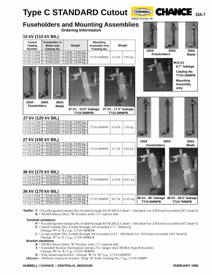
1.8 lb.2.0 lb.2.6 lb.2.1 lb.
CutoutCatalogNumber
C710-112PBC710-114PBC710-143PBC710-133PB
Fuseholders and Mounting AssembliesOrdering Information
0.82 kg.0.91 kg.1.18 kg.0.95 kg.
15 kV (110 kV BIL)Mounting
Assembly only*Catalog No.
T710-1MMPB
Fuseholder orBlade onlyCatalog No.T710-112TT710-114TT710-143TT710-133T
5.85 kg.12.9 lb.
Weight Weight
36 kV (170 kV BIL)C710-613PBC710-643PBC710-633PB
T710-613TT710-643TT710-633T
2.8lb.3.2 lb.2.8 lb.
1.27 kg.1.45 kg.1.27 kg.
10.61 kg.23.4 lb.T710-6MMPB
36 kV (170 kV BIL)C710-713PBC710-743PBC710-733PB
T710-713TT710-743TT710-733T
2.8lb.3.2 lb.2.8 lb.
1.27 kg.1.45 kg.1.27 kg.
13.02 kg.28.7 lb.T710-7MMPB
C710-211PBC710-213PBC710-242PBC710-233PB
27 kV (150 kV BIL)
T710-211TT710-213TT710-242TT710-233T
2.1 lb.2.3 lb.2.7 lb.2.5 lb.
0.95 kg.1.14 kg.1.22 kg.1.13 kg.
7.08 kg.15.6 lb.T710-2MMPB
C710-311PBC710-313PBC710-342PBC710-333PB
T710-311TT710-313TT710-342TT710-333T
2.1 lb.2.3 lb.2.7 lb.2.5 lb.
0.95 kg.1.14 kg.1.22 kg.1.13 kg.
9.66 kg.21.3 lb.T710-3MMPB
27 kV (125 kV BIL)
300ABlade
100A 200AFuseholders
36 kV - 26" leakageT710-6MMPB
36 kV - 28.4" leakageT710-7MMPB
300ABlade
100A 200AFuseholders
300ABlade
200AFuseholders
100A
27 kV - 17.3" leakageT710-3MMPB
27 kV - 12.6" leakageT710-2MMPB
15 kV8.7" leakage
Catalog No.T710-1MMPB
MountingAssemblyonly
▼
10A-8
FEBRUARY 1998 HUBBELL / CHANCE – CENTRALIA, MISSOURI
®®
POWER SYSTEMS, INC.
Type C 100-AmpLINKBREAK Cutout
22/36.4 kV - 150 kV BIL22/36.4 kV - 170 kV BIL
15 kv - 110 kV BIL15/27 kV - 125 kV BIL
changeable with any other manufacturer’s cutout.
All standard non-loadbreak fuseholders and the linkbreakfuseholders are interchangeable and fit into both the non-loadbreak and Type C LINKBREAK cutout mounting assem-blies produced after January 1985. Mounting assemblies aresame as Type C STANDARD cutouts, shown on page 10A-7.
Ratings / SpecificationsThe 15 kV Type C LINKBREAK cutout has a maximumdesign voltage rating of 15 kV. There are no voltage restric-tions on application to grounded wye, ungrounded wye, ordelta systems having maximum operating voltages (line toline) equal to or less than the cutout maximum design voltagerating.
The 15/27 and 22/36.4 kV Type C LINKBREAK cutouts havemaximum design slant voltage ratings. These cutouts are tobe used on systems which have phase-to-ground voltages nogreater than the value listed to the left of the slant (/) andwhich have phase-to-phase voltages no greater than thevalue listed to the right of the slant.
The Type C LINKBREAK cutout is to be used with onlyChance, McGraw-Edison and Kearney fuselinks. S&C Elec-tric fuselinks and other fuselinks which require more than 1inch elongation before breaking must not be used with theType C LINKBREAK cutout.
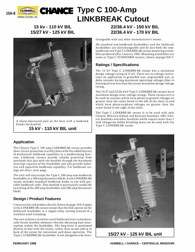
A sharp downward pull on the lever with a hookstickbreaks the fuselink.
15 kV - 110 kV BIL unit
ApplicationThe Chance Type C 100 amp LINKBREAK cutout providesshort circuit protection to utility lines with the added featureof mechanical linkbreak capability in a loadbreaking func-tion. Linkbreak cutouts provide reliable protection fromoverloads that just melt the fuselink through the maximuminterrupt capacity of the fuseholder and also provide induc-tive and capacitive loadbreak capability. For loadbreak rat-ings see chart, next page.
The unit will also accept the Type C 200 amp non-loadbreakfuseholder or a 300 amp disconnect blade. Each LINKBREAKcutout includes standard loadbreak hooks to use with por-table loadbreak tools. This method is particularly useful forswitching of the 200 amp fuseholder and 300 amp disconnectblade.
Design / Product FeaturesConstruction and product details shown on page 10A-3 applyto the LINKBREAK cutout except that the link-ejector on thelinkbreak fuseholder is a copper-alloy casting instead of astainless-steel stamping.
The unit utilizes a stainless-steel linkbreak lever to mechani-cally break fuselink elements thereby obtaining load inter-ruption within the fuseholder. The long lever is positioneddirectly in-line with the cutout, rather than on one side or inback of the cutout for convenient pull-down operation. TheType C LINKBREAK fuseholder is not designed to be inter- 15/27 kV - 125 kV BIL unit
10A-9
HUBBELL / CHANCE – CENTRALIA, MISSOURI FEBRUARY 1998
®®
POWER SYSTEMS, INC.
Type C 100-AmpLINKBREAK Cutout
LINKBREAK Cutout with NEMA Type B Bracket
F165⁄8"422mm16"406mm16"406mm
141⁄2"368mm
A16"406mm
163⁄8"416mm
163⁄8"416mm
171⁄4"438mm
B53⁄8"137mm71⁄8"181mm71⁄8"181mm81⁄2"216mm
C103⁄4"273mm121⁄2"318mm121⁄2"318mm15"381mm
D31⁄2"89
mm31⁄8"79
mm31⁄8"79
mm13⁄4"416mm
E22"559mm
263⁄4"679mm
263⁄4"679mm
321⁄2"826mm
BILkV
110
125
150
170
CapacitiveAmperes
100100100100505050
*Specifications and ordering information on next page.†Limited to grounded-wye systems with grounded-wye
loads.
InductiveAmperes
100100100100100100100
kV,Nominal
System Voltage14.414.424.924.934.534.534.5
*CutoutCatalogNumber
C720-112PBC720-114PBC720-211PB†
C720-213PB†
C720-311PB†
C720-313PB†
C720-613PB†
Loadbreak Ratings
Dimensions
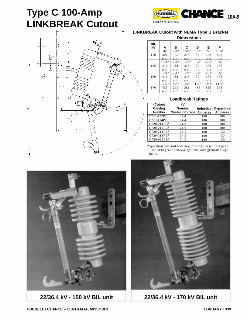
22/36.4 kV - 150 kV BIL unit 22/36.4 kV - 170 kV BIL unit
10A-10
FEBRUARY 1998 HUBBELL / CHANCE – CENTRALIA, MISSOURI
®®
POWER SYSTEMS, INC.
29.3 / 13.29
*Suffix: P = Parallel-groove clamps [No. 6 solid through 4/0 ACSR (13.3mm2 - 160.6mm2) or 250 kcmil stranded (167.5mm2)]B = B = NEMA Heavy Duty “B” bracket with 11⁄2" captive bolt
Terminal variations:P = Parallel-groove clamps [No. 6 solid through 4/0 ACSR (13.3mm2 - 160.6mm2) or 250 kcmil stranded (167.5mm2)]E = Small eyebolt [No. 8 solid through 2/0 stranded (7.7 - 90mm2)]
Change “P” to “E;” e.g., C720-112EBL = Large eyebolt [No. 6 solid through 4/0 stranded (13.3 - 160.6mm2) or 250 kcmil stranded (167.5mm2)]
Change “P” to “L;” e.g., C720-112LBBracket variations:
B = B = NEMA Heavy Duty “B” bracket with 11⁄2" captive boltX = Extended bracket (horizontal section 25⁄8" longer than NEMA Type B bracket)
Change “B” to “X;” e.g., C720-112PXD = Pole mounting bracket Change “B” to “D;” e.g., C720-112PD
(Blank) = Without crossarm bracket Drop “B” from Catalog No.; e.g., C720-112P
Extra corrosion resistance:S = Available on only 150 kV and 170 kV BIL, e.g., C720-311PBS
†For application on single-phase to neutral circuits with phase-to-ground voltages not exceeding the value to the left of theslant; and for application on three-phase solidly-grounded-wye systems with solidly-grounded loads with line-to-line voltagesnot exceeding the value to the right of the slant.
MaximumDesignVoltage15 kV15 kV
*CatalogNumber
C720-112PBC720-114PB
NominalSystem Voltage
Thru 14.4 kVThru 14.4 kV
220 mm220 mm
Weight(lb./kg.)
ArcShortening
RodNoYes
ContinuousCurrent(Amps)
100100
8.7"8.7"
Leakage to GroundMetal to Metal
InterruptCapacity
(Asym Amps)10,00016,000
17.7 / 8.0317.9 / 8.12
Specifications and Ordering InformationAll Type C Cutouts meet or exceed ANSI/NEMA specifications.
15 kV (110 kV BIL) — RUS Listed
See page 10A-17 forCatalog Number System.
22/36.4 kV
22/36.4 kV
22/36.4 kV (150 kV BIL) — RUS Listed
C720-311PB
C720-313PB
No Restrictionsthru 20.8 kV;
†22.8 thru 34.5 kV
660 mm26.0"22/36.4 kV Yes11,200
22/36.4 kV (170 kV BIL) — RUS Listed
C720-613PBNo Restrictionsthru 20.8 kV;
†22.8 thru 34.5 kV
15/27 kV
15/27 kV
No
Yes
8,000
12,000
100
100
15/27 kV (125 kV BIL) — RUS Listed
C720-211PB
C720-213PB
No Restrictionsthru 14.9 kV;
†20.8 thru 24.9 kV
12.6"
12.6"
320 mm
320 mm
lb.2.52.72.72.92.72.9
3.5
kg.1.131.221.221.321.221.32
1.59
WeightFuseholderCatalog No.T720-112TT720-114TT720-211TT720-213TT720-311TT720-313T
T720-613T
CutoutCatalog Number
C720-112PBC720-114PBC720-211PBC720-213PBC720-311PBC720-313PB
C720-613PB
kV& BIL15 kV
110 kV BIL15/27 kV
125 kV BIL22/36.4 kV150 kV BIL22/36.4 kV170 kV BIL
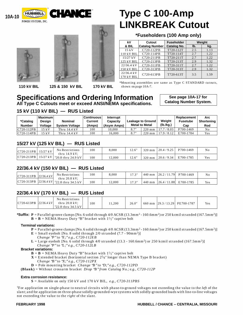
*Mounting assemblies are same as Type C STANDARD cutouts,shown on page 10A-7.
Type C 100-AmpLINKBREAK Cutout
110 kV BIL 170 kV BIL125 & 150 kV BIL
*Fuseholders (100 Amp only)
ReplacementFusetube
CapP700-1469E700-1784
P700-1469
E700-1785
20.4 / 9.25
20.6 / 9.34
No
Yes
8,000
12,000
100
100
17.3"
17.3"
440 mm
440 mm
P700-1469
E700-1785
26.2 / 11.79
26.4 / 11.88
100 PE700-1787
10A-11
HUBBELL / CHANCE – CENTRALIA, MISSOURI FEBRUARY 1998
®®
POWER SYSTEMS, INC.
B
67⁄8"175 mm
85⁄8"219 mm
85⁄8"219 mm
C
103⁄4"273 mm
121⁄2"318 mm
121⁄2"318 mm
A
251⁄4"642 mm
281⁄4"719 mm
281⁄4"719 mm
D
31⁄2"89 mm
31⁄8"79 mm
31⁄8"79 mm
E
255⁄8"651 mm
307⁄8"784 mm
307⁄8"784 mm
kV BIL
110
125
150
Dimensions
Application
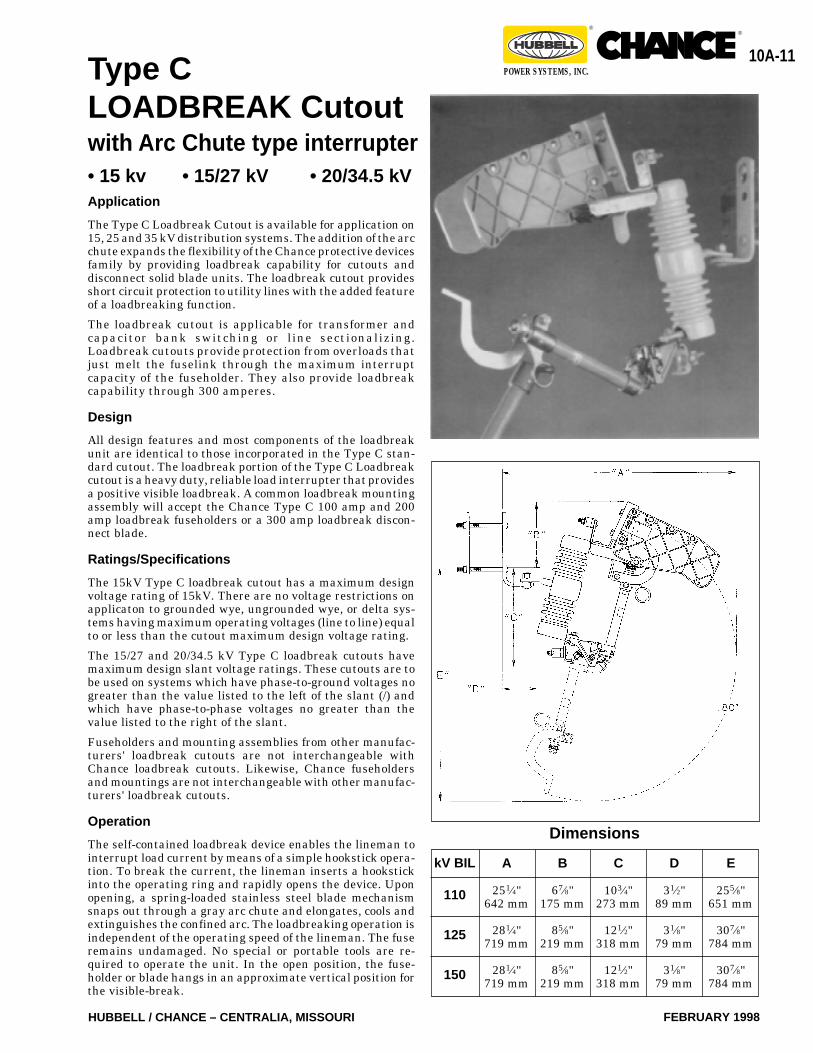
The Type C Loadbreak Cutout is available for application on15, 25 and 35 kV distribution systems. The addition of the arcchute expands the flexibility of the Chance protective devicesfamily by providing loadbreak capability for cutouts anddisconnect solid blade units. The loadbreak cutout providesshort circuit protection to utility lines with the added featureof a loadbreaking function.
The loadbreak cutout is applicable for transformer andcapacitor bank switching or line sectionalizing.Loadbreak cutouts provide protection from overloads thatjust melt the fuselink through the maximum interruptcapacity of the fuseholder. They also provide loadbreakcapability through 300 amperes.
Design
All design features and most components of the loadbreakunit are identical to those incorporated in the Type C stan-dard cutout. The loadbreak portion of the Type C Loadbreakcutout is a heavy duty, reliable load interrupter that providesa positive visible loadbreak. A common loadbreak mountingassembly will accept the Chance Type C 100 amp and 200amp loadbreak fuseholders or a 300 amp loadbreak discon-nect blade.
Ratings/Specifications
The 15kV Type C loadbreak cutout has a maximum designvoltage rating of 15kV. There are no voltage restrictions onapplicaton to grounded wye, ungrounded wye, or delta sys-tems having maximum operating voltages (line to line) equalto or less than the cutout maximum design voltage rating.
The 15/27 and 20/34.5 kV Type C loadbreak cutouts havemaximum design slant voltage ratings. These cutouts are tobe used on systems which have phase-to-ground voltages nogreater than the value listed to the left of the slant (/) andwhich have phase-to-phase voltages no greater than thevalue listed to the right of the slant.
Fuseholders and mounting assemblies from other manufac-turers' loadbreak cutouts are not interchangeable withChance loadbreak cutouts. Likewise, Chance fuseholdersand mountings are not interchangeable with other manufac-turers' loadbreak cutouts.
Operation
The self-contained loadbreak device enables the lineman tointerrupt load current by means of a simple hookstick opera-tion. To break the current, the lineman inserts a hookstickinto the operating ring and rapidly opens the device. Uponopening, a spring-loaded stainless steel blade mechanismsnaps out through a gray arc chute and elongates, cools andextinguishes the confined arc. The loadbreaking operation isindependent of the operating speed of the lineman. The fuseremains undamaged. No special or portable tools are re-quired to operate the unit. In the open position, the fuse-holder or blade hangs in an approximate vertical position forthe visible-break.
Type CLOADBREAK Cutoutwith Arc Chute type interrupter• 15 kv • 15/27 kV • 20/34.5 kV
10A-12
FEBRUARY 1998 HUBBELL / CHANCE – CENTRALIA, MISSOURI
®®
POWER SYSTEMS, INC. Type CLOADBREAK Cutout
with Arc Chute Interrrupers
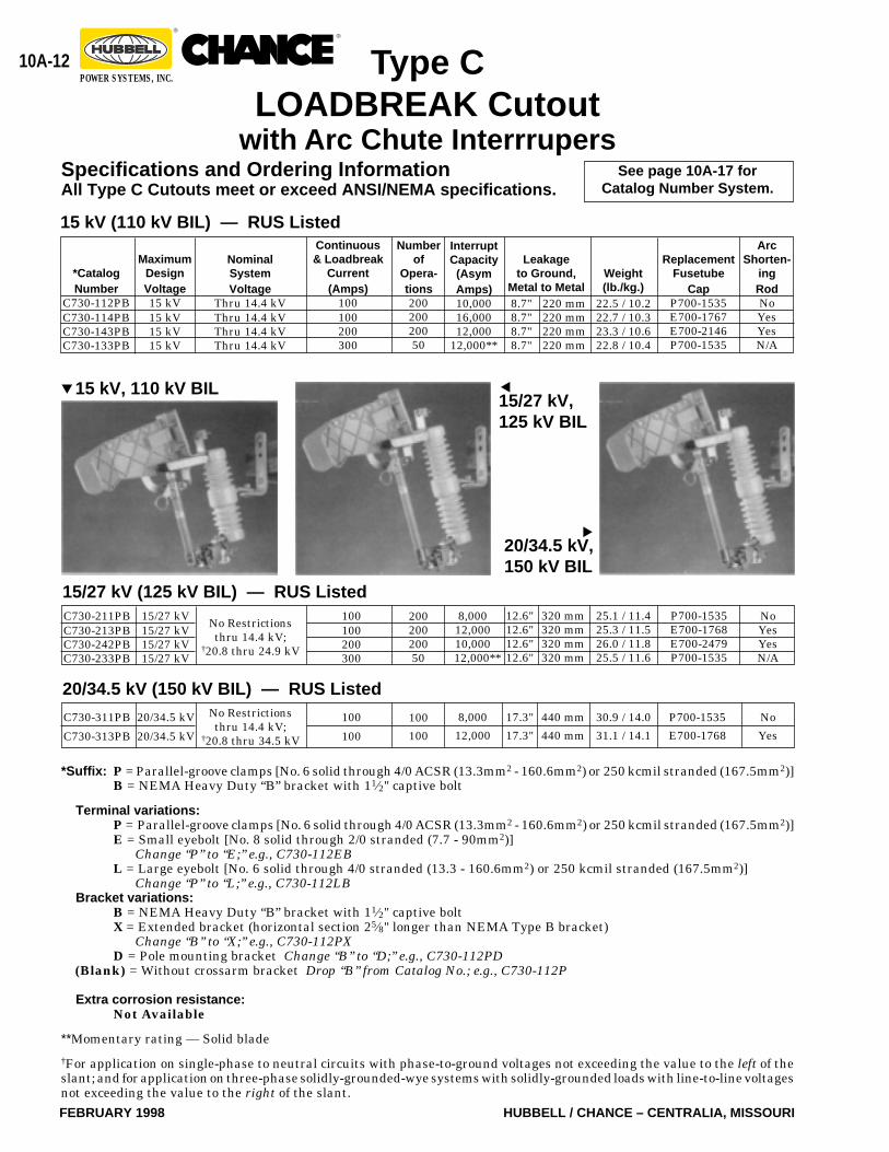
15 kV (110 kV BIL) — RUS Listed
See page 10A-17 forCatalog Number System.
NominalSystemVoltage
Thru 14.4 kVThru 14.4 kVThru 14.4 kVThru 14.4 kV
InterruptCapacity(AsymAmps)10,00016,00012,000
12,000**
22.5 / 10.222.7 / 10.323.3 / 10.622.8 / 10.4
Continuous& Loadbreak
Current(Amps)
100100200300
Weight(lb./kg.)
ArcShorten-
ingRodNoYesYesN/A
Numberof
Opera-tions20020020050
Leakageto Ground,
Metal to Metal8.7"8.7"8.7"8.7"
220 mm220 mm220 mm220 mm
MaximumDesignVoltage15 kV15 kV15 kV15 kV
*CatalogNumber
C730-112PBC730-114PBC730-143PBC730-133PB
15/27 kV (125 kV BIL) — RUS Listed
No Restrictionsthru 14.4 kV;
†20.8 thru 24.9 kV
8,00012,00010,00012,000**
100100200300
NoYesYesN/A
20020020050
15/27 kV15/27 kV15/27 kV15/27 kV
C730-211PBC730-213PBC730-242PBC730-233PB
12.6"12.6"12.6"12.6"
320 mm320 mm320 mm320 mm
20/34.5 kV (150 kV BIL) — RUS ListedNo Restrictionsthru 14.4 kV;
†20.8 thru 34.5 kV
8,000
12,000
100
100
No
Yes
100
100
C730-311PB
C730-313PB
17.3"
17.3"
440 mm
440 mm
20/34.5 kV
20/34.5 kV
*Suffix: P = Parallel-groove clamps [No. 6 solid through 4/0 ACSR (13.3mm2 - 160.6mm2) or 250 kcmil stranded (167.5mm2)]B = NEMA Heavy Duty “B” bracket with 11⁄2" captive bolt
Terminal variations:P = Parallel-groove clamps [No. 6 solid through 4/0 ACSR (13.3mm2 - 160.6mm2) or 250 kcmil stranded (167.5mm2)]E = Small eyebolt [No. 8 solid through 2/0 stranded (7.7 - 90mm2)]
Change “P” to “E;” e.g., C730-112EBL = Large eyebolt [No. 6 solid through 4/0 stranded (13.3 - 160.6mm2) or 250 kcmil stranded (167.5mm2)]
Change “P” to “L;” e.g., C730-112LBBracket variations:
B = NEMA Heavy Duty “B” bracket with 11⁄2" captive boltX = Extended bracket (horizontal section 25⁄8" longer than NEMA Type B bracket)
Change “B” to “X;” e.g., C730-112PXD = Pole mounting bracket Change “B” to “D;” e.g., C730-112PD
(Blank) = Without crossarm bracket Drop “B” from Catalog No.; e.g., C730-112P
Extra corrosion resistance:Not Available
**Momentary rating — Solid blade
†For application on single-phase to neutral circuits with phase-to-ground voltages not exceeding the value to the left of theslant; and for application on three-phase solidly-grounded-wye systems with solidly-grounded loads with line-to-line voltagesnot exceeding the value to the right of the slant.
20/34.5 kV,150 kV BIL
▼
15 kV, 110 kV BIL▼
15/27 kV,125 kV BIL
▼
Specifications and Ordering InformationAll Type C Cutouts meet or exceed ANSI/NEMA specifications.
ReplacementFusetube
CapP700-1535E700-1767E700-2146P700-1535
25.1 / 11.425.3 / 11.526.0 / 11.825.5 / 11.6
P700-1535E700-1768E700-2479P700-1535
30.9 / 14.0
31.1 / 14.1
P700-1535
E700-1768
10A-13
HUBBELL / CHANCE – CENTRALIA, MISSOURI FEBRUARY 1998
®®
POWER SYSTEMS, INC.
*Suffix: P = Parallel-groove clamps [No. 6 solid through 4/0 ACSR (13.3mm2 - 160.6mm2) or 250 kcmil stranded (167.5mm2)]B = NEMA Heavy Duty “B” bracket with 11⁄2" captive bolt
Terminal variations:P = Parallel-groove clamps [No. 6 solid through 4/0 ACSR (13.3mm2 - 160.6mm2) or 250 kcmil stranded (167.5mm2)]E = Small eyebolt [No. 8 solid through 2/0 stranded (7.7 - 90mm2)]
Change “P” to “E;” e.g., C730-2MMEBL = Large eyebolt [No. 6 solid through 4/0 stranded (13.3 - 160.6mm2) or 250 kcmil stranded (167.5mm2)]
Change “P” to “L;” e.g., C730-2MMLBBracket variations:
B = NEMA Heavy Duty “B” bracket with 11⁄2" captive boltX = Extended bracket (horizontal section 25⁄8" longer than NEMA Type B bracket)
Change “B” to “X;” e.g., C730-2MMPXD = Pole mounting bracket Change “B” to “D;” e.g., C730-2MMPD
(Blank) = Without crossarm bracket Drop “B” from Catalog No.;” e.g., C730-2MMP
110 kV, 125 kV & 150 kV BILT730-0080 Replacement Arc Chute Interrupter Assembly 0.54 kg.1.2 lb.
3.3 lb.3.5 lb.4.1 lb.3.6 lb.
CutoutCatalogNumber
C730-112PBC730-114PBC730-143PBC730-133PB
1.5 kg.1.6 kg.1.9 kg.1.6 kg.
15 kV (110 kV BIL)Mounting
Assembly only*Catalog No.
T730-1MMPB
Fuseholder orBlade onlyCatalog No.T730-112TT730-114TT730-143TT730-133T
8.4 kg.18.6 lb.
Weight Weight
20/34.5 kV (150 kV BIL)C730-311PBC730-313PB
T730-311TT730-313T
3.6 lb.3.8 lb.
1.6 kg.1.7 kg. 12.1 kg.26.6 lb.T730-3MMPB
3.6 lb.3.8 lb.4.4 lb.4.0 lb.
9.4 kg.20.8 lb.T730-2MMPB
1.6 kg.1.7 kg.2.0 kg.1.8 kg.
T730-211TT730-213TT730-242TT730-233T
15/27 kV (125 kV BIL)C730-211PBC730-213PBC730-242PBC730-233PB
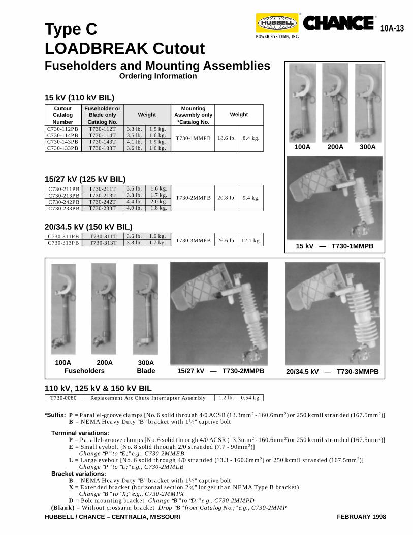
20/34.5 kV — T730-3MMPB15/27 kV — T730-2MMPB
15 kV — T730-1MMPB
200A100A 300A
300ABladeFuseholders
100A 200A
Type CLOADBREAK CutoutFuseholders and Mounting Assemblies
Ordering Information
10A-14
FEBRUARY 1998 HUBBELL / CHANCE – CENTRALIA, MISSOURI
®®
POWER SYSTEMS, INC.
Direct
Direct
Direct
Small BlockNormal Duty
5 kA
Large BlockHeavy Duty
10 kA
RiserPole
Oh
io B
rass
9
DL
EL
FL
10
DM
EM
FM
18
DN
EN
FN
27
DP
EP
FP
125 &150 150110
Polymer
Metal Oxide Varister (MOV)OperatingDesign
Housing
kV BILfor Cutout
kV RatingMC
OV
Dut
y C
ycle
kV R
atin
g
Arr
este
r Man
ufac
ture
r
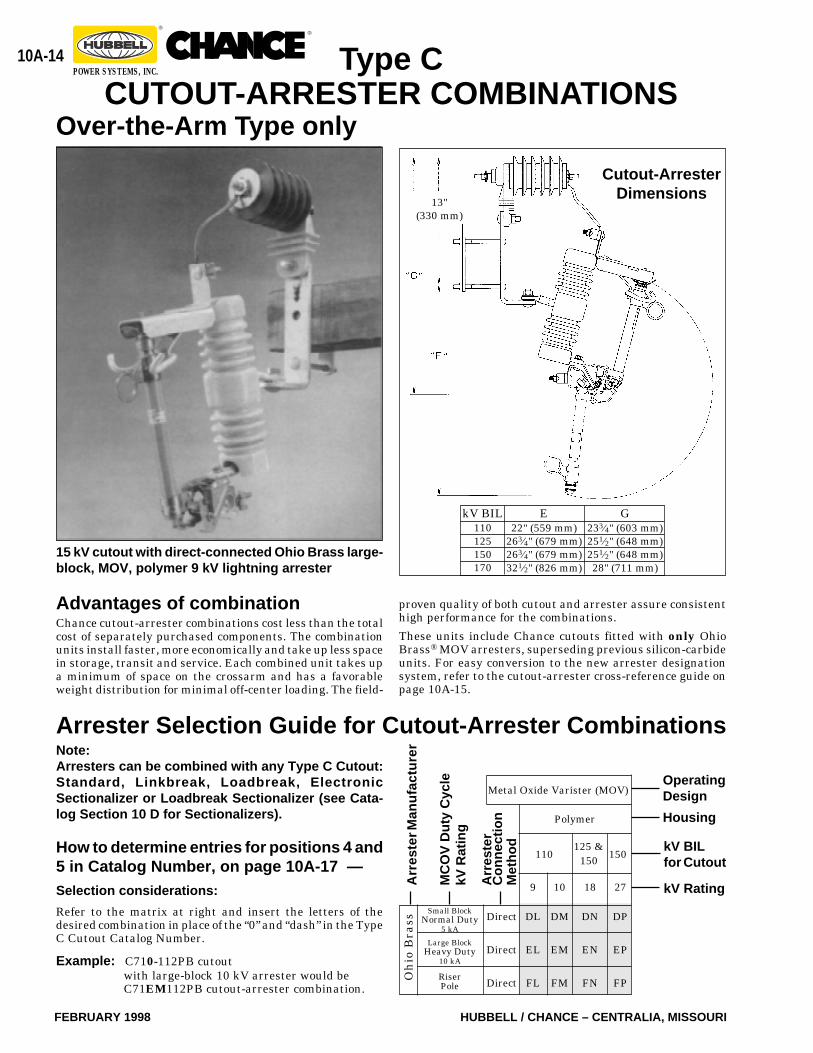
Selection considerations:
Refer to the matrix at right and insert the letters of thedesired combination in place of the “0” and “dash” in the TypeC Cutout Catalog Number.
Example: C710-112PB cutoutwith large-block 10 kV arrester would beC71EM112PB cutout-arrester combination.
G233⁄4" (603 mm)251⁄2" (648 mm)251⁄2" (648 mm)28" (711 mm)
E22" (559 mm)
263⁄4" (679 mm)263⁄4" (679 mm)321⁄2" (826 mm)
kV BIL110125150170
Arrester Selection Guide for Cutout-Arrester Combinations
Type CCUTOUT-ARRESTER COMBINATIONS
15 kV cutout with direct-connected Ohio Brass large-block, MOV, polymer 9 kV lightning arrester
Advantages of combinationChance cutout-arrester combinations cost less than the totalcost of separately purchased components. The combinationunits install faster, more economically and take up less spacein storage, transit and service. Each combined unit takes upa minimum of space on the crossarm and has a favorableweight distribution for minimal off-center loading. The field-
Over-the-Arm Type only
Cutout-ArresterDimensions
How to determine entries for positions 4 and5 in Catalog Number, on page 10A-17 —
Arr
este
rC
onne
ctio
nM
etho
d
13"(330 mm)
proven quality of both cutout and arrester assure consistenthigh performance for the combinations.
These units include Chance cutouts fitted with only OhioBrass® MOV arresters, superseding previous silicon-carbideunits. For easy conversion to the new arrester designationsystem, refer to the cutout-arrester cross-reference guide onpage 10A-15.
Note:Arresters can be combined with any Type C Cutout:Standard, Linkbreak, Loadbreak, ElectronicSectionalizer or Loadbreak Sectionalizer (see Cata-log Section 10 D for Sectionalizers).
10A-15
HUBBELL / CHANCE – CENTRALIA, MISSOURI FEBRUARY 1998
®®
POWER SYSTEMS, INC.
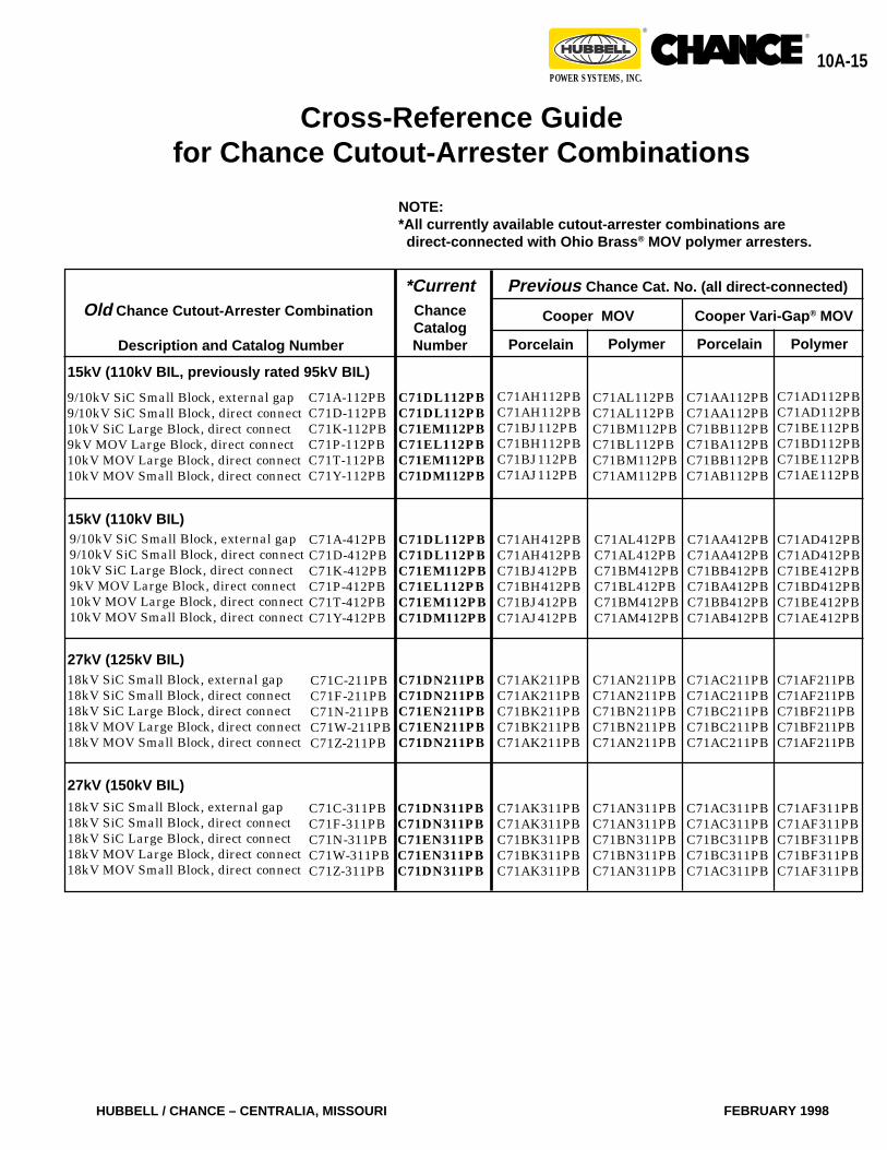
Cross-Reference Guidefor Chance Cutout-Arrester Combinations
C71AL112PBC71AL112PBC71BM112PBC71BL112PBC71BM112PBC71AM112PB
C71AA112PBC71AA112PBC71BB112PBC71BA112PBC71BB112PBC71AB112PB
C71AD112PBC71AD112PBC71BE112PBC71BD112PBC71BE112PBC71AE112PB
Porcelain Porcelain PolymerPolymer
C71AH112PBC71AH112PBC71BJ112PBC71BH112PBC71BJ112PBC71AJ112PB
Cooper Vari-Gap ® MOVCooper MOV
Previous Chance Cat. No. (all direct-connected)*CurrentChanceCatalogNumber
C71DL112PBC71DL112PBC71EM112PBC71EL112PBC71EM112PBC71DM112PB
NOTE:*All currently available cutout-arrester combinations are
direct-connected with Ohio Brass ® MOV polymer arresters.
C71A-112PBC71D-112PBC71K-112PBC71P-112PBC71T-112PBC71Y-112PB
15kV (110kV BIL, previously rated 95kV BIL)
9/10kV SiC Small Block, external gap9/10kV SiC Small Block, direct connect10kV SiC Large Block, direct connect9kV MOV Large Block, direct connect10kV MOV Large Block, direct connect10kV MOV Small Block, direct connect
C71AF211PBC71AF211PBC71BF211PBC71BF211PBC71AF211PB
C71AN311PBC71AN311PBC71BN311PBC71BN311PBC71AN311PB
C71AC311PBC71AC311PBC71BC311PBC71BC311PBC71AC311PB
C71AF311PBC71AF311PBC71BF311PBC71BF311PBC71AF311PB
C71DN311PBC71DN311PBC71EN311PBC71EN311PBC71DN311PB
C71AK311PBC71AK311PBC71BK311PBC71BK311PBC71AK311PB
C71AC211PBC71AC211PBC71BC211PBC71BC211PBC71AC211PB
C71AN211PBC71AN211PBC71BN211PBC71BN211PBC71AN211PB
C71AK211PBC71AK211PBC71BK211PBC71BK211PBC71AK211PB
C71DN211PBC71DN211PBC71EN211PBC71EN211PBC71DN211PB
C71DL112PBC71DL112PBC71EM112PBC71EL112PBC71EM112PBC71DM112PB
C71AH412PBC71AH412PBC71BJ412PBC71BH412PBC71BJ412PBC71AJ412PB
C71AL412PBC71AL412PBC71BM412PBC71BL412PBC71BM412PBC71AM412PB
C71AA412PBC71AA412PBC71BB412PBC71BA412PBC71BB412PBC71AB412PB
C71AD412PBC71AD412PBC71BE412PBC71BD412PBC71BE412PBC71AE412PB
C71C-211PBC71F-211PBC71N-211PBC71W-211PBC71Z-211PB
C71C-311PBC71F-311PBC71N-311PBC71W-311PBC71Z-311PB
C71A-412PBC71D-412PBC71K-412PBC71P-412PBC71T-412PBC71Y-412PB
15kV (110kV BIL)9/10kV SiC Small Block, external gap9/10kV SiC Small Block, direct connect10kV SiC Large Block, direct connect9kV MOV Large Block, direct connect10kV MOV Large Block, direct connect10kV MOV Small Block, direct connect
27kV (125kV BIL)18kV SiC Small Block, external gap18kV SiC Small Block, direct connect18kV SiC Large Block, direct connect18kV MOV Large Block, direct connect18kV MOV Small Block, direct connect
27kV (150kV BIL)18kV SiC Small Block, external gap18kV SiC Small Block, direct connect18kV SiC Large Block, direct connect18kV MOV Large Block, direct connect18kV MOV Small Block, direct connect
Description and Catalog Number
Old Chance Cutout-Arrester Combination
10A-16
FEBRUARY 1998 HUBBELL / CHANCE – CENTRALIA, MISSOURI
®®
POWER SYSTEMS, INC.
Interrupting orMomentary Current
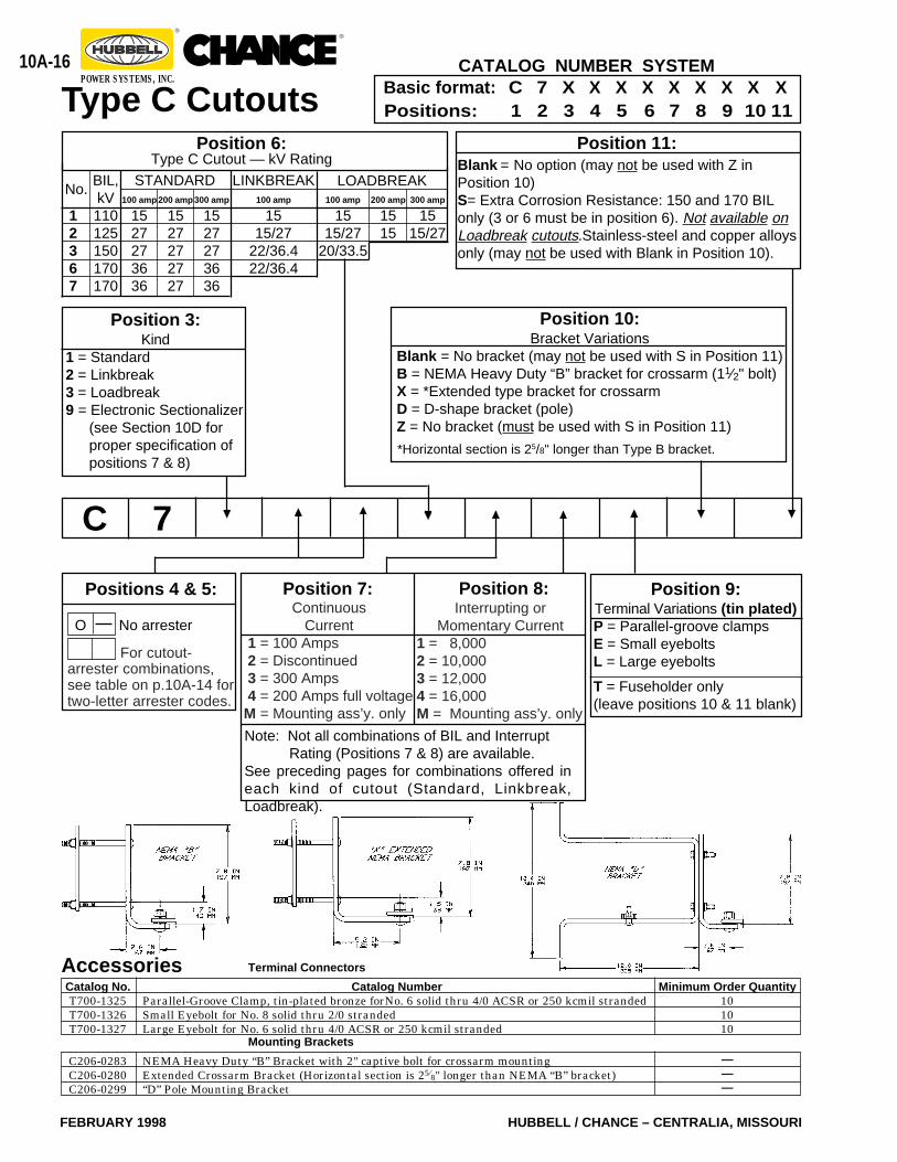
1 = 8,0002 = 10,0003 = 12,0004 = 16,000M = Mounting ass’y. only
Type C Cutouts
For cutout-arrester combinations,see table on p.10A-14 fortwo-letter arrester codes.
7C
Position 10:Bracket Variations
Blank = No bracket (may not be used with S in Position 11)B = NEMA Heavy Duty “B” bracket for crossarm (11⁄2" bolt)X = *Extended type bracket for crossarmD = D-shape bracket (pole)Z = No bracket (must be used with S in Position 11)
*Horizontal section is 25/8" longer than Type B bracket.
Position 11:Blank = No option (may not be used with Z inPosition 10)S= Extra Corrosion Resistance: 150 and 170 BILonly (3 or 6 must be in position 6). Not available onLoadbreak cutouts.Stainless-steel and copper alloysonly (may not be used with Blank in Position 10).
Basic format: C 7 X X X X X X X X XPositions: 1 2 3 4 5 6 7 8 9 10 11
CATALOG NUMBER SYSTEM
Position 9:Terminal Variations (tin plated)P = Parallel-groove clampsE = Small eyeboltsL = Large eyebolts
T = Fuseholder only(leave positions 10 & 11 blank)
Positions 4 & 5:
O No arrester
Position 6:Type C Cutout — kV Rating
STANDARD100 amp
1527273636
200 amp
1527272727
300 amp
1527273636
LINKBREAK100 amp
1515/27
22/36.422/36.4
LOADBREAKBIL,kV110125150170170
No.
12367
100 amp
1515/27
20/33.5
200 amp
1515
300 amp
1515/27
Position 3:Kind
1 = Standard2 = Linkbreak3 = Loadbreak9 = Electronic Sectionalizer
(see Section 10D forproper specification ofpositions 7 & 8)
Position 7:Continuous
Current1 = 100 Amps2 = Discontinued3 = 300 Amps4 = 200 Amps full voltage
M = Mounting ass’y. only
Position 8:
Note: Not all combinations of BIL and Interrupt Rating (Positions 7 & 8) are available.See preceding pages for combinations offered ineach kind of cutout (Standard, Linkbreak,Loadbreak).
AccessoriesCatalog No.T700-1325T700-1326T700-1327
Terminal Connectors
Minimum Order Quantity101010
Catalog NumberParallel-Groove Clamp, tin-plated bronze forNo. 6 solid thru 4/0 ACSR or 250 kcmil strandedSmall Eyebolt for No. 8 solid thru 2/0 strandedLarge Eyebolt for No. 6 solid thru 4/0 ACSR or 250 kcmil stranded
C206-0283C206-0280C206-0299
Mounting Brackets———
NEMA Heavy Duty “B” Bracket with 2" captive bolt for crossarm mountingExtended Crossarm Bracket (Horizontal section is 25⁄8" longer than NEMA “B” bracket)“D” Pole Mounting Bracket
10A-17
HUBBELL / CHANCE – CENTRALIA, MISSOURI FEBRUARY 1998
®®
POWER SYSTEMS, INC.
†kV & BIL
15 kV110 BIL
27 kV125 BIL
27 kV150 BIL
36 kV, 170 BIL27 kV, 170 BIL36 kV, 170 BIL36 kV, 170 BIL27 kV, 170 BIL36 kV, 170 BIL
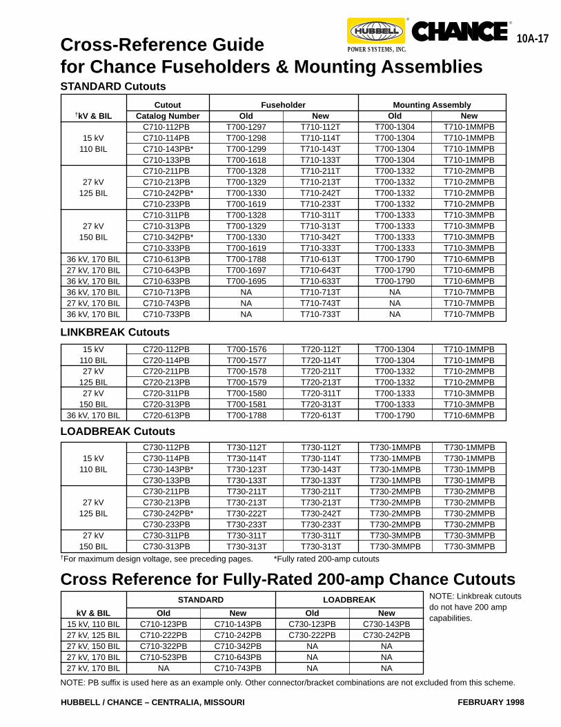
OldT700-1297T700-1298T700-1299T700-1618T700-1328T700-1329T700-1330T700-1619T700-1328T700-1329T700-1330T700-1619T700-1788T700-1697T700-1695
NANANA
NewT710-112TT710-114TT710-143TT710-133TT710-211TT710-213TT710-242TT710-233TT710-311TT710-313TT710-342TT710-333TT710-613TT710-643TT710-633TT710-713TT710-743TT710-733T
OldT700-1304T700-1304T700-1304T700-1304T700-1332T700-1332T700-1332T700-1332T700-1333T700-1333T700-1333T700-1333T700-1790T700-1790T700-1790
NANANA
NewT710-1MMPBT710-1MMPBT710-1MMPBT710-1MMPBT710-2MMPBT710-2MMPBT710-2MMPBT710-2MMPBT710-3MMPBT710-3MMPBT710-3MMPBT710-3MMPBT710-6MMPBT710-6MMPBT710-6MMPBT710-7MMPBT710-7MMPBT710-7MMPB
CutoutCatalog Number
C710-112PBC710-114PBC710-143PB*C710-133PBC710-211PBC710-213PBC710-242PB*C710-233PBC710-311PBC710-313PBC710-342PB*C710-333PBC710-613PBC710-643PBC710-633PBC710-713PBC710-743PBC710-733PB
Fuseholder Mounting Assembly
STANDARD Cutouts
15 kV110 BIL27 kV
125 BIL27 kV
150 BIL36 kV, 170 BIL
C720-112PBC720-114PBC720-211PBC720-213PBC720-311PBC720-313PBC720-613PB
T700-1576T700-1577T700-1578T700-1579T700-1580T700-1581T700-1788
T720-112TT720-114TT720-211TT720-213TT720-311TT720-313TT720-613T
LINKBREAK CutoutsT700-1304T700-1304T700-1332T700-1332T700-1333T700-1333T700-1790
T710-1MMPBT710-1MMPBT710-2MMPBT710-2MMPBT710-3MMPBT710-3MMPBT710-6MMPB
†For maximum design voltage, see preceding pages. *Fully rated 200-amp cutouts
T730-112TT730-114TT730-123TT730-133TT730-211TT730-213TT730-222TT730-233TT730-311TT730-313T
T730-112TT730-114TT730-143TT730-133TT730-211TT730-213TT730-242TT730-233TT730-311TT730-313T
T730-1MMPBT730-1MMPBT730-1MMPBT730-1MMPBT730-2MMPBT730-2MMPBT730-2MMPBT730-2MMPBT730-3MMPBT730-3MMPB
T730-1MMPBT730-1MMPBT730-1MMPBT730-1MMPBT730-2MMPBT730-2MMPBT730-2MMPBT730-2MMPBT730-3MMPBT730-3MMPB
15 kV110 BIL
27 kV125 BIL
27 kV150 BIL
C730-112PBC730-114PBC730-143PB*C730-133PBC730-211PBC730-213PBC730-242PB*C730-233PBC730-311PBC730-313PB
LOADBREAK Cutouts
Cross-Reference Guidefor Chance Fuseholders & Mounting Assemblies
Cross Reference for Fully-Rated 200-amp Chance Cutouts
kV & BIL15 kV, 110 BIL27 kV, 125 BIL27 kV, 150 BIL27 kV, 170 BIL27 kV, 170 BIL
OldC710-123PBC710-222PBC710-322PBC710-523PB
NA
NewC710-143PBC710-242PBC710-342PBC710-643PBC710-743PB
OldC730-123PBC730-222PB
NANANA
NewC730-143PBC730-242PB
NANANA
STANDARD LOADBREAK NOTE: Linkbreak cutoutsdo not have 200 ampcapabilities.
NOTE: PB suffix is used here as an example only. Other connector/bracket combinations are not excluded from this scheme.
10A-18
FEBRUARY 1998 HUBBELL / CHANCE – CENTRALIA, MISSOURI
®®
POWER SYSTEMS, INC.
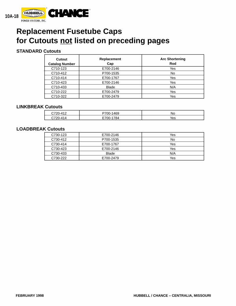
ReplacementCap
Arc ShorteningRodYesNoYesYesN/AYesYes
CutoutCatalog Number
C710-123C710-412C710-414C710-423C710-433C710-222C710-322
STANDARD Cutouts
Replacement Fusetube Capsfor Cutouts not listed on preceding pages
E700-2146P700-1535E700-1767E700-2146
BladeE700-2479E700-2479
C720-412C720-414
LINKBREAK CutoutsP700-1469E700-1784
NoYes
YesNoYesYesN/AYes
C730-123C730-412C730-414C730-423C730-433C730-222
LOADBREAK CutoutsE700-2146P700-1535E700-1767E700-2146
BladeE700-2479

10A-19
HUBBELL / CHANCE – CENTRALIA, MISSOURI FEBRUARY 1998
®®
POWER SYSTEMS, INC.

10A-20
FEBRUARY 1998 HUBBELL / CHANCE – CENTRALIA, MISSOURI
®®
POWER SYSTEMS, INC.