Embed Size (px)
Citation preview
Power Systems
7316-TF3 17-Inch Flat PanelRack-Mounted Monitor and Keyboard
SA38-0643-01
���

Power Systems
7316-TF3 17-Inch Flat PanelRack-Mounted Monitor and Keyboard
SA38-0643-01
���
NoteBefore using this information and the product it supports, read the information in “Safety notices” on page v, “Notices” onpage 25, the IBM Systems Safety Notices manual, G229-9054, and the IBM Environmental Notices and User Guide, Z125–5823.
This edition applies to IBM Power Systems™ servers that contain the POWER7 processor and to all associatedmodels.
© Copyright IBM Corporation 2004, 2013.US Government Users Restricted Rights – Use, duplication or disclosure restricted by GSA ADP Schedule Contractwith IBM Corp.
Contents
Safety notices . . . . . . . . . . . . . . . . . . . . . . . . . . . . . . . . . v
About This Document. . . . . . . . . . . . . . . . . . . . . . . . . . . . . . 1References to AIX Operating System . . . . . . . . . . . . . . . . . . . . . . . . . . . 1Highlighting . . . . . . . . . . . . . . . . . . . . . . . . . . . . . . . . . . . 1Related Publications . . . . . . . . . . . . . . . . . . . . . . . . . . . . . . . . . 1
Introduction . . . . . . . . . . . . . . . . . . . . . . . . . . . . . . . . . . 3Check Your Inventory . . . . . . . . . . . . . . . . . . . . . . . . . . . . . . . . 3
Installing the 7316-TF3 17-Inch Flat Panel Rack-Mounted Monitor and Keyboard . . . . 5Safety Considerations . . . . . . . . . . . . . . . . . . . . . . . . . . . . . . . . 5Installing the monitor and keyboard into a rack . . . . . . . . . . . . . . . . . . . . . . . 6Installing the Optional Console Switch . . . . . . . . . . . . . . . . . . . . . . . . . . 12
Using the Monitor . . . . . . . . . . . . . . . . . . . . . . . . . . . . . . . 15User Controls. . . . . . . . . . . . . . . . . . . . . . . . . . . . . . . . . . . 15Technical Specifications . . . . . . . . . . . . . . . . . . . . . . . . . . . . . . . 16
Hardware Maintenance Information . . . . . . . . . . . . . . . . . . . . . . . 19Customer-Replaceable Unit Part Numbers . . . . . . . . . . . . . . . . . . . . . . . . . 19Replacing the Display and Keyboard . . . . . . . . . . . . . . . . . . . . . . . . . . . 19Replacing the Keyboard . . . . . . . . . . . . . . . . . . . . . . . . . . . . . . . 23
Notices . . . . . . . . . . . . . . . . . . . . . . . . . . . . . . . . . . . 25Trademarks . . . . . . . . . . . . . . . . . . . . . . . . . . . . . . . . . . . 26Electronic emission notices . . . . . . . . . . . . . . . . . . . . . . . . . . . . . . 26
Class A Notices . . . . . . . . . . . . . . . . . . . . . . . . . . . . . . . . . 26Class B Notices . . . . . . . . . . . . . . . . . . . . . . . . . . . . . . . . . 30
Terms and conditions . . . . . . . . . . . . . . . . . . . . . . . . . . . . . . . . 33
© Copyright IBM Corp. 2004, 2013 iii

iv Power Systems: 7316-TF3 17-Inch Flat Panel Rack-Mounted Monitor and Keyboard
Safety notices
Safety notices may be printed throughout this guide:v DANGER notices call attention to a situation that is potentially lethal or extremely hazardous to
people.v CAUTION notices call attention to a situation that is potentially hazardous to people because of some
existing condition.v Attention notices call attention to the possibility of damage to a program, device, system, or data.
World Trade safety information
Several countries require the safety information contained in product publications to be presented in theirnational languages. If this requirement applies to your country, safety information documentation isincluded in the publications package (such as in printed documentation, on DVD, or as part of theproduct) shipped with the product. The documentation contains the safety information in your nationallanguage with references to the U.S. English source. Before using a U.S. English publication to install,operate, or service this product, you must first become familiar with the related safety informationdocumentation. You should also refer to the safety information documentation any time you do notclearly understand any safety information in the U.S. English publications.
Replacement or additional copies of safety information documentation can be obtained by calling the IBMHotline at 1-800-300-8751.
German safety information
Das Produkt ist nicht für den Einsatz an Bildschirmarbeitsplätzen im Sinne § 2 derBildschirmarbeitsverordnung geeignet.
Laser safety information
IBM® servers can use I/O cards or features that are fiber-optic based and that utilize lasers or LEDs.
Laser compliance
IBM servers may be installed inside or outside of an IT equipment rack.
© Copyright IBM Corp. 2004, 2013 v
DANGER
When working on or around the system, observe the following precautions:
Electrical voltage and current from power, telephone, and communication cables are hazardous. Toavoid a shock hazard:v Connect power to this unit only with the IBM provided power cord. Do not use the IBM
provided power cord for any other product.v Do not open or service any power supply assembly.v Do not connect or disconnect any cables or perform installation, maintenance, or reconfiguration
of this product during an electrical storm.v The product might be equipped with multiple power cords. To remove all hazardous voltages,
disconnect all power cords.v Connect all power cords to a properly wired and grounded electrical outlet. Ensure that the outlet
supplies proper voltage and phase rotation according to the system rating plate.v Connect any equipment that will be attached to this product to properly wired outlets.v When possible, use one hand only to connect or disconnect signal cables.v Never turn on any equipment when there is evidence of fire, water, or structural damage.v Disconnect the attached power cords, telecommunications systems, networks, and modems before
you open the device covers, unless instructed otherwise in the installation and configurationprocedures.
v Connect and disconnect cables as described in the following procedures when installing, moving,or opening covers on this product or attached devices.
To Disconnect:1. Turn off everything (unless instructed otherwise).2. Remove the power cords from the outlets.3. Remove the signal cables from the connectors.4. Remove all cables from the devices.
To Connect:1. Turn off everything (unless instructed otherwise).2. Attach all cables to the devices.3. Attach the signal cables to the connectors.4. Attach the power cords to the outlets.5. Turn on the devices.
(D005)
DANGER
vi Power Systems: 7316-TF3 17-Inch Flat Panel Rack-Mounted Monitor and Keyboard
Observe the following precautions when working on or around your IT rack system:
v Heavy equipment–personal injury or equipment damage might result if mishandled.
v Always lower the leveling pads on the rack cabinet.
v Always install stabilizer brackets on the rack cabinet.
v To avoid hazardous conditions due to uneven mechanical loading, always install the heaviestdevices in the bottom of the rack cabinet. Always install servers and optional devices startingfrom the bottom of the rack cabinet.
v Rack-mounted devices are not to be used as shelves or work spaces. Do not place objects on topof rack-mounted devices.
v Each rack cabinet might have more than one power cord. Be sure to disconnect all power cords inthe rack cabinet when directed to disconnect power during servicing.
v Connect all devices installed in a rack cabinet to power devices installed in the same rackcabinet. Do not plug a power cord from a device installed in one rack cabinet into a powerdevice installed in a different rack cabinet.
v An electrical outlet that is not correctly wired could place hazardous voltage on the metal parts ofthe system or the devices that attach to the system. It is the responsibility of the customer toensure that the outlet is correctly wired and grounded to prevent an electrical shock.
CAUTION
v Do not install a unit in a rack where the internal rack ambient temperatures will exceed themanufacturer's recommended ambient temperature for all your rack-mounted devices.
v Do not install a unit in a rack where the air flow is compromised. Ensure that air flow is notblocked or reduced on any side, front, or back of a unit used for air flow through the unit.
v Consideration should be given to the connection of the equipment to the supply circuit so thatoverloading of the circuits does not compromise the supply wiring or overcurrent protection. Toprovide the correct power connection to a rack, refer to the rating labels located on theequipment in the rack to determine the total power requirement of the supply circuit.
v (For sliding drawers.) Do not pull out or install any drawer or feature if the rack stabilizer bracketsare not attached to the rack. Do not pull out more than one drawer at a time. The rack mightbecome unstable if you pull out more than one drawer at a time.
v (For fixed drawers.) This drawer is a fixed drawer and must not be moved for servicing unlessspecified by the manufacturer. Attempting to move the drawer partially or completely out of therack might cause the rack to become unstable or cause the drawer to fall out of the rack.
(R001)
Safety notices vii
CAUTION:Removing components from the upper positions in the rack cabinet improves rack stability duringrelocation. Follow these general guidelines whenever you relocate a populated rack cabinet within aroom or building:
v Reduce the weight of the rack cabinet by removing equipment starting at the top of the rackcabinet. When possible, restore the rack cabinet to the configuration of the rack cabinet as youreceived it. If this configuration is not known, you must observe the following precautions:
– Remove all devices in the 32U position and above.
– Ensure that the heaviest devices are installed in the bottom of the rack cabinet.
– Ensure that there are no empty U-levels between devices installed in the rack cabinet below the32U level.
v If the rack cabinet you are relocating is part of a suite of rack cabinets, detach the rack cabinet fromthe suite.
v Inspect the route that you plan to take to eliminate potential hazards.
v Verify that the route that you choose can support the weight of the loaded rack cabinet. Refer to thedocumentation that comes with your rack cabinet for the weight of a loaded rack cabinet.
v Verify that all door openings are at least 760 x 230 mm (30 x 80 in.).
v Ensure that all devices, shelves, drawers, doors, and cables are secure.
v Ensure that the four leveling pads are raised to their highest position.
v Ensure that there is no stabilizer bracket installed on the rack cabinet during movement.
v Do not use a ramp inclined at more than 10 degrees.
v When the rack cabinet is in the new location, complete the following steps:
– Lower the four leveling pads.
– Install stabilizer brackets on the rack cabinet.
– If you removed any devices from the rack cabinet, repopulate the rack cabinet from the lowestposition to the highest position.
v If a long-distance relocation is required, restore the rack cabinet to the configuration of the rackcabinet as you received it. Pack the rack cabinet in the original packaging material, or equivalent.Also lower the leveling pads to raise the casters off of the pallet and bolt the rack cabinet to thepallet.
(R002)
(L001)
(L002)
viii Power Systems: 7316-TF3 17-Inch Flat Panel Rack-Mounted Monitor and Keyboard
(L003)
or
All lasers are certified in the U.S. to conform to the requirements of DHHS 21 CFR Subchapter J for class1 laser products. Outside the U.S., they are certified to be in compliance with IEC 60825 as a class 1 laserproduct. Consult the label on each part for laser certification numbers and approval information.
CAUTION:This product might contain one or more of the following devices: CD-ROM drive, DVD-ROM drive,DVD-RAM drive, or laser module, which are Class 1 laser products. Note the following information:
v Do not remove the covers. Removing the covers of the laser product could result in exposure tohazardous laser radiation. There are no serviceable parts inside the device.
v Use of the controls or adjustments or performance of procedures other than those specified hereinmight result in hazardous radiation exposure.
(C026)
Safety notices ix
CAUTION:Data processing environments can contain equipment transmitting on system links with laser modulesthat operate at greater than Class 1 power levels. For this reason, never look into the end of an opticalfiber cable or open receptacle. (C027)
CAUTION:This product contains a Class 1M laser. Do not view directly with optical instruments. (C028)
CAUTION:Some laser products contain an embedded Class 3A or Class 3B laser diode. Note the followinginformation: laser radiation when open. Do not stare into the beam, do not view directly with opticalinstruments, and avoid direct exposure to the beam. (C030)
CAUTION:The battery contains lithium. To avoid possible explosion, do not burn or charge the battery.
Do Not:v ___ Throw or immerse into waterv ___ Heat to more than 100°C (212°F)v ___ Repair or disassemble
Exchange only with the IBM-approved part. Recycle or discard the battery as instructed by localregulations. In the United States, IBM has a process for the collection of this battery. For information,call 1-800-426-4333. Have the IBM part number for the battery unit available when you call. (C003)
Power and cabling information for NEBS (Network Equipment-Building System)GR-1089-CORE
The following comments apply to the IBM servers that have been designated as conforming to NEBS(Network Equipment-Building System) GR-1089-CORE:
The equipment is suitable for installation in the following:v Network telecommunications facilitiesv Locations where the NEC (National Electrical Code) applies
The intrabuilding ports of this equipment are suitable for connection to intrabuilding or unexposedwiring or cabling only. The intrabuilding ports of this equipment must not be metallically connected to theinterfaces that connect to the OSP (outside plant) or its wiring. These interfaces are designed for use asintrabuilding interfaces only (Type 2 or Type 4 ports as described in GR-1089-CORE) and require isolationfrom the exposed OSP cabling. The addition of primary protectors is not sufficient protection to connectthese interfaces metallically to OSP wiring.
Note: All Ethernet cables must be shielded and grounded at both ends.
The ac-powered system does not require the use of an external surge protection device (SPD).
The dc-powered system employs an isolated DC return (DC-I) design. The DC battery return terminalshall not be connected to the chassis or frame ground.
x Power Systems: 7316-TF3 17-Inch Flat Panel Rack-Mounted Monitor and Keyboard
About This Document
This document provides information on how to install the IBM® 7316-TF3 17-Inch Flat PanelRack-Mounted Monitor and Keyboard.
References to AIX Operating SystemThis document may contain references to the AIX® operating system. If you are using another operatingsystem, consult the appropriate documentation for that operating system.
This document may describe hardware features and functions. While the hardware supports them, therealization of these features and functions depends upon support from the operating system. AIXprovides this support. If you are using another operating system, consult the appropriate documentationfor that operating system regarding support for those features and functions.
HighlightingThe following highlighting conventions are used in this document:
Bold Identifies commands, subroutines, keywords, files,structures, directories, and other items whose names arepredefined by the system. Also identifies graphical objectssuch as buttons, labels, and icons that the user selects.
Italics Identifies parameters whose actual names or values are tobe supplied by the user.
Monospace Identifies examples of specific data values, examples oftext similar to what you might see displayed, examples ofportions of program code similar to what you mightwrite as a programmer, messages from the system, orinformation you should actually type.
Related PublicationsThe following publications contain related information:v System unit documentation for information specific to your hardware configuration.v Operating system documentation for information specific to your software configuration.
© Copyright IBM Corp. 2004, 2013 1

2 Power Systems: 7316-TF3 17-Inch Flat Panel Rack-Mounted Monitor and Keyboard
Introduction
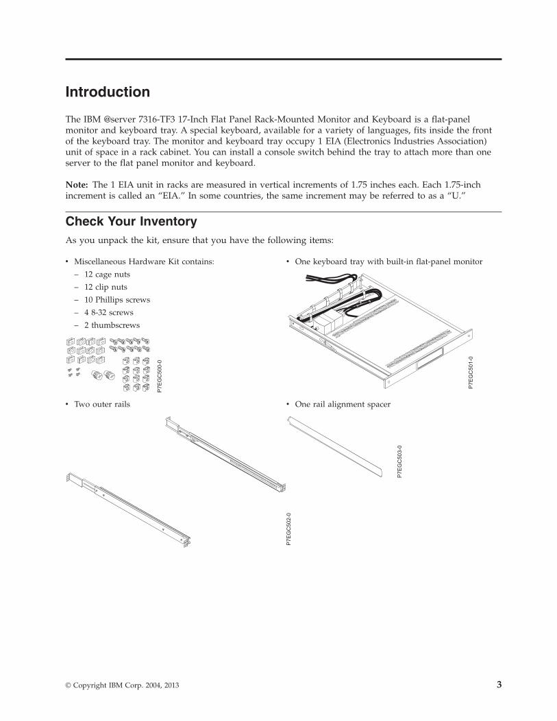
The IBM @server 7316-TF3 17-Inch Flat Panel Rack-Mounted Monitor and Keyboard is a flat-panelmonitor and keyboard tray. A special keyboard, available for a variety of languages, fits inside the frontof the keyboard tray. The monitor and keyboard tray occupy 1 EIA (Electronics Industries Association)unit of space in a rack cabinet. You can install a console switch behind the tray to attach more than oneserver to the flat panel monitor and keyboard.
Note: The 1 EIA unit in racks are measured in vertical increments of 1.75 inches each. Each 1.75-inchincrement is called an “EIA.” In some countries, the same increment may be referred to as a “U.”
Check Your InventoryAs you unpack the kit, ensure that you have the following items:
v Miscellaneous Hardware Kit contains:
– 12 cage nuts
– 12 clip nuts
– 10 Phillips screws
– 4 8-32 screws
– 2 thumbscrews
P7E
GC
500-0
v One keyboard tray with built-in flat-panel monitor
P7E
GC
501-0
v Two outer rails
P7E
GC
502-0
v One rail alignment spacerP
7E
GC
503-0
© Copyright IBM Corp. 2004, 2013 3
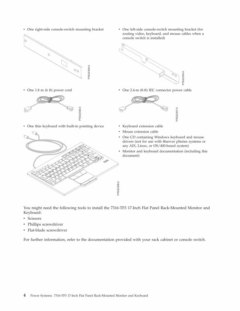
v One right-side console-switch mounting bracket
P7E
GC
504-0
v One left-side console-switch mounting bracket (forrouting video, keyboard, and mouse cables when aconsole switch is installed)
P7E
GC
505-0
v One 1.8 m (6 ft) power cord
P7E
GC
506
-0
v One 2.4-m (8-ft) IEC connector power cable
P7E
GC
507-0
v One thin keyboard with built-in pointing device
P7E
GC
508-0
v Keyboard extension cable
v Mouse extension cable
v One CD containing Windows keyboard and mousedrivers (not for use with @server pSeries systems orany AIX, Linux, or OS/400-based system)
v Monitor and keyboard documentation (including thisdocument)
You might need the following tools to install the 7316-TF3 17-Inch Flat Panel Rack-Mounted Monitor andKeyboard:v Scissorsv Phillips screwdriverv Flat-blade screwdriver
For further information, refer to the documentation provided with your rack cabinet or console switch.
4 Power Systems: 7316-TF3 17-Inch Flat Panel Rack-Mounted Monitor and Keyboard

Installing the 7316-TF3 17-Inch Flat Panel Rack-MountedMonitor and Keyboard
The IBM 7316-TF3 17-Inch Flat Panel Rack-Mounted Monitor and Keyboard occupies 1.75 inches (1 EIA)of rack-mounting space in a rack cabinet. You can use the brackets that are provided with this kit toinstall an optional console switch in the same rack-mounting space as the monitor console kit.
Note: Ensure that there is space above and below the 7316-TF3 to allow service access to the rear cablesand cable management arm.
Safety ConsiderationsObserve the following safety precautions when installing this monitor and keyboard.
DANGER
When working on or around the system, observe the following precautions:
Electrical voltage and current from power, telephone, and communication cables are hazardous. Toavoid a shock hazard:v Connect power to this unit only with the IBM provided power cord. Do not use the IBM
provided power cord for any other product.v Do not open or service any power supply assembly.v Do not connect or disconnect any cables or perform installation, maintenance, or reconfiguration
of this product during an electrical storm.v The product might be equipped with multiple power cords. To remove all hazardous voltages,
disconnect all power cords.v Connect all power cords to a properly wired and grounded electrical outlet. Ensure that the outlet
supplies proper voltage and phase rotation according to the system rating plate.v Connect any equipment that will be attached to this product to properly wired outlets.v When possible, use one hand only to connect or disconnect signal cables.v Never turn on any equipment when there is evidence of fire, water, or structural damage.v Disconnect the attached power cords, telecommunications systems, networks, and modems before
you open the device covers, unless instructed otherwise in the installation and configurationprocedures.
v Connect and disconnect cables as described in the following procedures when installing, moving,or opening covers on this product or attached devices.
To Disconnect:1. Turn off everything (unless instructed otherwise).2. Remove the power cords from the outlets.3. Remove the signal cables from the connectors.4. Remove all cables from the devices.
To Connect:1. Turn off everything (unless instructed otherwise).2. Attach all cables to the devices.3. Attach the signal cables to the connectors.4. Attach the power cords to the outlets.5. Turn on the devices.
(D005)
© Copyright IBM Corp. 2004, 2013 5
CAUTION:This product is equipped with a 3-wire (two conductors and ground) power cable and plug. Use thispower cable with a properly grounded electrical outlet to avoid electrical shock. C018
Note: The ac power-interface connector is considered the main power disconnect device.
Installing the monitor and keyboard into a rackRemoving rack doors and side panels might make installation easier. For additional information aboutremoving the doors, refer to the documentation that was provided with your rack cabinet.
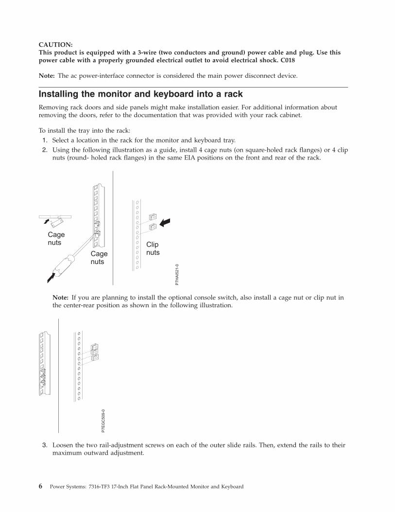
To install the tray into the rack:1. Select a location in the rack for the monitor and keyboard tray.2. Using the following illustration as a guide, install 4 cage nuts (on square-holed rack flanges) or 4 clip
nuts (round- holed rack flanges) in the same EIA positions on the front and rear of the rack.
Note: If you are planning to install the optional console switch, also install a cage nut or clip nut inthe center-rear position as shown in the following illustration.
3. Loosen the two rail-adjustment screws on each of the outer slide rails. Then, extend the rails to theirmaximum outward adjustment.
P7E
GC
509-0
6 Power Systems: 7316-TF3 17-Inch Flat Panel Rack-Mounted Monitor and Keyboard
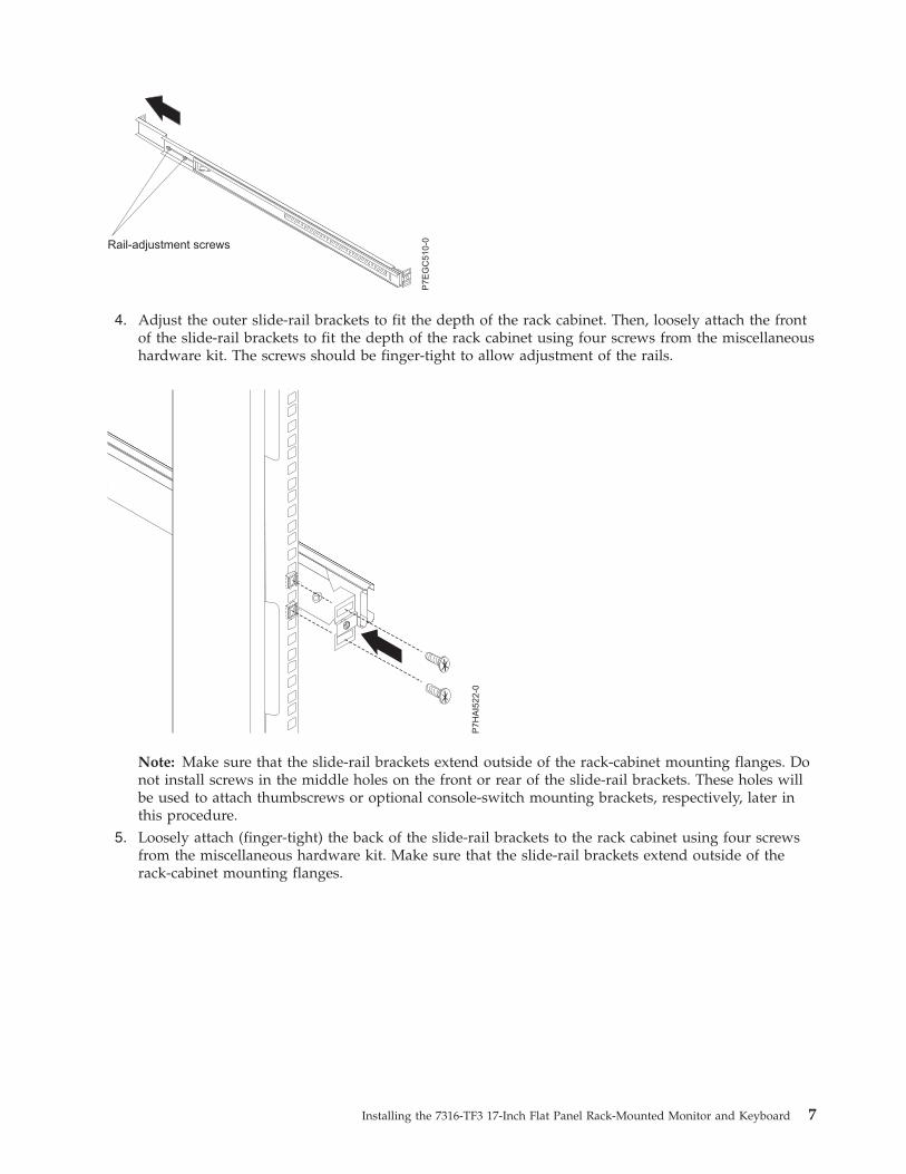
4. Adjust the outer slide-rail brackets to fit the depth of the rack cabinet. Then, loosely attach the frontof the slide-rail brackets to fit the depth of the rack cabinet using four screws from the miscellaneoushardware kit. The screws should be finger-tight to allow adjustment of the rails.
Note: Make sure that the slide-rail brackets extend outside of the rack-cabinet mounting flanges. Donot install screws in the middle holes on the front or rear of the slide-rail brackets. These holes willbe used to attach thumbscrews or optional console-switch mounting brackets, respectively, later inthis procedure.
5. Loosely attach (finger-tight) the back of the slide-rail brackets to the rack cabinet using four screwsfrom the miscellaneous hardware kit. Make sure that the slide-rail brackets extend outside of therack-cabinet mounting flanges.
Rail-adjustment screws
P7E
GC
510-0
Installing the 7316-TF3 17-Inch Flat Panel Rack-Mounted Monitor and Keyboard 7
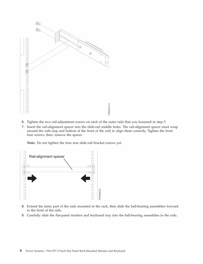
6. Tighten the two rail-adjustment screws on each of the outer rails that you loosened in step 57. Insert the rail-alignment spacer into the slide-rail middle holes. The rail-alignment spacer must wrap
around the rails (top and bottom of the front of the rail) to align them correctly. Tighten the frontfour screws; then, remove the spacer.
Note: Do not tighten the four rear slide-rail bracket screws yet.
8. Extend the inner part of the rails mounted in the rack, then slide the ball-bearing assemblies forwardto the front of the rails.
9. Carefully slide the flat-panel monitor and keyboard tray into the ball-bearing assemblies in the rails.
P7E
GC
511-0
8 Power Systems: 7316-TF3 17-Inch Flat Panel Rack-Mounted Monitor and Keyboard
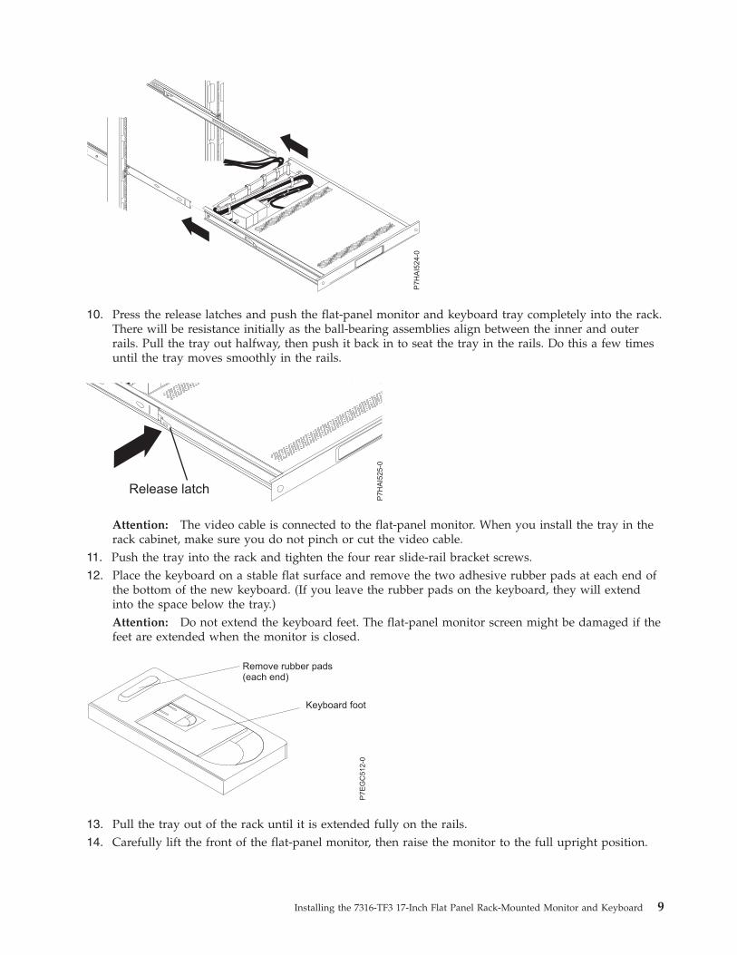
10. Press the release latches and push the flat-panel monitor and keyboard tray completely into the rack.There will be resistance initially as the ball-bearing assemblies align between the inner and outerrails. Pull the tray out halfway, then push it back in to seat the tray in the rails. Do this a few timesuntil the tray moves smoothly in the rails.
Attention: The video cable is connected to the flat-panel monitor. When you install the tray in therack cabinet, make sure you do not pinch or cut the video cable.
11. Push the tray into the rack and tighten the four rear slide-rail bracket screws.12. Place the keyboard on a stable flat surface and remove the two adhesive rubber pads at each end of
the bottom of the new keyboard. (If you leave the rubber pads on the keyboard, they will extendinto the space below the tray.)Attention: Do not extend the keyboard feet. The flat-panel monitor screen might be damaged if thefeet are extended when the monitor is closed.
13. Pull the tray out of the rack until it is extended fully on the rails.14. Carefully lift the front of the flat-panel monitor, then raise the monitor to the full upright position.
P7E
GC
512-0
Remove rubber pads(each end)
Keyboard foot
Installing the 7316-TF3 17-Inch Flat Panel Rack-Mounted Monitor and Keyboard 9
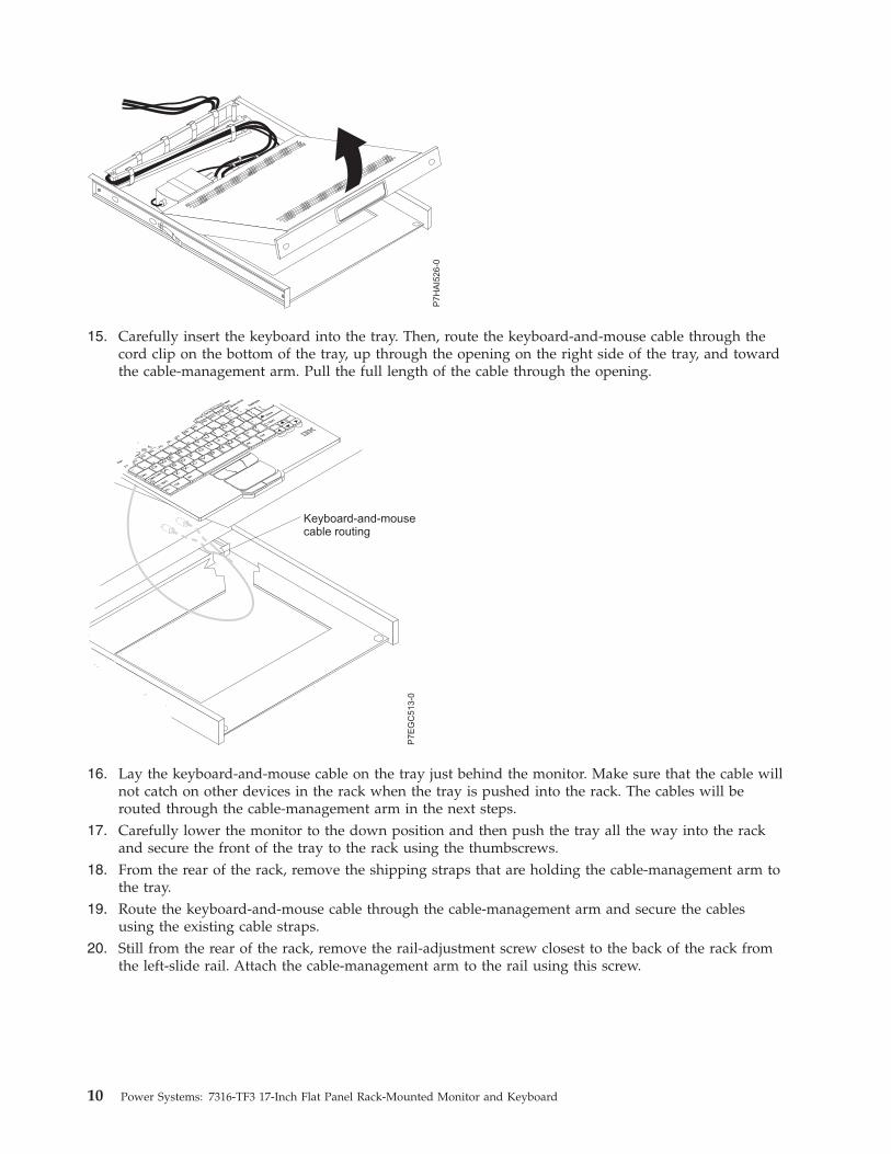
15. Carefully insert the keyboard into the tray. Then, route the keyboard-and-mouse cable through thecord clip on the bottom of the tray, up through the opening on the right side of the tray, and towardthe cable-management arm. Pull the full length of the cable through the opening.
16. Lay the keyboard-and-mouse cable on the tray just behind the monitor. Make sure that the cable willnot catch on other devices in the rack when the tray is pushed into the rack. The cables will berouted through the cable-management arm in the next steps.
17. Carefully lower the monitor to the down position and then push the tray all the way into the rackand secure the front of the tray to the rack using the thumbscrews.
18. From the rear of the rack, remove the shipping straps that are holding the cable-management arm tothe tray.
19. Route the keyboard-and-mouse cable through the cable-management arm and secure the cablesusing the existing cable straps.
20. Still from the rear of the rack, remove the rail-adjustment screw closest to the back of the rack fromthe left-slide rail. Attach the cable-management arm to the rail using this screw.
Keyboard-and-mousecable routing
Fn
Ctrl
Ctrl
Alt
Alt
AZ
SX
DC
FV
GB
HN
JM
K<
,
L>
.
:; ?
/
“‘
Enter
Shift
Shift
Caps
Lock
Esc
F1
F2
F3
F4
F5
F6
F7
F8
F9
F10
F11
F12
Delet
eInsert
PrtSc
End
ScrLk
Pause
1 Q
2 W
3 E
4 R
5 T
6 Y
7 U
8 I
9 O0 P
{[
}]
|\
Backspa
Tab
~`
_-
+=
P7E
GC
513-0
10 Power Systems: 7316-TF3 17-Inch Flat Panel Rack-Mounted Monitor and Keyboard
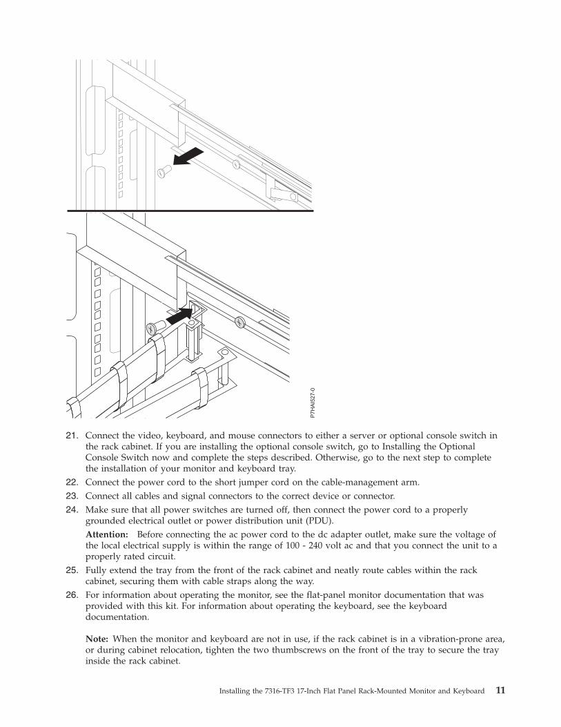
21. Connect the video, keyboard, and mouse connectors to either a server or optional console switch inthe rack cabinet. If you are installing the optional console switch, go to Installing the OptionalConsole Switch now and complete the steps described. Otherwise, go to the next step to completethe installation of your monitor and keyboard tray.
22. Connect the power cord to the short jumper cord on the cable-management arm.23. Connect all cables and signal connectors to the correct device or connector.24. Make sure that all power switches are turned off, then connect the power cord to a properly
grounded electrical outlet or power distribution unit (PDU).Attention: Before connecting the ac power cord to the dc adapter outlet, make sure the voltage ofthe local electrical supply is within the range of 100 - 240 volt ac and that you connect the unit to aproperly rated circuit.
25. Fully extend the tray from the front of the rack cabinet and neatly route cables within the rackcabinet, securing them with cable straps along the way.
26. For information about operating the monitor, see the flat-panel monitor documentation that wasprovided with this kit. For information about operating the keyboard, see the keyboarddocumentation.
Note: When the monitor and keyboard are not in use, if the rack cabinet is in a vibration-prone area,or during cabinet relocation, tighten the two thumbscrews on the front of the tray to secure the trayinside the rack cabinet.
Installing the 7316-TF3 17-Inch Flat Panel Rack-Mounted Monitor and Keyboard 11
Installing the Optional Console SwitchAttention: Before beginning, read “Safety Considerations”
You can use the console switch (Feature Code 4200 or 4202) to attach more than one server to a singlemonitor and keyboard. The console-switch option is available separately, but custom mounting bracketsfor the switch come with this kit.
By installing the console switch behind the monitor and keyboard tray, both can occupy the same spacein the rack. To install the console switch behind the tray, use the brackets provided with this kit.
Attention: The console switch will extend beyond the rear rack-mounting flanges when you install theswitch behind the tray.
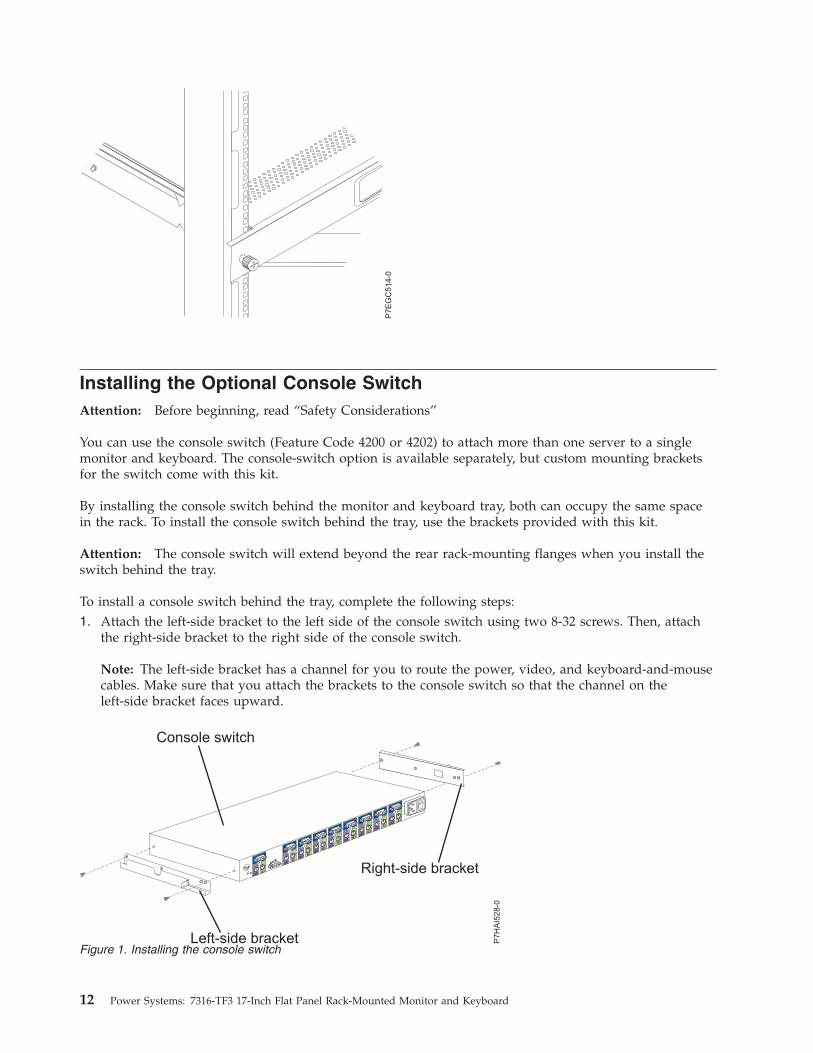
To install a console switch behind the tray, complete the following steps:1. Attach the left-side bracket to the left side of the console switch using two 8-32 screws. Then, attach
the right-side bracket to the right side of the console switch.
Note: The left-side bracket has a channel for you to route the power, video, and keyboard-and-mousecables. Make sure that you attach the brackets to the console switch so that the channel on theleft-side bracket faces upward.
P7E
GC
514-0
Figure 1. Installing the console switch
12 Power Systems: 7316-TF3 17-Inch Flat Panel Rack-Mounted Monitor and Keyboard
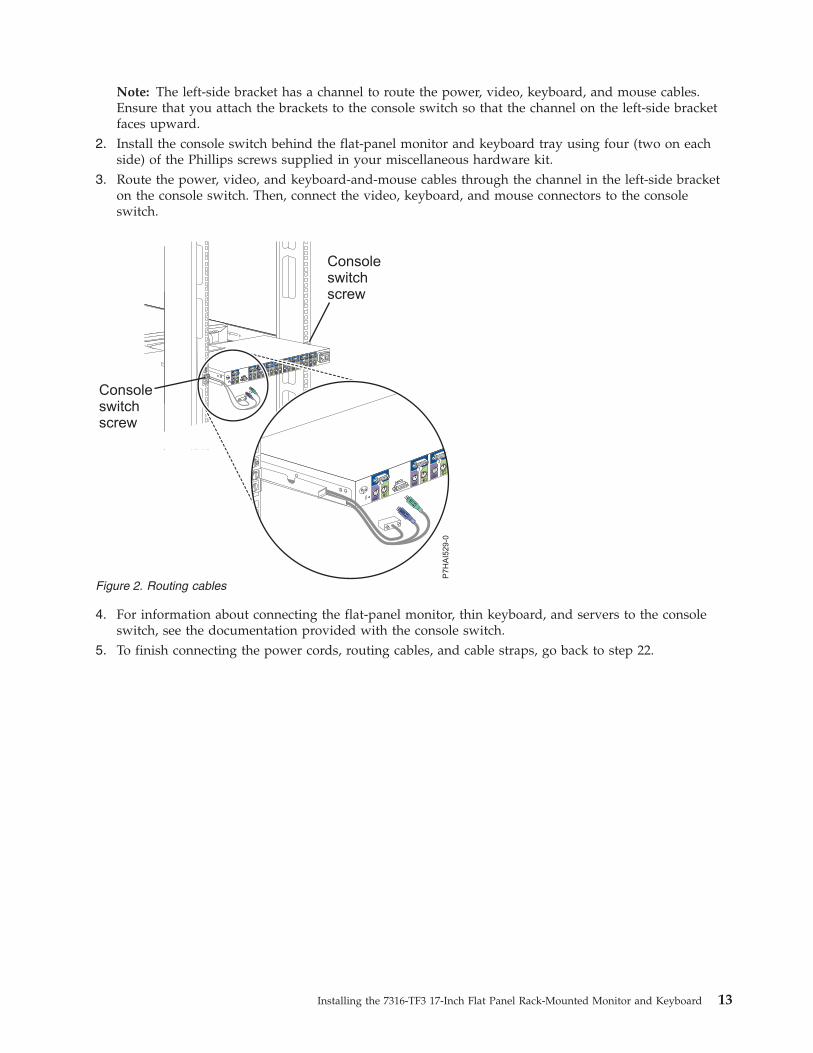
Note: The left-side bracket has a channel to route the power, video, keyboard, and mouse cables.Ensure that you attach the brackets to the console switch so that the channel on the left-side bracketfaces upward.
2. Install the console switch behind the flat-panel monitor and keyboard tray using four (two on eachside) of the Phillips screws supplied in your miscellaneous hardware kit.
3. Route the power, video, and keyboard-and-mouse cables through the channel in the left-side bracketon the console switch. Then, connect the video, keyboard, and mouse connectors to the consoleswitch.
4. For information about connecting the flat-panel monitor, thin keyboard, and servers to the consoleswitch, see the documentation provided with the console switch.
5. To finish connecting the power cords, routing cables, and cable straps, go back to step 22.
Figure 2. Routing cables
Installing the 7316-TF3 17-Inch Flat Panel Rack-Mounted Monitor and Keyboard 13

14 Power Systems: 7316-TF3 17-Inch Flat Panel Rack-Mounted Monitor and Keyboard
Using the Monitor
When using the monitor, observe the following basic guidelines:v Never insert anything metallic into the openings in the cabinet of the LCD monitor; doing so can create
the danger of electric shock.v To avoid electric shock, never open the LCD monitor case. The case should only be opened by trained
service personnel.v Never use your LCD monitor if the power cord has been damaged. Do not allow anything to rest on
the power cord or pinch the power cord.v Be sure to hold the plug, not the cord, when disconnecting the LCD monitor from an electric socket.v Openings in the LCD monitor case are provided for ventilation. To prevent overheating, these openings
should not be blocked or covered. Install the unit in a well-ventilated area.v Place your LCD monitor in a location with low humidity and a minimum amount of dust.v If the LCD monitor accidentally gets wet, unplug it and contact your IBM representative or reseller
immediately. You can clean the LCD monitor with a damp cloth when necessary, but be sure to unplugthe LCD monitor first.
v Place the LCD monitor on a solid surface and treat it carefully. The screen is made of thin glass with aplastic front surface and can be damaged if dropped, hit, or scratched. Do not clean the front panelwith ketone-type materials (for example, acetone), ethyl alcohol, toluene, ethyl acid, methyl, orchloride. These materials might damage the monitor.
v Locate your LCD monitor near an easily accessible ac outlet.v If there are any unusual sounds or smells coming from your LCD monitor, unplug it immediately and
contact your IBM representative or reseller.v High temperature can cause problems. Keep your LCD monitor away from direct sunlight, heaters, and
other sources of heat.v Unplug your LCD monitor when it is going to be left unused for an extended period of time.v Unplug your LCD monitor from the ac outlet before any service.v The maximum operating ambient temperature is 40°C.v Connect the mouse (touchpad, pointer) and keyboard only to listed Information Technology Equipment
(ITE) with Limited Power Source (LPS) keyboard and mouse (touchpad, pointer) outputs.
User ControlsThese controls available on the front of the monitor:
Auto Activates the auto adjustment function. The Auto adjustment is being processed message isdisplayed.
Exit Exits the OSD (On-screen display) function or returns to the previous menu.
Power IndicatorIndicates the status of monitor operation.
Green Normal
Black Power OFF
AmberPower saving mode or disconnection of signal cable
Power ButtonTurns on and off the monitor power.
© Copyright IBM Corp. 2004, 2013 15
t/u
v Moves the selector left and right on the OSD menuv Increases or deceases the value of the selected adjustment or selects the proper settingv Adjusts the brightness of the back light lamp by pressing the t or u buttons without the OSD
menu (Hot key)
Menu
v Opens the OSD menuv Selects the function to be adjustedv Moves the selector down on the OSD menu
Technical SpecificationsThe following highlighting conventions are used in this document:
LCD Panel
Size 17.0. Diagonal
Display area 337.92 (H) x 270.336 (V) mm
Type a-Si TFT active matrix
Pixel pitch 0.264 (H) x 0.264 (W) mm
Frequency
Horizontal 30 – 61 kHz Vertical 50 – 75 Hz
Display Color 16.7M Colors
Display Resolution
Optimum Mode 1280 x 1024 @ 60 Hz
Maximum Mode 1280 x 1024 @ 75 Hz
Input Signal
Sync HN Separate, TTL, Positive or Negative
Sync HN Composite, TTL, Positive or Negative
Sync-on-green 0.3 Vp-p, Negative
Video Signal 0.700 Vp-p @ 75 ohm, Positive
Power Supply
100-240 volt ac, 60 Hz – 50 Hz to 12V/ 3.75A
Power Consumption
Normal 20 Watts
Power Saving Less than 3 Watts
Environmental Considerations
Operating Temperature (0°C to 40°C)
Operating Humidity 10% to 80%
16 Power Systems: 7316-TF3 17-Inch Flat Panel Rack-Mounted Monitor and Keyboard
Storage Temperature (-25°C to 60°C)
Storage Humidity 5% to 95%
Using the Monitor 17

18 Power Systems: 7316-TF3 17-Inch Flat Panel Rack-Mounted Monitor and Keyboard
Hardware Maintenance Information
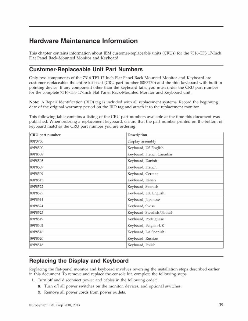
This chapter contains information about IBM customer-replaceable units (CRUs) for the 7316-TF3 17-InchFlat Panel Rack-Mounted Monitor and Keyboard.
Customer-Replaceable Unit Part NumbersOnly two components of the 7316-TF3 17-Inch Flat Panel Rack-Mounted Monitor and Keyboard arecustomer replaceable: the entire kit itself (CRU part number 80P3750) and the thin keyboard with built-inpointing device. If any component other than the keyboard fails, you must order the CRU part numberfor the complete 7316-TF3 17-Inch Flat Panel Rack-Mounted Monitor and Keyboard unit.
Note: A Repair Identification (RID) tag is included with all replacement systems. Record the beginningdate of the original warranty period on the RID tag and attach it to the replacement monitor.
This following table contains a listing of the CRU part numbers available at the time this document waspublished. When ordering a replacement keyboard, ensure that the part number printed on the bottom ofkeyboard matches the CRU part number you are ordering.
CRU part number Description
80P3750 Display assembly
89P8500 Keyboard, US English
89P8508 Keyboard, French Canadian
89P8505 Keyboard, Danish
89P8507 Keyboard, French
89P8509 Keyboard, German
89P8513 Keyboard, Italian
89P8522 Keyboard, Spanish
89P8527 Keyboard, UK English
89P8514 Keyboard, Japanese
89P8524 Keyboard, Swiss
89P8523 Keyboard, Swedish/Finnish
89P8519 Keyboard, Portuguese
89P8502 Keyboard, Belgian-UK
89P8516 Keyboard, LA Spanish
89P8520 Keyboard, Russian
89P8518 Keyboard, Polish
Replacing the Display and KeyboardReplacing the flat-panel monitor and keyboard involves reversing the installation steps described earlierin this document. To remove and replace the console kit, complete the following steps.1. Turn off and disconnect power and cables in the following order:
a. Turn off all power switches on the monitor, devices, and optional switches.b. Remove all power cords from power outlets.
© Copyright IBM Corp. 2004, 2013 19
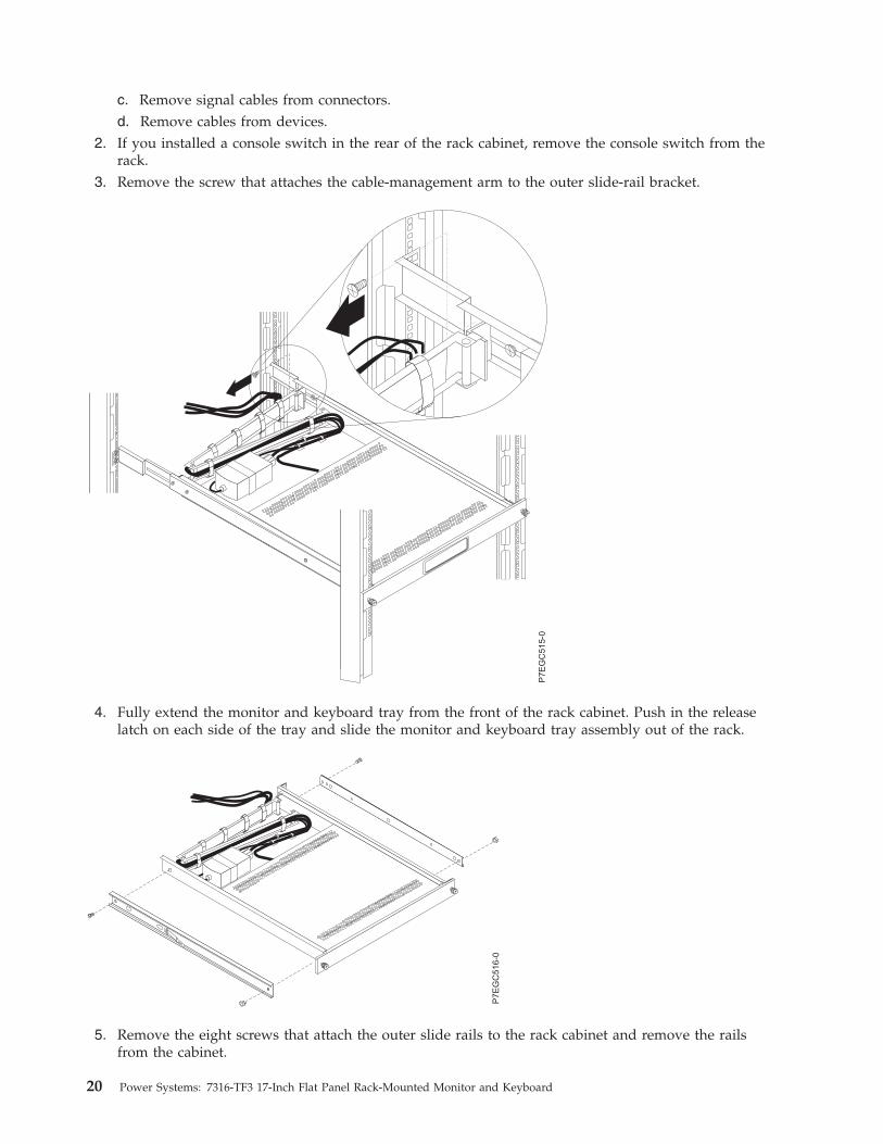
c. Remove signal cables from connectors.d. Remove cables from devices.
2. If you installed a console switch in the rear of the rack cabinet, remove the console switch from therack.
3. Remove the screw that attaches the cable-management arm to the outer slide-rail bracket.
4. Fully extend the monitor and keyboard tray from the front of the rack cabinet. Push in the releaselatch on each side of the tray and slide the monitor and keyboard tray assembly out of the rack.
5. Remove the eight screws that attach the outer slide rails to the rack cabinet and remove the railsfrom the cabinet.
P7E
GC
515-0
P7E
GC
516-0
20 Power Systems: 7316-TF3 17-Inch Flat Panel Rack-Mounted Monitor and Keyboard
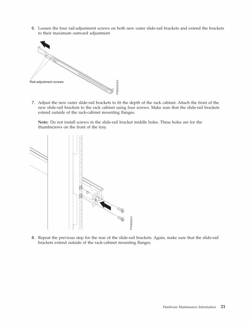
6. Loosen the four rail-adjustment screws on both new outer slide-rail brackets and extend the bracketsto their maximum outward adjustment.
7. Adjust the new outer slide-rail brackets to fit the depth of the rack cabinet. Attach the front of thenew slide-rail brackets to the rack cabinet using four screws. Make sure that the slide-rail bracketsextend outside of the rack-cabinet mounting flanges.
Note: Do not install screws in the slide-rail bracket middle holes. These holes are for thethumbscrews on the front of the tray.
8. Repeat the previous step for the rear of the slide-rail brackets. Again, make sure that the slide-railbrackets extend outside of the rack-cabinet mounting flanges.
Rail-adjustment screws
P7E
GC
510-0
Hardware Maintenance Information 21
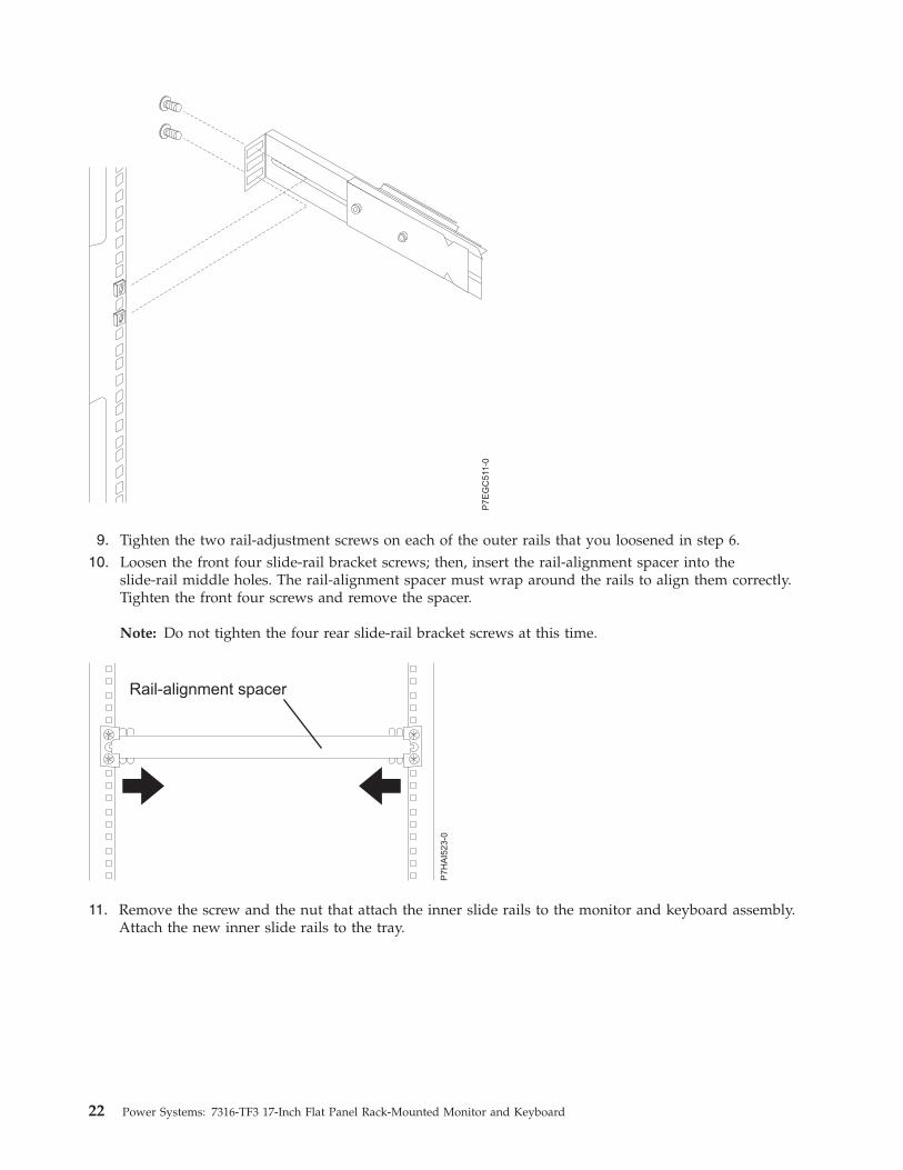
9. Tighten the two rail-adjustment screws on each of the outer rails that you loosened in step 6.10. Loosen the front four slide-rail bracket screws; then, insert the rail-alignment spacer into the
slide-rail middle holes. The rail-alignment spacer must wrap around the rails to align them correctly.Tighten the front four screws and remove the spacer.
Note: Do not tighten the four rear slide-rail bracket screws at this time.
11. Remove the screw and the nut that attach the inner slide rails to the monitor and keyboard assembly.Attach the new inner slide rails to the tray.
P7E
GC
511-0
22 Power Systems: 7316-TF3 17-Inch Flat Panel Rack-Mounted Monitor and Keyboard
12. For instructions on reinstalling the monitor and keyboard tray in the rack cabinet, go to “Installingthe Monitor and Keyboard Tray into a Rack”.
13. Install any other devices that you removed from the rack cabinet.
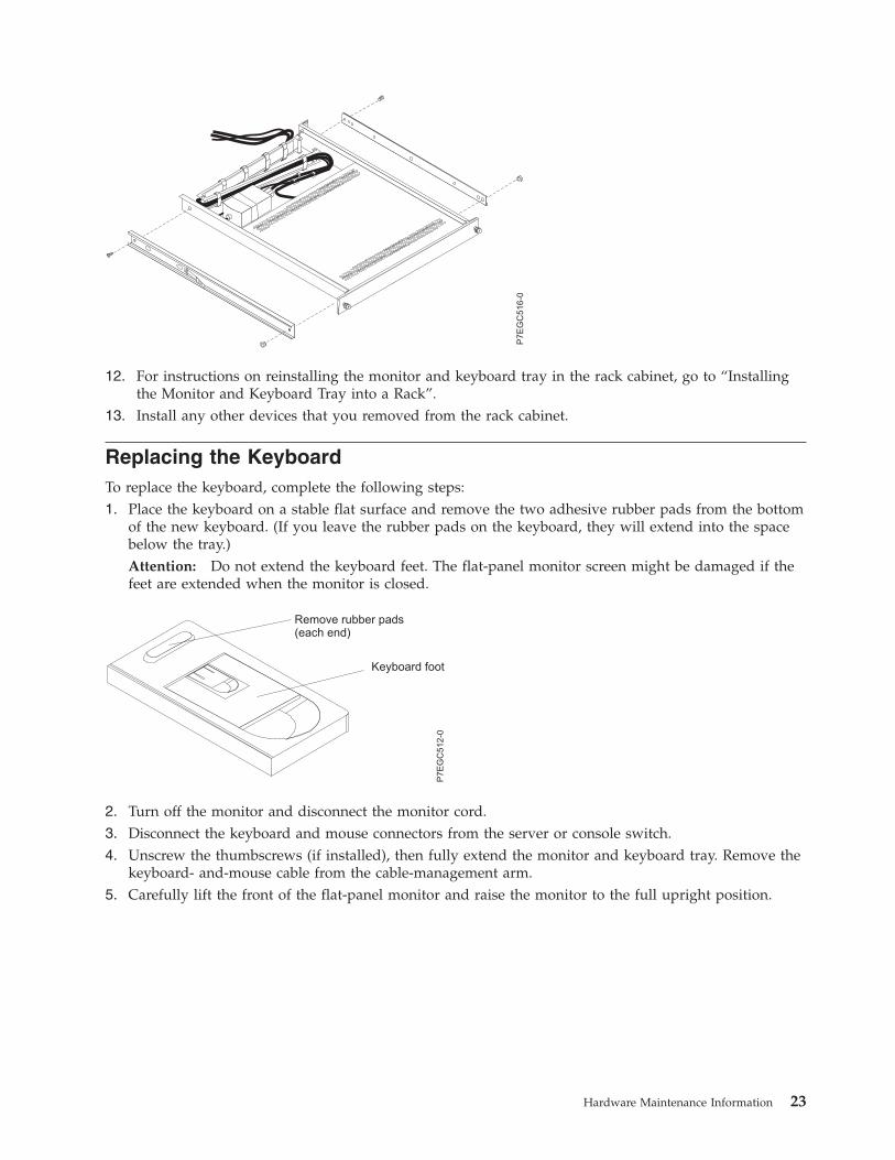
Replacing the KeyboardTo replace the keyboard, complete the following steps:1. Place the keyboard on a stable flat surface and remove the two adhesive rubber pads from the bottom
of the new keyboard. (If you leave the rubber pads on the keyboard, they will extend into the spacebelow the tray.)Attention: Do not extend the keyboard feet. The flat-panel monitor screen might be damaged if thefeet are extended when the monitor is closed.
2. Turn off the monitor and disconnect the monitor cord.3. Disconnect the keyboard and mouse connectors from the server or console switch.4. Unscrew the thumbscrews (if installed), then fully extend the monitor and keyboard tray. Remove the
keyboard- and-mouse cable from the cable-management arm.5. Carefully lift the front of the flat-panel monitor and raise the monitor to the full upright position.
P7E
GC
516-0
P7E
GC
512-0
Remove rubber pads(each end)
Keyboard foot
Hardware Maintenance Information 23
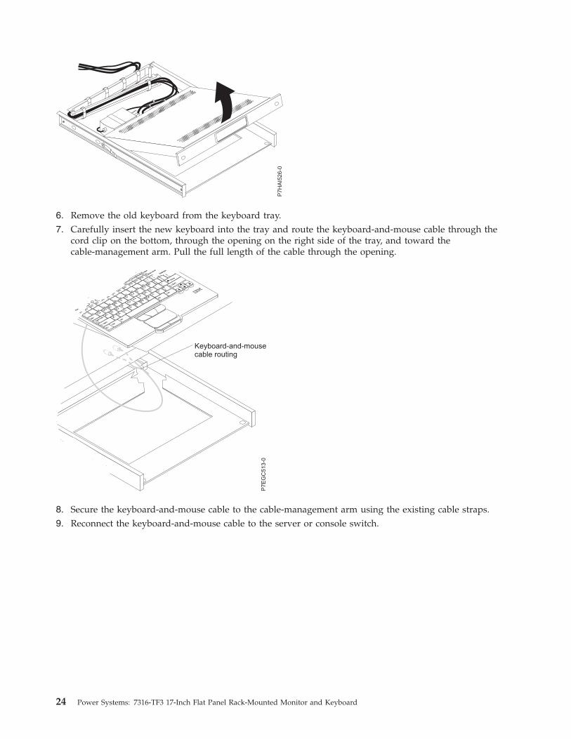
6. Remove the old keyboard from the keyboard tray.7. Carefully insert the new keyboard into the tray and route the keyboard-and-mouse cable through the
cord clip on the bottom, through the opening on the right side of the tray, and toward thecable-management arm. Pull the full length of the cable through the opening.
8. Secure the keyboard-and-mouse cable to the cable-management arm using the existing cable straps.9. Reconnect the keyboard-and-mouse cable to the server or console switch.
Keyboard-and-mousecable routing
Fn
Ctrl
Ctrl
Alt
Alt
AZ
SX
DC
FV
GB
HN
JM
K<
,
L>
.
:; ?
/
“‘
Enter
Shift
Shift
Caps
Lock
Esc
F1
F2
F3
F4
F5
F6
F7
F8
F9
F10
F11
F12
Delet
eInsert
PrtSc
End
ScrLk
Pause
1 Q
2 W
3 E
4 R
5 T
6 Y
7 U
8 I
9 O0 P
{[
}]
|\
Backspa
Tab
~`
_-
+=
P7E
GC
513-0
24 Power Systems: 7316-TF3 17-Inch Flat Panel Rack-Mounted Monitor and Keyboard
Notices
This information was developed for products and services offered in the U.S.A.
The manufacturer may not offer the products, services, or features discussed in this document in othercountries. Consult the manufacturer's representative for information on the products and servicescurrently available in your area. Any reference to the manufacturer's product, program, or service is notintended to state or imply that only that product, program, or service may be used. Any functionallyequivalent product, program, or service that does not infringe any intellectual property right of themanufacturer may be used instead. However, it is the user's responsibility to evaluate and verify theoperation of any product, program, or service.
The manufacturer may have patents or pending patent applications covering subject matter described inthis document. The furnishing of this document does not grant you any license to these patents. You cansend license inquiries, in writing, to the manufacturer.
The following paragraph does not apply to the United Kingdom or any other country where suchprovisions are inconsistent with local law: THIS PUBLICATION IS PROVIDED “AS IS” WITHOUTWARRANTY OF ANY KIND, EITHER EXPRESS OR IMPLIED, INCLUDING, BUT NOT LIMITED TO,THE IMPLIED WARRANTIES OF NON-INFRINGEMENT, MERCHANTABILITY OR FITNESS FOR APARTICULAR PURPOSE. Some states do not allow disclaimer of express or implied warranties in certaintransactions, therefore, this statement may not apply to you.
This information could include technical inaccuracies or typographical errors. Changes are periodicallymade to the information herein; these changes will be incorporated in new editions of the publication.The manufacturer may make improvements and/or changes in the product(s) and/or the program(s)described in this publication at any time without notice.
Any references in this information to websites not owned by the manufacturer are provided forconvenience only and do not in any manner serve as an endorsement of those websites. The materials atthose websites are not part of the materials for this product and use of those websites is at your own risk.
The manufacturer may use or distribute any of the information you supply in any way it believesappropriate without incurring any obligation to you.
Any performance data contained herein was determined in a controlled environment. Therefore, theresults obtained in other operating environments may vary significantly. Some measurements may havebeen made on development-level systems and there is no guarantee that these measurements will be thesame on generally available systems. Furthermore, some measurements may have been estimated throughextrapolation. Actual results may vary. Users of this document should verify the applicable data for theirspecific environment.
Information concerning products not produced by this manufacturer was obtained from the suppliers ofthose products, their published announcements or other publicly available sources. This manufacturer hasnot tested those products and cannot confirm the accuracy of performance, compatibility or any otherclaims related to products not produced by this manufacturer. Questions on the capabilities of productsnot produced by this manufacturer should be addressed to the suppliers of those products.
All statements regarding the manufacturer's future direction or intent are subject to change or withdrawalwithout notice, and represent goals and objectives only.
The manufacturer's prices shown are the manufacturer's suggested retail prices, are current and aresubject to change without notice. Dealer prices may vary.
© Copyright IBM Corp. 2004, 2013 25
This information is for planning purposes only. The information herein is subject to change before theproducts described become available.
This information contains examples of data and reports used in daily business operations. To illustratethem as completely as possible, the examples include the names of individuals, companies, brands, andproducts. All of these names are fictitious and any similarity to the names and addresses used by anactual business enterprise is entirely coincidental.
If you are viewing this information in softcopy, the photographs and color illustrations may not appear.
The drawings and specifications contained herein shall not be reproduced in whole or in part without thewritten permission of the manufacturer.
The manufacturer has prepared this information for use with the specific machines indicated. Themanufacturer makes no representations that it is suitable for any other purpose.
The manufacturer's computer systems contain mechanisms designed to reduce the possibility ofundetected data corruption or loss. This risk, however, cannot be eliminated. Users who experienceunplanned outages, system failures, power fluctuations or outages, or component failures must verify theaccuracy of operations performed and data saved or transmitted by the system at or near the time of theoutage or failure. In addition, users must establish procedures to ensure that there is independent dataverification before relying on such data in sensitive or critical operations. Users should periodically checkthe manufacturer's support websites for updated information and fixes applicable to the system andrelated software.
Homologation statement
This product may not be certified in your country for connection by any means whatsoever to interfacesof public telecommunications networks. Further certification may be required by law prior to making anysuch connection. Contact an IBM representative or reseller for any questions.
TrademarksIBM, the IBM logo, and ibm.com are trademarks or registered trademarks of International BusinessMachines Corp., registered in many jurisdictions worldwide. Other product and service names might betrademarks of IBM or other companies. A current list of IBM trademarks is available on the web atCopyright and trademark information at www.ibm.com/legal/copytrade.shtml.
Microsoft and Windows are trademarks of Microsoft Corporation in the United States, other countries, orboth.
Electronic emission noticesWhen attaching a monitor to the equipment, you must use the designated monitor cable and anyinterference suppression devices supplied with the monitor.
Class A NoticesThe following Class A statements apply to the IBM servers that contain the POWER7® processor and itsfeatures unless designated as electromagnetic compatibility (EMC) Class B in the feature information.
Federal Communications Commission (FCC) statement
Note: This equipment has been tested and found to comply with the limits for a Class A digital device,pursuant to Part 15 of the FCC Rules. These limits are designed to provide reasonable protection againstharmful interference when the equipment is operated in a commercial environment. This equipment
26 Power Systems: 7316-TF3 17-Inch Flat Panel Rack-Mounted Monitor and Keyboard

generates, uses, and can radiate radio frequency energy and, if not installed and used in accordance withthe instruction manual, may cause harmful interference to radio communications. Operation of thisequipment in a residential area is likely to cause harmful interference, in which case the user will berequired to correct the interference at his own expense.
Properly shielded and grounded cables and connectors must be used in order to meet FCC emissionlimits. IBM is not responsible for any radio or television interference caused by using other thanrecommended cables and connectors or by unauthorized changes or modifications to this equipment.Unauthorized changes or modifications could void the user's authority to operate the equipment.
This device complies with Part 15 of the FCC rules. Operation is subject to the following two conditions:(1) this device may not cause harmful interference, and (2) this device must accept any interferencereceived, including interference that may cause undesired operation.
Industry Canada Compliance Statement
This Class A digital apparatus complies with Canadian ICES-003.
Avis de conformité à la réglementation d'Industrie Canada
Cet appareil numérique de la classe A est conforme à la norme NMB-003 du Canada.
European Community Compliance Statement
This product is in conformity with the protection requirements of EU Council Directive 2004/108/EC onthe approximation of the laws of the Member States relating to electromagnetic compatibility. IBM cannotaccept responsibility for any failure to satisfy the protection requirements resulting from anon-recommended modification of the product, including the fitting of non-IBM option cards.
This product has been tested and found to comply with the limits for Class A Information TechnologyEquipment according to European Standard EN 55022. The limits for Class A equipment were derived forcommercial and industrial environments to provide reasonable protection against interference withlicensed communication equipment.
European Community contact:IBM Deutschland GmbHTechnical Regulations, Department M372IBM-Allee 1, 71139 Ehningen, GermanyTele: +49 7032 15 2941email: [email protected]
Warning: This is a Class A product. In a domestic environment, this product may cause radiointerference, in which case the user may be required to take adequate measures.
VCCI Statement - Japan
The following is a summary of the VCCI Japanese statement in the box above:
Notices 27
This is a Class A product based on the standard of the VCCI Council. If this equipment is used in adomestic environment, radio interference may occur, in which case, the user may be required to takecorrective actions.
Japanese Electronics and Information Technology Industries Association (JEITA)Confirmed Harmonics Guideline (products less than or equal to 20 A per phase)
Japanese Electronics and Information Technology Industries Association (JEITA)Confirmed Harmonics Guideline with Modifications (products greater than 20 A perphase)
Electromagnetic Interference (EMI) Statement - People's Republic of China
Declaration: This is a Class A product. In a domestic environment this product may cause radiointerference in which case the user may need to perform practical action.
Electromagnetic Interference (EMI) Statement - Taiwan
The following is a summary of the EMI Taiwan statement above.
Warning: This is a Class A product. In a domestic environment this product may cause radio interferencein which case the user will be required to take adequate measures.
IBM Taiwan Contact Information:
28 Power Systems: 7316-TF3 17-Inch Flat Panel Rack-Mounted Monitor and Keyboard
Electromagnetic Interference (EMI) Statement - Korea
Germany Compliance Statement
Deutschsprachiger EU Hinweis: Hinweis für Geräte der Klasse A EU-Richtlinie zurElektromagnetischen Verträglichkeit
Dieses Produkt entspricht den Schutzanforderungen der EU-Richtlinie 2004/108/EG zur Angleichung derRechtsvorschriften über die elektromagnetische Verträglichkeit in den EU-Mitgliedsstaaten und hält dieGrenzwerte der EN 55022 Klasse A ein.
Um dieses sicherzustellen, sind die Geräte wie in den Handbüchern beschrieben zu installieren und zubetreiben. Des Weiteren dürfen auch nur von der IBM empfohlene Kabel angeschlossen werden. IBMübernimmt keine Verantwortung für die Einhaltung der Schutzanforderungen, wenn das Produkt ohneZustimmung von IBM verändert bzw. wenn Erweiterungskomponenten von Fremdherstellern ohneEmpfehlung von IBM gesteckt/eingebaut werden.
EN 55022 Klasse A Geräte müssen mit folgendem Warnhinweis versehen werden:"Warnung: Dieses ist eine Einrichtung der Klasse A. Diese Einrichtung kann im WohnbereichFunk-Störungen verursachen; in diesem Fall kann vom Betreiber verlangt werden, angemesseneMaßnahmen zu ergreifen und dafür aufzukommen."
Deutschland: Einhaltung des Gesetzes über die elektromagnetische Verträglichkeit von Geräten
Dieses Produkt entspricht dem “Gesetz über die elektromagnetische Verträglichkeit von Geräten(EMVG)“. Dies ist die Umsetzung der EU-Richtlinie 2004/108/EG in der Bundesrepublik Deutschland.
Zulassungsbescheinigung laut dem Deutschen Gesetz über die elektromagnetische Verträglichkeit vonGeräten (EMVG) (bzw. der EMC EG Richtlinie 2004/108/EG) für Geräte der Klasse A
Dieses Gerät ist berechtigt, in Übereinstimmung mit dem Deutschen EMVG das EG-Konformitätszeichen- CE - zu führen.
Notices 29
Verantwortlich für die Einhaltung der EMV Vorschriften ist der Hersteller:International Business Machines Corp.New Orchard RoadArmonk, New York 10504Tel: 914-499-1900
Der verantwortliche Ansprechpartner des Herstellers in der EU ist:IBM Deutschland GmbHTechnical Regulations, Abteilung M372IBM-Allee 1, 71139 Ehningen, GermanyTel: +49 7032 15 2941email: [email protected]
Generelle Informationen:
Das Gerät erfüllt die Schutzanforderungen nach EN 55024 und EN 55022 Klasse A.
Electromagnetic Interference (EMI) Statement - Russia
Class B NoticesThe following Class B statements apply to features designated as electromagnetic compatibility (EMC)Class B in the feature installation information.
Federal Communications Commission (FCC) statement
This equipment has been tested and found to comply with the limits for a Class B digital device,pursuant to Part 15 of the FCC Rules. These limits are designed to provide reasonable protection againstharmful interference in a residential installation.
This equipment generates, uses, and can radiate radio frequency energy and, if not installed and used inaccordance with the instructions, may cause harmful interference to radio communications. However,there is no guarantee that interference will not occur in a particular installation.
If this equipment does cause harmful interference to radio or television reception, which can bedetermined by turning the equipment off and on, the user is encouraged to try to correct the interferenceby one or more of the following measures:v Reorient or relocate the receiving antenna.v Increase the separation between the equipment and receiver.v Connect the equipment into an outlet on a circuit different from that to which the receiver is
connected.v Consult an IBM-authorized dealer or service representative for help.
Properly shielded and grounded cables and connectors must be used in order to meet FCC emissionlimits. Proper cables and connectors are available from IBM-authorized dealers. IBM is not responsible for
30 Power Systems: 7316-TF3 17-Inch Flat Panel Rack-Mounted Monitor and Keyboard

any radio or television interference caused by unauthorized changes or modifications to this equipment.Unauthorized changes or modifications could void the user's authority to operate this equipment.
This device complies with Part 15 of the FCC rules. Operation is subject to the following two conditions:(1) this device may not cause harmful interference, and (2) this device must accept any interferencereceived, including interference that may cause undesired operation.
Industry Canada Compliance Statement
This Class B digital apparatus complies with Canadian ICES-003.
Avis de conformité à la réglementation d'Industrie Canada
Cet appareil numérique de la classe B est conforme à la norme NMB-003 du Canada.
European Community Compliance Statement
This product is in conformity with the protection requirements of EU Council Directive 2004/108/EC onthe approximation of the laws of the Member States relating to electromagnetic compatibility. IBM cannotaccept responsibility for any failure to satisfy the protection requirements resulting from anon-recommended modification of the product, including the fitting of non-IBM option cards.
This product has been tested and found to comply with the limits for Class B Information TechnologyEquipment according to European Standard EN 55022. The limits for Class B equipment were derived fortypical residential environments to provide reasonable protection against interference with licensedcommunication equipment.
European Community contact:IBM Deutschland GmbHTechnical Regulations, Department M372IBM-Allee 1, 71139 Ehningen, GermanyTele: +49 7032 15 2941email: [email protected]
VCCI Statement - Japan
Japanese Electronics and Information Technology Industries Association (JEITA)Confirmed Harmonics Guideline (products less than or equal to 20 A per phase)
Notices 31
Japanese Electronics and Information Technology Industries Association (JEITA)Confirmed Harmonics Guideline with Modifications (products greater than 20 A perphase)
IBM Taiwan Contact Information
Electromagnetic Interference (EMI) Statement - Korea
Germany Compliance Statement
Deutschsprachiger EU Hinweis: Hinweis für Geräte der Klasse B EU-Richtlinie zurElektromagnetischen Verträglichkeit
Dieses Produkt entspricht den Schutzanforderungen der EU-Richtlinie 2004/108/EG zur Angleichung derRechtsvorschriften über die elektromagnetische Verträglichkeit in den EU-Mitgliedsstaaten und hält dieGrenzwerte der EN 55022 Klasse B ein.
Um dieses sicherzustellen, sind die Geräte wie in den Handbüchern beschrieben zu installieren und zubetreiben. Des Weiteren dürfen auch nur von der IBM empfohlene Kabel angeschlossen werden. IBMübernimmt keine Verantwortung für die Einhaltung der Schutzanforderungen, wenn das Produkt ohneZustimmung von IBM verändert bzw. wenn Erweiterungskomponenten von Fremdherstellern ohneEmpfehlung von IBM gesteckt/eingebaut werden.
Deutschland: Einhaltung des Gesetzes über die elektromagnetische Verträglichkeit von Geräten
Dieses Produkt entspricht dem “Gesetz über die elektromagnetische Verträglichkeit von Geräten(EMVG)“. Dies ist die Umsetzung der EU-Richtlinie 2004/108/EG in der Bundesrepublik Deutschland.
Zulassungsbescheinigung laut dem Deutschen Gesetz über die elektromagnetische Verträglichkeit vonGeräten (EMVG) (bzw. der EMC EG Richtlinie 2004/108/EG) für Geräte der Klasse B
32 Power Systems: 7316-TF3 17-Inch Flat Panel Rack-Mounted Monitor and Keyboard
Dieses Gerät ist berechtigt, in Übereinstimmung mit dem Deutschen EMVG das EG-Konformitätszeichen- CE - zu führen.
Verantwortlich für die Einhaltung der EMV Vorschriften ist der Hersteller:International Business Machines Corp.New Orchard RoadArmonk, New York 10504Tel: 914-499-1900
Der verantwortliche Ansprechpartner des Herstellers in der EU ist:IBM Deutschland GmbHTechnical Regulations, Abteilung M372IBM-Allee 1, 71139 Ehningen, GermanyTel: +49 7032 15 2941email: [email protected]
Generelle Informationen:
Das Gerät erfüllt die Schutzanforderungen nach EN 55024 und EN 55022 Klasse B.
Terms and conditionsPermissions for the use of these publications are granted subject to the following terms and conditions.
Applicability: These terms and conditions are in addition to any terms of use for the IBM website.
Personal Use: You may reproduce these publications for your personal, noncommercial use provided thatall proprietary notices are preserved. You may not distribute, display or make derivative works of thesepublications, or any portion thereof, without the express consent of IBM.
Commercial Use: You may reproduce, distribute and display these publications solely within yourenterprise provided that all proprietary notices are preserved. You may not make derivative works ofthese publications, or reproduce, distribute or display these publications or any portion thereof outsideyour enterprise, without the express consent of IBM.
Rights: Except as expressly granted in this permission, no other permissions, licenses or rights aregranted, either express or implied, to the Publications or any information, data, software or otherintellectual property contained therein.
IBM reserves the right to withdraw the permissions granted herein whenever, in its discretion, the use ofthe publications is detrimental to its interest or, as determined by IBM, the above instructions are notbeing properly followed.
You may not download, export or re-export this information except in full compliance with all applicablelaws and regulations, including all United States export laws and regulations.
IBM MAKES NO GUARANTEE ABOUT THE CONTENT OF THESE PUBLICATIONS. THEPUBLICATIONS ARE PROVIDED "AS-IS" AND WITHOUT WARRANTY OF ANY KIND, EITHEREXPRESSED OR IMPLIED, INCLUDING BUT NOT LIMITED TO IMPLIED WARRANTIES OFMERCHANTABILITY, NON-INFRINGEMENT, AND FITNESS FOR A PARTICULAR PURPOSE.
Notices 33

34 Power Systems: 7316-TF3 17-Inch Flat Panel Rack-Mounted Monitor and Keyboard

����
Part Number: 00LA009
Printed in USA
SA38-0643-01
(1P)
P/N:
00LA
009


![TF3 (user manual) - TME · alarm /] ℃/℉](https://img.pdfslide.us/doc/110x75/60d7d93d3e3716595072bb0f/tf3-user-manual-tme-alarm-afa.jpg)