Embed Size (px)
Citation preview
International Research Journal of Engineering and Technology (IRJET) e-ISSN: 2395 -0056
Volume: 04 Issue: 05 | May -2017 www.irjet.net p-ISSN: 2395-0072
© 2017, IRJET | Impact Factor value: 5.181 | ISO 9001:2008 Certified Journal | Page 1107
Power System Stability Enhancement By UPFC Based Power Oscillation Damping Controller
Mr. Santosh Kumar Tripathi
Associate Professor, Department of Electrical Engineering, B.N. College of Engineering & Technology, Lucknow,
Uttar Pradesh, India --------------------------------------------------------------------***---------------------------------------------------------------------
Abstract - This paper presents design and analysis of UPFC based power oscillation damping controller. The Phillips- Heffron model of the Single Machine Infinite Bus power system installed with UPFC has been used. The systematic approach for designing UPFC based power oscillation damping controller has been developed. The POD controller places the Eigen value corresponding to mode of oscillation at desired location so that the system has desired degree of stability. The performance of UPFC based POD controller has been examined with different system conditions, under different line loadings of SMIB power system. The effectiveness of proposed controller is verified by time domain simulation results in MAT-LAB environment.
Key Words: FACTS UPFC, Phillips–Heffron model, POD controller and SMIB.
1. INTRODUCTION Today’s power system is a complex network, sometimes made of thousands of buses and hundreds of generators. Available power generation usually does not situated near a growing of load center. In order to meet the growing power demand, utilities have an interest in better utilization of available power system capacities, existing generation and existing power transmission network, instead of building new transmission lines and expanding substations. On the other hand, power flows in some of the transmission lines are overloaded, which has as an overall effect of deteriorating voltage profiles and decreasing system stability and security. In addition, existing traditional transmission facilities, in most cases, are not designed to handle the control requirements of complex and highly interconnected power systems. This overall situation requires the review of traditional transmission methods and practices, and the creation of new concepts, which would allow the use of existing generation and transmission lines up to their full capabilities without reduction in system stability and security. In the past, power systems could not be controlled fast enough to handle dynamic system condition. This problem was solved by over-design; transmission systems were designed with generous stability margins to recover from anticipated operating contingencies caused by faults, line and generator outages, and equipment failures. Series capacitor, shunt capacitor, and phase shifter are different approaches to increase the power system transmission lines load ability. In past days, all these devices
are controlled and switched mechanically and were, therefore, relative slow. They are very useful in a steady state operation of power systems but from a dynamical point of view, their time response is too slow to effectively damp transient oscillations. If mechanically controlled systems were made to respond faster, power system security would be significantly improved, allowing the full utilization of system capability while maintaining adequate levels of stability. This concept and advances in the field of power electronics led to a new approach introduced by the Electric Power Research Institute (EPRI) in the late 1980. Called Flexible AC Transmission Systems or simply FACTS, it was an answer to a call for a more efficient use of already existing resources in present power systems while maintaining and even improving power system security. In order to clearly determine the goals of this thesis, the concept of “stability” must be defined. A definition given in [1] is as follows: “Power system stability may be broadly defined as that property of a power system that enables it to remain in a state of operating equilibrium under normal operating conditions and to regain an acceptable state of equilibrium after being subjected to a disturbance.” From this general definition, two categories of stability are derived: small-signal and transient stability. Small-signal stability is the ability of the system to return to a normal operating state following a small disturbance. Investigations involving this stability concept usually involve the analysis of the linearized state space equations that define the power system dynamics. Transient stability is the ability of the system to return to a normal operating state following a severe disturbance, such as a single or multi-phase short-circuit or a generator loss. Under these conditions, the linearized power system model does not usually apply and the nonlinear equations must be used directly for the analysis, and must be solved by direct methods or by iterative step-by-step procedures [2].Since the development of interconnection of large electric power systems, there have been spontaneous system oscillations at very low frequencies in order of 0.2-3.0Hz. Once started, the oscillation would continue for a while and then disappear, or continue to grow, causing system separation [3]. In order to damp these power system oscillations and increase system oscillations stability, the installation of Power System Stabilizer (PSS) is both economical and effective. PSSs have been used for many years to add damping to electromechanical oscillations. To date, most major electric
International Research Journal of Engineering and Technology (IRJET) e-ISSN: 2395 -0056
Volume: 04 Issue: 05 | May -2017 www.irjet.net p-ISSN: 2395-0072
© 2017, IRJET | Impact Factor value: 5.181 | ISO 9001:2008 Certified Journal | Page 1108
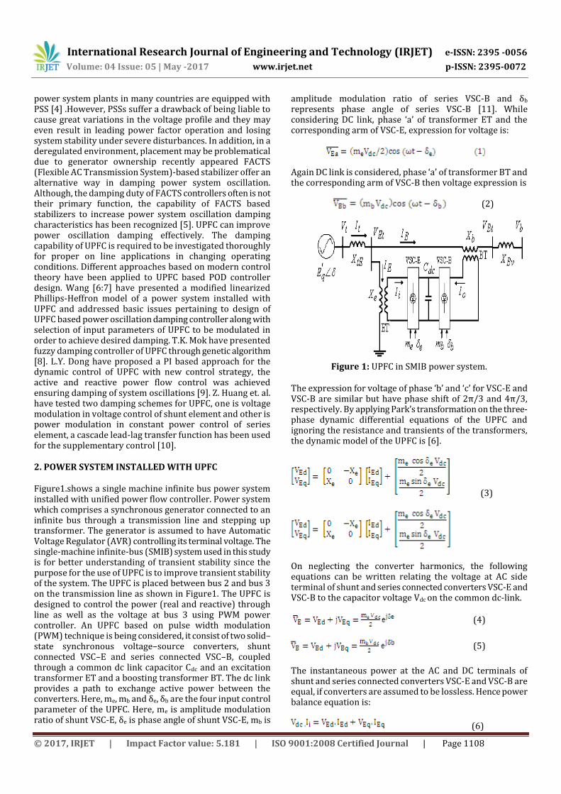
power system plants in many countries are equipped with PSS [4] .However, PSSs suffer a drawback of being liable to cause great variations in the voltage profile and they may even result in leading power factor operation and losing system stability under severe disturbances. In addition, in a deregulated environment, placement may be problematical due to generator ownership recently appeared FACTS (Flexible AC Transmission System)-based stabilizer offer an alternative way in damping power system oscillation. Although, the damping duty of FACTS controllers often is not their primary function, the capability of FACTS based stabilizers to increase power system oscillation damping characteristics has been recognized [5]. UPFC can improve power oscillation damping effectively. The damping capability of UPFC is required to be investigated thoroughly for proper on line applications in changing operating conditions. Different approaches based on modern control theory have been applied to UPFC based POD controller design. Wang [6:7] have presented a modified linearized Phillips-Heffron model of a power system installed with UPFC and addressed basic issues pertaining to design of UPFC based power oscillation damping controller along with selection of input parameters of UPFC to be modulated in order to achieve desired damping. T.K. Mok have presented fuzzy damping controller of UPFC through genetic algorithm [8]. L.Y. Dong have proposed a PI based approach for the dynamic control of UPFC with new control strategy, the active and reactive power flow control was achieved ensuring damping of system oscillations [9]. Z. Huang et. al. have tested two damping schemes for UPFC, one is voltage modulation in voltage control of shunt element and other is power modulation in constant power control of series element, a cascade lead-lag transfer function has been used for the supplementary control [10]. 2. POWER SYSTEM INSTALLED WITH UPFC Figure1.shows a single machine infinite bus power system installed with unified power flow controller. Power system which comprises a synchronous generator connected to an infinite bus through a transmission line and stepping up transformer. The generator is assumed to have Automatic Voltage Regulator (AVR) controlling its terminal voltage. The single-machine infinite-bus (SMIB) system used in this study is for better understanding of transient stability since the purpose for the use of UPFC is to improve transient stability of the system. The UPFC is placed between bus 2 and bus 3 on the transmission line as shown in Figure1. The UPFC is designed to control the power (real and reactive) through line as well as the voltage at bus 3 using PWM power controller. An UPFC based on pulse width modulation (PWM) technique is being considered, it consist of two solid–state synchronous voltage–source converters, shunt connected VSC–E and series connected VSC–B, coupled through a common dc link capacitor Cdc and an excitation transformer ET and a boosting transformer BT. The dc link provides a path to exchange active power between the converters. Here, me, mb and δe, δb are the four input control parameter of the UPFC. Here, me is amplitude modulation ratio of shunt VSC-E, δe is phase angle of shunt VSC-E, mb is
amplitude modulation ratio of series VSC-B and δb represents phase angle of series VSC-B [11]. While considering DC link, phase ‘a’ of transformer ET and the corresponding arm of VSC-E, expression for voltage is:
Again DC link is considered, phase ‘a’ of transformer BT and the corresponding arm of VSC-B then voltage expression is
(2)
Figure 1: UPFC in SMIB power system.
The expression for voltage of phase ‘b’ and ‘c’ for VSC-E and VSC-B are similar but have phase shift of 2π/3 and 4π/3, respectively. By applying Park’s transformation on the three-phase dynamic differential equations of the UPFC and ignoring the resistance and transients of the transformers, the dynamic model of the UPFC is [6].
(3)
On neglecting the converter harmonics, the following equations can be written relating the voltage at AC side terminal of shunt and series connected converters VSC-E and VSC-B to the capacitor voltage Vdc on the common dc-link. (4)
(5)
The instantaneous power at the AC and DC terminals of shunt and series connected converters VSC-E and VSC-B are equal, if converters are assumed to be lossless. Hence power balance equation is:
(6)
International Research Journal of Engineering and Technology (IRJET) e-ISSN: 2395 -0056
Volume: 04 Issue: 05 | May -2017 www.irjet.net p-ISSN: 2395-0072
© 2017, IRJET | Impact Factor value: 5.181 | ISO 9001:2008 Certified Journal | Page 1109
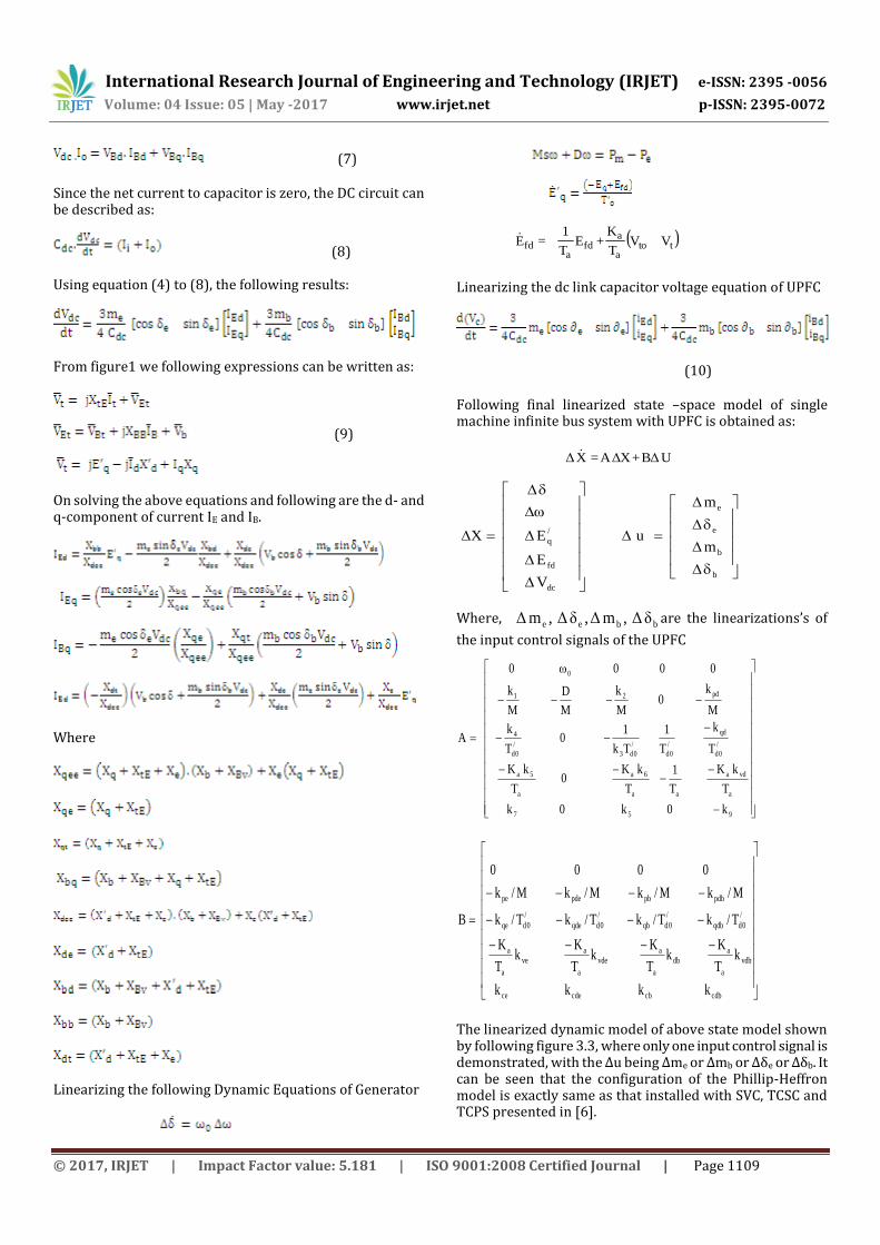
(7)
Since the net current to capacitor is zero, the DC circuit can be described as:
(8) Using equation (4) to (8), the following results:
From figure1 we following expressions can be written as:
(9)
On solving the above equations and following are the d- and q-component of current IE and IB.
Where
Linearizing the following Dynamic Equations of Generator
( )
ttoa
afd
afd VV
T
K+E
T
1=E
Linearizing the dc link capacitor voltage equation of UPFC
(10)
Following final linearized state –space model of single machine infinite bus system with UPFC is obtained as:
UΔB+XΔA=XΔ
b
b
e
e
dc
fd
/
qm
m
u
V
E
EX
Where,bbee δΔ,mΔ,δΔ,mΔ are the linearizations’s of
the input control signals of the UPFC
957
a
vda
aa
6a
a
5a
/
0d
qd
/
0d
/
0d3
/
0d
4
pd21
0
k0k0k
T
kK
T
1
T
kK0
T
kK
T
k
T
1
Tk
10
T
k
M
k0
M
k
M
D
M
k
0000
A
cdbcbcdece
vdb
a
adb
a
avde
a
ave
a
a
/
0dqdb
/
0dqb
/
0dqde
/
0dqe
pdbpbpdepe
kkkk
kT
Kk
T
Kk
T
Kk
T
K
T/kT/kT/kT/k
M/kM/kM/kM/k
0000
B
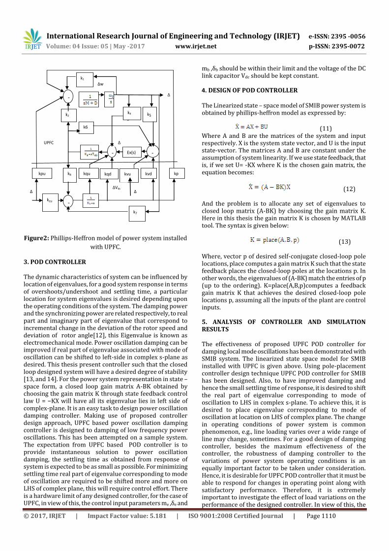
The linearized dynamic model of above state model shown by following figure 3.3, where only one input control signal is demonstrated, with the ∆u being ∆me or ∆mb or ∆δe or ∆δb. It can be seen that the configuration of the Phillip-Heffron model is exactly same as that installed with SVC, TCSC and TCPS presented in [6].
International Research Journal of Engineering and Technology (IRJET) e-ISSN: 2395 -0056
Volume: 04 Issue: 05 | May -2017 www.irjet.net p-ISSN: 2395-0072
© 2017, IRJET | Impact Factor value: 5.181 | ISO 9001:2008 Certified Journal | Page 1110
Figure2: Phillips-Heffron model of power system installed
with UPFC.
3. POD CONTROLLER The dynamic characteristics of system can be influenced by location of eigenvalues, for a good system response in terms of overshoots/undershoot and settling time, a particular location for system eigenvalues is desired depending upon the operating conditions of the system. The damping power and the synchronizing power are related respectively, to real part and imaginary part of eigenvalue that correspond to incremental change in the deviation of the rotor speed and deviation of rotor angle[12], this Eigenvalue is known as electromechanical mode. Power oscillation damping can be improved if real part of eigenvalue associated with mode of oscillation can be shifted to left-side in complex s-plane as desired. This thesis present controller such that the closed loop designed system will have a desired degree of stability [13, and 14]. For the power system representation in state – space form, a closed loop gain matrix A-BK obtained by choosing the gain matrix K through state feedback control law U = −KX will have all its eigenvalue lies in left side of complex-plane. It is an easy task to design power oscillation damping controller. Making use of proposed controller design approach, UPFC based power oscillation damping controller is designed to damping of low frequency power oscillations. This has been attempted on a sample system. The expectation from UPFC based POD controller is to provide instantaneous solution to power oscillation damping, the settling time as obtained from response of system is expected to be as small as possible. For minimizing settling time real part of eigenvalue corresponding to mode of oscillation are required to be shifted more and more on LHS of complex plane, this will require control effort. There is a hardware limit of any designed controller, for the case of UPFC, in view of this, the control input parameters me ,δe and
mb ,δb should be within their limit and the voltage of the DC link capacitor Vdc should be kept constant. 4. DESIGN OF POD CONTROLLER The Linearized state – space model of SMIB power system is obtained by phillips-heffron model as expressed by:
(11) Where A and B are the matrices of the system and input respectively. X is the system state vector, and U is the input state-vector. The matrices A and B are constant under the assumption of system linearity. If we use state feedback, that is, if we set U= -KX where K is the chosen gain matrix, the equation becomes:
(12) And the problem is to allocate any set of eigenvalues to closed loop matrix (A-BK) by choosing the gain matrix K. Here in this thesis the gain matrix K is chosen by MATLAB tool. The syntax is given below:
(13) Where, vector p of desired self-conjugate closed-loop pole locations, place computes a gain matrix K such that the state feedback places the closed-loop poles at the locations p. In other words, the eigenvalues of (A-BK) match the entries of p (up to the ordering). K=place(A,B,p)computes a feedback gain matrix K that achieves the desired closed-loop pole locations p, assuming all the inputs of the plant are control inputs. 5. ANALYSIS OF CONTROLLER AND SIMULATION RESULTS The effectiveness of proposed UPFC POD controller for damping local mode oscillations has been demonstrated with SMIB system. The linearized state space model for SMIB installed with UPFC is given above. Using pole-placement controller design technique UPFC POD controller for SMIB has been designed. Also, to have improved damping and hence the small settling time of response, it is desired to shift the real part of eigenvalue corresponding to mode of oscillation to LHS in complex s-plane. To achieve this, it is desired to place eigenvalue corresponding to mode of oscillation at location on LHS of complex plane. The change in operating conditions of power system is common phenomenon, e.g., line loading varies over a wide range of line may change, sometimes. For a good design of damping controller, besides the maximum effectiveness of the controller, the robustness of damping controller to the variations of power system operating conditions is an equally important factor to be taken under consideration. Hence, it is desirable for UPFC POD controller that it must be able to respond for changes in operating point along with satisfactory performance. Therefore, it is extremely important to investigate the effect of load variations on the performance of the designed controller. In view of this, the
∆
u
UPFC
k1
k2
k6
k4
k5
-
_
Ex(s) -
_
k8
kqu kqd kvu kvd kp
d
kcu -
-
_
-
_
kpu
k7
E’
q
∆
∆w
∆Vdc ∆
u
∆
Ef
d
International Research Journal of Engineering and Technology (IRJET) e-ISSN: 2395 -0056
Volume: 04 Issue: 05 | May -2017 www.irjet.net p-ISSN: 2395-0072
© 2017, IRJET | Impact Factor value: 5.181 | ISO 9001:2008 Certified Journal | Page 1111
performance of UPFC POD controller at following operating conditions are studied (i) 20 percent decrease in line loading (ii) 20 percent increase in line loading. For performing such investigations, the eigenvalue analysis with simulation results at each loading condition has been done. The effect of variation in modulation index, and converter angle of both converters are also considered on the performance of designed proposed controller. For performing such investigation again the eigenvalue analysis with simulation results in variation in modulation index and converter angle of both converters have been done. Eigen- values analysis under weak power system and various line loadings
Table1: Eigen values with UPFC POD controller for weak SMIB system.
Eigen- values analysis under strong power system
and various line loadings.
The bolded row of this table represents the electromechanical mode eigenvalue and its damping ratio. It can be observed from the table that UPFC with proposed controller greatly improve the system stability.
Table2: Eigen values with UPFC POD controller for strong SMIB system .
Simulation results under different system
conditions and various loading conditions.
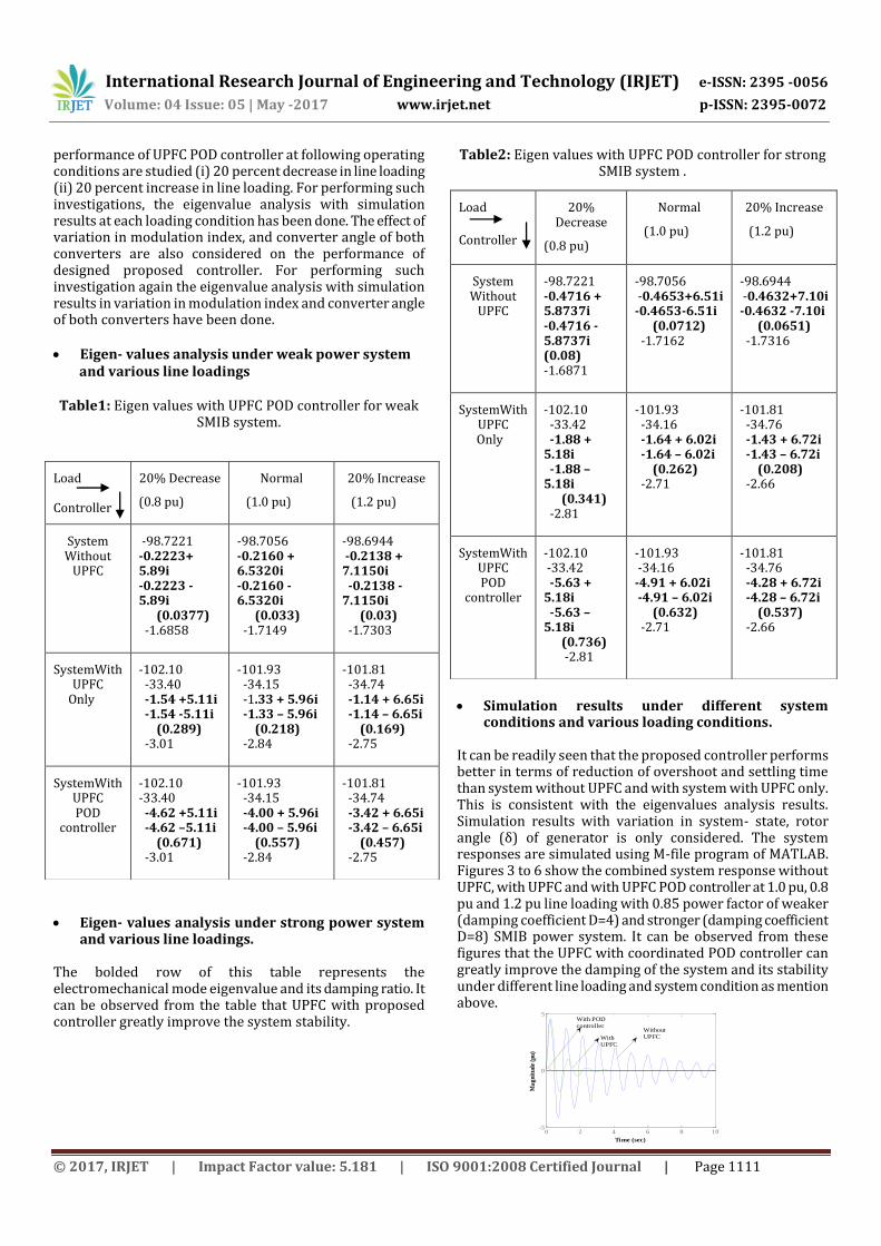
It can be readily seen that the proposed controller performs better in terms of reduction of overshoot and settling time than system without UPFC and with system with UPFC only. This is consistent with the eigenvalues analysis results. Simulation results with variation in system- state, rotor angle (δ) of generator is only considered. The system responses are simulated using M-file program of MATLAB. Figures 3 to 6 show the combined system response without UPFC, with UPFC and with UPFC POD controller at 1.0 pu, 0.8 pu and 1.2 pu line loading with 0.85 power factor of weaker (damping coefficient D=4) and stronger (damping coefficient D=8) SMIB power system. It can be observed from these figures that the UPFC with coordinated POD controller can greatly improve the damping of the system and its stability under different line loading and system condition as mention above.
Load Controller
20% Decrease
(0.8 pu)
Normal
(1.0 pu)
20% Increase
(1.2 pu)
System Without
UPFC
-98.7221 -0.2223+ 5.89i -0.2223 -5.89i (0.0377) -1.6858
-98.7056 -0.2160 + 6.5320i -0.2160 -6.5320i (0.033) -1.7149
-98.6944 -0.2138 + 7.1150i -0.2138 - 7.1150i (0.03) -1.7303
SystemWith UPFC
Only
-102.10 -33.40 -1.54 +5.11i -1.54 -5.11i (0.289) -3.01
-101.93 -34.15 -1.33 + 5.96i -1.33 – 5.96i (0.218) -2.84
-101.81 -34.74 -1.14 + 6.65i -1.14 – 6.65i (0.169) -2.75
SystemWith UPFC POD
controller
-102.10 -33.40 -4.62 +5.11i -4.62 –5.11i (0.671) -3.01
-101.93 -34.15 -4.00 + 5.96i -4.00 – 5.96i (0.557) -2.84
-101.81 -34.74 -3.42 + 6.65i -3.42 – 6.65i (0.457) -2.75
Load
Controller
20% Decrease
(0.8 pu)
Normal
(1.0 pu)
20% Increase
(1.2 pu)
System Without
UPFC
-98.7221 -0.4716 + 5.8737i -0.4716 - 5.8737i (0.08) -1.6871
-98.7056 -0.4653+6.51i -0.4653-6.51i (0.0712) -1.7162
-98.6944 -0.4632+7.10i -0.4632 -7.10i (0.0651) -1.7316
SystemWith UPFC
Only
-102.10 -33.42 -1.88 + 5.18i -1.88 – 5.18i (0.341) -2.81
-101.93 -34.16 -1.64 + 6.02i -1.64 – 6.02i (0.262) -2.71
-101.81 -34.76 -1.43 + 6.72i -1.43 – 6.72i (0.208) -2.66
SystemWith UPFC POD
controller
-102.10 -33.42 -5.63 + 5.18i -5.63 – 5.18i (0.736) -2.81
-101.93 -34.16 -4.91 + 6.02i -4.91 – 6.02i (0.632) -2.71
-101.81 -34.76 -4.28 + 6.72i -4.28 – 6.72i (0.537) -2.66
0 2 4 6 8 10-5
0
5
Time (sec)
Ma
gn
itu
de
(pu
)
WithoutUPFCWith
UPFC
With PODcontroller
International Research Journal of Engineering and Technology (IRJET) e-ISSN: 2395 -0056
Volume: 04 Issue: 05 | May -2017 www.irjet.net p-ISSN: 2395-0072
© 2017, IRJET | Impact Factor value: 5.181 | ISO 9001:2008 Certified Journal | Page 1112
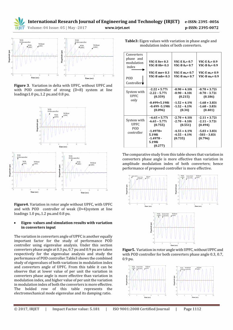
Figure 3. Variation in delta with UPFC, without UPFC and with POD controller of strong (D=8) system at line loadings1.0 pu,.1.2 pu.and 0.8 pu.
Figure4. Variation in rotor angle without UPFC, with UPFC and with POD controller of weak (D=4)system at line loadings 1.0 pu,.1.2 pu.and 0.8 pu. Eigen- values and simulation results with variation
in converters input
The variation in converters angle of UPFC is another equally important factor for the study of performance POD controller using eigenvalue analysis. Under this section converters phase angle at 0.3 pu, 0.7 pu and 0.9 pu are taken respectively for the eigenvalue analysis and study the performance of POD controller.Table3 shows the combined study of eigenvalues of both variations in modulation index and converters angle of UPFC. From this table it can be observe that at lower value of per unit the variation in converters phase angle is more effective than variation in modulation index, and higher value of per unit the variation in modulation index of both the converters is more effective. The bolded row of this table represents the electromechanical mode eigenvalue and its damping ratio.
Table3: Eigen values with variation in phase angle and modulation index of both converters.
Converters phase and modulation index
POD
Controller
VSC-E δe= 0.3 VSC-B δb= 0.3 VSC-E me= 0.3 VSC-B mb= 0.3
VSC-E δe= 0.7 VSC-B δb= 0.7 VSC-E me= 0.7 VSC-B mb= 0.7
VSC-E δe= 0.9 VSC-B δb= 0.9 VSC-E me= 0.9 VSC-B mb= 0.9
System with UPFC only
-2.22 + 5.77i -2.22 – 5.77i
(0.359)
-0.499+5.198i -0.499 -5.198i
(0.096)
-0.90 + 4.10i -0.90 – 4.10i
(0.215)
-1.52 + 4.19i -1.52 – 4.19i (0.34)
-0.70 + 3.72i -0.70 – 3.72i
(0.186)
-1.68 + 3.83i -1.68 – 3.83i
(0.401)
System with UPFC POD
controller
--6.65 + 5.77i -6.65 – 5.77i
(0.755)
-1.4978+ 5.198i -1.4978 - 5.198i
(0.277)
-2.70 + 4.10i -2.70 – 4.10i (0.551)
-4.55 + 4.19i -4.55 – 4.19i (0.735)
-2.11 + 3.72i -2.11 – 3.72i (0.494)
-5.03 + 3.83i -503 – 3.83i (0.796)
0 2 4 6 8 10-6
-4
-2
0
2
4
6
Time (sec)
Ma
gn
itu
de (
pu
)
WithPODcontroller
WithUPFC
WithoutUPFC
0 2 4 6 8 10-4
-3
-2
-1
0
1
2
3
4
Time (sec)
Ma
gn
itu
de (
pu
)
WithPODcontroller
WithUPFC
WithoutUPFC
0 2 4 6 8 10-4
-3
-2
-1
0
1
2
3
4
5
Time (sec)
Ma
gn
itu
de (
pu
)
WithPODcontroller
WithoutUPFCWith
UPFC
0 2 4 6 8 10-4
-3
-2
-1
0
1
2
3
4
5
Time (sec)
Ma
gn
itu
de (
pu
)
WithUPFC
WithPODcontroller
WithoutUPFC
0 2 4 6 8 10-4
-3
-2
-1
0
1
2
3
4
5
Time (sec)
Ma
gn
itu
de (
pu
)
WithPODcontroller
WithoutUPFC
WithUPFC
The comparative study from this table shows that variation in converters phase angle is more effective than variation in amplitude modulation index of both converters; hence performance of proposed controller is more effective.
0 2 4 6 8 10-8
-6
-4
-2
0
2
4
6
8
Time (sec)
Ma
gn
itu
de (
pu
)
Without
UPFCWith POD
Controller
With UPFC
0 2 4 6 8 10-8
-6
-4
-2
0
2
4
6
8
Time (sec)
Ma
gn
itu
de (
pu
)WithoutUPFC
With POD Controller
With UPFC
0 2 4 6 8 10-8
-6
-4
-2
0
2
4
6
8
Time (sec)
Ma
gn
itu
de (
pu
)
WithoutUPFC
With POD Controller
With UPFC
Figur5. Variation in rotor angle with UPFC, without UPFC and with POD controller for both converters phase angle 0.3, 0.7, 0.9 pu.
0 2 4 6 8 10-8
-6
-4
-2
0
2
4
6
8
Time (sec)
Ma
gn
itu
de (
pu
)
WithoutUPFC
With POD Controller
With UPFC
0 2 4 6 8 10-8
-6
-4
-2
0
2
4
6
8
Time (sec)
Ma
gn
itu
de (
pu
)
WithoutUPFC
WithPODcontroller
WithUPFC
International Research Journal of Engineering and Technology (IRJET) e-ISSN: 2395 -0056
Volume: 04 Issue: 05 | May -2017 www.irjet.net p-ISSN: 2395-0072
© 2017, IRJET | Impact Factor value: 5.181 | ISO 9001:2008 Certified Journal | Page 1113
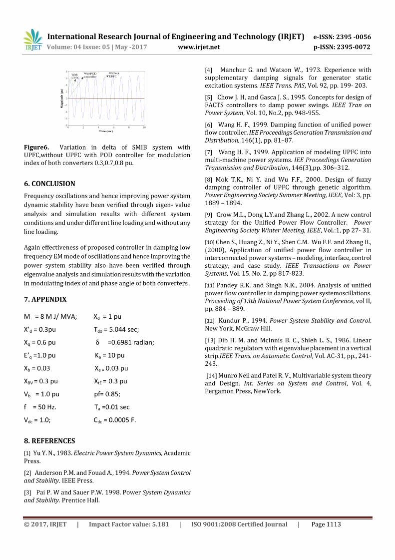
Figure6. Variation in delta of SMIB system with UPFC,without UPFC with POD controller for modulation index of both converters 0.3,0.7,0.8 pu.
6. CONCLUSION
Frequency oscillations and hence improving power system
dynamic stability have been verified through eigen- value
analysis and simulation results with different system
conditions and under different line loading and without any
line loading.
Again effectiveness of proposed controller in damping low
frequency EM mode of oscillations and hence improving the
power system stability also have been verified through
eigenvalue analysis and simulation results with the variation
in modulating index of and phase angle of both converters .
7. APPENDIX M = 8 M J/ MVA; Xd = 1 pu
X’d = 0.3pu Td0 = 5.044 sec;
Xq = 0.6 pu δ =0.6981 radian;
E’q =1.0 pu Ka = 10 pu
Xb = 0.03 Xe = 0.03 pu
XBV = 0.3 pu XtE = 0.3 pu
Vb = 1.0 pu pf= 0.85;
f = 50 Hz. Ta =0.01 sec
Vdc = 1.0; Cdc = 0.0005 F.
8. REFERENCES
[1] Yu Y. N., 1983. Electric Power System Dynamics, Academic Press.
[2] Anderson P.M. and Fouad A., 1994. Power System Control and Stability. IEEE Press.
[3] Pai P. W and Sauer P.W. 1998. Power System Dynamics and Stability. Prentice Hall.
[4] Manchur G. and Watson W., 1973. Experience with supplementary damping signals for generator static excitation systems. IEEE Trans. PAS, Vol. 92, pp. 199- 203.
[5] Chow J. H, and Gasca J. S., 1995. Concepts for design of FACTS controllers to damp power swings. IEEE Tran on Power System, Vol. 10, No.2, pp. 948-955.
[6] Wang H. F., 1999. Damping function of unified power flow controller. IEE Proceedings Generation Transmission and Distribution, 146(1), pp. 81–87.
[7] Wang H. F., 1999. Application of modeling UPFC into multi-machine power systems. IEE Proceedings Generation Transmission and Distribution, 146(3),pp. 306–312.
[8] Mok T.K., Ni Y. and Wu F.F., 2000. Design of fuzzy damping controller of UPFC through genetic algorithm. Power Engineering Society Summer Meeting, IEEE, Vol: 3, pp. 1889 – 1894.
[9] Crow M.L., Dong L.Y.and Zhang L., 2002. A new control strategy for the Unified Power Flow Controller. Power Engineering Society Winter Meeting, IEEE, Vol.:1, pp 27- 31.
[10] Chen S., Huang Z., Ni Y., Shen C.M. Wu F.F. and Zhang B., (2000), Application of unified power flow controller in interconnected power systems – modeling, interface, control strategy, and case study. IEEE Transactions on Power Systems, Vol. 15, No. 2, pp 817-823.
[11] Pandey R.K. and Singh N.K., 2004. Analysis of unified power flow controller in damping power systemoscillations. Proceeding of 13th National Power System Conference, vol II, pp. 884 – 889.
[12] Kundur P., 1994. Power System Stability and Control. New York, McGraw Hill.
[13] Dib H. M. and McInnis B. C., Shieh L. S., 1986. Linear quadratic regulators with eigenvalue placement in a vertical strip.IEEE Trans. on Automatic Control, Vol. AC-31, pp., 241-243.
[14] Munro Neil and Patel R. V., Multivariable system theory and Design. Int. Series on System and Control, Vol. 4, Pergamon Press, NewYork.
0 2 4 6 8 10-8
-6
-4
-2
0
2
4
6
8
Time (sec)
Ma
gn
itu
de
(pu
)
WithoutUPFC
WithPODcontroller
WithUPFC