Embed Size (px)
Citation preview
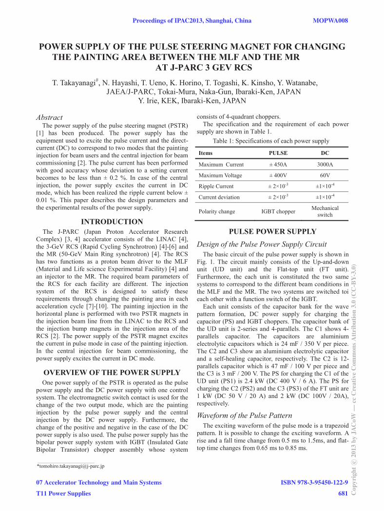
POWER SUPPLY OF THE PULSE STEERING MAGNET FOR CHANGING THE PAINTING AREA BETWEEN THE MLF AND THE MR
AT J-PARC 3 GEV RCS T. Takayanagi#, N. Hayashi, T. Ueno, K. Horino, T. Togashi, K. Kinsho, Y. Watanabe,
JAEA/J-PARC, Tokai-Mura, Naka-Gun, Ibaraki-Ken, JAPAN Y. Irie, KEK, Ibaraki-Ken, JAPAN
Abstract The power supply of the pulse steering magnet (PSTR)
[1] has been produced. The power supply has the equipment used to excite the pulse current and the direct-current (DC) to correspond to two modes that the painting injection for beam users and the central injection for beam commissioning [2]. The pulse current has been performed with good accuracy whose deviation to a setting current becomes to be less than ± 0.2 %. In case of the central injection, the power supply excites the current in DC mode, which has been realized the ripple current below ± 0.01 %. This paper describes the design parameters and the experimental results of the power supply.
INTRODUCTION The J-PARC (Japan Proton Accelerator Research
Complex) [3, 4] accelerator consists of the LINAC [4], the 3-GeV RCS (Rapid Cycling Synchrotron) [4]-[6] and the MR (50-GeV Main Ring synchrotron) [4]. The RCS has two functions as a proton beam driver to the MLF (Material and Life science Experimental Facility) [4] and an injector to the MR. The required beam parameters of the RCS for each facility are different. The injection system of the RCS is designed to satisfy these requirements through changing the painting area in each acceleration cycle [7]-[10]. The painting injection in the horizontal plane is performed with two PSTR magnets in the injection beam line from the LINAC to the RCS and the injection bump magnets in the injection area of the RCS [2]. The power supply of the PSTR magnet excites the current in pulse mode in case of the painting injection. In the central injection for beam commissioning, the power supply excites the current in DC mode.
OVERVIEW OF THE POWER SUPPLY One power supply of the PSTR is operated as the pulse
power supply and the DC power supply with one control system. The electromagnetic switch contact is used for the change of the two output mode, which are the painting injection by the pulse power supply and the central injection by the DC power supply. Furthermore, the change of the positive and negative in the case of the DC power supply is also used. The pulse power supply has the bipolar power supply system with IGBT (Insulated Gate Bipolar Transistor) chopper assembly whose system
consists of 4-quadrant choppers. The specification and the requirement of each power
supply are shown in Table 1. Table 1: Specifications of each power supply
Items PULSE DC
Maximum Current ± 450A 3000A
Maximum Voltage ± 400V 60V
Ripple Current ± 2×10⁻³ ±1×10⁻⁴
Current deviation ± 2×10⁻³ ±1×10⁻⁴
Polarity change IGBT chopper Mechanical switch
PULSE POWER SUPPLY Design of the Pulse Power Supply Circuit
The basic circuit of the pulse power supply is shown in Fig. 1. The circuit mainly consists of the Up-and-down unit (UD unit) and the Flat-top unit (FT unit). Furthermore, the each unit is constituted the two same systems to correspond to the different beam conditions in the MLF and the MR. The two systems are switched toi each other with a function switch of the IGBT.
Each unit consists of the capacitor bank for the wave pattern formation, DC power supply for charging the capacitor (PS) and IGBT choppers. The capacitor bank of the UD unit is 2-series and 4-parallels. The C1 shows 4-parallels capacitor. The capacitors are aluminium electrolytic capacitors which is 24 mF / 350 V per piece. The C2 and C3 show an aluminium electrolytic capacitor and a self-healing capacitor, respectively. The C2 is 12-parallels capacitor which is 47 mF / 100 V per piece and the C3 is 3 mF / 200 V. The PS for charging the C1 of the UD unit (PS1) is 2.4 kW (DC 400 V / 6 A). The PS for charging the C2 (PS2) and the C3 (PS3) of the FT unit are 1 kW (DC 50 V / 20 A) and 2 kW (DC 100V / 20A), respectively.
Waveform of the Pulse Pattern The exciting waveform of the pulse mode is a trapezoid
pattern. It is possible to change the exciting waveform. A rise and a fall time change from 0.5 ms to 1.5ms, and flat-top time changes from 0.65 ms to 0.85 ms.
___________________________________________
Proceedings of IPAC2013, Shanghai, China MOPWA008
07 Accelerator Technology and Main Systems
T11 Power Supplies
ISBN 978-3-95450-122-9
681 Cop
yrig
htc ○
2013
byJA
CoW
—cc
Cre
ativ
eC
omm
onsA
ttri
butio
n3.
0(C
C-B
Y-3.
0)
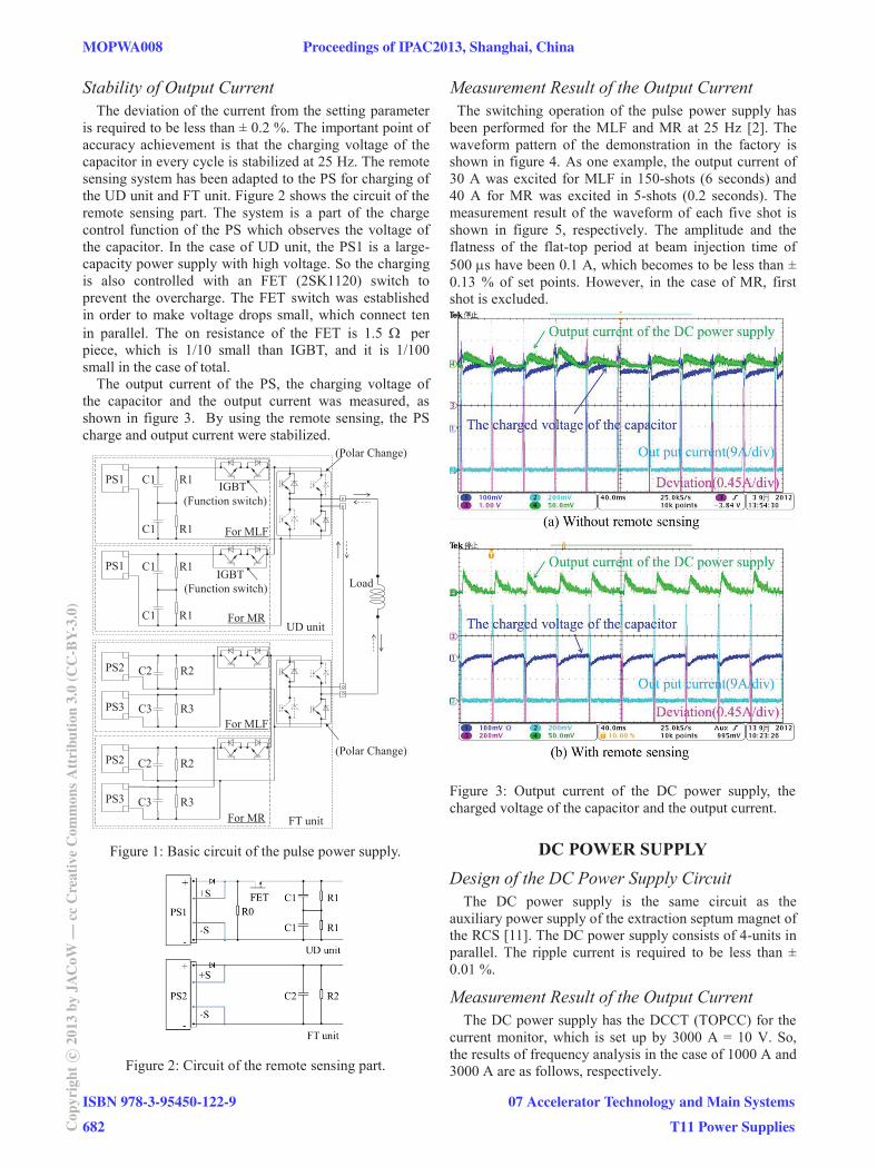
Stability of Output Current The deviation of the current from the setting parameter
is required to be less than ± 0.2 %. The important point of accuracy achievement is that the charging voltage of the capacitor in every cycle is stabilized at 25 Hz. The remote sensing system has been adapted to the PS for charging of the UD unit and FT unit. Figure 2 shows the circuit of the remote sensing part. The system is a part of the charge control function of the PS which observes the voltage of the capacitor. In the case of UD unit, the PS1 is a large-capacity power supply with high voltage. So the charging is also controlled with an FET (2SK1120) switch to prevent the overcharge. The FET switch was established in order to make voltage drops small, which connect ten in parallel. The on resistance of the FET is 1.5 per piece, which is 1/10 small than IGBT, and it is 1/100 small in the case of total.
The output current of the PS, the charging voltage of the capacitor and the output current was measured, as shown in figure 3. By using the remote sensing, the PS charge and output current were stabilized.
Figure 1: Basic circuit of the pulse power supply.
Figure 2: Circuit of the remote sensing part.
Measurement Result of the Output Current The switching operation of the pulse power supply has
been performed for the MLF and MR at 25 Hz [2]. The waveform pattern of the demonstration in the factory is shown in figure 4. As one example, the output current of 30 A was excited for MLF in 150-shots (6 seconds) and 40 A for MR was excited in 5-shots (0.2 seconds). The measurement result of the waveform of each five shot is shown in figure 5, respectively. The amplitude and the flatness of the flat-top period at beam injection time of 500 s have been 0.1 A, which becomes to be less than ± 0.13 % of set points. However, in the case of MR, first shot is excluded.
Figure 3: Output current of the DC power supply, the charged voltage of the capacitor and the output current.
DC POWER SUPPLY Design of the DC Power Supply Circuit
The DC power supply is the same circuit as the auxiliary power supply of the extraction septum magnet of the RCS [11]. The DC power supply consists of 4-units in parallel. The ripple current is required to be less than ± 0.01 %.
Measurement Result of the Output Current The DC power supply has the DCCT (TOPCC) for the
current monitor, which is set up by 3000 A = 10 V. So, the results of frequency analysis in the case of 1000 A and 3000 A are as follows, respectively.
PS1
PS1
PS2
PS3
PS2
PS3
C1 R1 IGBT(Function switch)
UD unit
FT unit
C2
C3
R2
R3
C1 R1
C1 R1
C1 R1
C2
C3
R2
R3
Load
For MLF
For MR
For MLF
For MR
(Polar Change)
(Polar Change)
IGBT(Function switch)
MOPWA008 Proceedings of IPAC2013, Shanghai, China
ISBN 978-3-95450-122-9
682Cop
yrig
htc ○
2013
byJA
CoW
—cc
Cre
ativ
eC
omm
onsA
ttri
butio
n3.
0(C
C-B
Y-3.
0)
07 Accelerator Technology and Main Systems
T11 Power Supplies
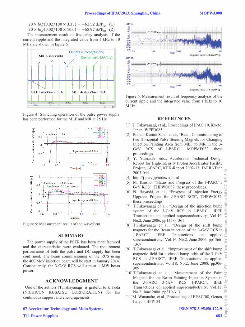
The measurement result of frequency analysis of the current ripple and the integrated value from 1 kHz to 10 MHz are shown in figure 6.
Figure 4: Switching operation of the pulse power supply has been performed for the MLF and MR at 25 Hz.
Figure 5: Measurement result of the waveform.
SUMMARY The power supply of the PSTR has been manufactured
and the characteristics were evaluated. The requirement performance of both the pulse and DC supply has been confirmed. The beam commissioning of the RCS using the 400 MeV injection beam will be start in January 2014. Consequently, the 3-GeV RCS will aim at 1 MW beam power.
ACKNOWLEDGMENT One of the authors (T.Takayanagi) is grateful to K.Toda
(NICHICON KUSATSU CORPORATION) for his continuous support and encouragements.
Figure 6: Measurement result of frequency analysis of the current ripple and the integrated value from 1 kHz to 10 M Hz.
REFERENCES [1] T. Takayanagi, et al., Proceedings of IPAC’10, Kyoto,
Japan, WEPD085 [2] Pranab Kumar Saha, et al., “Beam Commissioning of
two Horizontal Pulse Steering Magnets for Changing Injection Painting Area from MLF to MR in the 3-GeV RCS of J-PARC,” MOPME022, these proceedings.
[3] Y. Yamazaki eds., Accelerator Technical Design Report for High-Intensity Proton Accelerator Facility Project, J-PARC, KEK-Report 2002-13; JAERI-Tech 2003-044.
[4] http://j-parc.jp/index-e.html [5] M. Kinsho, “Status and Progress of the J-PARC 3
GeV RCS”, THPWO037, these proceedings. [6] N. Hayashi, et al., “Progress of Injection Energy
Upgrade Project for J-PARC RCS”, THPWO032, these proceedings.
[7] T.Takayanagi et al., “Design of the injection bump system of the 3-GeV RCS in J-PARC”, IEEE Transactions on applied superconductivity, Vol.16, No.2, June 2006, pp1358-1361
[8] T.Takayanagi et al., “Design of the shift bump magnets for the Beam injection of the 3-GeV RCS in J-PARC”, IEEE Transactions on applied superconductivity, Vol.16, No.2, June 2006, pp1366-1369
[9] T.Takayanagi et al., “Improvement of the shift bump magnetic field for a closed bump orbit of the 3-GeV RCS in J-PARC”, IEEE Transactions on applied superconductivity, Vol.18, No.2, June 2008, pp306-309
[10] T.Takayanagi et al., “Measurement of the Paint Magnets for the Beam Painting Injection System in the J-PARC 3-GeV RCS J-PARC”, IEEE Transactions on applied superconductivity, Vol.18, No.2, June 2008, pp310-313
[11]M. Watanabe, et al., Proceedings of EPAC’08, Genoa, Italy, THPP134
Proceedings of IPAC2013, Shanghai, China MOPWA008
07 Accelerator Technology and Main Systems
T11 Power Supplies
ISBN 978-3-95450-122-9
683 Cop
yrig
htc ○
2013
byJA
CoW
—cc
Cre
ativ
eC
omm
onsA
ttri
butio
n3.
0(C
C-B
Y-3.
0)