Embed Size (px)
Citation preview
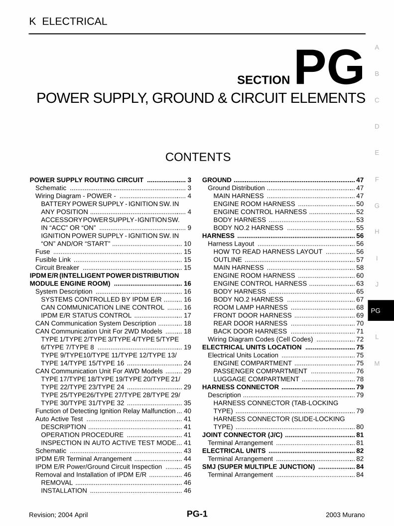
PG-1
POWER SUPPLY, GROUND & CIRCUIT ELEMENTS
K ELECTRICAL
CONTENTS
C
D
E
F
G
H
I
J
L
M
SECTION PGA
B
PG
Revision; 2004 April 2003 Murano
POWER SUPPLY, GROUND & CIRCUIT ELEMENTS
POWER SUPPLY ROUTING CIRCUIT ...................... 3Schematic ................................................................ 3Wiring Diagram - POWER - ..................................... 4
BATTERY POWER SUPPLY - IGNITION SW. IN ANY POSITION ..................................................... 4ACCESSORY POWER SUPPLY - IGNITION SW. IN “ACC” OR “ON” ................................................ 9IGNITION POWER SUPPLY - IGNITION SW. IN “ON” AND/OR “START” ....................................... 10
Fuse ....................................................................... 15Fusible Link ............................................................ 15Circuit Breaker ....................................................... 15
IPDM E/R (INTELLIGENT POWER DISTRIBUTION MODULE ENGINE ROOM) ...................................... 16
System Description ................................................ 16SYSTEMS CONTROLLED BY IPDM E/R ........... 16CAN COMMUNICATION LINE CONTROL ......... 16IPDM E/R STATUS CONTROL ........................... 17
CAN Communication System Description .............. 18CAN Communication Unit For 2WD Models .......... 18
TYPE 1/TYPE 2/TYPE 3/TYPE 4/TYPE 5/TYPE 6/TYPE 7/TYPE 8 ............................................... 19TYPE 9/TYPE10/TYPE 11/TYPE 12/TYPE 13/TYPE 14/TYPE 15/TYPE 16 ............................... 24
CAN Communication Unit For AWD Models .......... 29TYPE 17/TYPE 18/TYPE 19/TYPE 20/TYPE 21/TYPE 22/TYPE 23/TYPE 24 ............................... 29TYPE 25/TYPE26/TYPE 27/TYPE 28/TYPE 29/TYPE 30/TYPE 31/TYPE 32 ............................... 35
Function of Detecting Ignition Relay Malfunction ... 40Auto Active Test ..................................................... 41
DESCRIPTION .................................................... 41OPERATION PROCEDURE ............................... 41INSPECTION IN AUTO ACTIVE TEST MODE ... 41
Schematic .............................................................. 43IPDM E/R Terminal Arrangement ........................... 44IPDM E/R Power/Ground Circuit Inspection .......... 45Removal and Installation of IPDM E/R ................... 46
REMOVAL ........................................................... 46INSTALLATION ................................................... 46
GROUND ................................................................... 47Ground Distribution ................................................. 47
MAIN HARNESS ................................................. 47ENGINE ROOM HARNESS ................................ 50ENGINE CONTROL HARNESS .......................... 52BODY HARNESS ................................................ 53BODY NO.2 HARNESS ...................................... 55
HARNESS ................................................................. 56Harness Layout ...................................................... 56
HOW TO READ HARNESS LAYOUT ................. 56OUTLINE ............................................................. 57MAIN HARNESS ................................................. 58ENGINE ROOM HARNESS ................................ 60ENGINE CONTROL HARNESS .......................... 63BODY HARNESS ................................................ 65BODY NO.2 HARNESS ...................................... 67ROOM LAMP HARNESS .................................... 68FRONT DOOR HARNESS .................................. 69REAR DOOR HARNESS .................................... 70BACK DOOR HARNESS .................................... 71
Wiring Diagram Codes (Cell Codes) ...................... 72ELECTRICAL UNITS LOCATION ............................ 75
Electrical Units Location ......................................... 75ENGINE COMPARTMENT .................................. 75PASSENGER COMPARTMENT ......................... 76LUGGAGE COMPARTMENT .............................. 78
HARNESS CONNECTOR ......................................... 79Description .............................................................. 79
HARNESS CONNECTOR (TAB-LOCKING TYPE) .................................................................. 79HARNESS CONNECTOR (SLIDE-LOCKING TYPE) .................................................................. 80
JOINT CONNECTOR (J/C) ....................................... 81Terminal Arrangement ............................................ 81
ELECTRICAL UNITS ................................................ 82Terminal Arrangement ............................................ 82
SMJ (SUPER MULTIPLE JUNCTION) ..................... 84Terminal Arrangement ............................................ 84
PG-2Revision; 2004 April 2003 Murano
STANDARDIZED RELAY .......................................... 85Description .............................................................. 85
NORMAL OPEN, NORMAL CLOSED AND MIXED TYPE RELAYS ........................................ 85TYPE OF STANDARDIZED RELAYS .................. 85
FUSE BLOCK - JUNCTION BOX (J/B) ....................87Terminal Arrangement .............................................87
FUSE, FUSIBLE LINK AND RELAY BOX ................88Terminal Arrangement .............................................88
POWER SUPPLY ROUTING CIRCUIT
PG-3
C
D
E
F
G
H
I
J
L
M
A
B
PG
Revision; 2004 April 2003 Murano
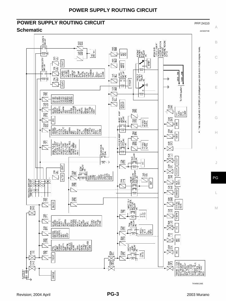
POWER SUPPLY ROUTING CIRCUIT PFP:24110
Schematic AKS007HE
TKWB0136E
PG-4
POWER SUPPLY ROUTING CIRCUIT
Revision; 2004 April 2003 Murano
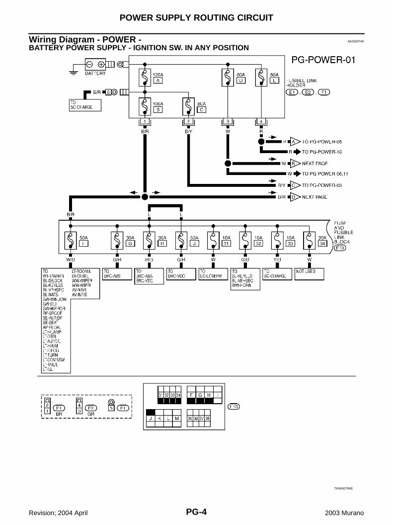
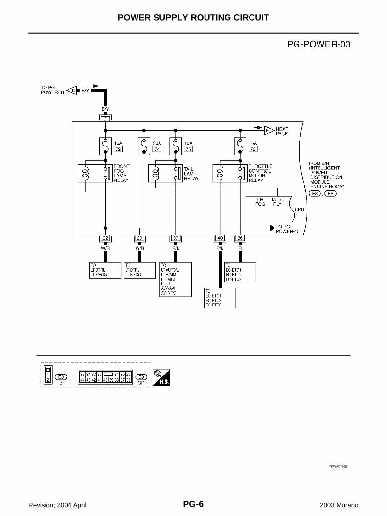
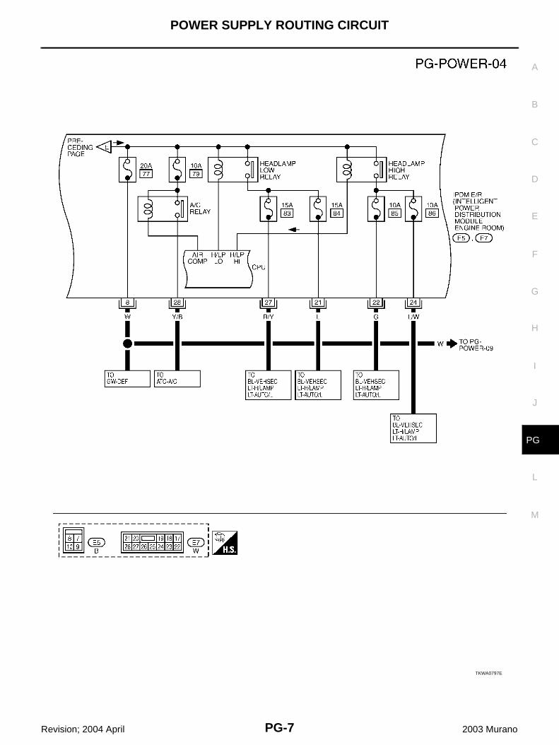
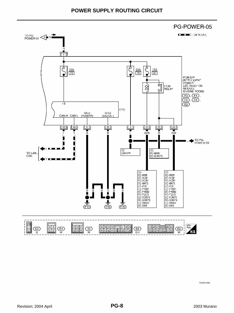
Wiring Diagram - POWER - AKS007HF
BATTERY POWER SUPPLY - IGNITION SW. IN ANY POSITION
TKWA0794E
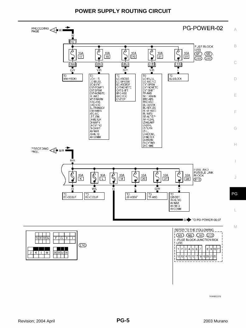
POWER SUPPLY ROUTING CIRCUIT
PG-5
C
D
E
F
G
H
I
J
L
M
A
B
PG
Revision; 2004 April 2003 Murano
TKWB0137E
PG-6
POWER SUPPLY ROUTING CIRCUIT
Revision; 2004 April 2003 Murano
TKWA0796E
POWER SUPPLY ROUTING CIRCUIT
PG-7
C
D
E
F
G
H
I
J
L
M
A
B
PG
Revision; 2004 April 2003 Murano
TKWA0797E
PG-8
POWER SUPPLY ROUTING CIRCUIT
Revision; 2004 April 2003 Murano
TKWA0798E
POWER SUPPLY ROUTING CIRCUIT
PG-9
C
D
E
F
G
H
I
J
L
M
A
B
PG
Revision; 2004 April 2003 Murano
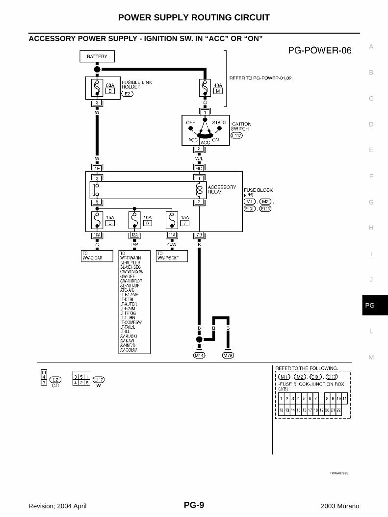
ACCESSORY POWER SUPPLY - IGNITION SW. IN “ACC” OR “ON”
TKWA0799E
PG-10
POWER SUPPLY ROUTING CIRCUIT
Revision; 2004 April 2003 Murano
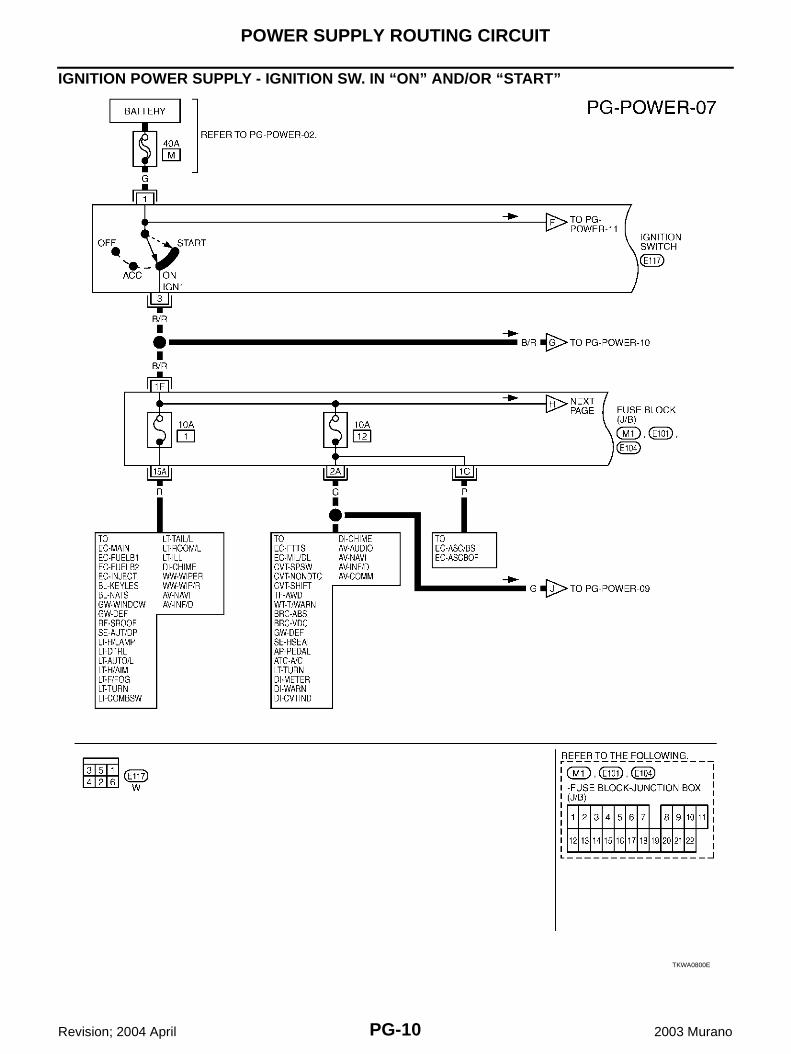
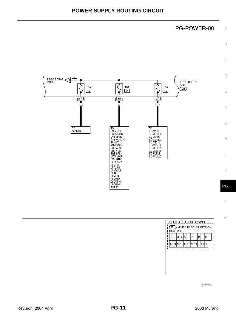
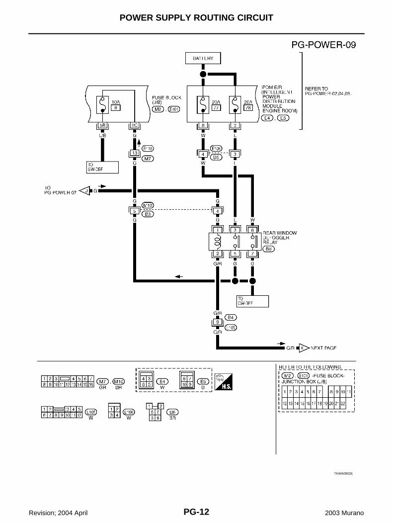
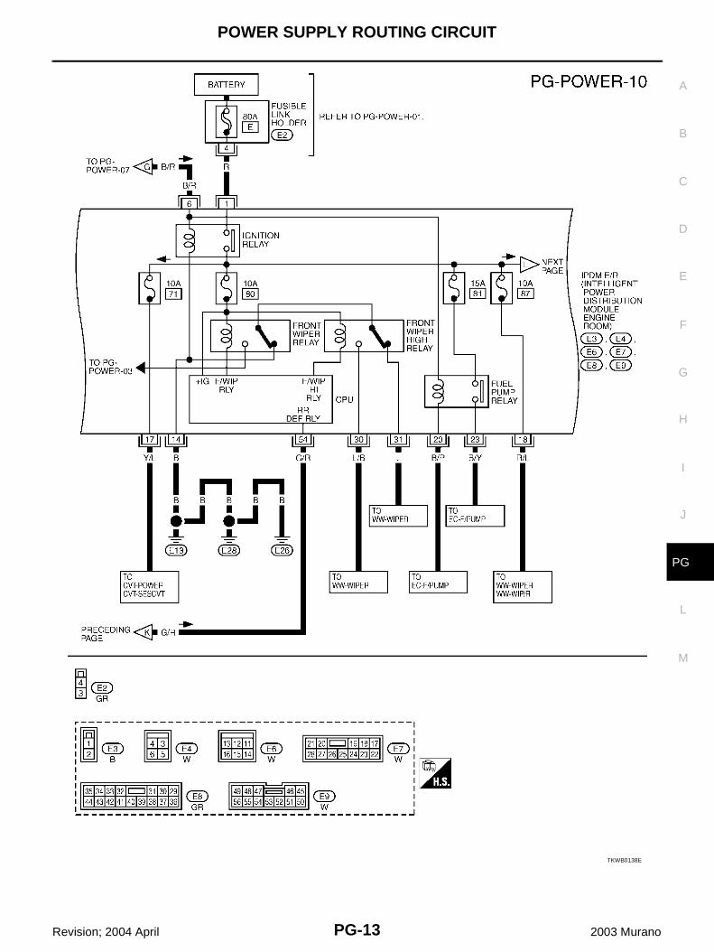
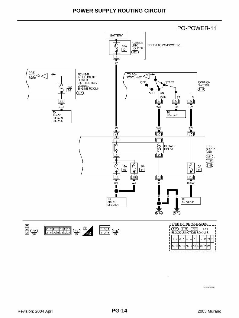
IGNITION POWER SUPPLY - IGNITION SW. IN “ON” AND/OR “START”
TKWA0800E
POWER SUPPLY ROUTING CIRCUIT
PG-11
C
D
E
F
G
H
I
J
L
M
A
B
PG
Revision; 2004 April 2003 Murano
TKWA0801E
PG-12
POWER SUPPLY ROUTING CIRCUIT
Revision; 2004 April 2003 Murano
TKWA0802E
POWER SUPPLY ROUTING CIRCUIT
PG-13
C
D
E
F
G
H
I
J
L
M
A
B
PG
Revision; 2004 April 2003 Murano
TKWB0138E
PG-14
POWER SUPPLY ROUTING CIRCUIT
Revision; 2004 April 2003 Murano
TKWA0804E
POWER SUPPLY ROUTING CIRCUIT
PG-15
C
D
E
F
G
H
I
J
L
M
A
B
PG
Revision; 2004 April 2003 Murano
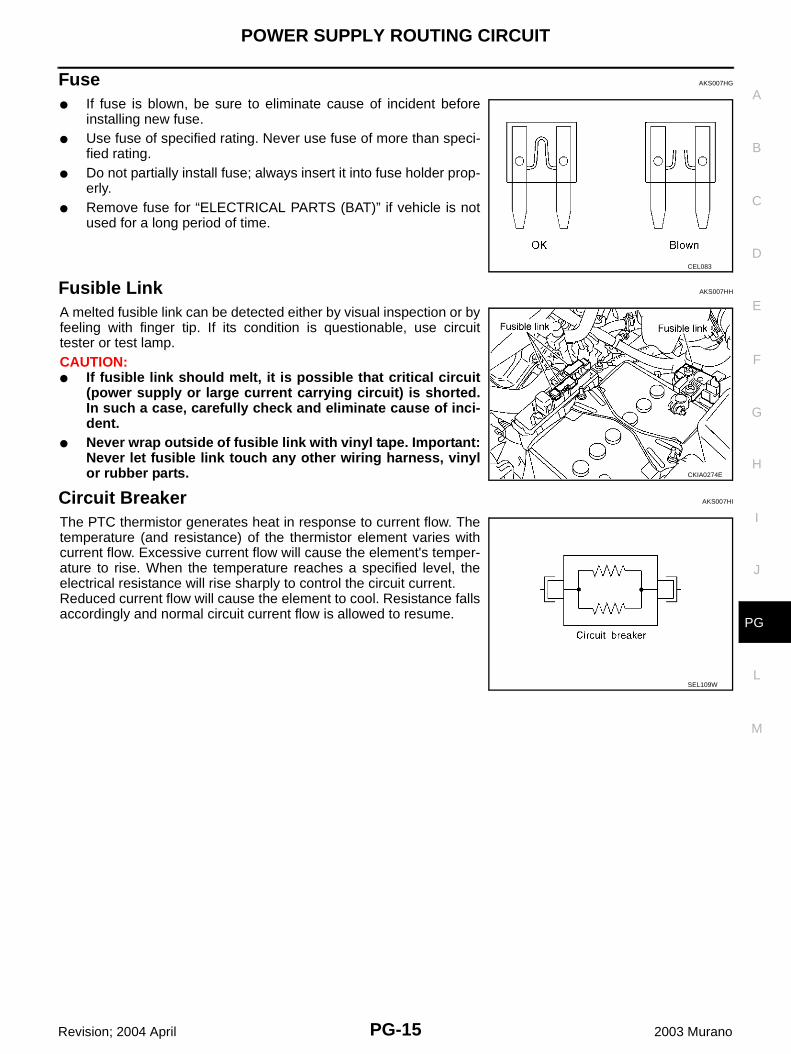
Fuse AKS007HG
● If fuse is blown, be sure to eliminate cause of incident beforeinstalling new fuse.
● Use fuse of specified rating. Never use fuse of more than speci-fied rating.
● Do not partially install fuse; always insert it into fuse holder prop-erly.
● Remove fuse for “ELECTRICAL PARTS (BAT)” if vehicle is notused for a long period of time.
Fusible Link AKS007HH
A melted fusible link can be detected either by visual inspection or byfeeling with finger tip. If its condition is questionable, use circuittester or test lamp.CAUTION:● If fusible link should melt, it is possible that critical circuit
(power supply or large current carrying circuit) is shorted.In such a case, carefully check and eliminate cause of inci-dent.
● Never wrap outside of fusible link with vinyl tape. Important:Never let fusible link touch any other wiring harness, vinylor rubber parts.
Circuit Breaker AKS007HI
The PTC thermistor generates heat in response to current flow. Thetemperature (and resistance) of the thermistor element varies withcurrent flow. Excessive current flow will cause the element's temper-ature to rise. When the temperature reaches a specified level, theelectrical resistance will rise sharply to control the circuit current.Reduced current flow will cause the element to cool. Resistance fallsaccordingly and normal circuit current flow is allowed to resume.
CEL083
CKIA0274E
SEL109W
PG-16
IPDM E/R (INTELLIGENT POWER DISTRIBUTION MODULE ENGINE ROOM)
Revision; 2004 April 2003 Murano
IPDM E/R (INTELLIGENT POWER DISTRIBUTION MODULE ENGINE ROOM)PFP:284B7
System Description AKS004CK
● IPDM E/R (Intelligent Power Distribution Module Engine Room) integrates the relay box and fuse blockwhich were originally placed in engine compartment. It controls integrated relay via IPDM E/R control cir-cuit.
● IPDM E/R-integrated control circuit performs ON-OFF operation of relay, CAN communication control, oilpressure switch signal reception, etc.
● It controls operation of each electrical part via BCM and CAN communication lines.CAUTION:None of the IPDM E/R-integrated relays can be removed.
SYSTEMS CONTROLLED BY IPDM E/R1. Lamp control
Using CAN communication line, it receives signal from BCM and controls the following lamps:● Head lamps (Hi, Lo)● Parking lamps● Tail lamps● Front fog lamps
2. Wiper controlUsing CAN communication line, it receives signals from BCM and controls the front wipers.
3. Rear window defogger relay controlUsing CAN communication line, it receives signals from BCM and controls the rear window defoggerrelay.
4. A/C compressor controlUsing CAN communication line, it receives signals from ECM and controls the A/C compressor (magnetclutch).
5. Cooling fan controlUsing CAN communication line, it receives signals from ECM and controls cooling fan.
6. Horn controlUsing CAN communication line, it receives signals from BCM and controls horn relay.
CAN COMMUNICATION LINE CONTROLWith CAN communication, by connecting each control unit using two communication lines (CAN L-line, CANH-line), it is possible to transmit maximum amount of information with minimum wiring. Each control unit cantransmit and receive data, and reads necessary information only.1. Fail-safe control
● When CAN communication with other control units is impossible, IPDM E/R performs fail-safe control.After CAN communication recovers normally, it also returns to normal control.
● Operation of control parts by IPDM E/R during fail-safe mode is as follows:
Controlled system Fail-safe mode
Headlamp● With the ignition switch ON, the headlamp (low) is ON.
● With the ignition switch OFF, the headlamp (low) is OFF.
Tail and parking lamps Tail and parking lamps OFF.
Cooling fan● With the ignition switch ON, the cooling fan HI operates.
● With the ignition switch OFF, the cooling fan stops.
Front wiperUntil the ignition switch is turned off, the front wiper LO and HI remains in the same status it was in just before fail−safe control was initiated.
Rear window defogger Rear window defogger relay OFF
A/C compressor A/C compressor OFF
Front fog lamps Front fog lamp relay OFF
IPDM E/R (INTELLIGENT POWER DISTRIBUTION MODULE ENGINE ROOM)
PG-17
C
D
E
F
G
H
I
J
L
M
A
B
PG
Revision; 2004 April 2003 Murano
IPDM E/R STATUS CONTROLIn order to save power, IPDM E/R switches status by itself based on each operating condition.1. CAN communication status
● CAN communication is normally performed with other control units.● Individual unit control by IPDM E/R is normally performed.● When sleep request signal is received from BCM, mode is switched to sleep waiting status.
2. Sleep waiting status● Process to stop CAN communication is activated.● All systems controlled by IPDM E/R are stopped. When 3 seconds have elapsed after CAN communi-
cation with other control units is stopped, mode switches to sleep status.3. Sleep status
● IPDM E/R operates in low current-consumption mode.● CAN communication is stopped.● When a change in CAN communication signal is detected, mode switches to CAN communication sta-
tus.● When a change hood switch signal is detected, mode switches to CAN communication status.
PG-18
IPDM E/R (INTELLIGENT POWER DISTRIBUTION MODULE ENGINE ROOM)
Revision; 2004 April 2003 Murano
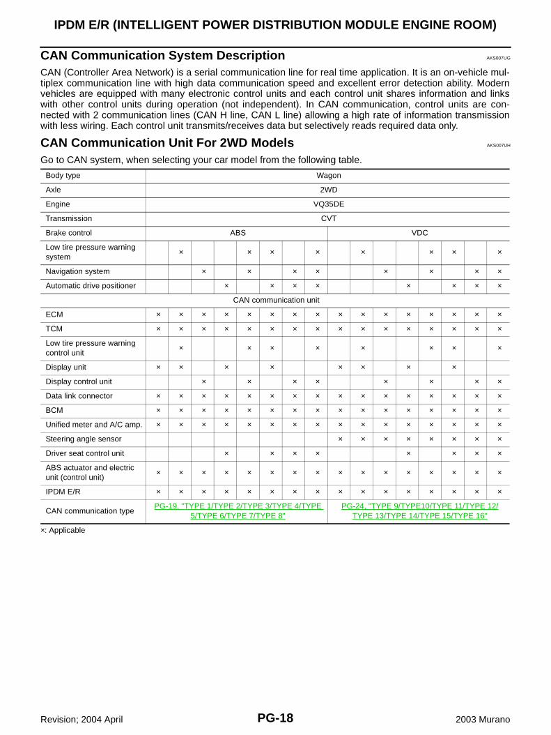
CAN Communication System Description AKS007UG
CAN (Controller Area Network) is a serial communication line for real time application. It is an on-vehicle mul-tiplex communication line with high data communication speed and excellent error detection ability. Modernvehicles are equipped with many electronic control units and each control unit shares information and linkswith other control units during operation (not independent). In CAN communication, control units are con-nected with 2 communication lines (CAN H line, CAN L line) allowing a high rate of information transmissionwith less wiring. Each control unit transmits/receives data but selectively reads required data only.
CAN Communication Unit For 2WD Models AKS007UH
Go to CAN system, when selecting your car model from the following table.
×: Applicable
Body type Wagon
Axle 2WD
Engine VQ35DE
Transmission CVT
Brake control ABS VDC
Low tire pressure warning system
× × × × × × × ×
Navigation system × × × × × × × ×
Automatic drive positioner × × × × × × × ×
CAN communication unit
ECM × × × × × × × × × × × × × × × ×
TCM × × × × × × × × × × × × × × × ×
Low tire pressure warning control unit
× × × × × × × ×
Display unit × × × × × × × ×
Display control unit × × × × × × × ×
Data link connector × × × × × × × × × × × × × × × ×
BCM × × × × × × × × × × × × × × × ×
Unified meter and A/C amp. × × × × × × × × × × × × × × × ×
Steering angle sensor × × × × × × × ×
Driver seat control unit × × × × × × × ×
ABS actuator and electric unit (control unit)
× × × × × × × × × × × × × × × ×
IPDM E/R × × × × × × × × × × × × × × × ×
CAN communication typePG-19, "TYPE 1/TYPE 2/TYPE 3/TYPE 4/TYPE
5/TYPE 6/TYPE 7/TYPE 8"PG-24, "TYPE 9/TYPE10/TYPE 11/TYPE 12/
TYPE 13/TYPE 14/TYPE 15/TYPE 16"
IPDM E/R (INTELLIGENT POWER DISTRIBUTION MODULE ENGINE ROOM)
PG-19
C
D
E
F
G
H
I
J
L
M
A
B
PG
Revision; 2004 April 2003 Murano
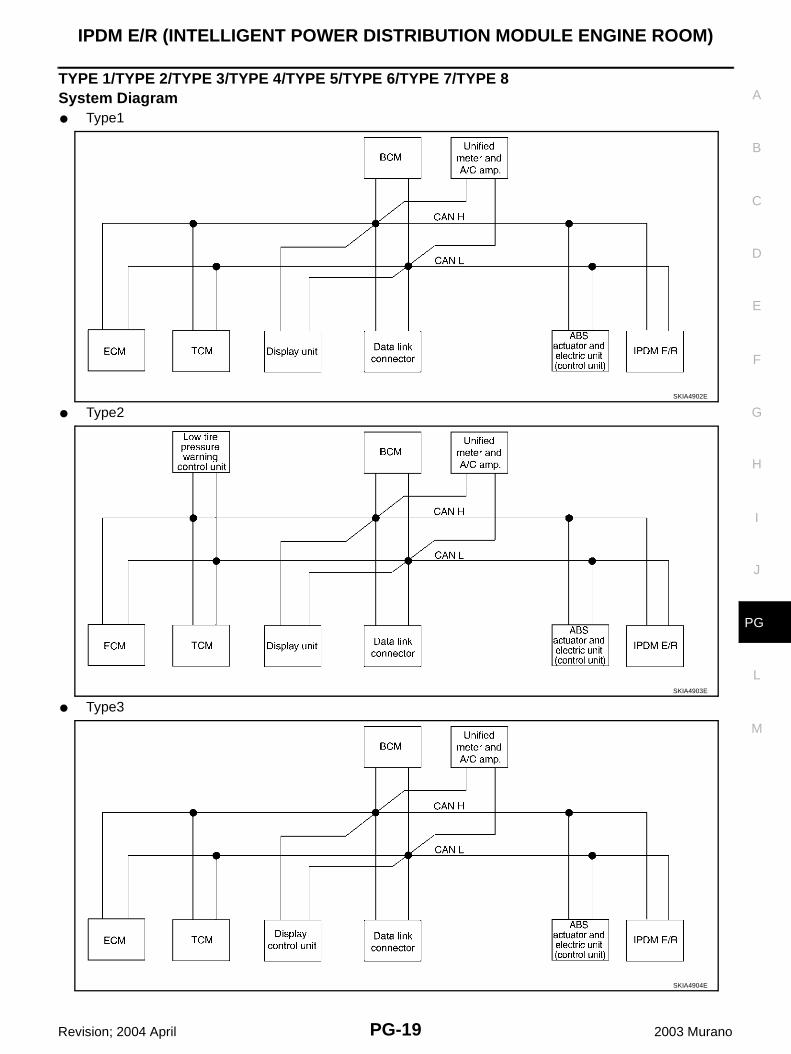
TYPE 1/TYPE 2/TYPE 3/TYPE 4/TYPE 5/TYPE 6/TYPE 7/TYPE 8System Diagram● Type1
● Type2
● Type3
SKIA4902E
SKIA4903E
SKIA4904E
PG-20
IPDM E/R (INTELLIGENT POWER DISTRIBUTION MODULE ENGINE ROOM)
Revision; 2004 April 2003 Murano
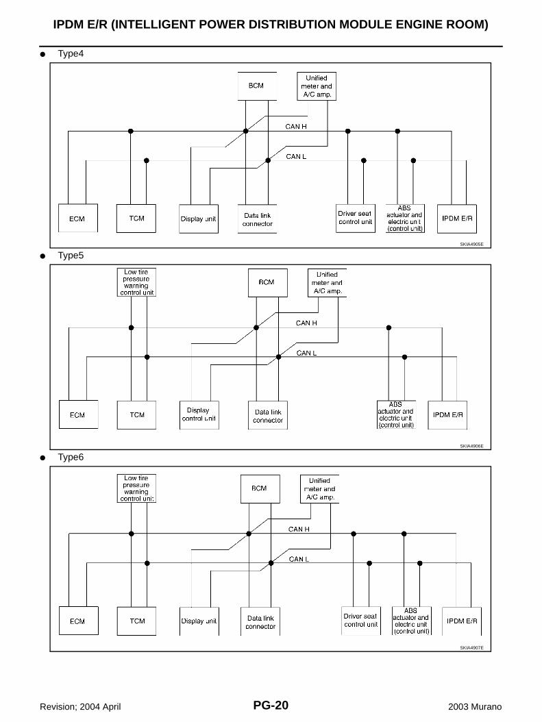
● Type4
● Type5
● Type6
SKIA4905E
SKIA4906E
SKIA4907E
IPDM E/R (INTELLIGENT POWER DISTRIBUTION MODULE ENGINE ROOM)
PG-21
C
D
E
F
G
H
I
J
L
M
A
B
PG
Revision; 2004 April 2003 Murano
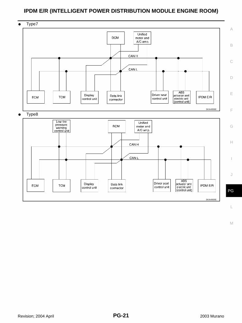
● Type7
● Type8SKIA4908E
SKIA4909E
PG-22
IPDM E/R (INTELLIGENT POWER DISTRIBUTION MODULE ENGINE ROOM)
Revision; 2004 April 2003 Murano
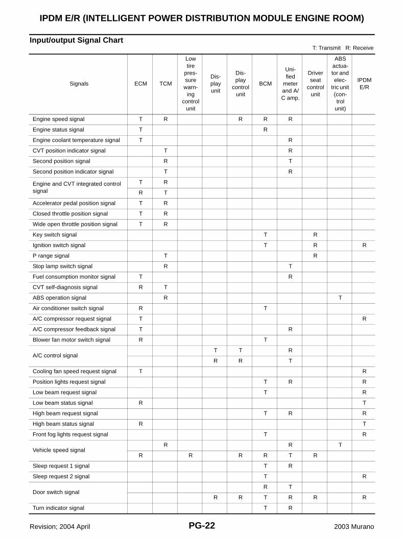
Input/output Signal ChartT: Transmit R: Receive
Signals ECM TCM
Low tire
pres-sure
warn-ing
control unit
Dis-play unit
Dis-play
control unit
BCM
Uni-fied
meter and A/C amp.
Driver seat
control unit
ABS actua-tor and elec-
tric unit (con-trol
unit)
IPDM E/R
Engine speed signal T R R R R
Engine status signal T R
Engine coolant temperature signal T R
CVT position indicator signal T R
Second position signal R T
Second position indicator signal T R
Engine and CVT integrated control signal
T R
R T
Accelerator pedal position signal T R
Closed throttle position signal T R
Wide open throttle position signal T R
Key switch signal T R
Ignition switch signal T R R
P range signal T R
Stop lamp switch signal R T
Fuel consumption monitor signal T R
CVT self-diagnosis signal R T
ABS operation signal R T
Air conditioner switch signal R T
A/C compressor request signal T R
A/C compressor feedback signal T R
Blower fan motor switch signal R T
A/C control signalT T R
R R T
Cooling fan speed request signal T R
Position lights request signal T R R
Low beam request signal T R
Low beam status signal R T
High beam request signal T R R
High beam status signal R T
Front fog lights request signal T R
Vehicle speed signalR R T
R R R R T R
Sleep request 1 signal T R
Sleep request 2 signal T R
Door switch signalR T
R R T R R R
Turn indicator signal T R
IPDM E/R (INTELLIGENT POWER DISTRIBUTION MODULE ENGINE ROOM)
PG-23
C
D
E
F
G
H
I
J
L
M
A
B
PG
Revision; 2004 April 2003 Murano
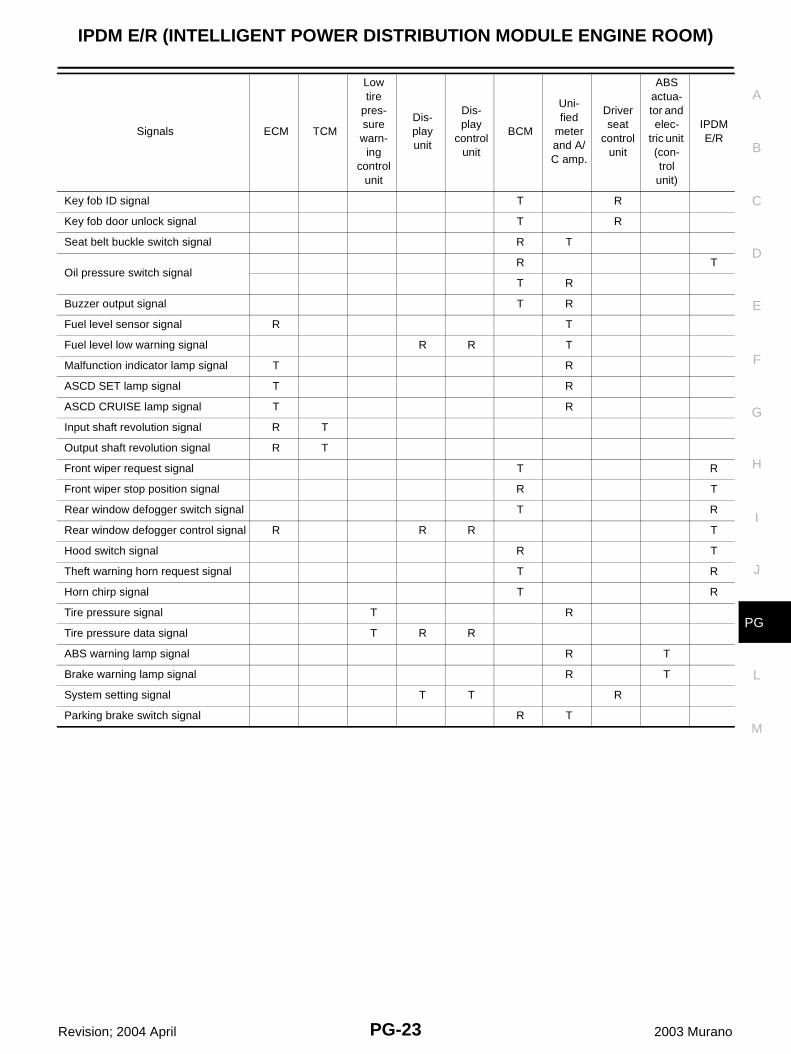
Key fob ID signal T R
Key fob door unlock signal T R
Seat belt buckle switch signal R T
Oil pressure switch signalR T
T R
Buzzer output signal T R
Fuel level sensor signal R T
Fuel level low warning signal R R T
Malfunction indicator lamp signal T R
ASCD SET lamp signal T R
ASCD CRUISE lamp signal T R
Input shaft revolution signal R T
Output shaft revolution signal R T
Front wiper request signal T R
Front wiper stop position signal R T
Rear window defogger switch signal T R
Rear window defogger control signal R R R T
Hood switch signal R T
Theft warning horn request signal T R
Horn chirp signal T R
Tire pressure signal T R
Tire pressure data signal T R R
ABS warning lamp signal R T
Brake warning lamp signal R T
System setting signal T T R
Parking brake switch signal R T
Signals ECM TCM
Low tire
pres-sure warn-
ing control
unit
Dis-play unit
Dis-play
control unit
BCM
Uni-fied
meter and A/C amp.
Driver seat
control unit
ABS actua-tor and elec-
tric unit (con-trol
unit)
IPDM E/R
PG-24
IPDM E/R (INTELLIGENT POWER DISTRIBUTION MODULE ENGINE ROOM)
Revision; 2004 April 2003 Murano
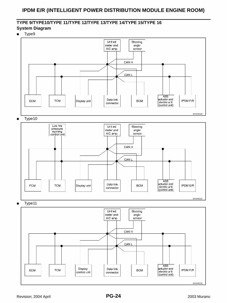
TYPE 9/TYPE10/TYPE 11/TYPE 12/TYPE 13/TYPE 14/TYPE 15/TYPE 16System Diagram● Type9
● Type10
● Type11
SKIA4910E
SKIA4911E
SKIA4912E
IPDM E/R (INTELLIGENT POWER DISTRIBUTION MODULE ENGINE ROOM)
PG-25
C
D
E
F
G
H
I
J
L
M
A
B
PG
Revision; 2004 April 2003 Murano
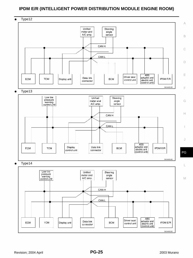
● Type12
● Type13
● Type14
SKIA4913E
SKIA4914E
SKIA4915E
PG-26
IPDM E/R (INTELLIGENT POWER DISTRIBUTION MODULE ENGINE ROOM)
Revision; 2004 April 2003 Murano
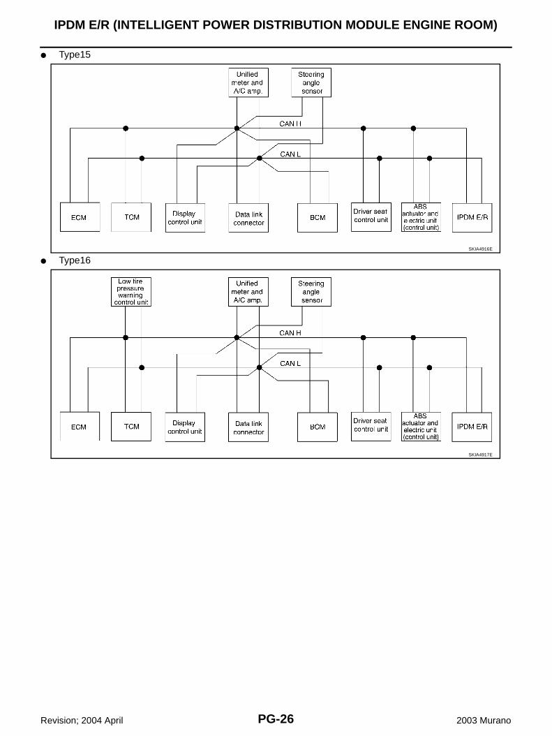
● Type15
● Type16SKIA4916E
SKIA4917E
IPDM E/R (INTELLIGENT POWER DISTRIBUTION MODULE ENGINE ROOM)
PG-27
C
D
E
F
G
H
I
J
L
M
A
B
PG
Revision; 2004 April 2003 Murano
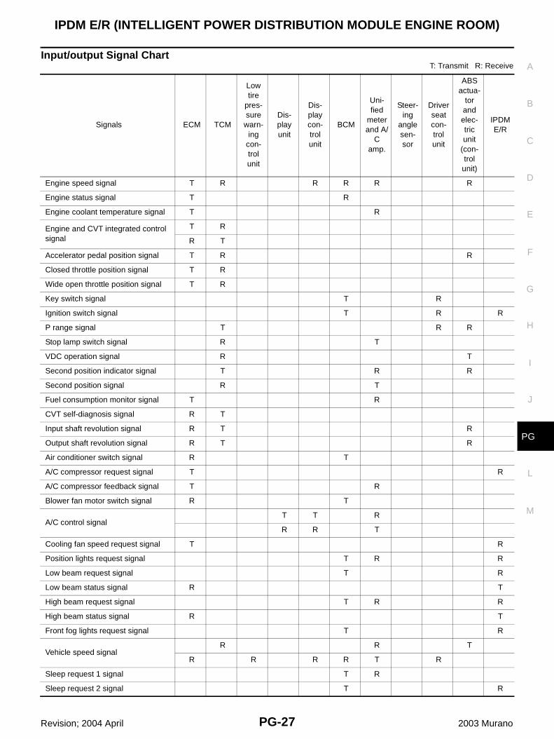
Input/output Signal ChartT: Transmit R: Receive
Signals ECM TCM
Low tire
pres-sure
warn-ing
con-trol unit
Dis-play unit
Dis-play con-trol unit
BCM
Uni-fied
meter and A/
C amp.
Steer-ing
angle sen-sor
Driver seat con-trol unit
ABS actua-
tor and elec-tric unit
(con-trol unit)
IPDM E/R
Engine speed signal T R R R R R
Engine status signal T R
Engine coolant temperature signal T R
Engine and CVT integrated control signal
T R
R T
Accelerator pedal position signal T R R
Closed throttle position signal T R
Wide open throttle position signal T R
Key switch signal T R
Ignition switch signal T R R
P range signal T R R
Stop lamp switch signal R T
VDC operation signal R T
Second position indicator signal T R R
Second position signal R T
Fuel consumption monitor signal T R
CVT self-diagnosis signal R T
Input shaft revolution signal R T R
Output shaft revolution signal R T R
Air conditioner switch signal R T
A/C compressor request signal T R
A/C compressor feedback signal T R
Blower fan motor switch signal R T
A/C control signalT T R
R R T
Cooling fan speed request signal T R
Position lights request signal T R R
Low beam request signal T R
Low beam status signal R T
High beam request signal T R R
High beam status signal R T
Front fog lights request signal T R
Vehicle speed signalR R T
R R R R T R
Sleep request 1 signal T R
Sleep request 2 signal T R
PG-28
IPDM E/R (INTELLIGENT POWER DISTRIBUTION MODULE ENGINE ROOM)
Revision; 2004 April 2003 Murano
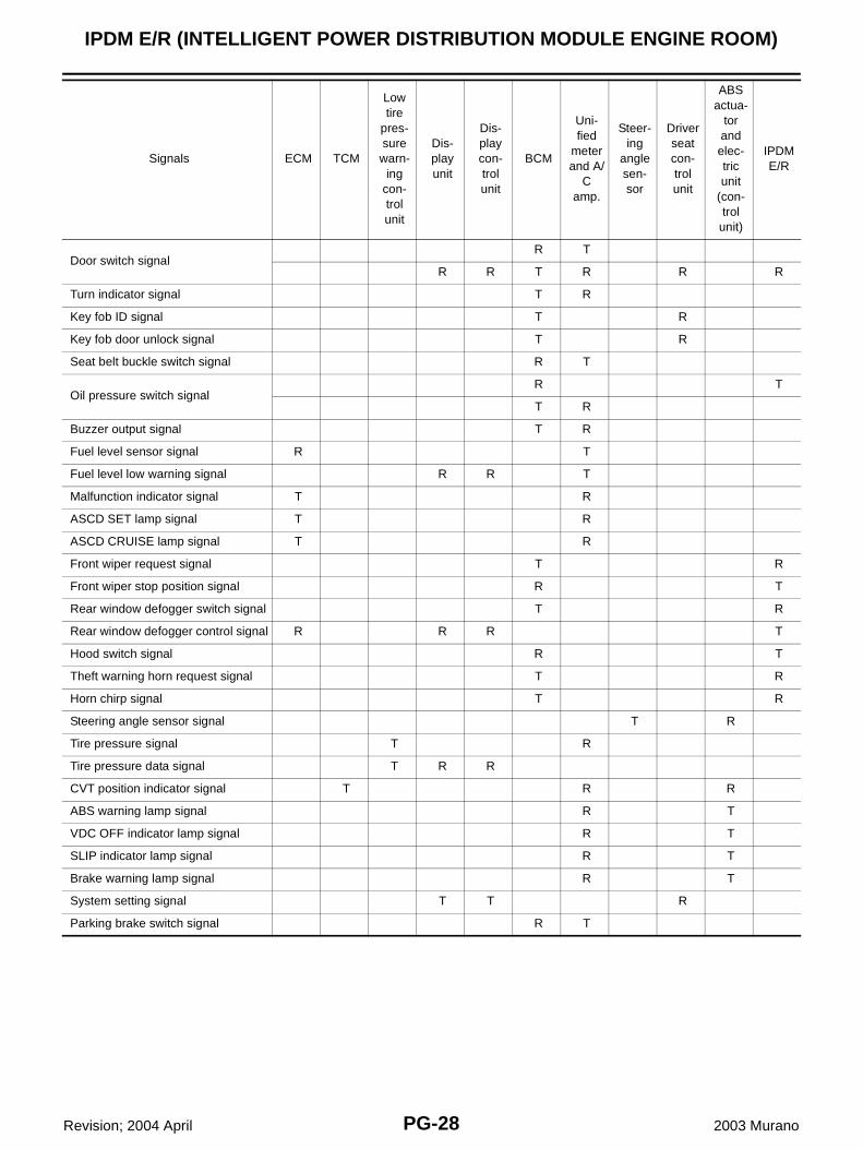
Door switch signalR T
R R T R R R
Turn indicator signal T R
Key fob ID signal T R
Key fob door unlock signal T R
Seat belt buckle switch signal R T
Oil pressure switch signalR T
T R
Buzzer output signal T R
Fuel level sensor signal R T
Fuel level low warning signal R R T
Malfunction indicator signal T R
ASCD SET lamp signal T R
ASCD CRUISE lamp signal T R
Front wiper request signal T R
Front wiper stop position signal R T
Rear window defogger switch signal T R
Rear window defogger control signal R R R T
Hood switch signal R T
Theft warning horn request signal T R
Horn chirp signal T R
Steering angle sensor signal T R
Tire pressure signal T R
Tire pressure data signal T R R
CVT position indicator signal T R R
ABS warning lamp signal R T
VDC OFF indicator lamp signal R T
SLIP indicator lamp signal R T
Brake warning lamp signal R T
System setting signal T T R
Parking brake switch signal R T
Signals ECM TCM
Low tire
pres-sure warn-
ing con-trol unit
Dis-play unit
Dis-play con-trol unit
BCM
Uni-fied
meter and A/
C amp.
Steer-ing
angle sen-sor
Driver seat con-trol unit
ABS actua-
tor and elec-tric unit
(con-trol
unit)
IPDM E/R
IPDM E/R (INTELLIGENT POWER DISTRIBUTION MODULE ENGINE ROOM)
PG-29
C
D
E
F
G
H
I
J
L
M
A
B
PG
Revision; 2004 April 2003 Murano
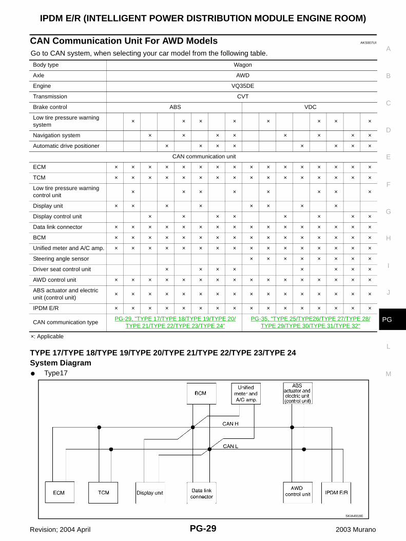
CAN Communication Unit For AWD Models AKS007UI
Go to CAN system, when selecting your car model from the following table.
×: Applicable
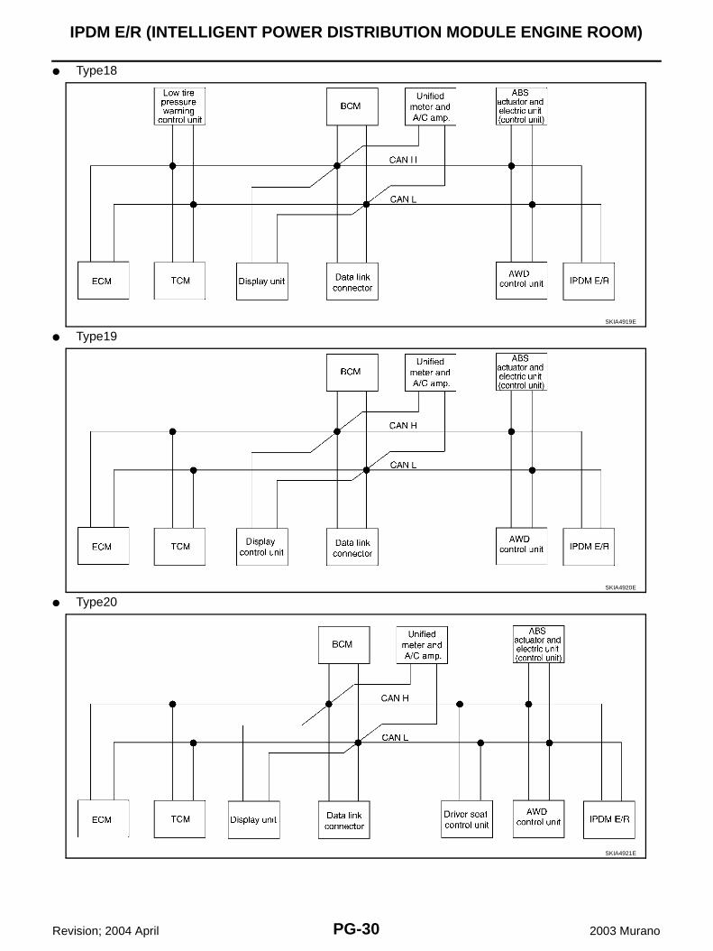
TYPE 17/TYPE 18/TYPE 19/TYPE 20/TYPE 21/TYPE 22/TYPE 23/TYPE 24System Diagram● Type17
Body type Wagon
Axle AWD
Engine VQ35DE
Transmission CVT
Brake control ABS VDC
Low tire pressure warning system
× × × × × × × ×
Navigation system × × × × × × × ×
Automatic drive positioner × × × × × × × ×
CAN communication unit
ECM × × × × × × × × × × × × × × × ×
TCM × × × × × × × × × × × × × × × ×
Low tire pressure warning control unit
× × × × × × × ×
Display unit × × × × × × × ×
Display control unit × × × × × × × ×
Data link connector × × × × × × × × × × × × × × × ×
BCM × × × × × × × × × × × × × × × ×
Unified meter and A/C amp. × × × × × × × × × × × × × × × ×
Steering angle sensor × × × × × × × ×
Driver seat control unit × × × × × × × ×
AWD control unit × × × × × × × × × × × × × × × ×
ABS actuator and electric unit (control unit)
× × × × × × × × × × × × × × × ×
IPDM E/R × × × × × × × × × × × × × × × ×
CAN communication typePG-29, "TYPE 17/TYPE 18/TYPE 19/TYPE 20/
TYPE 21/TYPE 22/TYPE 23/TYPE 24"PG-35, "TYPE 25/TYPE26/TYPE 27/TYPE 28/
TYPE 29/TYPE 30/TYPE 31/TYPE 32"
SKIA4918E
PG-30
IPDM E/R (INTELLIGENT POWER DISTRIBUTION MODULE ENGINE ROOM)
Revision; 2004 April 2003 Murano
● Type18
● Type19
● Type20
SKIA4919E
SKIA4920E
SKIA4921E
IPDM E/R (INTELLIGENT POWER DISTRIBUTION MODULE ENGINE ROOM)
PG-31
C
D
E
F
G
H
I
J
L
M
A
B
PG
Revision; 2004 April 2003 Murano
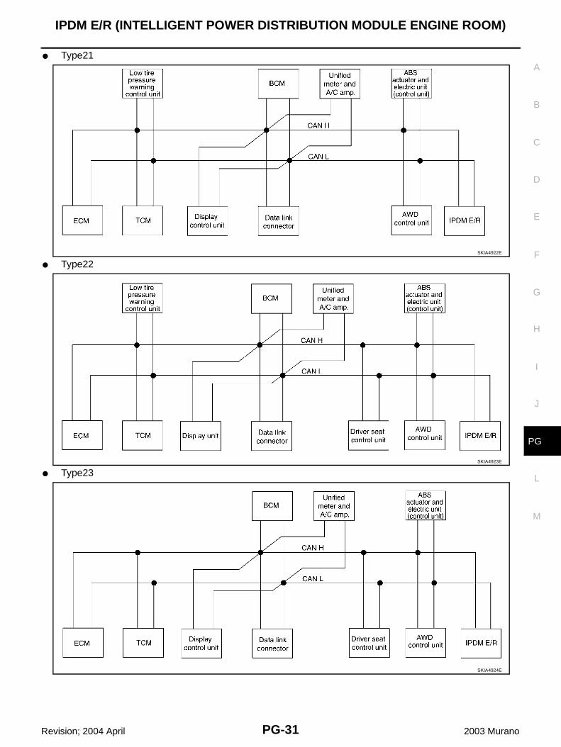
● Type21
● Type22
● Type23
SKIA4922E
SKIA4923E
SKIA4924E
PG-32
IPDM E/R (INTELLIGENT POWER DISTRIBUTION MODULE ENGINE ROOM)
Revision; 2004 April 2003 Murano
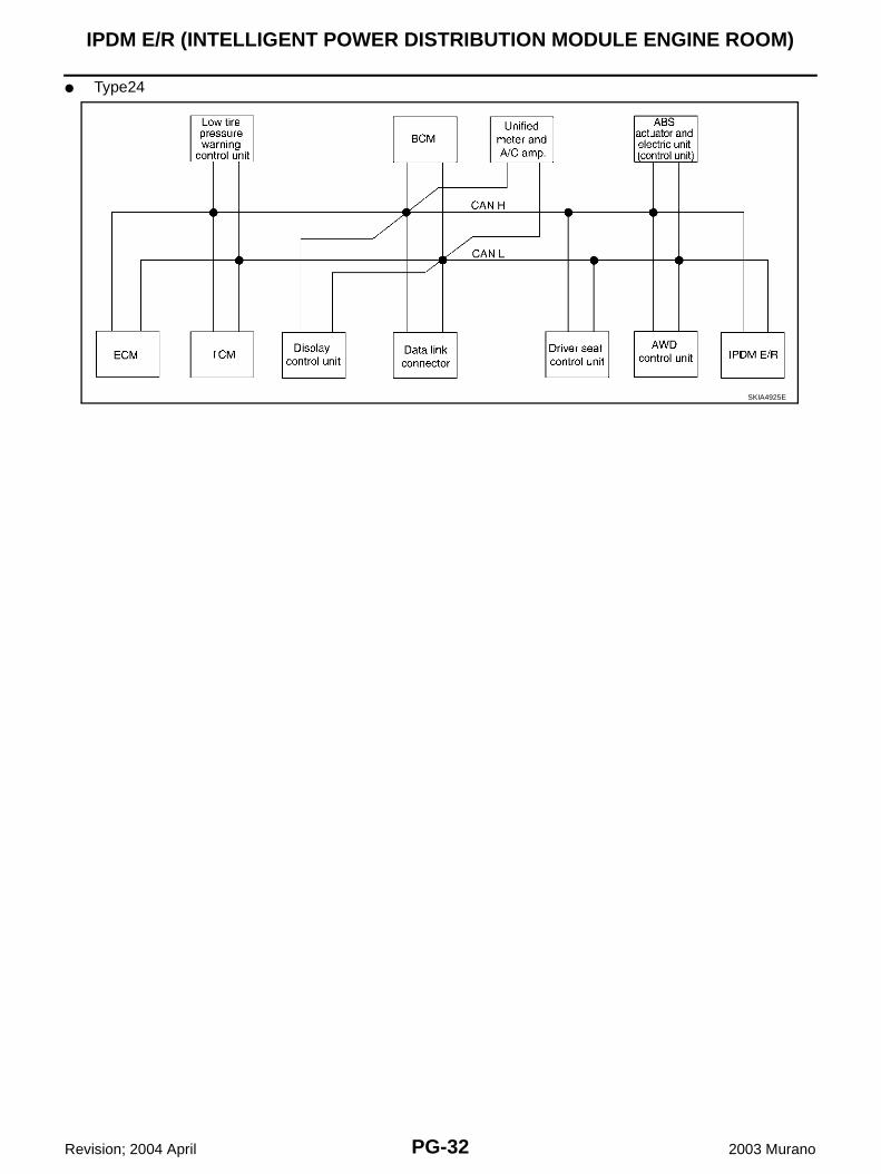
● Type24
SKIA4925E
IPDM E/R (INTELLIGENT POWER DISTRIBUTION MODULE ENGINE ROOM)
PG-33
C
D
E
F
G
H
I
J
L
M
A
B
PG
Revision; 2004 April 2003 Murano
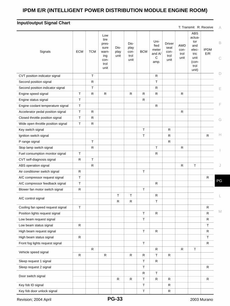
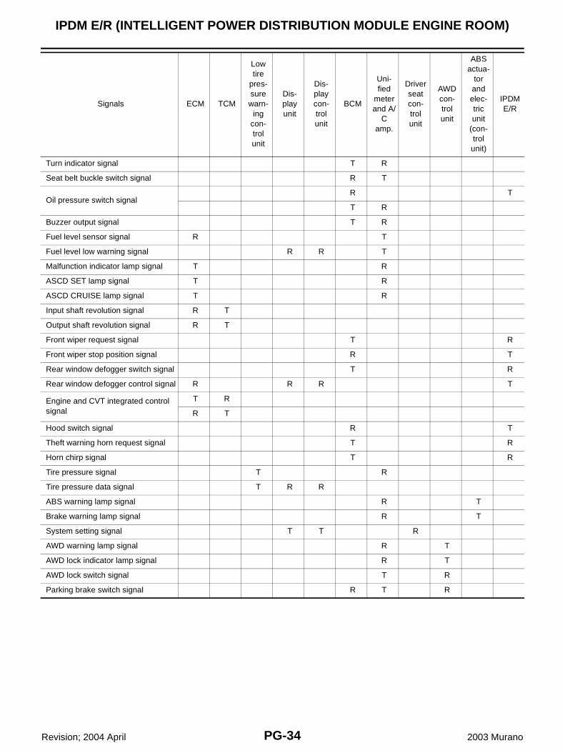
Input/output Signal ChartT: Transmit R: Receive
Signals ECM TCM
Low tire
pres-sure
warn-ing
con-trol unit
Dis-play unit
Dis-play con-trol unit
BCM
Uni-fied
meter and A/
C amp.
Driver seat con-trol unit
AWD con-trol unit
ABS actua-
tor and elec-tric unit
(con-trol
unit)
IPDM E/R
CVT position indicator signal T R
Second position signal R T
Second position indicator signal T R
Engine speed signal T R R R R R R
Engine status signal T R
Engine coolant temperature signal T R
Accelerator pedal position signal T R R
Closed throttle position signal T R
Wide open throttle position signal T R
Key switch signal T R
Ignition switch signal T R R
P range signal T R
Stop lamp switch signal R T R
Fuel consumption monitor signal T R
CVT self-diagnosis signal R T
ABS operation signal R R T
Air conditioner switch signal R T
A/C compressor request signal T R
A/C compressor feedback signal T R
Blower fan motor switch signal R T
A/C control signalT T R
R R T
Cooling fan speed request signal T R
Position lights request signal T R R
Low beam request signal T R
Low beam status signal R T
High beam request signal T R R
High beam status signal R T
Front fog lights request signal T R
Vehicle speed signalR R R T
R R R R T R
Sleep request 1 signal T R
Sleep request 2 signal T R
Door switch signalR T
R R T R R R
Key fob ID signal T R
Key fob door unlock signal T R
PG-34
IPDM E/R (INTELLIGENT POWER DISTRIBUTION MODULE ENGINE ROOM)
Revision; 2004 April 2003 Murano
Turn indicator signal T R
Seat belt buckle switch signal R T
Oil pressure switch signalR T
T R
Buzzer output signal T R
Fuel level sensor signal R T
Fuel level low warning signal R R T
Malfunction indicator lamp signal T R
ASCD SET lamp signal T R
ASCD CRUISE lamp signal T R
Input shaft revolution signal R T
Output shaft revolution signal R T
Front wiper request signal T R
Front wiper stop position signal R T
Rear window defogger switch signal T R
Rear window defogger control signal R R R T
Engine and CVT integrated control signal
T R
R T
Hood switch signal R T
Theft warning horn request signal T R
Horn chirp signal T R
Tire pressure signal T R
Tire pressure data signal T R R
ABS warning lamp signal R T
Brake warning lamp signal R T
System setting signal T T R
AWD warning lamp signal R T
AWD lock indicator lamp signal R T
AWD lock switch signal T R
Parking brake switch signal R T R
Signals ECM TCM
Low tire
pres-sure warn-
ing con-trol unit
Dis-play unit
Dis-play con-trol unit
BCM
Uni-fied
meter and A/
C amp.
Driver seat con-trol unit
AWD con-trol unit
ABS actua-
tor and elec-tric unit
(con-trol unit)
IPDM E/R
IPDM E/R (INTELLIGENT POWER DISTRIBUTION MODULE ENGINE ROOM)
PG-35
C
D
E
F
G
H
I
J
L
M
A
B
PG
Revision; 2004 April 2003 Murano
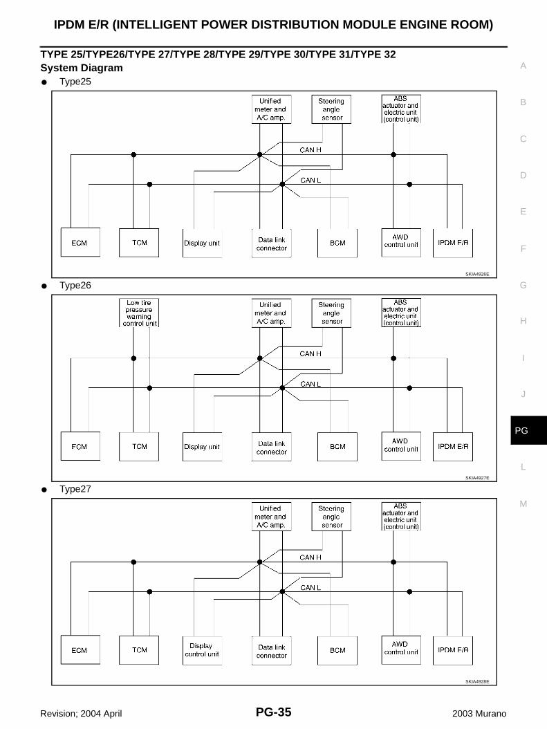
TYPE 25/TYPE26/TYPE 27/TYPE 28/TYPE 29/TYPE 30/TYPE 31/TYPE 32System Diagram● Type25
● Type26
● Type27
SKIA4926E
SKIA4927E
SKIA4928E
PG-36
IPDM E/R (INTELLIGENT POWER DISTRIBUTION MODULE ENGINE ROOM)
Revision; 2004 April 2003 Murano
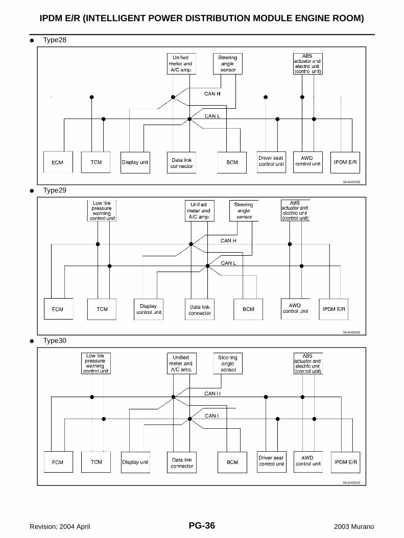
● Type28
● Type29
● Type30
SKIA4929E
SKIA4930E
SKIA4931E
IPDM E/R (INTELLIGENT POWER DISTRIBUTION MODULE ENGINE ROOM)
PG-37
C
D
E
F
G
H
I
J
L
M
A
B
PG
Revision; 2004 April 2003 Murano
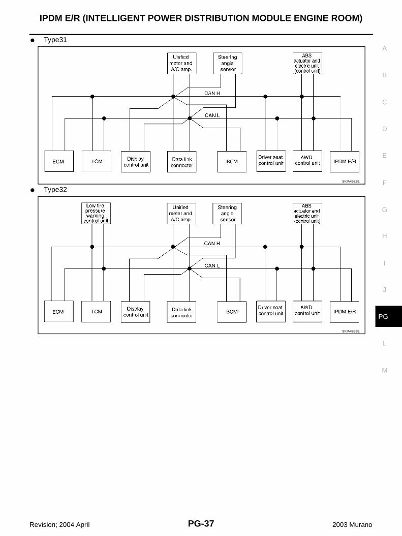
● Type31
● Type32SKIA4932E
SKIA4933E
PG-38
IPDM E/R (INTELLIGENT POWER DISTRIBUTION MODULE ENGINE ROOM)
Revision; 2004 April 2003 Murano
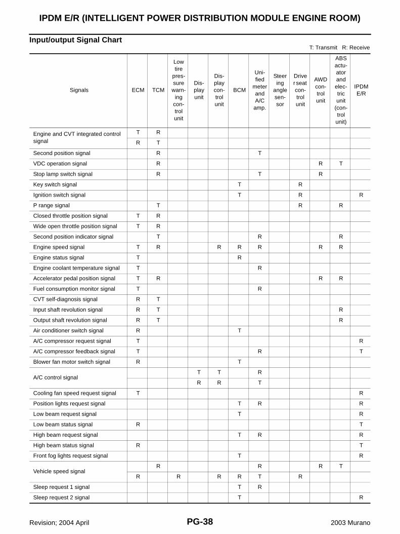
Input/output Signal ChartT: Transmit R: Receive
Signals ECM TCM
Low tire
pres-sure warn-
ing con-trol unit
Dis-play unit
Dis-play con-trol unit
BCM
Uni-fied
meter and A/C
amp.
Steering
angle sen-sor
Driver seat con-trol unit
AWD con-trol unit
ABS actu-ator and elec-tric unit
(con-trol unit)
IPDM E/R
Engine and CVT integrated control signal
T R
R T
Second position signal R T
VDC operation signal R R T
Stop lamp switch signal R T R
Key switch signal T R
Ignition switch signal T R R
P range signal T R R
Closed throttle position signal T R
Wide open throttle position signal T R
Second position indicator signal T R R
Engine speed signal T R R R R R R
Engine status signal T R
Engine coolant temperature signal T R
Accelerator pedal position signal T R R R
Fuel consumption monitor signal T R
CVT self-diagnosis signal R T
Input shaft revolution signal R T R
Output shaft revolution signal R T R
Air conditioner switch signal R T
A/C compressor request signal T R
A/C compressor feedback signal T R T
Blower fan motor switch signal R T
A/C control signalT T R
R R T
Cooling fan speed request signal T R
Position lights request signal T R R
Low beam request signal T R
Low beam status signal R T
High beam request signal T R R
High beam status signal R T
Front fog lights request signal T R
Vehicle speed signalR R R T
R R R R T R
Sleep request 1 signal T R
Sleep request 2 signal T R
IPDM E/R (INTELLIGENT POWER DISTRIBUTION MODULE ENGINE ROOM)
PG-39
C
D
E
F
G
H
I
J
L
M
A
B
PG
Revision; 2004 April 2003 Murano
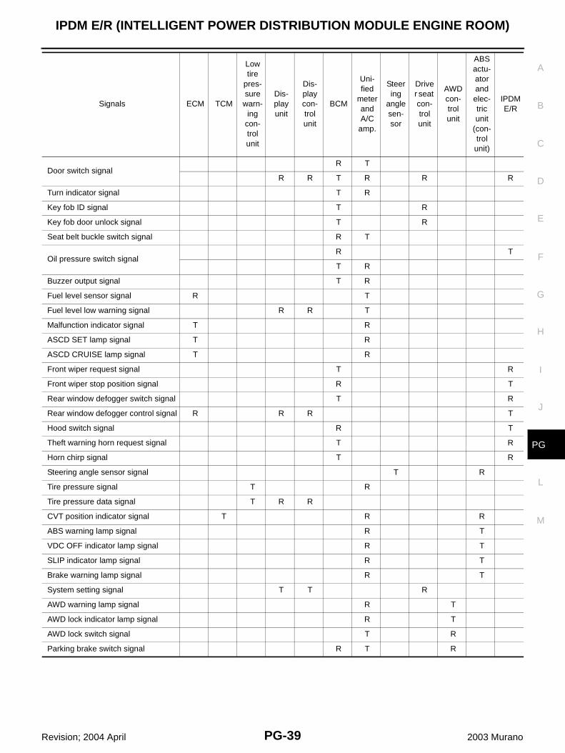
Door switch signalR T
R R T R R R
Turn indicator signal T R
Key fob ID signal T R
Key fob door unlock signal T R
Seat belt buckle switch signal R T
Oil pressure switch signalR T
T R
Buzzer output signal T R
Fuel level sensor signal R T
Fuel level low warning signal R R T
Malfunction indicator signal T R
ASCD SET lamp signal T R
ASCD CRUISE lamp signal T R
Front wiper request signal T R
Front wiper stop position signal R T
Rear window defogger switch signal T R
Rear window defogger control signal R R R T
Hood switch signal R T
Theft warning horn request signal T R
Horn chirp signal T R
Steering angle sensor signal T R
Tire pressure signal T R
Tire pressure data signal T R R
CVT position indicator signal T R R
ABS warning lamp signal R T
VDC OFF indicator lamp signal R T
SLIP indicator lamp signal R T
Brake warning lamp signal R T
System setting signal T T R
AWD warning lamp signal R T
AWD lock indicator lamp signal R T
AWD lock switch signal T R
Parking brake switch signal R T R
Signals ECM TCM
Low tire
pres-sure
warn-ing
con-trol unit
Dis-play unit
Dis-play con-trol unit
BCM
Uni-fied
meter and A/C
amp.
Steering
angle sen-sor
Driver seat con-trol unit
AWD con-trol unit
ABS actu-ator and elec-tric unit
(con-trol
unit)
IPDM E/R

PG-40
IPDM E/R (INTELLIGENT POWER DISTRIBUTION MODULE ENGINE ROOM)
Revision; 2004 April 2003 Murano
Function of Detecting Ignition Relay Malfunction AKS004CM
● When contact point of integrated ignition relay is stuck and cannot be turned OFF, IPDM E/R turns ON tailand parking lamps for 10 minutes to indicate IPDM E/R malfunction.NOTE:When the ignition switch is turned ON, the tail lamp is OFF.
IPDM E/R (INTELLIGENT POWER DISTRIBUTION MODULE ENGINE ROOM)
PG-41
C
D
E
F
G
H
I
J
L
M
A
B
PG
Revision; 2004 April 2003 Murano
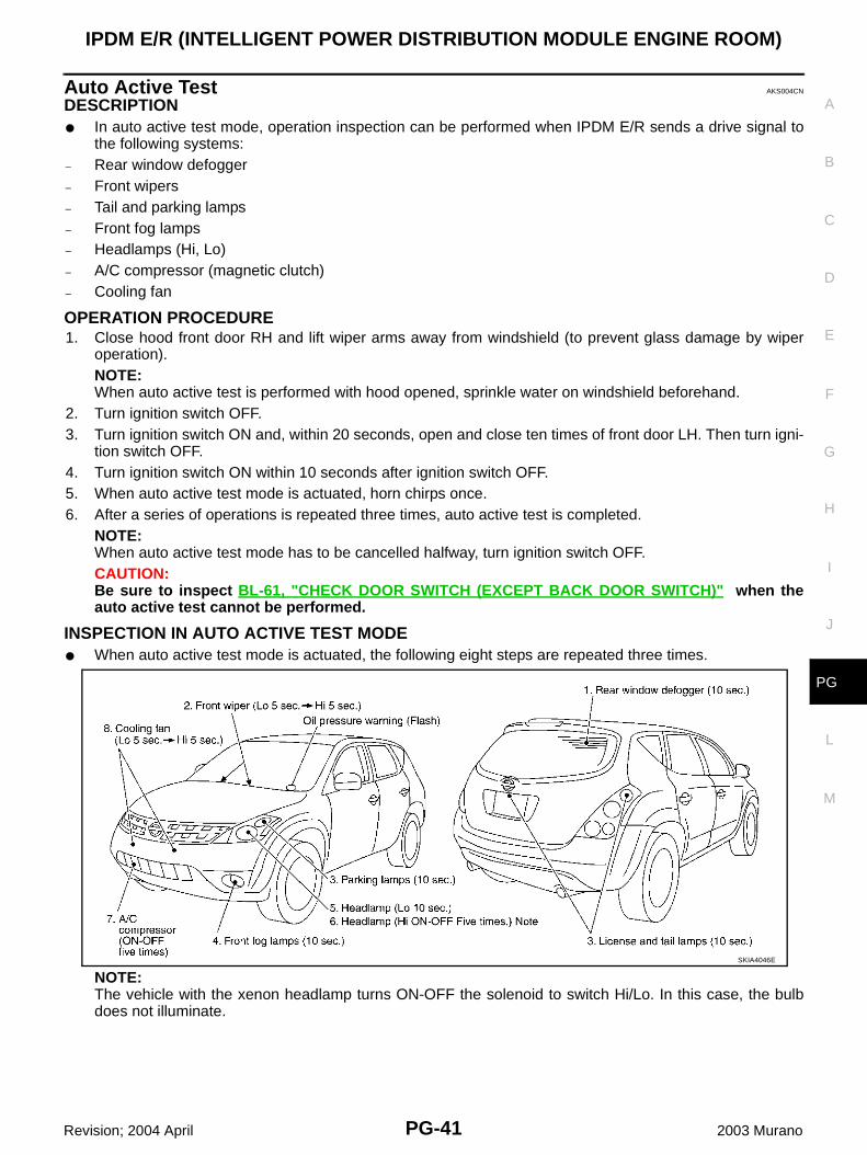
Auto Active Test AKS004CN
DESCRIPTION● In auto active test mode, operation inspection can be performed when IPDM E/R sends a drive signal to
the following systems:– Rear window defogger– Front wipers– Tail and parking lamps– Front fog lamps– Headlamps (Hi, Lo)– A/C compressor (magnetic clutch)– Cooling fan
OPERATION PROCEDURE1. Close hood front door RH and lift wiper arms away from windshield (to prevent glass damage by wiper
operation).NOTE:When auto active test is performed with hood opened, sprinkle water on windshield beforehand.
2. Turn ignition switch OFF.3. Turn ignition switch ON and, within 20 seconds, open and close ten times of front door LH. Then turn igni-
tion switch OFF.4. Turn ignition switch ON within 10 seconds after ignition switch OFF. 5. When auto active test mode is actuated, horn chirps once.6. After a series of operations is repeated three times, auto active test is completed.
NOTE:When auto active test mode has to be cancelled halfway, turn ignition switch OFF.CAUTION:Be sure to inspect BL-61, "CHECK DOOR SWITCH (EXCEPT BACK DOOR SWITCH)" when theauto active test cannot be performed.
INSPECTION IN AUTO ACTIVE TEST MODE● When auto active test mode is actuated, the following eight steps are repeated three times.
NOTE:The vehicle with the xenon headlamp turns ON-OFF the solenoid to switch Hi/Lo. In this case, the bulbdoes not illuminate.
SKIA4046E
PG-42
IPDM E/R (INTELLIGENT POWER DISTRIBUTION MODULE ENGINE ROOM)
Revision; 2004 April 2003 Murano
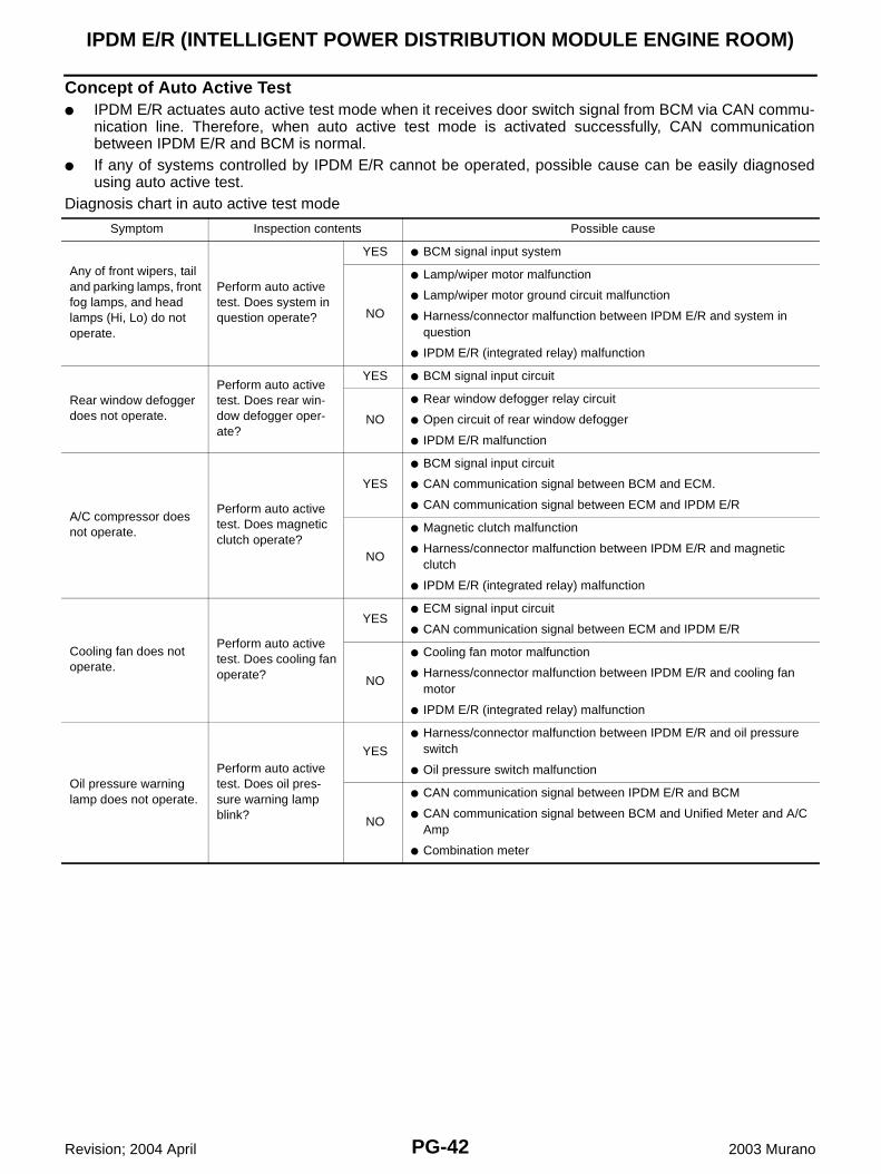
Concept of Auto Active Test● IPDM E/R actuates auto active test mode when it receives door switch signal from BCM via CAN commu-
nication line. Therefore, when auto active test mode is activated successfully, CAN communicationbetween IPDM E/R and BCM is normal.
● If any of systems controlled by IPDM E/R cannot be operated, possible cause can be easily diagnosedusing auto active test.
Diagnosis chart in auto active test mode
Symptom Inspection contents Possible cause
Any of front wipers, tail and parking lamps, front fog lamps, and head lamps (Hi, Lo) do not operate.
Perform auto active test. Does system in question operate?
YES ● BCM signal input system
NO
● Lamp/wiper motor malfunction
● Lamp/wiper motor ground circuit malfunction
● Harness/connector malfunction between IPDM E/R and system in question
● IPDM E/R (integrated relay) malfunction
Rear window defogger does not operate.
Perform auto active test. Does rear win-dow defogger oper-ate?
YES ● BCM signal input circuit
NO
● Rear window defogger relay circuit
● Open circuit of rear window defogger
● IPDM E/R malfunction
A/C compressor does not operate.
Perform auto active test. Does magnetic clutch operate?
YES
● BCM signal input circuit
● CAN communication signal between BCM and ECM.
● CAN communication signal between ECM and IPDM E/R
NO
● Magnetic clutch malfunction
● Harness/connector malfunction between IPDM E/R and magnetic clutch
● IPDM E/R (integrated relay) malfunction
Cooling fan does not operate.
Perform auto active test. Does cooling fan operate?
YES● ECM signal input circuit
● CAN communication signal between ECM and IPDM E/R
NO
● Cooling fan motor malfunction
● Harness/connector malfunction between IPDM E/R and cooling fan motor
● IPDM E/R (integrated relay) malfunction
Oil pressure warning lamp does not operate.
Perform auto active test. Does oil pres-sure warning lamp blink?
YES
● Harness/connector malfunction between IPDM E/R and oil pressure switch
● Oil pressure switch malfunction
NO
● CAN communication signal between IPDM E/R and BCM
● CAN communication signal between BCM and Unified Meter and A/C Amp
● Combination meter
IPDM E/R (INTELLIGENT POWER DISTRIBUTION MODULE ENGINE ROOM)
PG-43
C
D
E
F
G
H
I
J
L
M
A
B
PG
Revision; 2004 April 2003 Murano
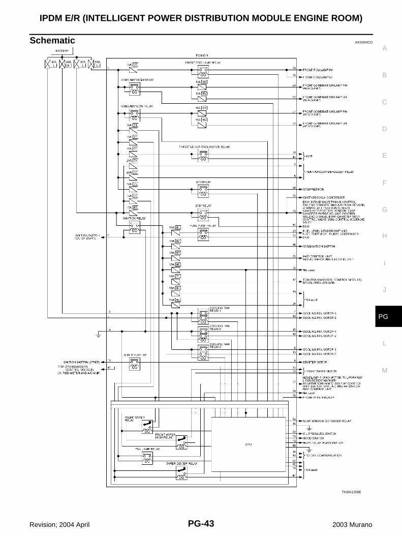
Schematic AKS004CO
TKWA1258E
PG-44
IPDM E/R (INTELLIGENT POWER DISTRIBUTION MODULE ENGINE ROOM)
Revision; 2004 April 2003 Murano
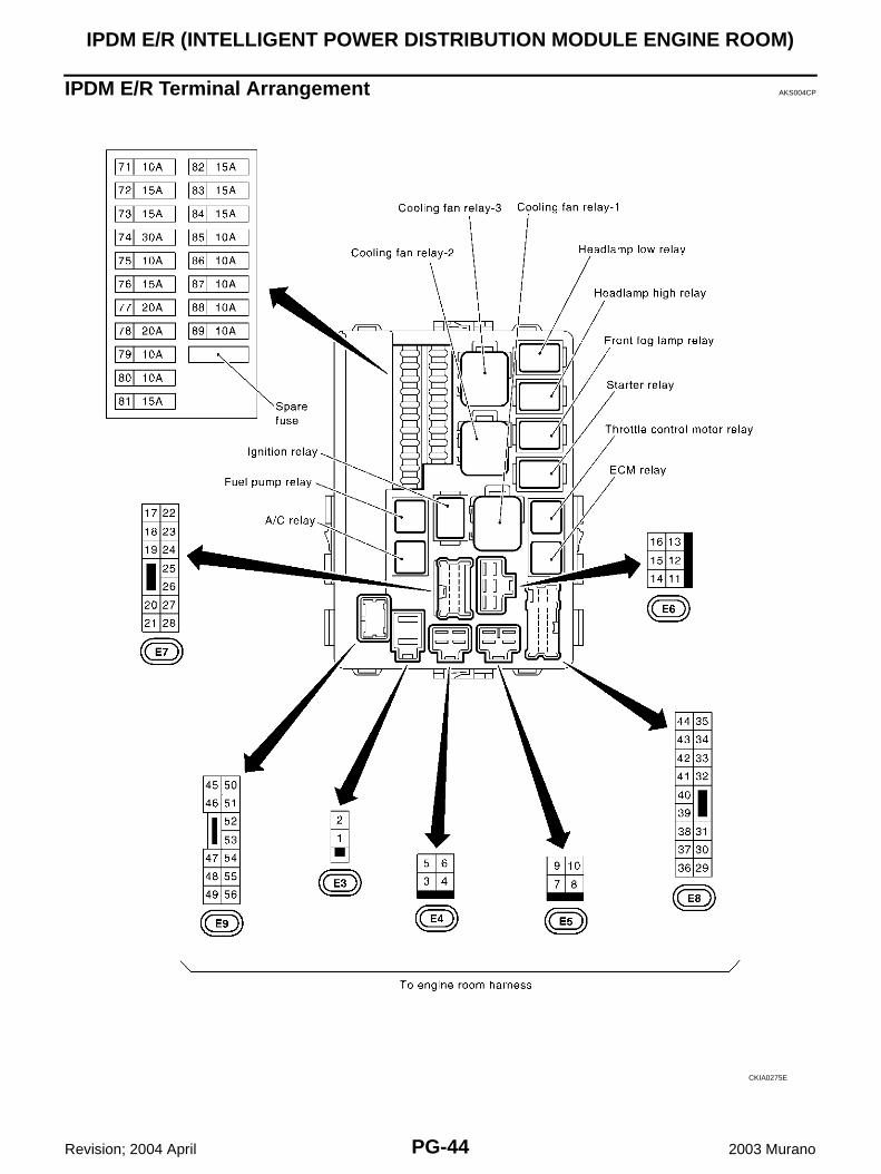
IPDM E/R Terminal Arrangement AKS004CP
CKIA0275E
IPDM E/R (INTELLIGENT POWER DISTRIBUTION MODULE ENGINE ROOM)
PG-45
C
D
E
F
G
H
I
J
L
M
A
B
PG
Revision; 2004 April 2003 Murano
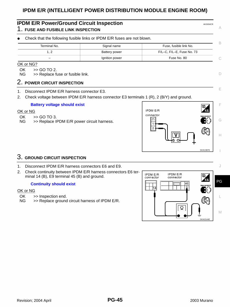
IPDM E/R Power/Ground Circuit Inspection AKS004CR
1. FUSE AND FUSIBLE LINK INSPECTION
● Check that the following fusible links or IPDM E/R fuses are not blown.
OK or NG?OK >> GO TO 2.NG >> Replace fuse or fusible link.
2. POWER CIRCUIT INSPECTION
1. Disconnect IPDM E/R harness connector E3.2. Check voltage between IPDM E/R harness connector E3 terminals 1 (R), 2 (B/Y) and ground.
OK or NGOK >> GO TO 3.NG >> Replace IPDM E/R power circuit harness.
3. GROUND CIRCUIT INSPECTION
1. Disconnect IPDM E/R harness connectors E6 and E9.2. Check continuity between IPDM E/R harness connectors E6 ter-
minal 14 (B), E9 terminal 45 (B) and ground.
OK or NGOK >> Inspection end.NG >> Replace ground circuit harness of IPDM E/R.
Terminal No. Signal name Fuse, fusible link No.
1, 2 Battery power F/L–C, F/L–E, Fuse No. 73
– Ignition power Fuse No. 80
Battery voltage should exist
SKIA1987E
Continuity should exist
SKIA3144E
PG-46
IPDM E/R (INTELLIGENT POWER DISTRIBUTION MODULE ENGINE ROOM)
Revision; 2004 April 2003 Murano
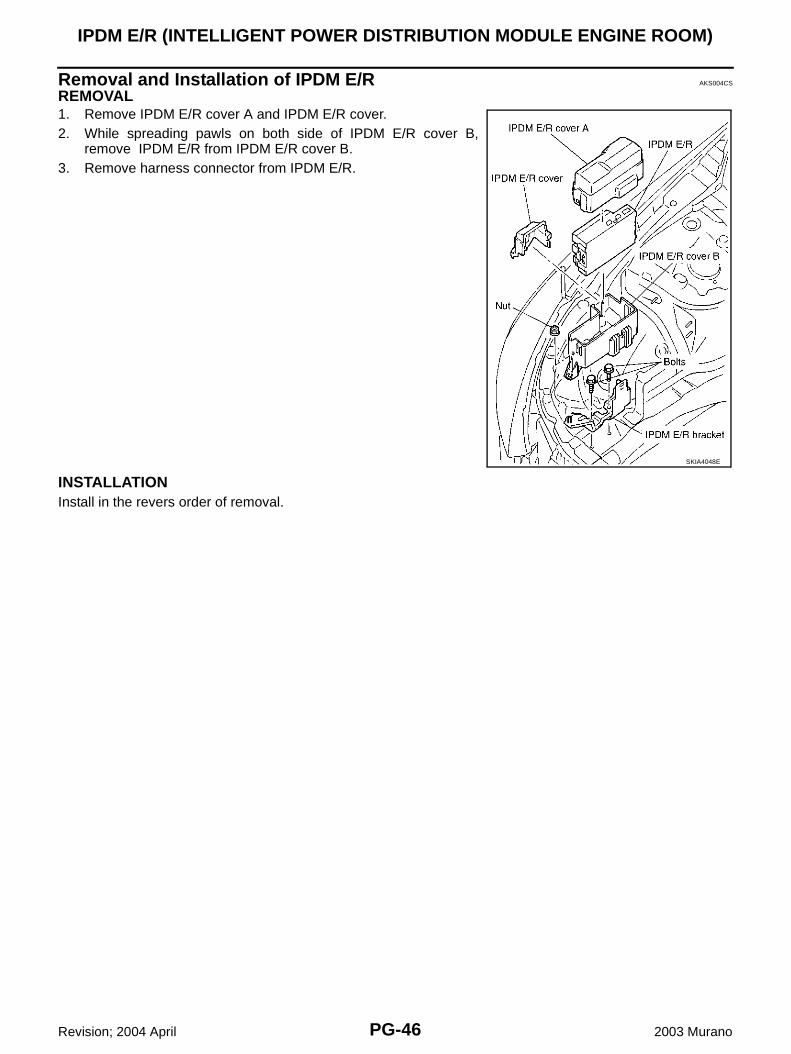
Removal and Installation of IPDM E/R AKS004CS
REMOVAL1. Remove IPDM E/R cover A and IPDM E/R cover. 2. While spreading pawls on both side of IPDM E/R cover B,
remove IPDM E/R from IPDM E/R cover B.3. Remove harness connector from IPDM E/R.
INSTALLATIONInstall in the revers order of removal.
SKIA4048E
GROUND
PG-47
C
D
E
F
G
H
I
J
L
M
A
B
PG
Revision; 2004 April 2003 Murano
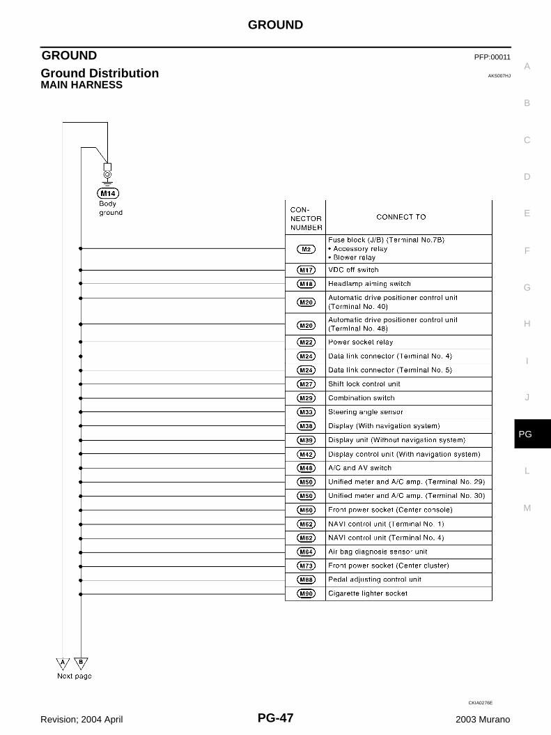
GROUND PFP:00011
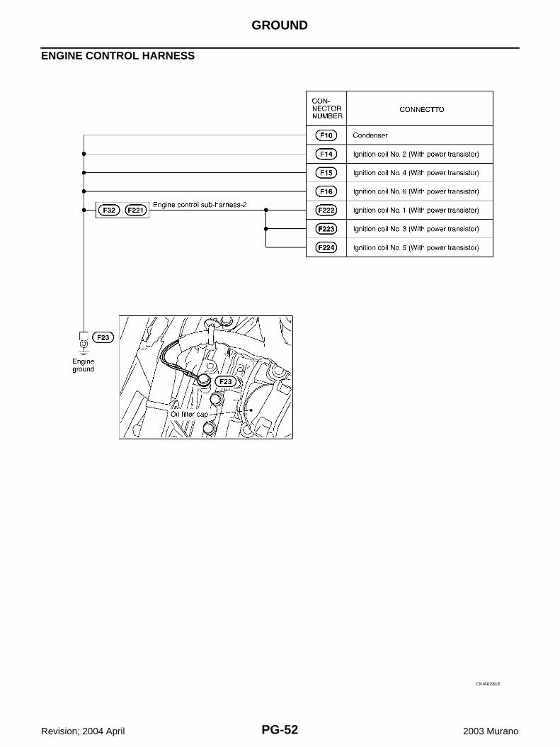
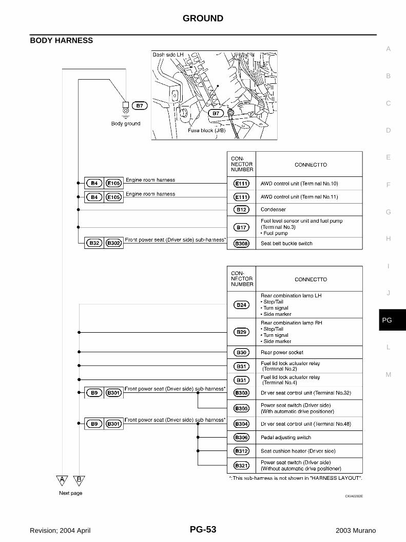
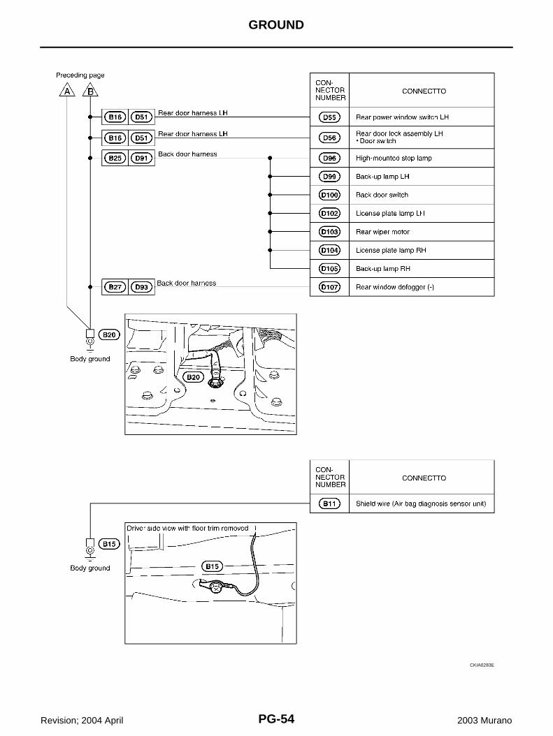
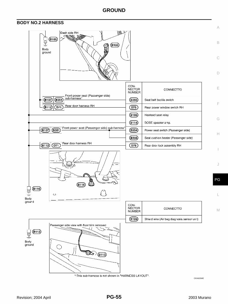
Ground Distribution AKS007HJ
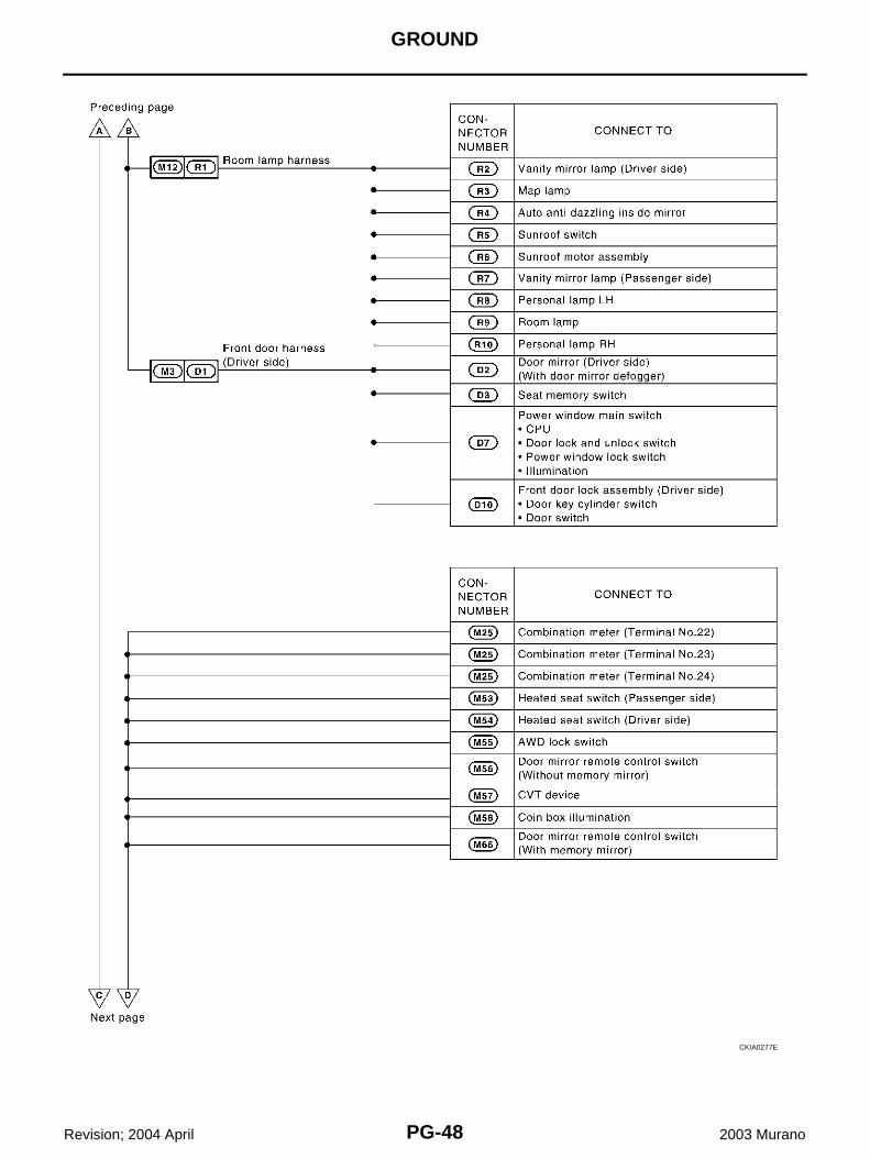
MAIN HARNESS
CKIA0276E
PG-48
GROUND
Revision; 2004 April 2003 Murano
CKIA0277E

GROUND
PG-49
C
D
E
F
G
H
I
J
L
M
A
B
PG
Revision; 2004 April 2003 Murano
CKIA0318E
PG-50
GROUND
Revision; 2004 April 2003 Murano
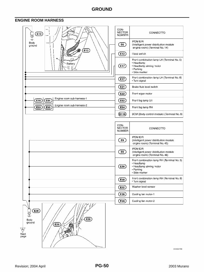
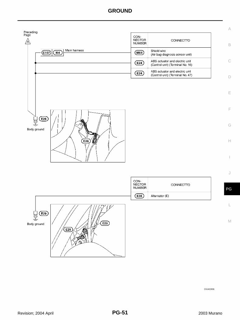
ENGINE ROOM HARNESS
CKIA0279E
GROUND
PG-51
C
D
E
F
G
H
I
J
L
M
A
B
PG
Revision; 2004 April 2003 Murano
CKIA0280E
PG-52
GROUND
Revision; 2004 April 2003 Murano
ENGINE CONTROL HARNESS
CKIA0281E
GROUND
PG-53
C
D
E
F
G
H
I
J
L
M
A
B
PG
Revision; 2004 April 2003 Murano
BODY HARNESS
CKIA0282E
PG-54
GROUND
Revision; 2004 April 2003 Murano
CKIA0283E
GROUND
PG-55
C
D
E
F
G
H
I
J
L
M
A
B
PG
Revision; 2004 April 2003 Murano
BODY NO.2 HARNESS
CKIA0284E
PG-56
HARNESS
Revision; 2004 April 2003 Murano
HARNESS PFP:00011
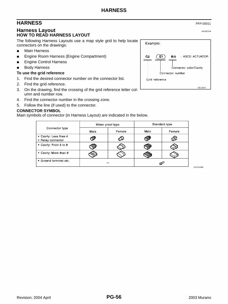
Harness Layout AKS007HK
HOW TO READ HARNESS LAYOUTThe following Harness Layouts use a map style grid to help locateconnectors on the drawings:● Main Harness● Engine Room Harness (Engine Compartment)● Engine Control Harness● Body HarnessTo use the grid reference1. Find the desired connector number on the connector list.2. Find the grid reference.3. On the drawing, find the crossing of the grid reference letter col-
umn and number row.4. Find the connector number in the crossing zone.5. Follow the line (if used) to the connector.CONNECTOR SYMBOLMain symbols of connector (in Harness Layout) are indicated in the below.
SEL252V
CKIT0108E
HARNESS
PG-57
C
D
E
F
G
H
I
J
L
M
A
B
PG
Revision; 2004 April 2003 Murano
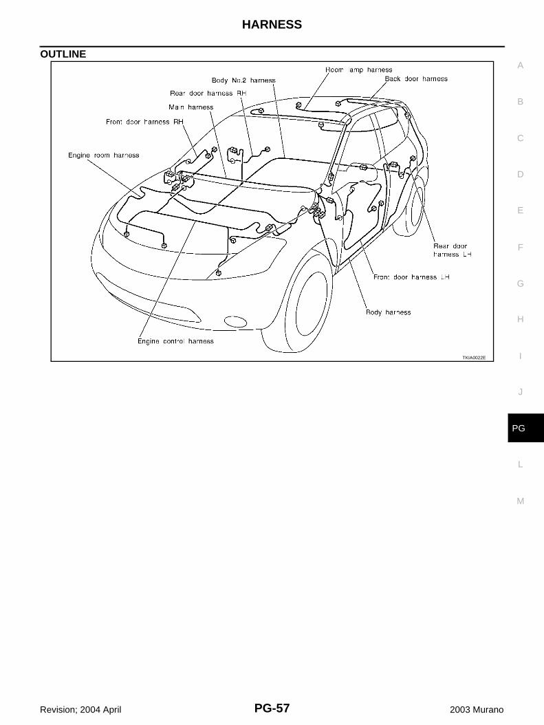
OUTLINE
TKIA0022E
PG-58
HARNESS
Revision; 2004 April 2003 Murano
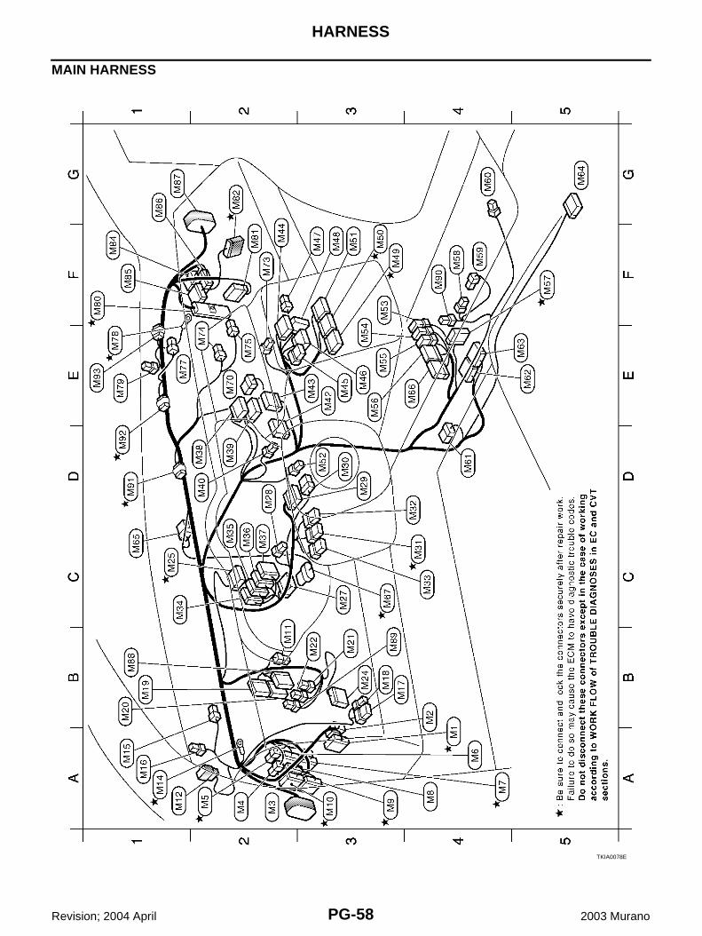
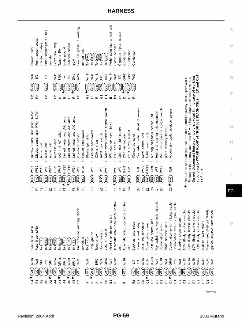
MAIN HARNESS
TKIA0078E
HARNESS
PG-59
C
D
E
F
G
H
I
J
L
M
A
B
PG
Revision; 2004 April 2003 Murano
TKIA0079E
PG-60
HARNESS
Revision; 2004 April 2003 Murano
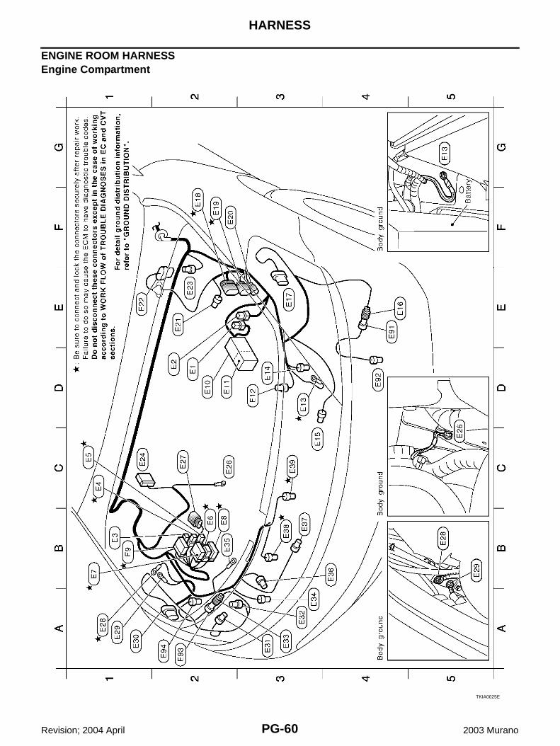
ENGINE ROOM HARNESSEngine Compartment
TKIA0025E
HARNESS
PG-61
C
D
E
F
G
H
I
J
L
M
A
B
PG
Revision; 2004 April 2003 Murano
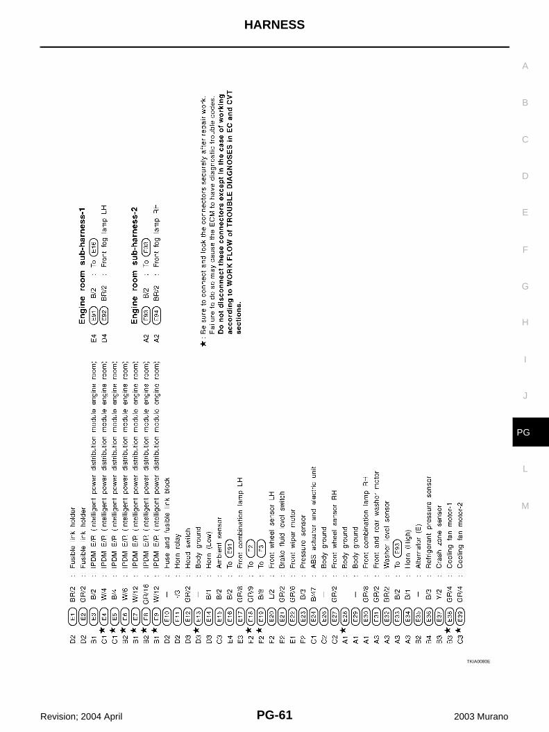
TKIA0080E
PG-62
HARNESS
Revision; 2004 April 2003 Murano
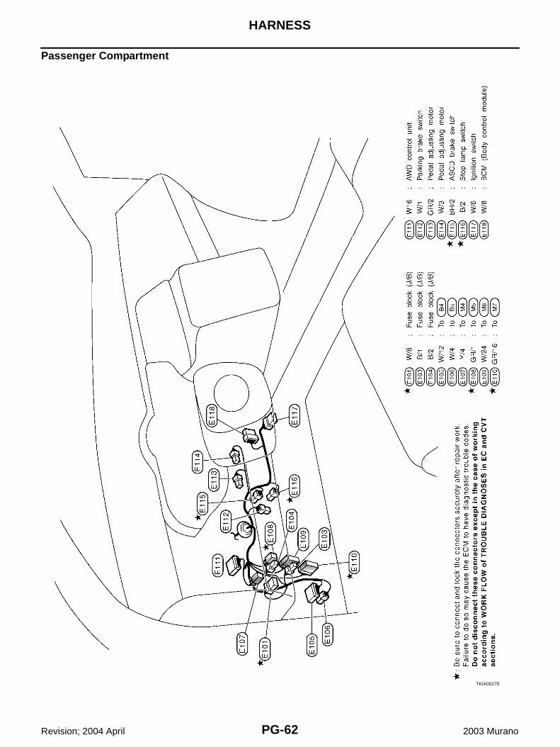
Passenger Compartment
TKIA0027E
HARNESS
PG-63
C
D
E
F
G
H
I
J
L
M
A
B
PG
Revision; 2004 April 2003 Murano
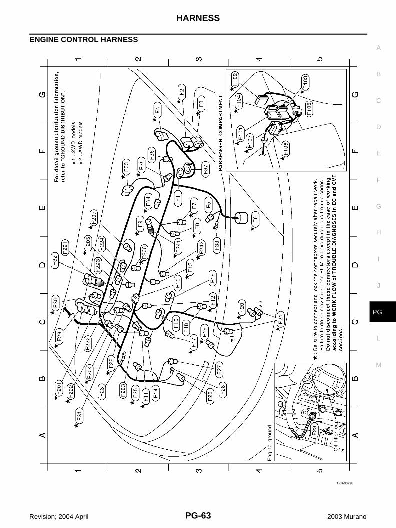
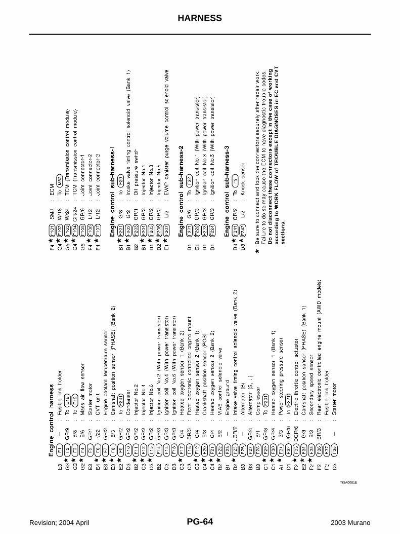
ENGINE CONTROL HARNESS
TKIA0029E
PG-64
HARNESS
Revision; 2004 April 2003 Murano
TKIA0081E
HARNESS
PG-65
C
D
E
F
G
H
I
J
L
M
A
B
PG
Revision; 2004 April 2003 Murano
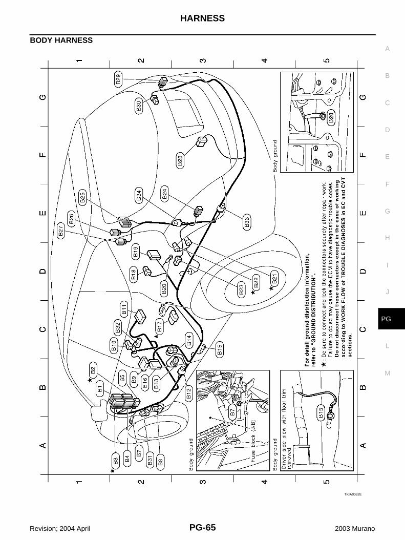
BODY HARNESS
TKIA0082E
PG-66
HARNESS
Revision; 2004 April 2003 Murano
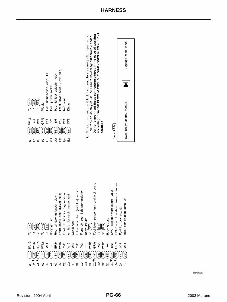
TKIA0032E
HARNESS
PG-67
C
D
E
F
G
H
I
J
L
M
A
B
PG
Revision; 2004 April 2003 Murano
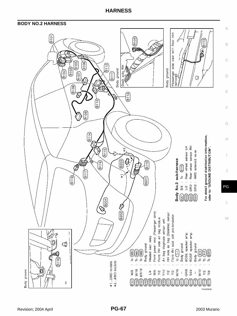
BODY NO.2 HARNESS
TKIA0083E
PG-68
HARNESS
Revision; 2004 April 2003 Murano
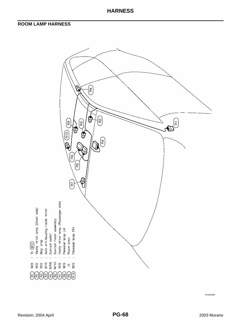
ROOM LAMP HARNESS
TKIA0035E
HARNESS
PG-69
C
D
E
F
G
H
I
J
L
M
A
B
PG
Revision; 2004 April 2003 Murano
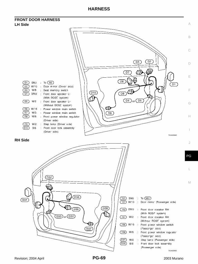
FRONT DOOR HARNESS LH Side
RH SideTKIA0084E
TKIA0085E
PG-70
HARNESS
Revision; 2004 April 2003 Murano
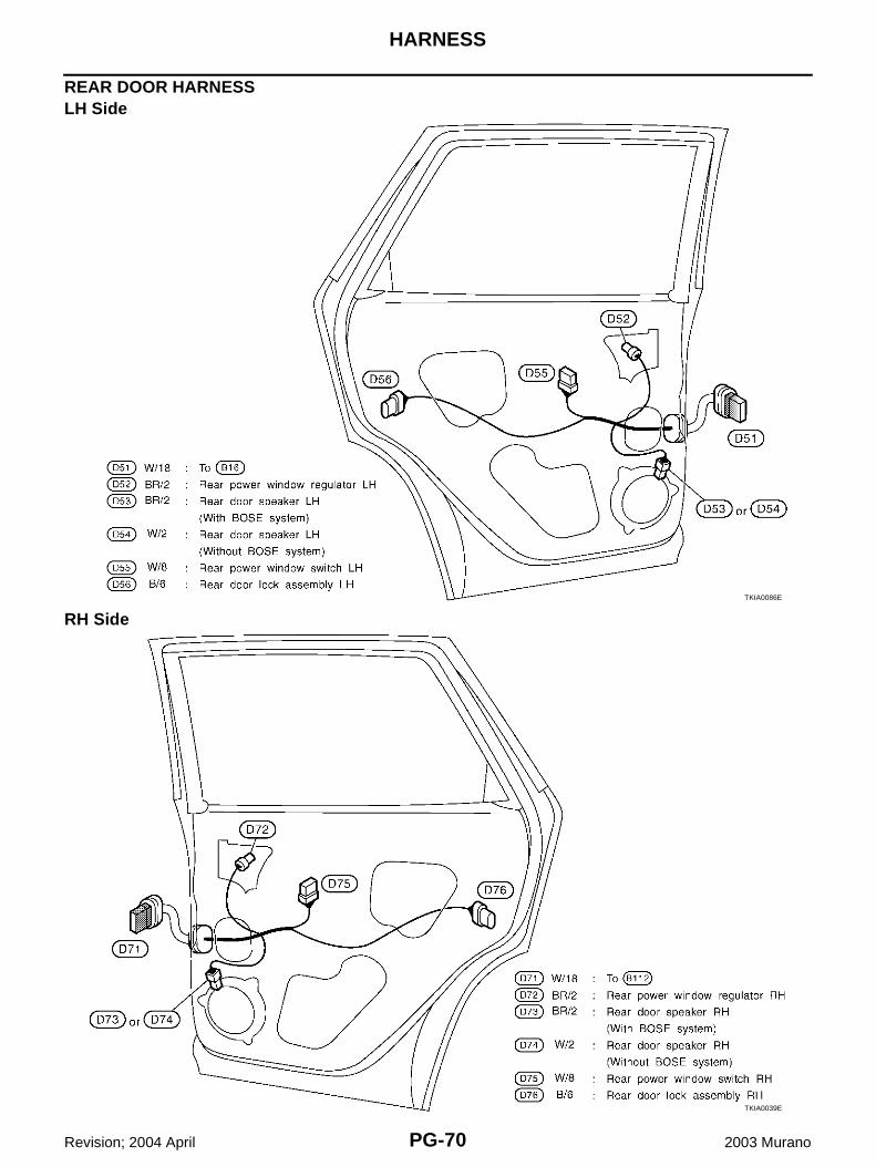
REAR DOOR HARNESSLH Side
RH SideTKIA0086E
TKIA0039E
HARNESS
PG-71
C
D
E
F
G
H
I
J
L
M
A
B
PG
Revision; 2004 April 2003 Murano
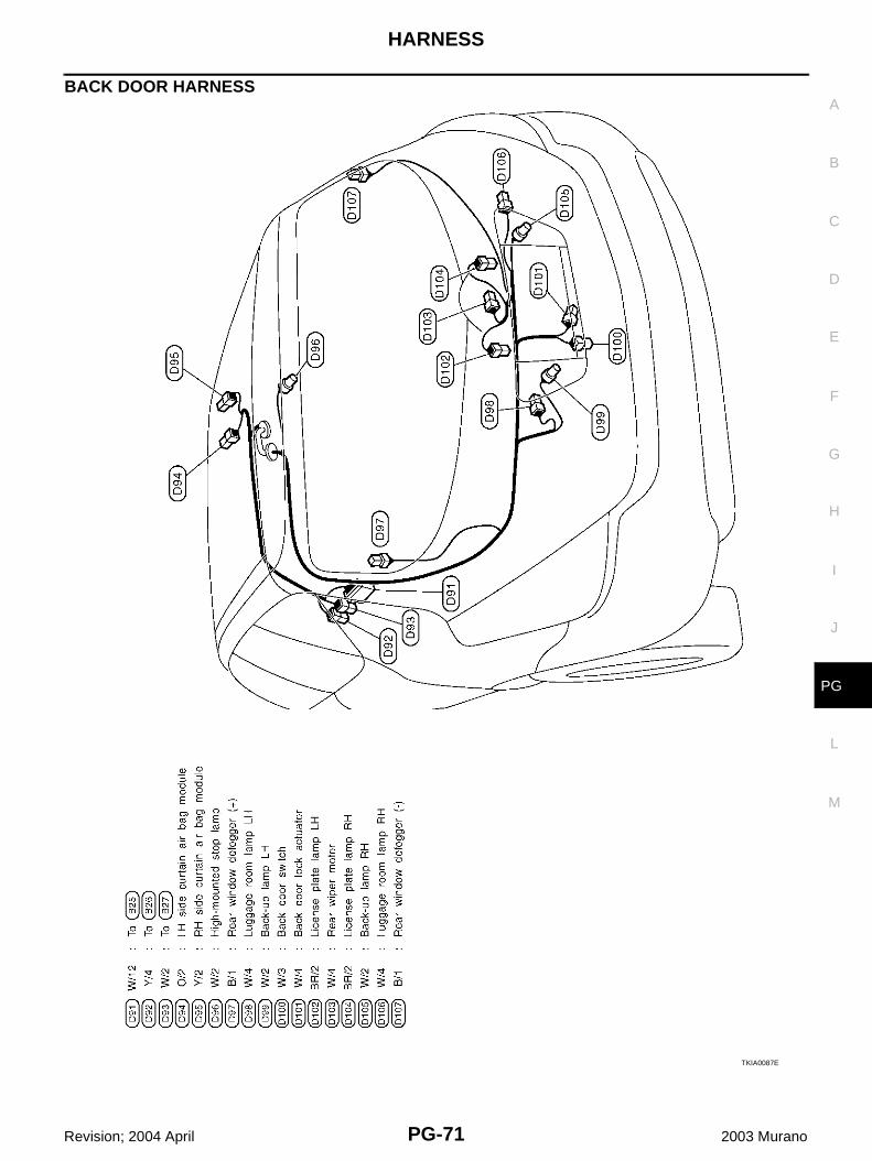
BACK DOOR HARNESS
TKIA0087E
PG-72
HARNESS
Revision; 2004 April 2003 Murano
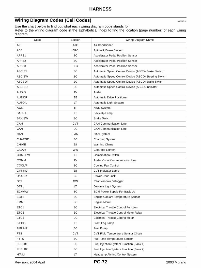
Wiring Diagram Codes (Cell Codes) AKS007HU
Use the chart below to find out what each wiring diagram code stands for.Refer to the wiring diagram code in the alphabetical index to find the location (page number) of each wiringdiagram.
Code Section Wiring Diagram Name
A/C ATC Air Conditioner
ABS BRC Anti-lock Brake System
APPS1 EC Accelerator Pedal Position Sensor
APPS2 EC Accelerator Pedal Position Sensor
APPS3 EC Accelerator Pedal Position Sensor
ASC/BS EC Automatic Speed Control Device (ASCD) Brake Switch
ASC/SW EC Automatic Speed Control Device (ASCD) Steering Switch
ASCBOF EC Automatic Speed Control Device (ASCD) Brake Switch
ASCIND EC Automatic Speed Control Device (ASCD) Indicator
AUDIO AV Audio
AUT/DP SE Automatic Drive Positioner
AUTO/L LT Automatic Light System
AWD TF AWD System
BACK/L LT Back-Up Lamp
BRK/SW EC Brake Switch
CAN CVT CAN Communication Line
CAN EC CAN Communication Line
CAN LAN CAN System
CHARGE SC Charging System
CHIME DI Warning Chime
CIGAR WW Cigarette Lighter
COMBSW LT Combination Switch
COMM AV Audio Visual Communication Line
COOL/F EC Cooling Fan Control
CVTIND DI CVT Indicator Lamp
D/LOCK BL Power Door Lock
DEF GW Rear Window Defogger
DTRL LT Daytime Light System
ECM/PW EC ECM Power Supply For Back-Up
ECTS EC Engine Coolant Temperature Sensor
EMNT EC Engine Mount
ETC1 EC Electrical Throttle Control Function
ETC2 EC Electrical Throttle Control Motor Relay
ETC3 EC Electrical Throttle Control Motor
F/FOG LT Front Fog Lamp
F/PUMP EC Fuel Pump
FTS CVT CVT Fluid Temperature Sensor Circuit
FTTS EC Fuel Tank Temperature Sensor
FUELB1 EC Fuel Injection System Function (Bank 1)
FUELB2 EC Fuel Injection System Function (Bank 2)
H/AIM LT Headlamp Aiming Control System
HARNESS
PG-73
C
D
E
F
G
H
I
J
L
M
A
B
PG
Revision; 2004 April 2003 Murano
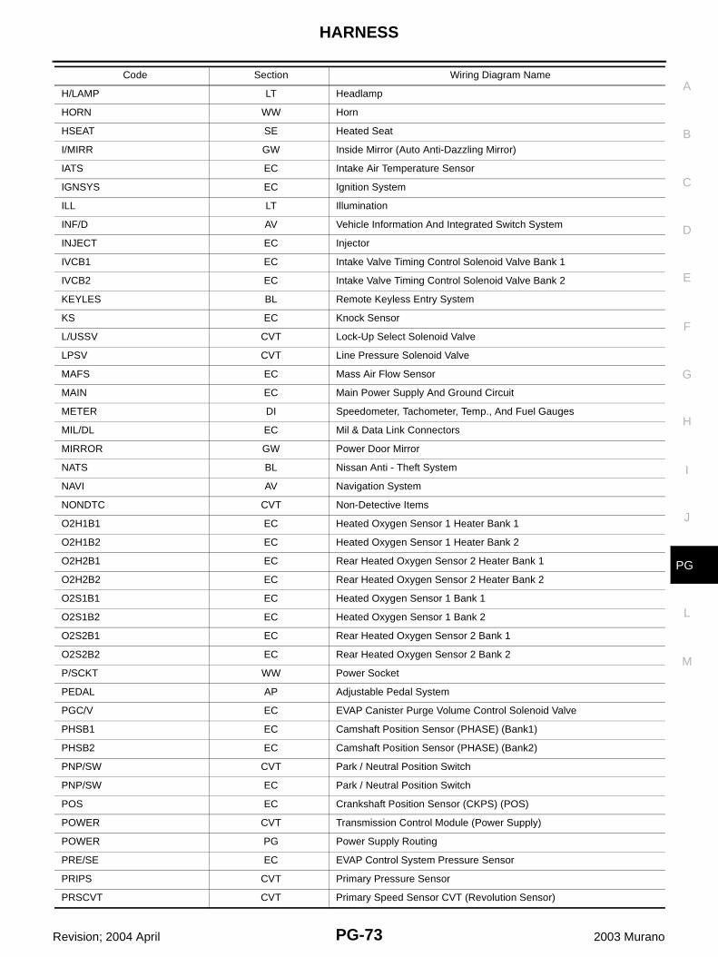
H/LAMP LT Headlamp
HORN WW Horn
HSEAT SE Heated Seat
I/MIRR GW Inside Mirror (Auto Anti-Dazzling Mirror)
IATS EC Intake Air Temperature Sensor
IGNSYS EC Ignition System
ILL LT Illumination
INF/D AV Vehicle Information And Integrated Switch System
INJECT EC Injector
IVCB1 EC Intake Valve Timing Control Solenoid Valve Bank 1
IVCB2 EC Intake Valve Timing Control Solenoid Valve Bank 2
KEYLES BL Remote Keyless Entry System
KS EC Knock Sensor
L/USSV CVT Lock-Up Select Solenoid Valve
LPSV CVT Line Pressure Solenoid Valve
MAFS EC Mass Air Flow Sensor
MAIN EC Main Power Supply And Ground Circuit
METER DI Speedometer, Tachometer, Temp., And Fuel Gauges
MIL/DL EC Mil & Data Link Connectors
MIRROR GW Power Door Mirror
NATS BL Nissan Anti - Theft System
NAVI AV Navigation System
NONDTC CVT Non-Detective Items
O2H1B1 EC Heated Oxygen Sensor 1 Heater Bank 1
O2H1B2 EC Heated Oxygen Sensor 1 Heater Bank 2
O2H2B1 EC Rear Heated Oxygen Sensor 2 Heater Bank 1
O2H2B2 EC Rear Heated Oxygen Sensor 2 Heater Bank 2
O2S1B1 EC Heated Oxygen Sensor 1 Bank 1
O2S1B2 EC Heated Oxygen Sensor 1 Bank 2
O2S2B1 EC Rear Heated Oxygen Sensor 2 Bank 1
O2S2B2 EC Rear Heated Oxygen Sensor 2 Bank 2
P/SCKT WW Power Socket
PEDAL AP Adjustable Pedal System
PGC/V EC EVAP Canister Purge Volume Control Solenoid Valve
PHSB1 EC Camshaft Position Sensor (PHASE) (Bank1)
PHSB2 EC Camshaft Position Sensor (PHASE) (Bank2)
PNP/SW CVT Park / Neutral Position Switch
PNP/SW EC Park / Neutral Position Switch
POS EC Crankshaft Position Sensor (CKPS) (POS)
POWER CVT Transmission Control Module (Power Supply)
POWER PG Power Supply Routing
PRE/SE EC EVAP Control System Pressure Sensor
PRIPS CVT Primary Pressure Sensor
PRSCVT CVT Primary Speed Sensor CVT (Revolution Sensor)
Code Section Wiring Diagram Name
PG-74
HARNESS
Revision; 2004 April 2003 Murano
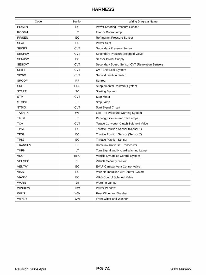
PS/SEN EC Power Steering Pressure Sensor
ROOM/L LT Interior Room Lamp
RP/SEN EC Refrigerant Pressure Sensor
SEAT SE Power Seat
SECPS CVT Secondary Pressure Sensor
SECPSV CVT Secondary Pressure Solenoid Valve
SEN/PW EC Sensor Power Supply
SESCVT CVT Secondary Speed Sensor CVT (Revolution Sensor)
SHIFT CVT CVT Shift Lock System
SPSW CVT Second position Switch
SROOF RF Sunroof
SRS SRS Supplemental Restraint System
START SC Starting System
STM CVT Step Motor
STOP/L LT Stop Lamp
STSIG CVT Start Signal Circuit
T/WARN WT Low Tire Pressure Warning System
TAIL/L LT Parking, License and Tail Lamps
TCV CVT Torque Converter Clutch Solenoid Valve
TPS1 EC Throttle Position Sensor (Sensor 1)
TPS2 EC Throttle Position Sensor (Sensor 2)
TPS3 EC Throttle Position Sensor
TRANSCV BL Homelink Universal Transceiver
TURN LT Turn Signal and Hazard Warning Lamp
VDC BRC Vehicle Dynamics Control System
VEHSEC BL Vehicle Security System
VENT/V EC EVAP Canister Vent Control Valve
VIAS EC Variable Induction Air Control System
VIAS/V EC VIAS Control Solenoid Valve
WARN DI Warning Lamps
WINDOW GW Power Window
WIP/R WW Rear Wiper and Washer
WIPER WW Front Wiper and Washer
Code Section Wiring Diagram Name
ELECTRICAL UNITS LOCATION
PG-75
C
D
E
F
G
H
I
J
L
M
A
B
PG
Revision; 2004 April 2003 Murano
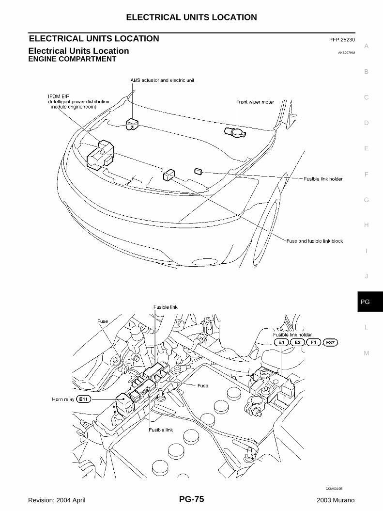
ELECTRICAL UNITS LOCATION PFP:25230
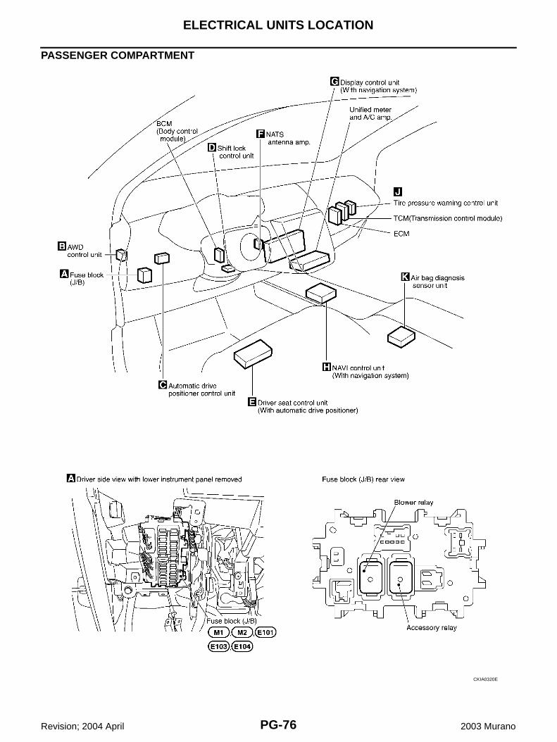
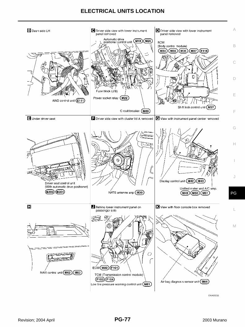
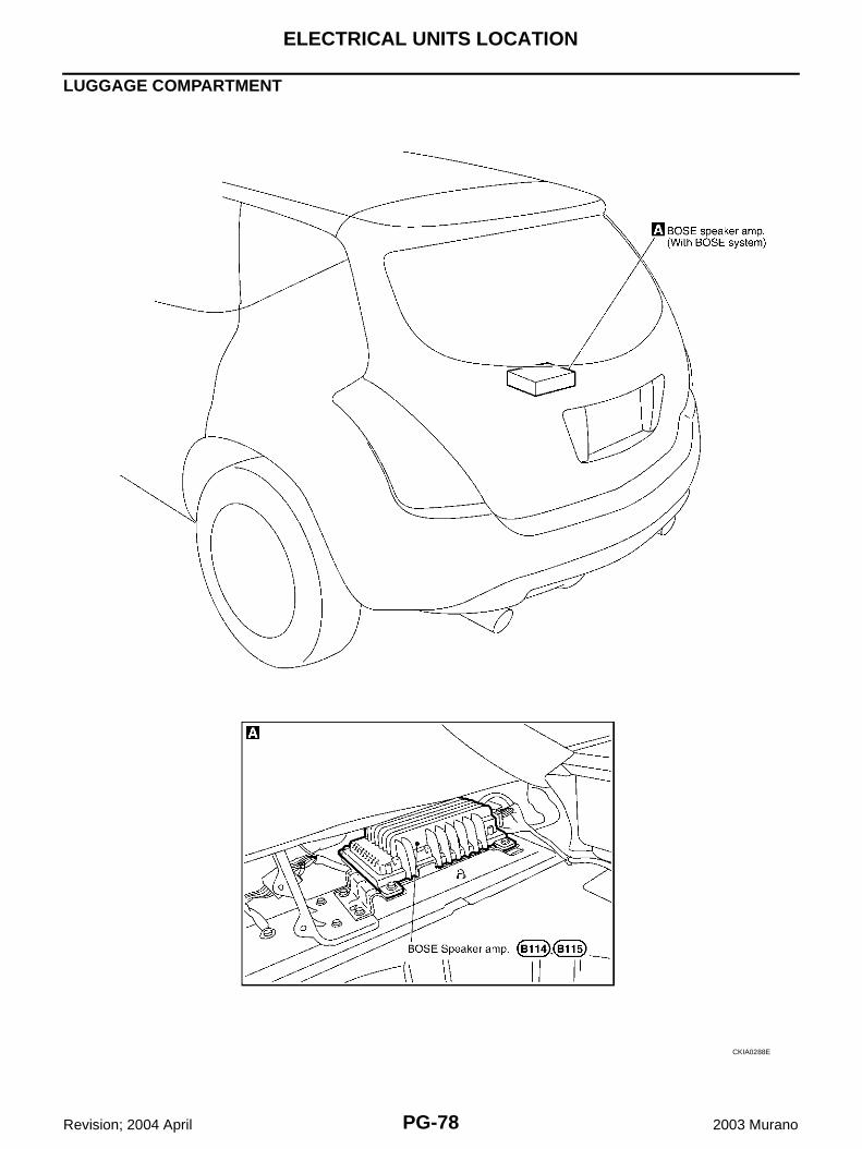
Electrical Units Location AKS007HM
ENGINE COMPARTMENT
CKIA0319E
PG-76
ELECTRICAL UNITS LOCATION
Revision; 2004 April 2003 Murano
PASSENGER COMPARTMENT
CKIA0320E
ELECTRICAL UNITS LOCATION
PG-77
C
D
E
F
G
H
I
J
L
M
A
B
PG
Revision; 2004 April 2003 Murano
CKIA0321E
PG-78
ELECTRICAL UNITS LOCATION
Revision; 2004 April 2003 Murano
LUGGAGE COMPARTMENT
CKIA0288E
HARNESS CONNECTOR
PG-79
C
D
E
F
G
H
I
J
L
M
A
B
PG
Revision; 2004 April 2003 Murano
HARNESS CONNECTOR PFP:00011
Description AKS007HN
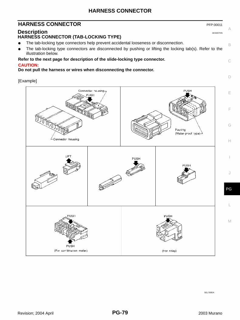
HARNESS CONNECTOR (TAB-LOCKING TYPE)● The tab-locking type connectors help prevent accidental looseness or disconnection.● The tab-locking type connectors are disconnected by pushing or lifting the locking tab(s). Refer to the
illustration below.Refer to the next page for description of the slide-locking type connector.CAUTION:Do not pull the harness or wires when disconnecting the connector.
[Example]
SEL769DA
PG-80
HARNESS CONNECTOR
Revision; 2004 April 2003 Murano
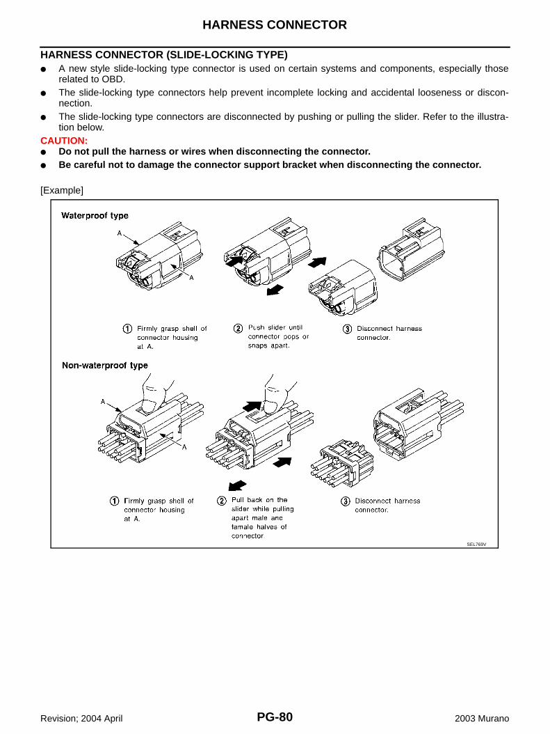
HARNESS CONNECTOR (SLIDE-LOCKING TYPE)● A new style slide-locking type connector is used on certain systems and components, especially those
related to OBD.● The slide-locking type connectors help prevent incomplete locking and accidental looseness or discon-
nection.● The slide-locking type connectors are disconnected by pushing or pulling the slider. Refer to the illustra-
tion below.CAUTION:● Do not pull the harness or wires when disconnecting the connector.● Be careful not to damage the connector support bracket when disconnecting the connector.
[Example]
SEL769V
JOINT CONNECTOR (J/C)
PG-81
C
D
E
F
G
H
I
J
L
M
A
B
PG
Revision; 2004 April 2003 Murano
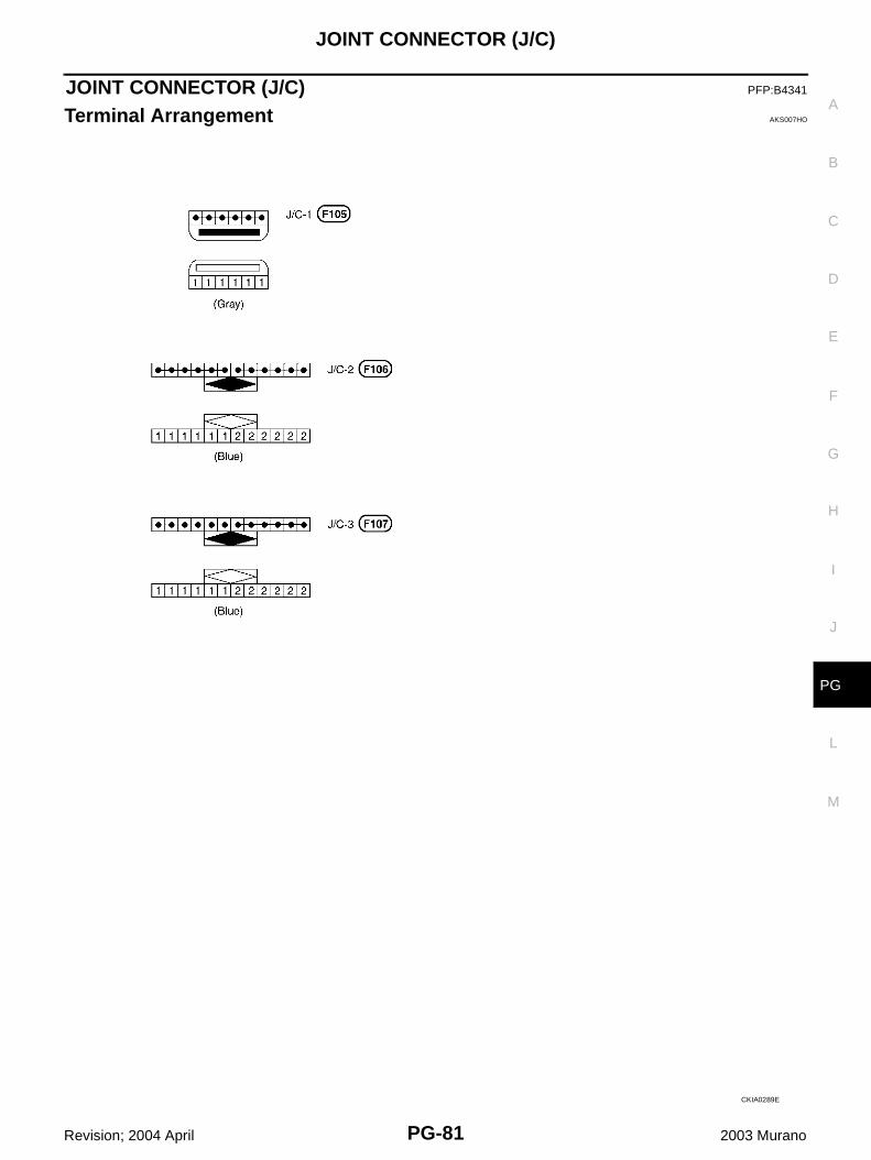
JOINT CONNECTOR (J/C) PFP:B4341
Terminal Arrangement AKS007HO
CKIA0289E
PG-82
ELECTRICAL UNITS
Revision; 2004 April 2003 Murano
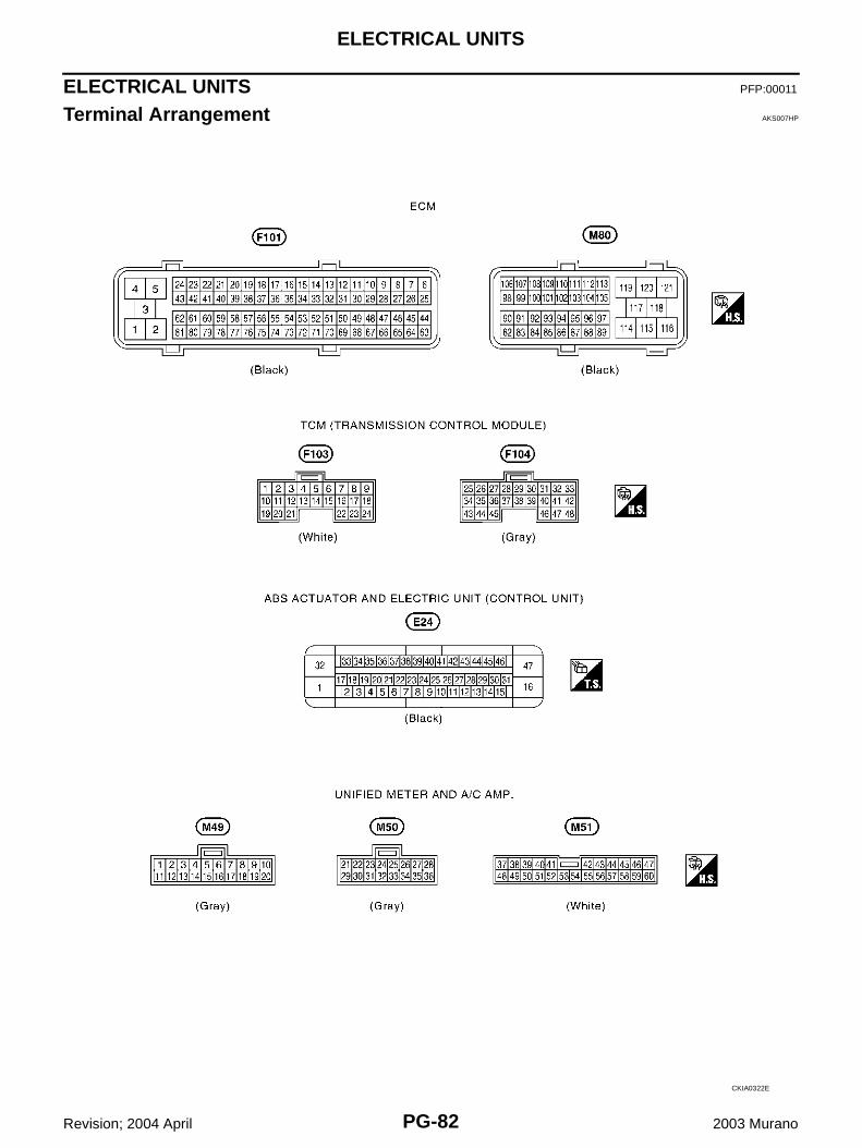
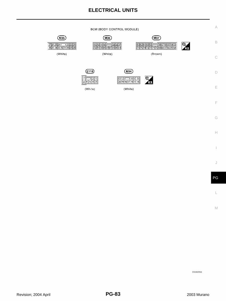
ELECTRICAL UNITS PFP:00011
Terminal Arrangement AKS007HP
CKIA0322E
ELECTRICAL UNITS
PG-83
C
D
E
F
G
H
I
J
L
M
A
B
PG
Revision; 2004 April 2003 Murano
CKIA0291E
PG-84
SMJ (SUPER MULTIPLE JUNCTION)
Revision; 2004 April 2003 Murano
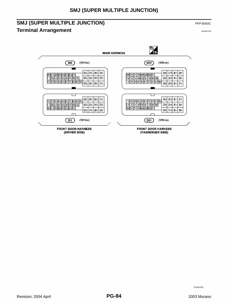
SMJ (SUPER MULTIPLE JUNCTION) PFP:B4341
Terminal Arrangement AKS007HQ
CKIA0292E
STANDARDIZED RELAY
PG-85
C
D
E
F
G
H
I
J
L
M
A
B
PG
Revision; 2004 April 2003 Murano
STANDARDIZED RELAY PFP:00011
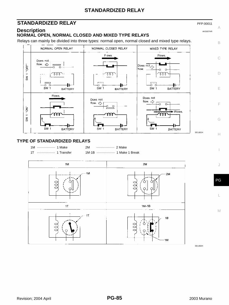
Description AKS007HR
NORMAL OPEN, NORMAL CLOSED AND MIXED TYPE RELAYSRelays can mainly be divided into three types: normal open, normal closed and mixed type relays.
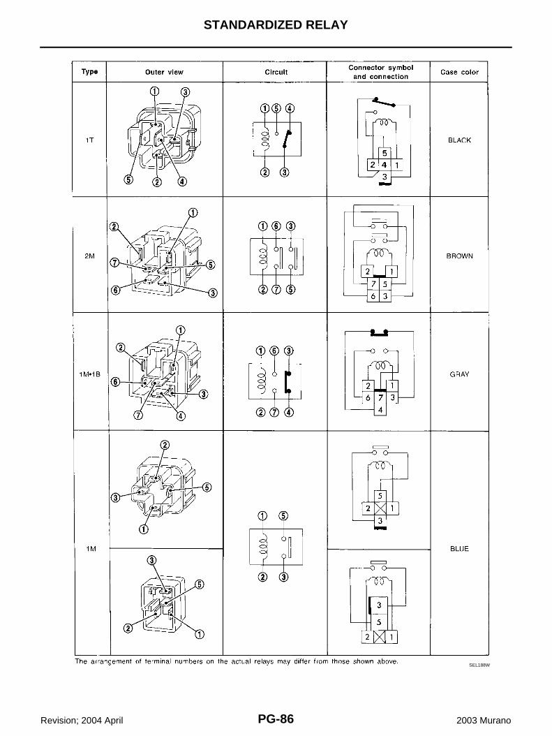
TYPE OF STANDARDIZED RELAYS
SEL881H
1M ···················· 1 Make 2M ···················· 2 Make
1T ···················· 1 Transfer 1M·1B ···················· 1 Make 1 Break
SEL882H
PG-86
STANDARDIZED RELAY
Revision; 2004 April 2003 Murano
SEL188W
FUSE BLOCK - JUNCTION BOX (J/B)
PG-87
C
D
E
F
G
H
I
J
L
M
A
B
PG
Revision; 2004 April 2003 Murano
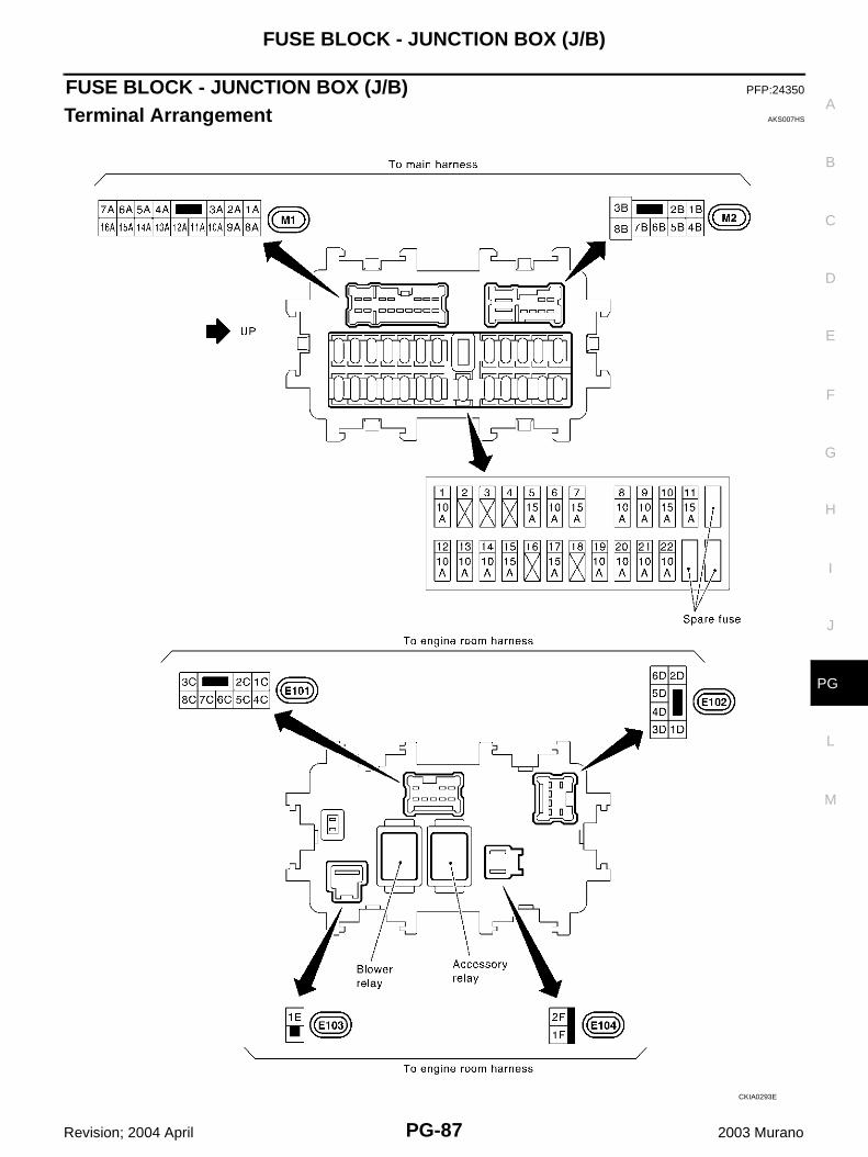
FUSE BLOCK - JUNCTION BOX (J/B) PFP:24350
Terminal Arrangement AKS007HS
CKIA0293E
PG-88
FUSE, FUSIBLE LINK AND RELAY BOX
Revision; 2004 April 2003 Murano
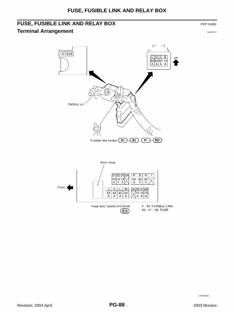
FUSE, FUSIBLE LINK AND RELAY BOX PFP:24382
Terminal Arrangement AKS007HT
CKIA0323E