Embed Size (px)
Citation preview
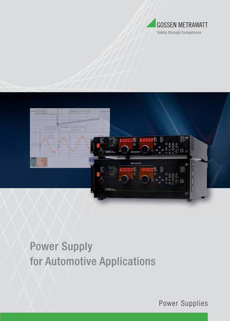
Power Supply for Automotive Applications
Power Suppl ies
2
Kevork-Deniz VartanogluDipl.-Ing. (FH)Product Manager, Power Supply DivisionPhone: +49 911 8602-717Fax: +49 911 8602-80717Mobile phone: +49 171 [email protected]
Contents
1 Use of Test Signals in the Automotive Field .........................................................................................................3
2 Standards and Transient Pulses (ISO 7637) within the Automotive Electrical System .........................................3
3 Important Test Categories for Automotive Test Setups .........................................................................................7
4 Requirements for Laboratory Power Supplies (e.g. SYSKON KONSTANTER) ........................................................7
5 The New KONSTANTER Generation: SYSKON P Series .........................................................................................9
6 Product Overview: SYSKON P Series Computer Controlled Laboratory Power Supplies ....................................11
3
High Performance Laboratory Power Supplies Generate Test Signals (ISO 7637) in the Field of Automotive Electrical Engineering
1 Use of Test Signals in the Automotive Field
In the face of international competition, the automobile industry is becoming more and more interested in implementing economically feasible, ideal solutions in the vehicle manufacturing process. Highly complex requirements are common in modern automotive technology. In order to incorporate these demanding functions into passenger vehicles and trucks, electrical and electronic components and modules must be subjected to a broad range of tests and analyses during the R&D and production phases. These evaluations and the resulting information are important, in order to be able to make well founded decisions regarding quality standards and readiness for series production. And it must always be assured that the greatest majority of the tests are executed under realistic conditions of use, thus making it possible to guarantee error-free, safe functioning in advance.
As far as test conditions are concerned, this means that the environment in which testing takes place, the test signal and the test procedure must meet the demands of highly variable operating states, in order to simulate the various conditions in the vehicle as perfectly as possible.
In the fi eld of automobile manufacturing, motor controlled and electronically regulated devices include, amongst others, complex airbags, ABS, headlight technology and complete operating units in the center console, as well as electronically regulated components in doors, windows and in the roof. This great multiplicity of functional assemblies must be tested as reliably and safely as possible, and guaranteed for subse-quent use in series production.
In order to assure that different impedances within the vehicle’s electrical system do not cause any problems for subsequent series produc-tion, vehicle-specifi c test signals and modifi cations of standard test pulses have to be developed.
2 Standards and Transient Pulses (ISO 7637) within the Automotive Electrical System
Test signals are specifi ed in the SAE standards (Society of Automotive Engineers), which cover distinctive functions and conditions of use. In addition to these, test signals are also specifi ed by the manufacturers.
Transient pulses within the automotive electrical system are caused when loads or inductances are switched. They’re described in ISO 7637 (pulses) for the purpose of testing for interference immunity.
Depending upon how the device under test has been wired into the electrical system, it may be impaired by various pulses. The ISO standard differentiates amongst fi ve different types of pulses (E1 through E5, see fi gures 1 through 5), which demonstrate varying amplitudes and durations depending upon how they are caused..
4
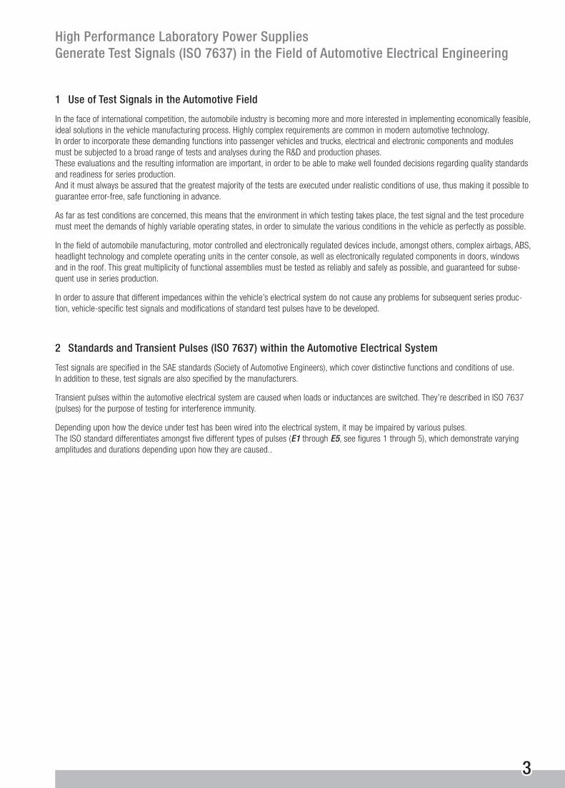
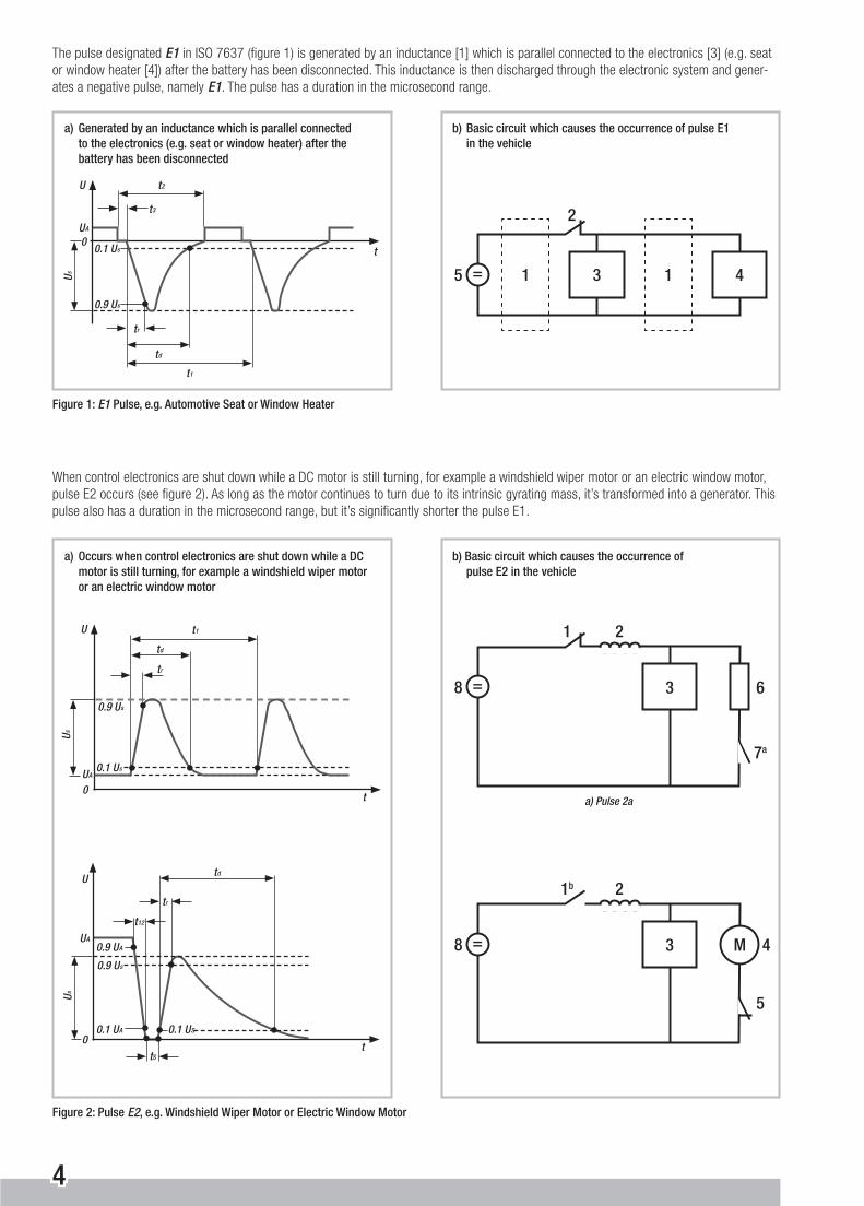
When control electronics are shut down while a DC motor is still turning, for example a windshield wiper motor or an electric window motor, pulse E2 occurs (see fi gure 2). As long as the motor continues to turn due to its intrinsic gyrating mass, it’s transformed into a generator. This pulse also has a duration in the microsecond range, but it’s signifi cantly shorter the pulse E1.
U s
t
U
00.1 U s
0.9 U s
t 1
t d
t r
t 2
t 3
U A
a) Generated by an inductance which is parallel connected to the electronics (e.g. seat or window heater) after the battery has been disconnected
5 = 1 13 4
2
b) Basic circuit which causes the occurrence of pulse E1 in the vehicle
Figure 1: E1 Pulse, e.g. Automotive Seat or Window Heater
The pulse designated E1 in ISO 7637 (fi gure 1) is generated by an inductance [1] which is parallel connected to the electronics [3] (e.g. seat or window heater [4]) after the battery has been disconnected. This inductance is then discharged through the electronic system and gener-ates a negative pulse, namely E1. The pulse has a duration in the microsecond range.
Figure 2: Pulse E2, e.g. Windshield Wiper Motor or Electric Window Motor
a) Occurs when control electronics are shut down while a DC motor is still turning, for example a windshield wiper motor or an electric window motor
b) Basic circuit which causes the occurrence of pulse E2 in the vehicle
U s
t
U
0
0.1 U s
0.9 U s
t 1
t d
t r
U A
8 =
7a
1
3 6
2
a) Pulse 2a
8 =
5
1b
3 4
2
M
t 12
U s
t
U
00.1 U A
0.9 U s
t d
t r
U A0.9 U A
0.1 U S
tS
5
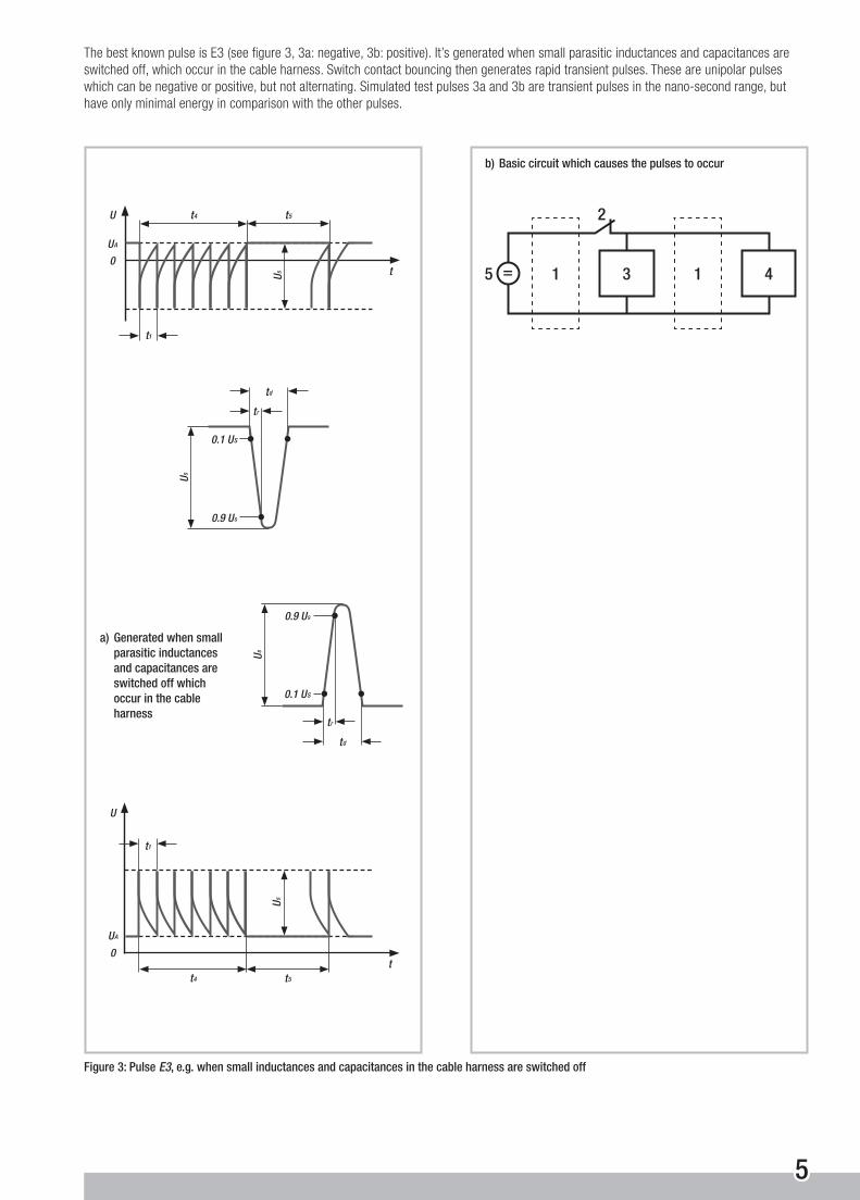
The best known pulse is E3 (see fi gure 3, 3a: negative, 3b: positive). It’s generated when small parasitic inductances and capacitances are switched off, which occur in the cable harness. Switch contact bouncing then generates rapid transient pulses. These are unipolar pulses which can be negative or positive, but not alternating. Simulated test pulses 3a and 3b are transient pulses in the nano-second range, but have only minimal energy in comparison with the other pulses.
a) Generated when small parasitic inductances and capacitances are switched off which occur in the cable harness
b) Basic circuit which causes the pulses to occur
Figure 3: Pulse E3, e.g. when small inductances and capacitances in the cable harness are switched off
5 = 1 13 4
2
U s t
U
0
t 5t 4
U A
t1
U s
t
U
0
t 5t 4
U A
t1
t d
U s
0.9 U s
t r
0.1 U S
t d
U s
0.9 U s
t r
0.1 U S
6
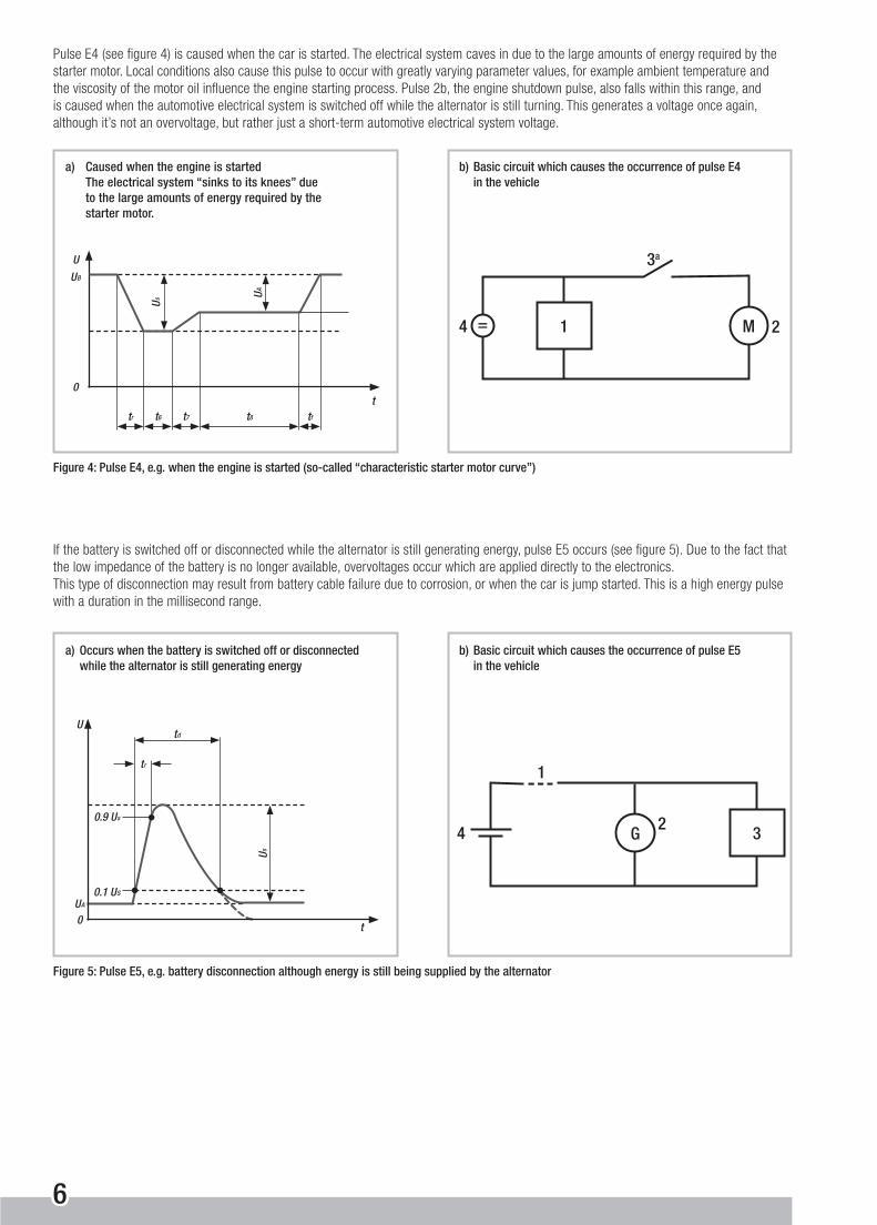
Pulse E4 (see fi gure 4) is caused when the car is started. The electrical system caves in due to the large amounts of energy required by the starter motor. Local conditions also cause this pulse to occur with greatly varying parameter values, for example ambient temperature and the viscosity of the motor oil infl uence the engine starting process. Pulse 2b, the engine shutdown pulse, also falls within this range, and is caused when the automotive electrical system is switched off while the alternator is still turning. This generates a voltage once again, although it’s not an overvoltage, but rather just a short-term automotive electrical system voltage.
a) Caused when the engine is started The electrical system “sinks to its knees” due to the large amounts of energy required by the starter motor.
b) Basic circuit which causes the occurrence of pulse E4 in the vehicle
Figure 4: Pulse E4, e.g. when the engine is started (so-called “characteristic starter motor curve”)
Figure 5: Pulse E5, e.g. battery disconnection although energy is still being supplied by the alternator
a) Occurs when the battery is switched off or disconnected while the alternator is still generating energy
b) Basic circuit which causes the occurrence of pulse E5 in the vehicle
If the battery is switched off or disconnected while the alternator is still generating energy, pulse E5 occurs (see fi gure 5). Due to the fact that the low impedance of the battery is no longer available, overvoltages occur which are applied directly to the electronics. This type of disconnection may result from battery cable failure due to corrosion, or when the car is jump started. This is a high energy pulse with a duration in the millisecond range.
4 = 1
3a
M 2
4
1
32G
U s
t
U
0
0.9 U s
t d
t r
U A0.1 U S
tr
U
0
U B
t6 t7 tft8
t
U s
U A

7
3 Important Test Categories for Automotive Test Setups
Impulses E1 through E5 impressively demonstrate which categories of tests are executed in, amongst other areas, the automotive fi eld, and which have to be implemented by means of laboratory power supplies in the testing, R&D and production phases.
Three categories of test setups have been established for metrological ascertainment of various pulses:
■ Tests with high frequency test signals with edge rises in the µs range
■ Tests in the medium dynamic range for which edge rises in the ms range are required
■ Tests in a semi-static operating state in accordance with battery voltage tolerances
Fast, high-frequency pulses (down into the µs range) are measured with the help of a special mechanical switch, a simulated automotive elec-trical system and an oscilloscope. The test setup is precisely described in ISO 7637, and must be strictly adhered to because results are not otherwise reproducible,
The mean or static pulses (down into the ms range) are ascertained in a similar fashion with an electronic switch, a simulated automotive electrical system and an oscilloscope. It’s precisely in this working range that the new power supply from GMC-I Messtechnik is setting new standards, which fulfi lls nearly all requirements specifi ed by the automotive industry with SYSKON P series KONSTANTERs.
4 Requirements for Laboratory Power Supplies (e.g. SYSKON KONSTANTER)
All of the pulses and signals shown here (E1 through E5) lie within the medium dynamic range, which means that response times in the ms range are required (E1 and E2 in the µs range, E3 in the ns range). These times make reference to setpoint changes in both directions, from lower to higher values and vice versa. In order to achieve these times with power supplies, a number of special features and challenges must be accommodated by the device design, because, amongst other reasons, the consumer to be supplied with power must be seen as a part of the controlled system which directly infl uences dynamic performance.
Modern laboratory power supplies are equipped with switching controller technology, in order to achieve greater levels of effi ciency in weight and size reduction. However, switching controllers require an appropriate fi lter with an output capacitor in the output circuit. The capaci-tor, whose rating may be several thousand µF depending upon power, directly determines dynamic performance. In addition to load current, adequately high charging current must be permissible in order to achieve short response times from lower to higher output voltages. Accord-ingly, this charging current infl uences dimensioning of the power component, right on up to the power connection.
Rapid discharging must be assured for the other direction, namely reducing output voltage. Due to the fact that we cannot always assume that adequately high load current will be available, discharging must be accomplished by the power supply itself. An accelerated discharging function can be achieved by means of an integrated dynamic load or current sink. This concept is used for the SYSKON P series.
Another possibility is to rapidly discharge the output capacitor by returning its energy to the intermediate circuit at the primary side via the power transformer. This concept prevents any further power loss within the overall system, and is made use of in all high precision KON-STANTERs (e.g. SLP and SSP series KONSTANTERs as well) from GMC-I Messtechnik under the name of BET technology (bidirectional energy transport).
In either case, infl uence on the thermal balance of the entire power component must be observed. Beyond this, additional functions must also be observed and taken into consideration in the layout and dimensioning of the controller. The overall control loop is thus expanded to include an additional function.
In addition to considerations within the power component and the control loop, the power supply’s internal data memory module (setup and sequence memory) and its user interface must also be laid our appropriately for the generation of signals of this type. It must be possible to save the intermediate points required for simulating the signals in adequate numbers to the power supply itself, in order to allow for signal generation without the use of a computer (remote). A memory module with suffi cient capacity is required to this end. This memory module is subdivided into a smaller range (setup memory) to which complete device confi gurations can be stored, and a larger range for saving the sequences (sequence memory).

8
Important parameters can be saved to the smaller confi guration memory, which are necessary for specifi c applications. The confi guration required for a given application can thus be quickly and easily recalled.
The larger memory location is used to save parameters for voltage and current profi les – so-called sequences. The power supply is thus capable of running and reading out stored sequences autonomously, independent of chronological data traffi c sequences with the controlling computer, and frees up the computer for other tasks at the same time.
Depending upon the scope of the sequences stored to the SYSKON KONSTANTER, several profi les can be saved and defi ned by means of the start and stop address. This allows for fl exible adaptation to various applications. In order to represent test pulses of this sort as a sequence, four parameters are required for each intermediate point in the memory location (sequence number, no.) (see fi gure 11, “View and Edit” window):
■ Voltage value (Uset in V)
■ Current value (Iset in A)
■ Dwell time (Tset in s)
■ Function parameter (Fset)
In connection with the load, the entry of voltage and current values allows for free determination as to whether or not voltage or current injection should take place for the power consumer at this point. The dwell time to be entered per intermediate point determines how long the respective value will be read out when the sequence is run, as well as the duration of the overall sequence Minimum dwell time amounts to 1 ms.
The start and stop addresses are also required when defi ning a sequence, which represent the fi rst and last memory locations of the respec-tive sequence. The number of repetitions must also be specifi ed, which indicates how many times the sequence will be read out, as well as information specifying the status of the power output after the sequence has been completed. The output can be left at the last value speci-fi ed in the sequence, or it can be switched off.
The function parameter can be used to determine, amongst other factors, output shutdown. If the CLR (clear) function parameter is included in the last memory location of a given sequence, this location is skipped when the sequence is repeated. However, the output is switched off after completion of the last repetition, for example in order to connect the next device under test.
If several devices are required in a single system, it may be necessary to synchronize the time sequences with one another. This is accomplished with the help of a hardware trigger input. With the SYSKON KONSTANTER, a sequence can be started manually (menu key on the instrument), or by means of a computer (via USB port) or a trigger signal (analog port, ANIF).
9
5 The New KONSTANTER Generation: SYSKON P Series
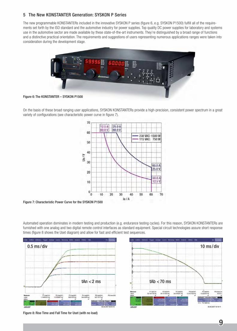
The new programmable KONSTANTERs included in the innovative SYSKON P series (fi gure 6, e.g. SYSKON P1500) fulfi ll all of the require-ments set forth by the ISO standard and the automotive industry for power supplies. Top quality DC power supplies for laboratory and systems use in the automotive sector are made available by these state-of-the-art instruments. They’re distinguished by a broad range of functions and a distinctive practical orientation. The requirements and suggestions of users representing numerous applications ranges were taken into consideration during the development stage.
On the basis of these broad ranging user applications, SYSKON KONSTANTERs provide a high-precision, consistent power spectrum in a great variety of confi gurations (see characteristic power curve in fi gure 7).
Automated operation dominates in modern testing and production (e.g. endurance testing cycles). For this reason, SYSKON KONSTANTERs are furnished with one analog and two digital remote control interfaces as standard equipment. Special circuit technologies assure short response times (fi gure 8 shows the Uset diagram) and allow for fast and effi cient test sequences.
Figure 8: Rise Time and Fall Time for Uset (with no load)
Figure 6: The KONSTANTER – SYSKON P1500
Figure 7: Characteristic Power Curve for the SYSKON P1500
tAb < 70 mstAn < 2 ms
0.5 ms / div 10 ms / div

10
The SYSKON KONSTANTER includes convenient software as a standard feature for quick and easy operation of computer-controlled systems. Its central element is the soft front-panel (SFP, see fi gure 9).
The software detects KONSTANTERs which are connected to the various possible interfaces including USB, RS 232 and GPIB. Detected KONSTANTERs are identifi ed automatically, and can be selected for use. If several KONSTANTERs have been connected, the software can be started several times, i.e. once for each instrument. In this way, each instrument can be controlled with its own SFP window along with the others.
Figure 9: Soft Front-Panel (SFP) at the SYSKON P1500
It allows the user to take targeted advantage of the comprehensive spectrum of functions offered by the devices in his own application – without any programming at all. The panel is laid out in a clear-cut fashion, and is subdivided into task-specifi c windows (fi gures 10 through 13, selected window excerpts only).
Figure 10: “Basic” Window Figure 11: “View and Edit” Window Including Parameters Information
Figure 12: “Sequence” Window with “Index” Display Figure 13: “Sequence” Window with “Time” Display
11
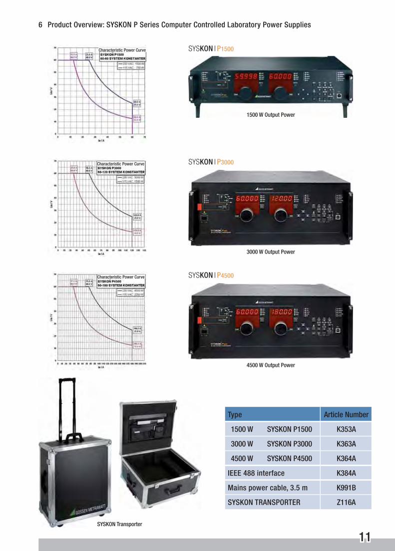
6 Product Overview: SYSKON P Series Computer Controlled Laboratory Power Supplies
Type Article Number
1500 W SYSKON P1500 K353A
3000 W SYSKON P3000 K363A
4500 W SYSKON P4500 K364A
IEEE 488 interface K384A
Mains power cable, 3.5 m K991B
SYSKON TRANSPORTER Z116A
SYSKON l P3000
SYSKON l P4500
SYSKON l P1500
SYSKON Transporter
1500 W Output Power
3000 W Output Power
4500 W Output Power
Characteristic Power Curve
Characteristic Power Curve
Characteristic Power Curve
GMC-I Messtechnik GmbHSüdwestpark 1590449 Nürnberg, GermanyPhone: +49 911 8602-111Fax: +49 911 8602-777e-mail: [email protected]
Printed in Germany • Subject to change without notice • 1/1.10 • 3-337-242-03