Embed Size (px)
Citation preview
Mech
atron
ica
KOMBIS TMM8003
Installation
Electrical Systems
Mech
atron
ica
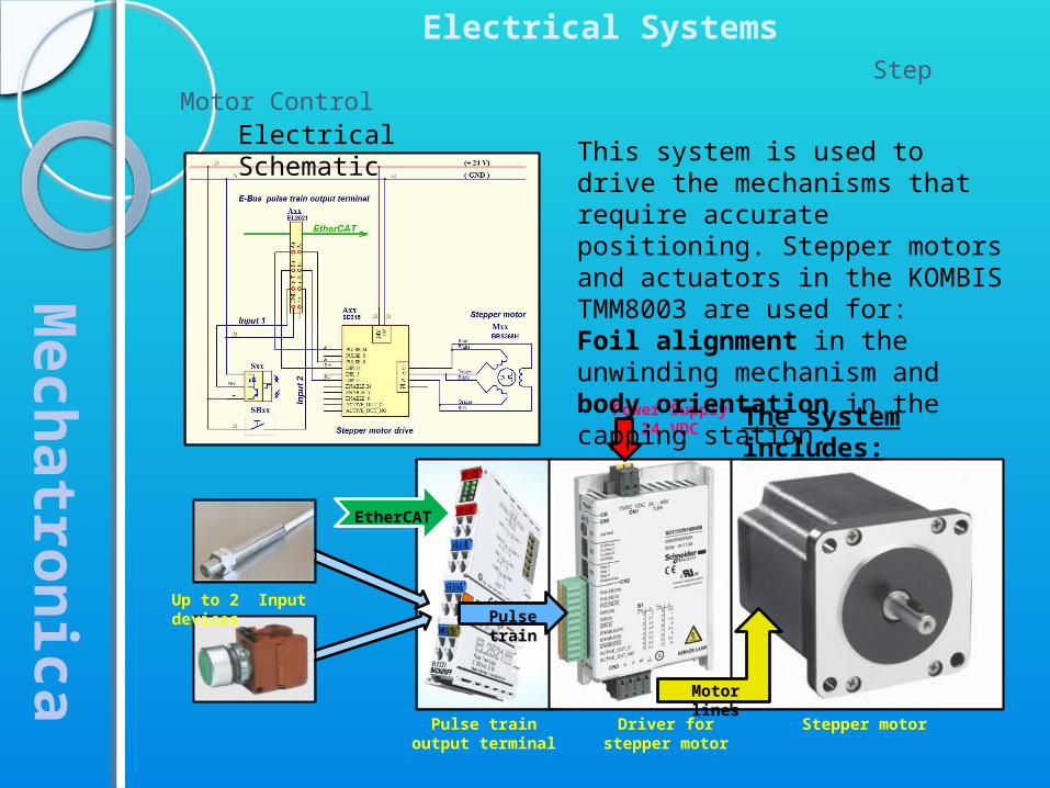
Electrical Systems Step Motor Control
Power Supply24 VDC
Pulse train
Motor lines
EtherCAT
Electrical Schematic
Up to 2 Input devices
This system is used to drive the mechanisms that require accurate positioning. Stepper motors and actuators in the KOMBIS TMM8003 are used for:Foil alignment in the unwinding mechanism and body orientation in the capping station.
The system includes:
Pulse train output terminal
Driver for stepper motor
Stepper motor
Mech
atron
ica
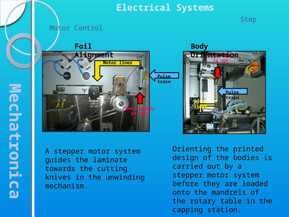
Electrical Systems Step Motor Control
Power Supply24 VDC
Power Supply24 VDC
Pulse train
Pulse train
Motor lines
Motor lines
Foil Alignment Body Orientation
A stepper motor system guides the laminate towards the cutting knives in the unwinding mechanism.
Orienting the printed design of the bodies is carried out by a stepper motor system before they are loaded onto the mandrels of the rotary table in the capping station.
Mech
atron
ica
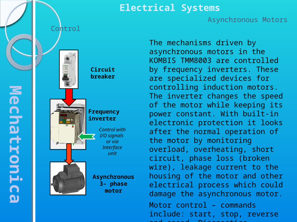
Electrical Systems Asynchronous Motors Control
Circuit breaker
Frequency inverter
Control with I/O signals
or via Interface unit
Asynchronous 3- phase motor
The mechanisms driven by asynchronous motors in the KOMBIS TMM8003 are controlled by frequency inverters. These are specialized devices for controlling induction motors. The inverter changes the speed of the motor while keeping its power constant. With built-in electronic protection it looks after the normal operation of the motor by monitoring overload, overheating, short circuit, phase loss (broken wire), leakage current to the housing of the motor and other electrical process which could damage the asynchronous motor.
Motor control – commands include: start, stop, reverse and speed. Diagnostics including inverter status, alarms, etc. are carried out through I/O signals sent between the main controller and the inverter.
Mech
atron
ica
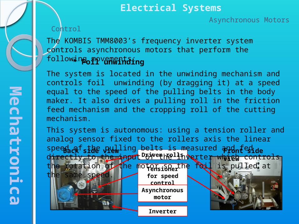
Front side viewBack side view
Electrical Systems Asynchronous Motors Control
Tensioner for speed control
Inverter
Driven rolls
Asynchronous motor
The KOMBIS TMM8003’s frequency inverter system controls asynchronous motors that perform the following movements:
* Foil unwinding
The system is located in the unwinding mechanism and controls foil unwinding (by dragging it) at a speed equal to the speed of the pulling belts in the body maker. It also drives a pulling roll in the friction feed mechanism and the cropping roll of the cutting mechanism.
This system is autonomous: using a tension roller and analog sensor fixed to the rollers axis the linear speed of the pulling belts is measured and fed directly to the input of the inverter which controls the rotation of the motor so the foil is pulled at the same speed.
Mech
atron
ica
Asynchronous motor
Gear box
Pulling belts
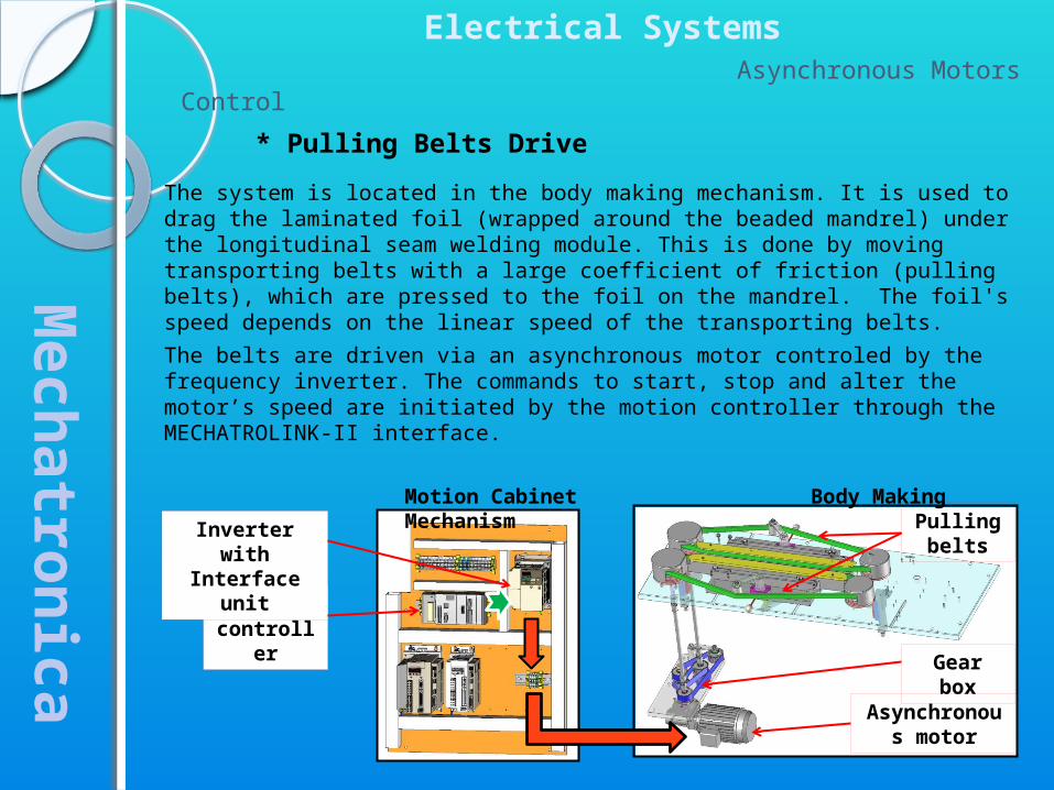
* Pulling Belts Drive
The system is located in the body making mechanism. It is used to drag the laminated foil (wrapped around the beaded mandrel) under the longitudinal seam welding module. This is done by moving transporting belts with a large coefficient of friction (pulling belts), which are pressed to the foil on the mandrel. The foil's speed depends on the linear speed of the transporting belts.
The belts are driven via an asynchronous motor controled by the frequency inverter. The commands to start, stop and alter the motor’s speed are initiated by the motion controller through the MECHATROLINK-II interface.
Electrical Systems Asynchronous Motors Control
Motion controller
Inverter with Interface unit
Motion Cabinet Body Making Mechanism
Mech
atron
ica
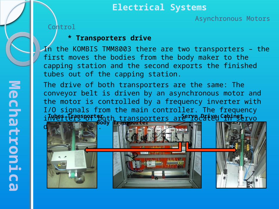
* Transporters drive
Electrical Systems Asynchronous Motors Control
In the KOMBIS TMM8003 there are two transporters – the first moves the bodies from the body maker to the capping station and the second exports the finished tubes out of the capping station.
The drive of both transporters are the same: The conveyor belt is driven by an asynchronous motor and the motor is controlled by a frequency inverter with I/O signals from the main controller. The frequency inverters of both transporters are located in servo drive cabinet.
Tubes Transporter Servo Drive Cabinet Body Transporter
Mech
atron
ica
Electrical Systems Servo Motors Control
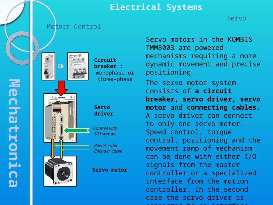
ORCircuit breaker :
monophase or three-phase
Servo driver
Control with I/O signals
Servo motor
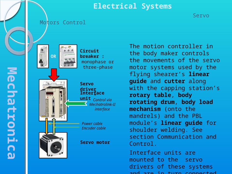
Servo motors in the KOMBIS TMM8003 are powered mechanisms requiring a more dynamic movement and precise positioning.
The servo motor system consists of a circuit breaker, servo driver, servo motor and connecting cables. A servo driver can connect to only one servo motor. Speed control , torque control, positioning and the movement ramp of mechanism can be done with either I/O signals from the master controller or a specialized interface from the motion controller. In the second case the servo driver is connected to an interface unit playing the part of "translator" between the motion controller and the servo driver.
Power cable Encoder cable
Mech
atron
ica
Electrical Systems Servo Motors Control
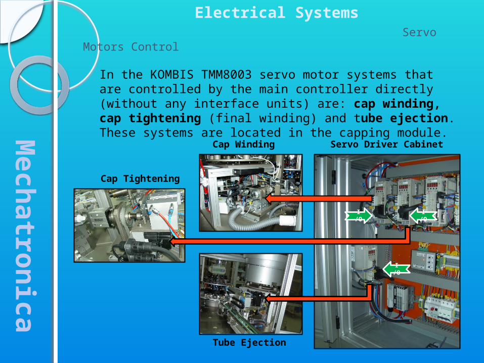
In the KOMBIS TMM8003 servo motor systems that are controlled by the main controller directly (without any interface units) are: cap winding, cap tightening (final winding) and tube ejection. These systems are located in the capping module.
Cap Winding
Tube Ejection
Cap Tightening
Servo Driver Cabinet
O/I
O/I
O/I
Mech
atron
ica
Electrical Systems Servo Motors Control
OR
Power cable Encoder cable
Control via Mechatrolink-II
interface
Circuit breaker :monophase or three-phase
Servo driver+
Servo motor
Interface unit
The motion controller in the body maker controls the movements of the servo motor systems used by the flying shearer’s linear guide and cutter along with the capping station’s rotary table, body rotating drum, body load mechanism (onto the mandrels) and the PBL module’s linear guide for shoulder welding. See section Communication and Control.
Interface units are mounted to the servo drivers of these systems and are in turn connected by control cables to the MECHATROLINK-II interface of the motion controller.
Mech
atron
ica
Electrical Systems Vibro-Hoppers Control
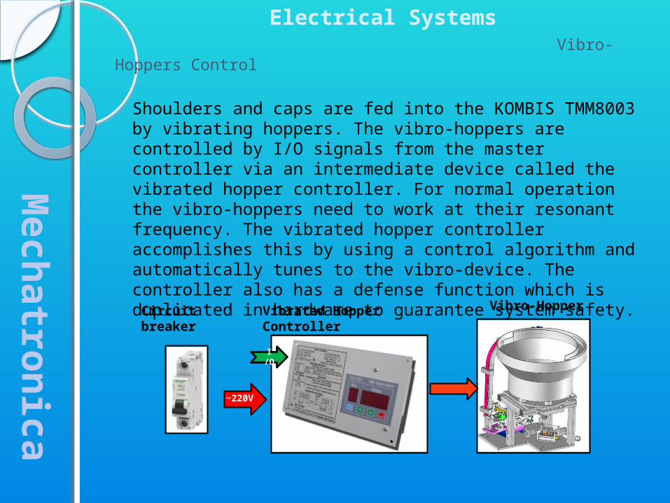
Shoulders and caps are fed into the KOMBIS TMM8003 by vibrating hoppers. The vibro-hoppers are controlled by I/O signals from the master controller via an intermediate device called the vibrated hopper controller. For normal operation the vibro-hoppers need to work at their resonant frequency. The vibrated hopper controller accomplishes this by using a control algorithm and automatically tunes to the vibro-device. The controller also has a defense function which is duplicated in hardware to guarantee system safety.
O/I
Circuit breaker Vibrated Hopper Controller Vibro-Hopper
~220V
Mech
atron
ica
Electrical Systems Hot Air Control
Work air flow
Min. air flow Flowmeter
Hot Air device
Electronic Relays
Thermo sensor
Control Relays
feedback
temperature
Temperature Regulator
Circuit breaker
three-phase
3 x ~ 400 V
Flow Regulators
~ 250 V
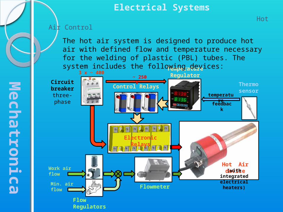
The hot air system is designed to produce hot air with defined flow and temperature necessary for the welding of plastic (PBL) tubes. The system includes the following devices:
(with integrated electrical heaters)
Mech
atron
ica
Electrical Systems Hot Air Control
Welding Module
Control Panel
Air Distributer
PBL-1 Module
Body Maker
Capping Station
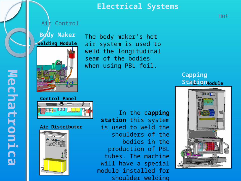
The body maker’s hot air system is used to weld the longitudinal seam of the bodies when using PBL foil.
In the capping station this system is used to weld
the shoulders of the bodies in the production of PBL tubes.
The machine will have a special module installed for
shoulder welding called a “PBL-1 Module”.
Mech
atron
ica
Electrical SystemsTHROUBLE SHOOTING
Problem Cause Remedy
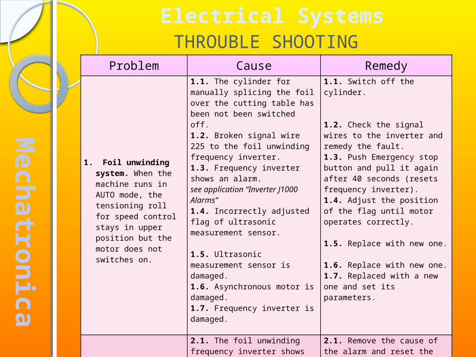
1. Foil unwinding system. When the machine runs in AUTO mode, the tensioning roll for speed control stays in upper position but the motor does not switches on.
1.1. The cylinder for manually splicing the foil over the cutting table has been not been switched off.1.2. Broken signal wire 225 to the foil unwinding frequency inverter.1.3. Frequency inverter shows an alarm. see application “Inverter J1000 Alarms”1.4. Incorrectly adjusted flag of ultrasonic measurement sensor.
1.5. Ultrasonic measurement sensor is damaged.1.6. Asynchronous motor is damaged.1.7. Frequency inverter is damaged.
1.1. Switch off the cylinder.
1.2. Check the signal wires to the inverter and remedy the fault.1.3. Push Emergency stop button and pull it again after 40 seconds (resets frequency inverter). 1.4. Adjust the position of the flag until motor operates correctly.
1.5. Replace with new one.
1.6. Replace with new one.1.7. Replaced with a new one and set its parameters.
2. Foil unwinding system - When the machine runs in AUTO mode, the scrap suction nozzle under the cutting mechanism is not operating.
2.1. The foil unwinding frequency inverter shows an alarm. See the application “Inverter J1000 Alarms”.2.2. The foil unwinding inverter has incorrect parameters set. Parameter L4-01 should have a value of 0.5.2.3. Broken signal wire 1103 from the inverter to Festo's valve terminal in the body maker.2.4. Faulty valve for scrap nozzle in Festo's valve terminal.
2.1. Remove the cause of the alarm and reset the inverter - see p.1.3.
2.2. Set correct parameters. Use the application "Servo Drives and Frequency Inverter Parameters“.2.3. Check the signal circuit and remove the fault. 2.4. Replace with new one.
Mech
atron
ica
Electrical SystemsTHROUBLE SHOOTING
Problem Cause Remedy
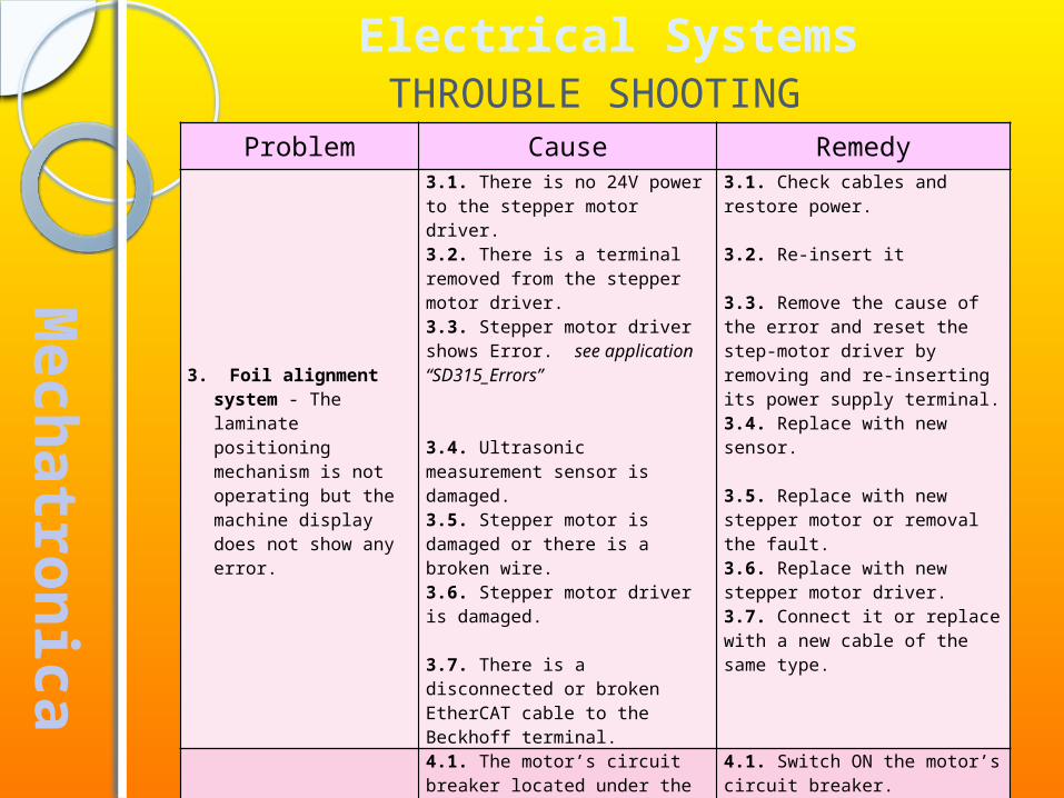
3. Foil alignment system - The laminate positioning mechanism is not operating but the machine display does not show any error.
3.1. There is no 24V power to the stepper motor driver.3.2. There is a terminal removed from the stepper motor driver.3.3. Stepper motor driver shows Error. see application “SD315_Errors”
3.4. Ultrasonic measurement sensor is damaged.3.5. Stepper motor is damaged or there is a broken wire.3.6. Stepper motor driver is damaged.
3.7. There is a disconnected or broken EtherCAT cable to the Beckhoff terminal.
3.1. Check cables and restore power.
3.2. Re-insert it
3.3. Remove the cause of the error and reset the step-motor driver by removing and re-inserting its power supply terminal.3.4. Replace with new sensor.
3.5. Replace with new stepper motor or removal the fault.3.6. Replace with new stepper motor driver.3.7. Connect it or replace with a new cable of the same type.
4. When starting the machine, its display shows AUTO, but there is no movement.
4.1. The motor’s circuit breaker located under the pulling belt’s drive inverter is switched off.4.2. A broken control signal wire for pulling belt’s drive inverter.4.3. Incorrect setting parameters in Pulling belts drive inverter.
4.1. Switch ON the motor’s circuit breaker.
4.2. Check the control signal’s circuits and remove the fault.4.3. Set the correct parameters in the inverter. See application "Servo Drives and Frequency Inverters Parameters”.
Mech
atron
ica
Electrical SystemsTHROUBLE SHOOTING
Problem Cause Remedy
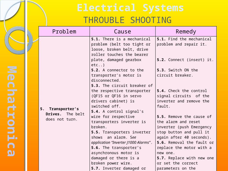
5. Transporter’s Drives. The belt does not turn.
5.1. There is a mechanical problem (belt too tight or loose, broken belt, drive roller touches the bearer plate, damaged gearbox etc..)5.2. A connector to the transporter's motor is disconnected.5.3. The circuit breaker of the respective transporter (QF15 or QF16 in servo drivers cabinet) is switched off.5.4. A control signal's wire for respective transporters inverter is broken.5.5. Transporters inverter shows an alarm. See application “Inverter J1000 Alarms”.5.6. The transporter’s asynchronous motor is damaged or there is a broken power wire.5.7. Inverter damaged or incorrect parameters set.
5.1. Find the mechanical problem and repair it.
5.2. Connect (insert) it.
5.3. Switch ON the circuit breaker.
5.4. Check the control signal circuits of the inverter and remove the fault.
5.5. Remove the cause of the alarm and reset inverter (push Emergency stop button and pull it again after 40 seconds). 5.6. Removal the fault or replace the motor with a new one.5.7. Replace with new one or set the correct parameters on the inverter. See application "Servo Drives and Frequency Inverters Parameters”.
6. Vibrated Hopper not working.
6.1. The circuit breaker QF09 in the servo drivers cabinet is switched off.6.2. Broken or disconnected power cable to the Vibrated Hopper.
6.1. Switch ON the circuit breaker.
6.2. Connect the power cable or remove the fault.
Mech
atron
ica
Electrical SystemsTHROUBLE SHOOTING
Problem Cause Remedy
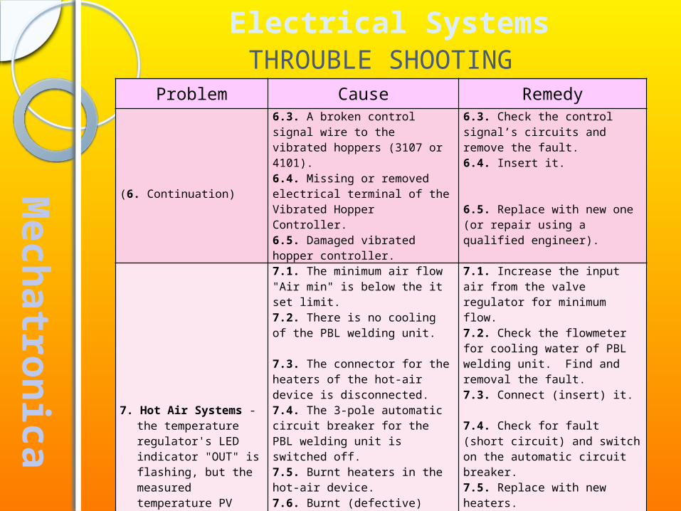
(6. Continuation)
6.3. A broken control signal wire to the vibrated hoppers (3107 or 4101).6.4. Missing or removed electrical terminal of the Vibrated Hopper Controller.6.5. Damaged vibrated hopper controller.
6.3. Check the control signal’s circuits and remove the fault.6.4. Insert it.
6.5. Replace with new one (or repair using a qualified engineer).
7. Hot Air Systems - the temperature regulator's LED indicator "OUT" is flashing, but the measured temperature PV does not change.
7.1. The minimum air flow "Air min" is below the it set limit. 7.2. There is no cooling of the PBL welding unit.
7.3. The connector for the heaters of the hot-air device is disconnected.7.4. The 3-pole automatic circuit breaker for the PBL welding unit is switched off.7.5. Burnt heaters in the hot-air device.7.6. Burnt (defective) electronic relays in the control panel for the hot air system.7.7. A broken wire in the hot-air panel or in the hot-air device.
7.1. Increase the input air from the valve regulator for minimum flow.7.2. Check the flowmeter for cooling water of PBL welding unit. Find and removal the fault.7.3. Connect (insert) it.
7.4. Check for fault (short circuit) and switch on the automatic circuit breaker.7.5. Replace with new heaters.
7.6. Check all electronic relays of the hot-air panel and replace the burnt ones.7.7. See the circuit diagram and check the circuits of the hot-air panel. Find and remove the fault.
Mech
atron
ica
Electrical SystemsTHROUBLE SHOOTING
Problem Cause Remedy
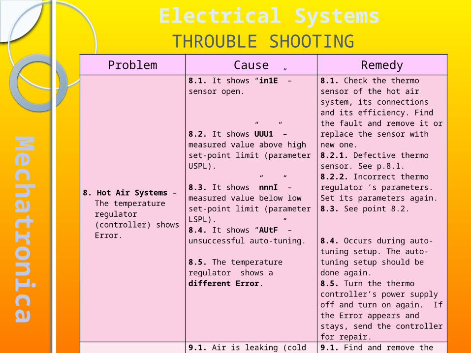
8. Hot Air Systems – The temperature regulator (controller) shows Error.
8.1. It shows “in1E” – sensor open.
8.2. It shows”UUU1” – measured value above high set-point limit (parameter USPL).
8.3. It shows ”nnnI” – measured value below low set-point limit (parameter LSPL).8.4. It shows “AUtF” – unsuccessful auto-tuning.
8.5. The temperature regulator shows a different Error.
8.1. Check the thermo sensor of the hot air system, its connections and its efficiency. Find the fault and remove it or replace the sensor with new one.8.2.1. Defective thermo sensor. See p.8.1.8.2.2. Incorrect thermo regulator ‘s parameters. Set its parameters again. 8.3. See point 8.2.
8.4. Occurs during auto-tuning setup. The auto-tuning setup should be done again.8.5. Turn the thermo controller’s power supply off and turn on again. If the Error appears and stays, send the controller for repair.
9. Hot Air Systems –Measured temperature PV varies greatly around the set temperature SV.
9.1. Air is leaking (cold or hot) before reaching the nozzle. 9.2. Big difference in the minimum air flow and work air flow.9.3. Incorectly set PID parameters of the Thermo-regulator.
9.1. Find and remove the fault.
9.2. Increase the minimum air input flow using its regulator valve.9.3. Start auto-tuning setup of the thermo-regulator. See “RT1800 User manual”.