Embed Size (px)
Citation preview

www.fairchildsemi.com
1
Power Solutions for Automotive Applications
Fairchild Automotive Team2008 April

2
Automotive Product Portfolio
Fairchild offers a broad array of automotive solutions and services for optimizing system power.
Power MOSFETs
Smart MOSFETs*
IGBTs
Ignition IGBTs
Smart Ignition IGBTs*
Rectifiers
Motor Driver
HV IC
Automotive Power Modules
* New Product Focus
3
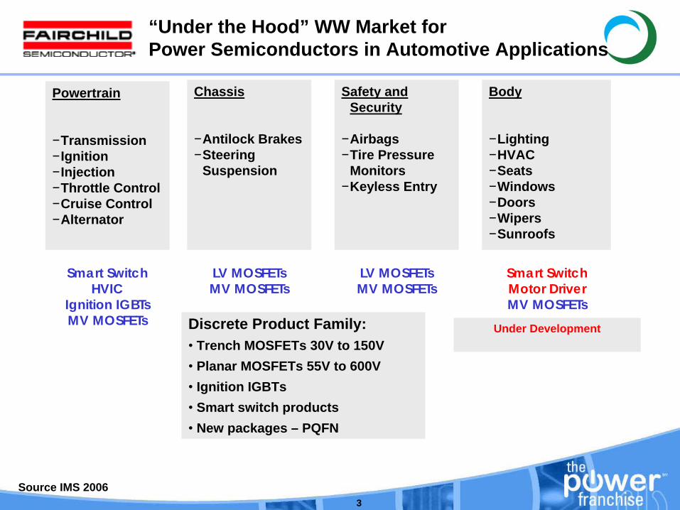
Powertrain
−Transmission−Ignition−Injection−Throttle Control−Cruise Control−Alternator
“Under the Hood” WW Market for Power Semiconductors in Automotive Applications
Chassis
−Antilock Brakes−Steering
Suspension
Safety and Security
−Airbags−Tire Pressure
Monitors−Keyless Entry
Body
−Lighting−HVAC−Seats−Windows−Doors−Wipers−Sunroofs
Under DevelopmentDiscrete Product Family:• Trench MOSFETs 30V to 150V• Planar MOSFETs 55V to 600V• Ignition IGBTs• Smart switch products• New packages – PQFN
Smart SwitchHVIC
Ignition IGBTsMV MOSFETs
LV MOSFETsMV MOSFETs
Smart SwitchMotor DriverMV MOSFETs
LV MOSFETsMV MOSFETs
Source IMS 2006

4
To become the “AUTOMOTIVE” POWER FRANCHISE
STRATEGIC IMPERATIVES• Provide world-class new products to our key automotive customers
Smart Power (High Side Switches, HV gate drivers, Ignition)Advanced Packaging (PQFN, Smart Power Module)
• Growth in target automotive applications in all regions• Deliver high standards of quality and continually reduce
manufacturing costs • Superior technical and customer service• Global presence/local leadership:
‒ Local design-in and demand creation ‒ Global fulfillment through OEM ODM EMS Distribution
Automotive Vision
5
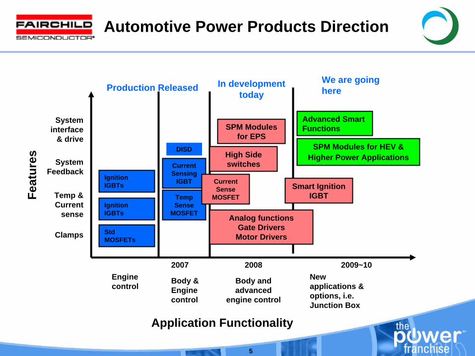
StdMOSFETs
Ignition IGBTs
Temp Sense
MOSFET
Advanced Smart Functions
Engine control
Body & Engine control
Body and advanced
engine control
New applications & options, i.e. Junction Box
Application Functionality
Clamps
Temp & Current
sense
System Feedback
System interface
& drive
Feat
ures
Production ReleasedWe are going here
In development today
Analog functionsGate Drivers
Motor Drivers
SPM Modules for EPS
Automotive Power Products Direction
Smart Ignition IGBT
DISD
2007
Current Sensing
IGBT
2008
High Side switches
SPM Modules for HEV & Higher Power Applications
2009~10
Current Sense
MOSFET
Ignition IGBTs
6
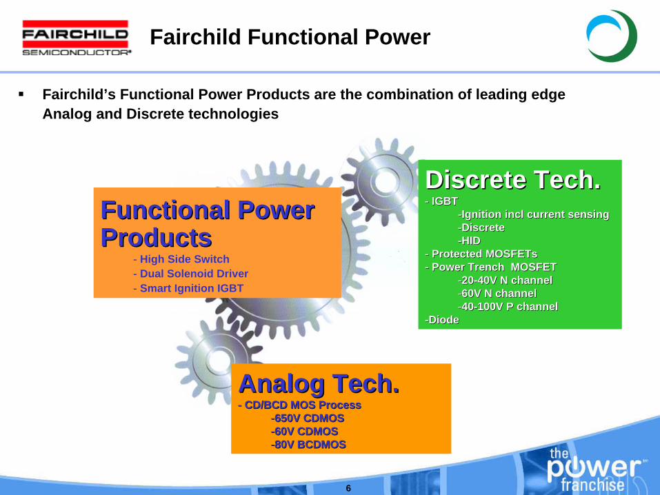
Fairchild Functional Power
Functional Power Functional Power ProductsProducts
- High Side Switch- Dual Solenoid Driver- Smart Ignition IGBT
Discrete Tech.Discrete Tech.-- IGBTIGBT
--Ignition Ignition inclincl current sensingcurrent sensing--DiscreteDiscrete--HIDHID
-- Protected Protected MOSFETsMOSFETs-- Power Trench MOSFETPower Trench MOSFET
--2020--40V N channel40V N channel--60V N channel60V N channel--4040--100V P channel100V P channel
--DiodeDiode
Analog Tech. Analog Tech. -- CD/BCD MOS Process CD/BCD MOS Process
--650V CDMOS650V CDMOS--60V CDMOS60V CDMOS--80V BCDMOS80V BCDMOS
Fairchild’s Functional Power Products are the combination of leading edgeAnalog and Discrete technologies
7
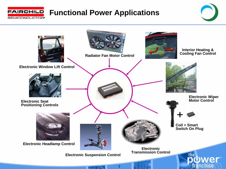
Coil + Smart Switch On Plug
Electronic Transmission Control
Interior Heating & Cooling Fan Control
Electronic Window Lift Control
Electronic Suspension Control
Electronic Wiper Motor Control
Radiator Fan Motor Control
Electronic Headlamp Control
Electronic Seat Positioning Controls
+
Functional Power Applications

8
Functional Power Benefits
Fairchild Benefit
Fairchild’s smart power switch technology allows the use on the lowest power loss (heat generating) devices that the footprint (board space) will allow.
Fairchild’s smart power switch technology enables faster development of new products optimized for a customer application.
Fairchild’s smart power switch technology allows for more accurate measurement of low voltage drops and currents.
Challenge
Heat removal in a small space is key issue in design of electronic modules for harsh automotive environment
Flexibility Most automotive designs are customized yet automotive system designers are under constant pressure to reduce design cycle time.
Performance Reduction of noise and accurate sensing of load conditions are important considerations in automotive module design.
Why Fairchild integrates the sense elements with power discrete products(Control IC or Resistors + Power Trench MOSFET, EcoSpark, or IGBT)

9
Functional Power Products Focus
High Side Switch
HV IC
Smart Ignition IGBT
Motor Driver
Solenoid Driver
10
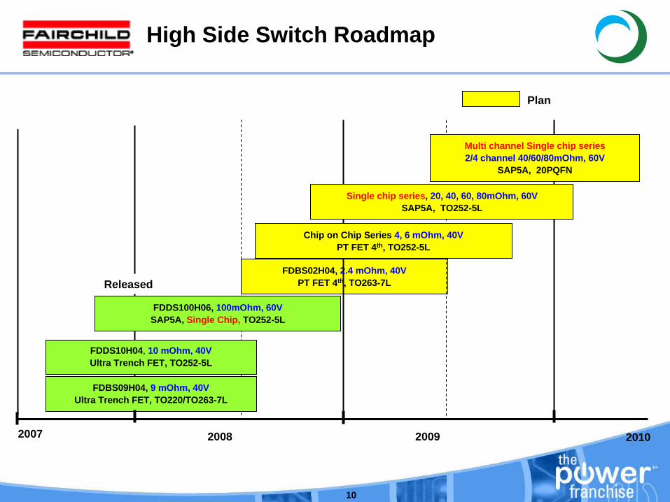
FDDS10H04, 10 mOhm, 40VUltra Trench FET, TO252-5L
FDBS02H04, 2.4 mOhm, 40VPT FET 4th, TO263-7L
FDBS09H04, 9 mOhm, 40VUltra Trench FET, TO220/TO263-7L
2008 20092007
FDDS100H06, 100mOhm, 60VSAP5A, Single Chip, TO252-5L
Plan
High Side Switch Roadmap
2010
Single chip series, 20, 40, 60, 80mOhm, 60VSAP5A, TO252-5L
Multi channel Single chip series2/4 channel 40/60/80mOhm, 60V
SAP5A, 20PQFN
Chip on Chip Series 4, 6 mOhm, 40VPT FET 4th, TO252-5L
Released
11
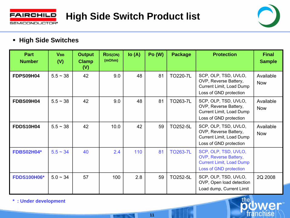
High Side Switch Product list
High Side Switches
PartNumber
VBB
(V)OutputClamp
(V)
RDS(ON)(mOhm)
Io (A) Po (W) Package Protection FinalSample
FDPS09H04 5.5 ~ 38 42 9.0 48 81 TO220-7L SCP, OLP, TSD, UVLO, OVP, Reverse Battery, Current Limit, Load DumpLoss of GND protection
AvailableNow
FDBS09H04 5.5 ~ 38 42 9.0 48 81 TO263-7L SCP, OLP, TSD, UVLO, OVP, Reverse Battery, Current Limit, Load DumpLoss of GND protection
AvailableNow
FDDS10H04 5.5 ~ 38 42 10.0 42 59 TO252-5L SCP, OLP, TSD, UVLO, OVP, Reverse Battery, Current Limit, Load DumpLoss of GND protection
AvailableNow
FDBS02H04* 5.5 ~ 34 40 2.4 110 81 TO263-7L SCP, OLP, TSD, UVLO, OVP, Reverse Battery, Current Limit, Load DumpLoss of GND protection
FDDS100H06* 5.0 ~ 34 57 100 2.8 59 TO252-5L SCP, OLP, TSD, UVLO, OVP, Open load detectionLoad dump, Current Limit
2Q 2008
* : Under development
12
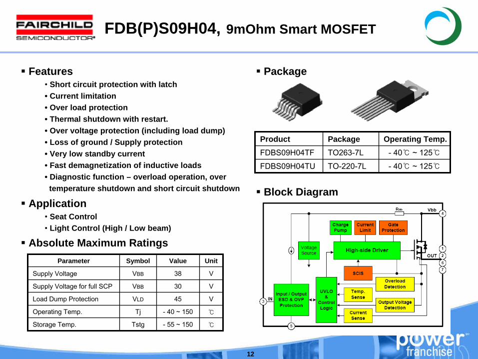
FDB(P)S09H04, 9mOhm Smart MOSFET
Features• Short circuit protection with latch• Current limitation• Over load protection• Thermal shutdown with restart.• Over voltage protection (including load dump)• Loss of ground / Supply protection• Very low standby current• Fast demagnetization of inductive loads• Diagnostic function – overload operation, over
temperature shutdown and short circuit shutdown
Application• Seat Control• Light Control (High / Low beam)
Product Package Operating Temp.FDBS09H04TF TO263-7L - 40 ~ 125
FDBS09H04TU TO-220-7L - 40 ~ 125
Package
Parameter Symbol Value Unit
Supply Voltage VBB 38 V
Supply Voltage for full SCP VBB 30 V
Load Dump Protection VLD 45 V
Operating Temp. Tj -
40 ~ 150
Storage Temp. Tstg -
55 ~ 150
Absolute Maximum Ratings
Block Diagram

13
FDDS10H04, 10mOhm Smart MOSFET
Features• Short circuit protection with latch• Current limitation• Over load protection• Thermal shutdown with restart.• Over voltage protection (including load dump)• Loss of ground / Supply protection• Very low standby current• Fast demagnetization of inductive loads• Diagnostic function – overload operation, over
temperature shutdown and short circuit shutdown
Application• Seat Control• Light Control (High / Low beam)
Product Package Operating Temp.FDDS10H04TF TO252-5L - 40 ~ 125
Package
Parameter Symbol Value Unit
Supply Voltage VBB 38 V
Supply Voltage for full SCP VBB 30 V
Load Dump Protection VLD 45 V
Operating Temp. Tj -
40 ~ 150
Storage Temp. Tstg -
55 ~ 150
Absolute Maximum Ratings
Block Diagram

14
FDBS02H04, 2.4mOhm Smart MOSFET
Features• Short circuit protection with latch• Current limitation• Over load protection• Thermal shutdown with restart.• Over voltage protection (including load dump)• Loss of ground / Supply protection• Very low standby current• Fast demagnetization of inductive loads• Diagnostic function – overload operation, over
temperature shutdown and short circuit shutdown
Application• Seat Control• Light Control (High / Low beam)
Product Package Operating Temp.FDBS02H04TF TO263-7L - 40 ~ 125
Package
Parameter Symbol Value Unit
Supply Voltage VBB 38 V
Supply Voltage for full SCP VBB 30 V
Load Dump Protection VLD 45 V
Operating Temp. Tj -
40 ~ 150
Storage Temp. Tstg -
55 ~ 150
Absolute Maximum Ratings
Block Diagram
15
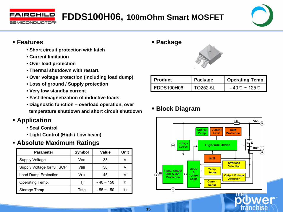
FDDS100H06, 100mOhm Smart MOSFET
Features• Short circuit protection with latch• Current limitation• Over load protection• Thermal shutdown with restart.• Over voltage protection (including load dump)• Loss of ground / Supply protection• Very low standby current• Fast demagnetization of inductive loads• Diagnostic function – overload operation, over
temperature shutdown and short circuit shutdown
Application• Seat Control• Light Control (High / Low beam)
Package
Parameter Symbol Value Unit
Supply Voltage VBB 38 V
Supply Voltage for full SCP VBB 30 V
Load Dump Protection VLD 45 V
Operating Temp. Tj -
40 ~ 150
Storage Temp. Tstg -
55 ~ 150
Absolute Maximum Ratings
Block Diagram
Product Package Operating Temp.FDDS100H06 TO252-5L - 40 ~ 125
16
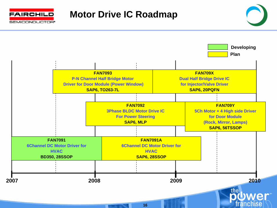
FAN7093 P-N Channel Half Bridge Motor
Driver for Door Module (Power Window)SAP6, TO263-7L
2007 2008 2009
FAN7092 3Phase BLDC Motor Drive IC
For Power SteeringSAP6, MLP
2010
FAN7091A 6Channel DC Motor Driver for
HVACSAP6, 28SSOP
FAN709Y 5Ch Motor + 4 High side Driver
for Door Module (Rock, Mirror, Lamps)
SAP6, 56TSSOP
FAN709X Dual Half Bridge Drive ICfor Injector/Valve Driver
SAP6, 20PQFN
Motor Drive IC Roadmap
PlanDeveloping
FAN7091 6Channel DC Motor Driver for
HVACBD350, 28SSOP
17
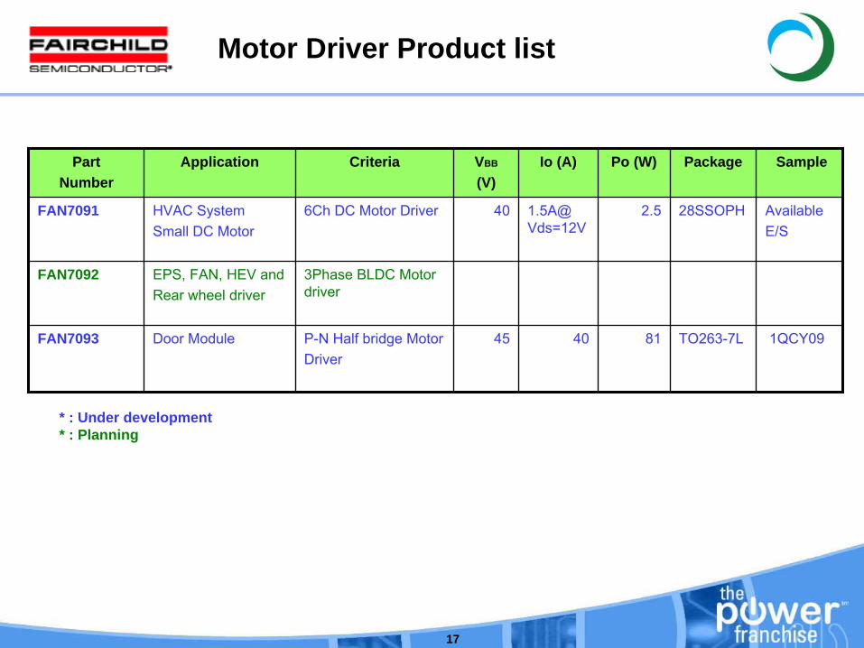
Motor Driver Product list
PartNumber
Application Criteria VBB
(V)Io (A) Po (W) Package Sample
FAN7091 HVAC SystemSmall DC Motor
6Ch DC
Motor Driver 40 1.5A@ Vds=12V
2.5 28SSOPH AvailableE/S
FAN7092 EPS, FAN, HEV andRear wheel driver
3Phase BLDC Motor driver
FAN7093 Door Module P-N Half bridge MotorDriver
45 40 81 TO263-7L 1QCY09
* : Under development* : Planning
18
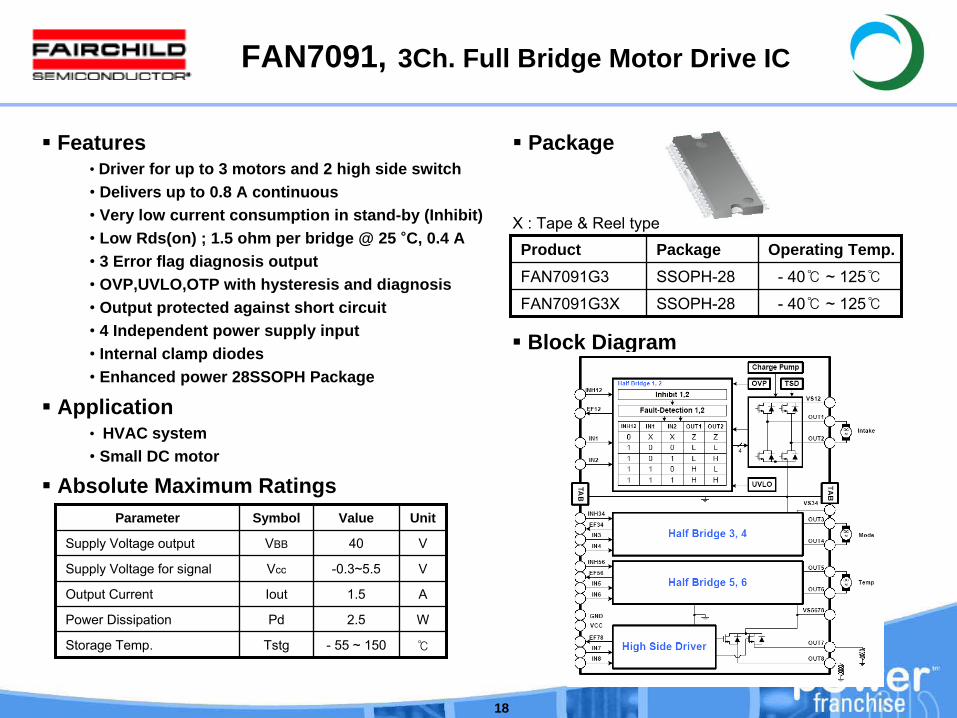
FAN7091, 3Ch. Full Bridge Motor Drive IC
Features• Driver for up to 3 motors and 2 high side switch• Delivers up to 0.8 A continuous• Very low current consumption in stand-by (Inhibit)• Low Rds(on) ; 1.5 ohm per bridge @ 25 °C, 0.4 A• 3 Error flag diagnosis output• OVP,UVLO,OTP with hysteresis and diagnosis• Output protected against short circuit• 4 Independent power supply input• Internal clamp diodes• Enhanced power 28SSOPH Package
Application• HVAC system• Small DC motor
Product Package Operating Temp.FAN7091G3 SSOPH-28 - 40 ~ 125
FAN7091G3X SSOPH-28 - 40 ~ 125
Package
Parameter Symbol Value Unit
Supply Voltage output VBB 40 V
Supply Voltage for signal Vcc -0.3~5.5 V
Output Current Iout 1.5 A
Power Dissipation Pd 2.5 W
Storage Temp. Tstg -
55 ~ 150
Absolute Maximum Ratings
Block Diagram
X : Tape & Reel type
19
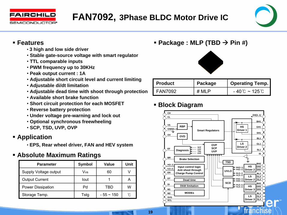
FAN7092, 3Phase BLDC Motor Drive IC
Features• 3 high and low side driver• Stable gate-source voltage with smart regulator• TTL comparable inputs• PWM frequency up to 30KHz• Peak output current : 1A• Adjustable short circuit level and current limiting• Adjustable di/dt limitation• Adjustable dead time with shoot through protection• Available short brake function• Short circuit protection for each MOSFET• Reverse battery protection• Under voltage pre-warning and lock out• Optional synchronous freewheeling• SCP, TSD, UVP, OVP
Application• EPS, Rear wheel driver, FAN and HEV system
Parameter Symbol Value Unit
Supply Voltage output Vvs 60 V
Output Current Iout 1 A
Power Dissipation Pd TBD W
Storage Temp. Tstg -
55 ~ 150
Absolute Maximum Ratings
Block Diagram
Product Package Operating Temp.FAN7092 # MLP - 40 ~ 125
Package : MLP (TBD Pin #)
CH
HSDriver 1
REG1
REG2
LSDriver 2
UVLO
OVPSCPUVP
Input control logic Anti shoot through
Charge Pump Control BL[3..1]SL[3..1]
BH[3..1]SH[3..1]
SCDDL[3..1]SL[3..1]
DH[3..1]SH[3..1]
TSD
Diagnosis
DI/dt limitation
SCPUVPTSDOVP
RBP
OVD
HSDriver 2
LSDriver 2
HSDriver 3
LSDriver 3
Dead time
Brake Selection
CL
VS
GND[3..1]
OV
EF
BR
IH[3..1]
IL[3..1]
EN
DT
DI
SVGSCL SL3
GL3BL3
SH3GH3BH3
SL2GL2BL2
SH2GH2BH2
SH1
GH1
BH1
SL1
GL1
BL1
IS
MODEsM1
M2
DH[3..1]
Smart Regulators
20
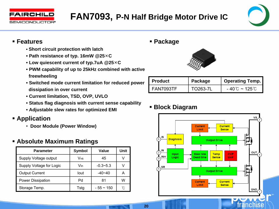
FAN7093, P-N Half Bridge Motor Drive IC
Features• Short circuit protection with latch• Path resistance of typ. 16mW @25×C• Low quiescent current of typ.7uA @25×C• PWM capability of up to 25kHz combined with active
freewheeling• Switched mode current limitation for reduced power
dissipation in over current• Current limitation, TSD, OVP, UVLO• Status flag diagnosis with current sense capability• Adjustable slew rates for optimized EMI
Application• Door Module (Power Window)
Parameter Symbol Value Unit
Supply Voltage output Vvs 45 V
Supply Voltage for Logic Vin -0.3~5.3 V
Output Current Iout -40~40 A
Power Dissipation Pd 81 W
Storage Temp. Tstg -
55 ~ 150
Absolute Maximum Ratings
Block Diagram
Product Package Operating Temp.FAN7093TF TO263-7L - 40 ~ 125
Package
21
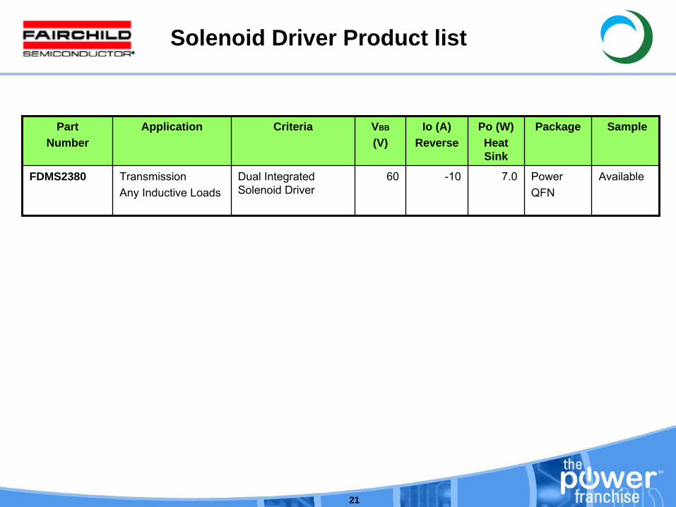
Solenoid Driver Product list
PartNumber
Application Criteria VBB
(V)Io (A)
ReversePo (W)Heat Sink
Package Sample
FDMS2380 TransmissionAny Inductive Loads
Dual Integrated Solenoid Driver
60 -10 7.0 PowerQFN
Available

22
FDMS2380, Dual Integrated Solenoid Driver
Features• 10A, 60V load clamp• RDS(ON) = 30mΩ
(Typ.) Excitation path• 6V to 26V operation• Soft short detection• CMOS Compatible• Thermal Shutdown• Diagnostic Output• Integrated Clamps• Over Current Protection• Open Load Detection• Over Voltage Protection
Application• Transmission/Inductive Loads
Package
Parameter Symbol Value Unit
Max. DC Supply Voltage VBAT 60 V
Input Voltage VIN 10 V
Reverse Output Current IIN -10 A
Operating Temp. Tj -
40 ~ 160
Storage Temp. Tstg -
40 ~ 160
Absolute Maximum Ratings
Block Diagram
Product Package Reel Size Tape Width QuantityFDMS2380 Power PQN 330mm 24mm 750
23
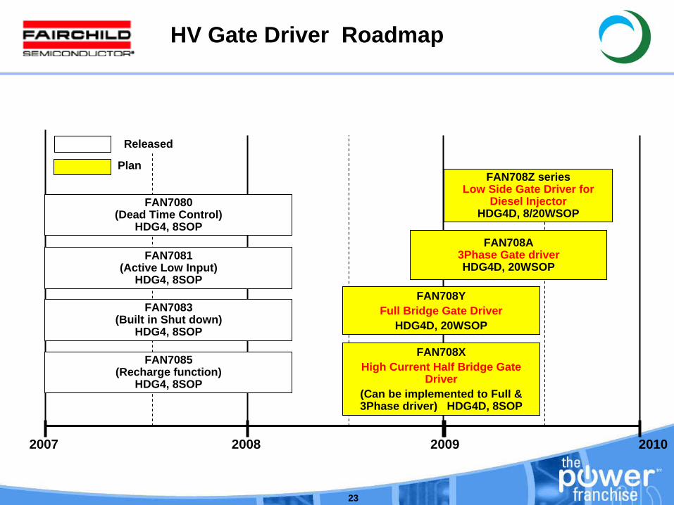
FAN7081(Active Low Input)
HDG4, 8SOP
FAN7083(Built in Shut down)
HDG4, 8SOP
FAN7080(Dead Time Control)
HDG4, 8SOP
FAN7085(Recharge function)
HDG4, 8SOP
2007 2008 2009 2010
FAN708Y Full Bridge Gate Driver
HDG4D, 20WSOP
FAN708A3Phase Gate driverHDG4D, 20WSOP
FAN708Z seriesLow Side Gate Driver for
Diesel Injector HDG4D, 8/20WSOP
HV Gate Driver Roadmap
FAN708X High Current Half Bridge Gate
Driver(Can be implemented to Full & 3Phase driver) HDG4D, 8SOP
Plan
Released
24
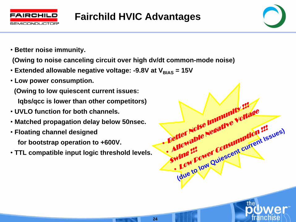
•
Better noise immunity. (Owing to noise canceling circuit over high dv/dt common-mode noise)
• Extended allowable negative voltage: -9.8V at VBIAS = 15V• Low power consumption.
(Owing to low quiescent current issues:Iqbs/qcc is lower than other competitors)
• UVLO function for both channels.• Matched propagation delay below 50nsec.• Floating channel designed
for bootstrap operation to +600V.• TTL compatible input logic threshold levels.
Fairchild HVIC Advantages
•• Better Noise immunity !!!
Better Noise immunity !!!
•• Allowable Negative Voltage
Allowable Negative Voltage
Swing !!!
Swing !!!
•• Low Power Consumption !!!
Low Power Consumption !!!
(due to low Quiescent current Issues)
25
HV IC Summary 1
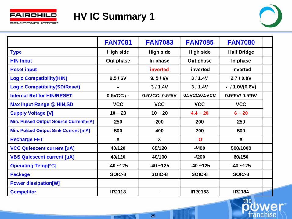
FAN7081 FAN7083 FAN7085 FAN7080Type High side High side High side Half Bridge
HIN Input Out phase In phase Out phase In phase
Reset input - inverted inverted inverted
Logic Compatibility(HIN) 9.5 / 6V 9. 5 / 6V 3 / 1.4V 2.7 / 0.8V
Logic Compatibility(SD/Reset) - 3 / 1.4V 3 / 1.4V - / 1.0V(0.6V)
Internal Ref for HIN/RESET 0.5VCC / - 0.5VCC/ 0.5*5V 0.5VCC/0.5VCC 0.5*5V/ 0.5*5V
Max Input Range @ HIN,SD VCC VCC VCC VCC
Supply Voltage [V] 10 ~ 20 10 ~ 20 4.4 ~ 20 6 ~ 20Min. Pulsed Output Source Current[mA] 250 200 200 250
Min. Pulsed Output Sink Current [mA] 500 400 200 500
Recharge FET X X O X
VCC Quiescent current [uA] 40/120 65/120 -/400 500/1000
VBS Quiescent current [uA] 40/120 40/100 -/200 60/150
Operating Temp[°C] -40 ~125 -40 ~125 -40 ~125 -40 ~125
Package SOIC-8 SOIC-8 SOIC-8 SOIC-8
Power dissipation[W]
Competitor IR2118 - IR20153 IR2184
26
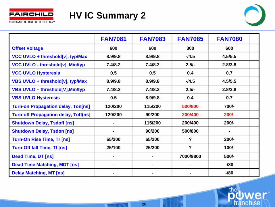
FAN7081 FAN7083 FAN7085 FAN7080Offset Voltage 600 600 300 600
VCC UVLO + threshold[v], typ/Max 8.9/9.8 8.9/9.8 -/4.5 4.5/5.5
VCC UVLO - threshold[v], Min/typ 7.4/8.2 7.4/8.2 2.5/- 2.8/3.8
VCC UVLO Hysteresis 0.5 0.5 0.4 0.7
VBS UVLO + threshold[v], typ/Max 8.9/9.8 8.9/9.8 -/4.5 4.5/5.5
VBS UVLO – threshold[V],Min/typ 7.4/8.2 7.4/8.2 2.5/- 2.8/3.8
VBS UVLO Hysteresis 0.5 8.9/9.8 0.4 0.7
Turn-on Propagation delay, Ton[ns] 120/200 115/200 500/800 700/-
Turn-off Propagation delay, Toff(ns] 120/200 90/200 200/400 200/-
Shutdown Delay, Tsdoff [ns] - 115/200 200/400 200/-
Shutdown Delay, Tsdon [ns] - 90/200 500/800 -
Turn-On Rise Time, Tr [ns] 65/200 65/200 ? 200/-
Turn-Off fall Time, Tf [ns] 25/100 25/200 ? 100/-
Dead Time, DT [ns] - - 7000/9800 500/-
Dead Time Matching, MDT [ns] - - - -/80
Delay Matching, MT [ns] - - - -/80
HV IC Summary 2
27
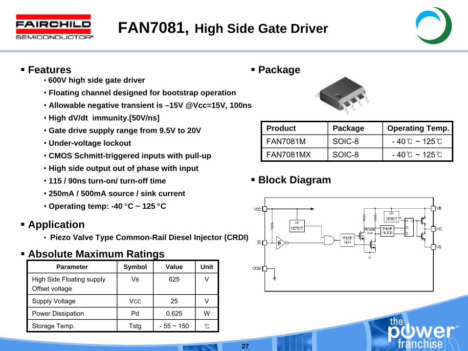
FAN7081, High Side Gate Driver
Features• 600V high side gate driver• Floating channel designed for bootstrap operation• Allowable negative transient is –15V @Vcc=15V, 100ns• High dV/dt immunity.[50V/ns]• Gate drive supply range from 9.5V to 20V• Under-voltage lockout• CMOS Schmitt-triggered inputs with pull-up• High side output out of phase with input• 115 / 90ns turn-on/ turn-off time• 250mA / 500mA source / sink current• Operating temp: -40 °C ~ 125 °C
Application• Piezo Valve Type Common-Rail Diesel Injector (CRDI)
Product Package Operating Temp.FAN7081M SOIC-8 - 40 ~ 125
FAN7081MX SOIC-8 - 40 ~ 125
Package
Parameter Symbol Value Unit
High Side Floating supply Offset voltage
VB 625 V
Supply Voltage VCC 25 V
Power Dissipation Pd 0.625 W
Storage Temp. Tstg -
55 ~ 150
Absolute Maximum Ratings
Block Diagram
28
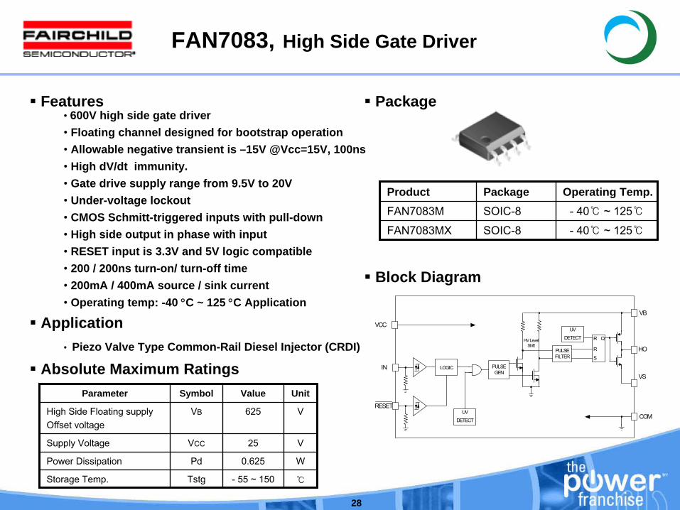
FAN7083, High Side Gate Driver
Features• 600V high side gate driver• Floating channel designed for bootstrap operation• Allowable negative transient is –15V @Vcc=15V, 100ns• High dV/dt immunity.• Gate drive supply range from 9.5V to 20V• Under-voltage lockout• CMOS Schmitt-triggered inputs with pull-down• High side output in phase with input • RESET input is 3.3V and 5V logic compatible• 200 / 200ns turn-on/ turn-off time• 200mA / 400mA source / sink current• Operating temp: -40 °C ~ 125 °C Application
Application• Piezo Valve Type Common-Rail Diesel Injector (CRDI)
Product Package Operating Temp.FAN7083M SOIC-8 - 40 ~ 125
FAN7083MX SOIC-8 - 40 ~ 125
Package
Parameter Symbol Value Unit
High Side Floating supply Offset voltage
VB 625 V
Supply Voltage VCC 25 V
Power Dissipation Pd 0.625 W
Storage Temp. Tstg -
55 ~ 150
Absolute Maximum Ratings
Block Diagram
PULSE GEN
UVDETECT
UVDETECT
PULSEFILTER
R
R
S
QHV Level Shift
IN
RESET
VB
HO
VS
COM
VCC
LOGIC
29
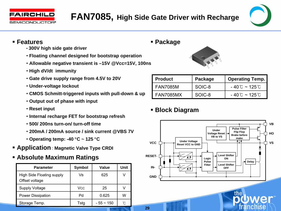
FAN7085, High Side Gate Driver with Recharge
Features• 300V high side gate driver• Floating channel designed for bootstrap operation• Allowable negative transient is –15V @Vcc=15V, 100ns• High dV/dt immunity • Gate drive supply range from 4.5V to 20V• Under-voltage lockout• CMOS Schmitt-triggered inputs with pull-down & up • Output out of phase with input• Reset input• Internal recharge FET for bootstrap refresh• 500/ 200ns turn-on/ turn-off time• 200mA / 200mA source / sink current @VBS 7V• Operating temp: -40 °C ~ 125 °C
Application : Magnetic Valve Type CRDI
Product Package Operating Temp.FAN7085M SOIC-8 - 40 ~ 125
FAN7085MX SOIC-8 - 40 ~ 125
Package
Parameter Symbol Value Unit
High Side Floating supply Offset voltage
VB 625 V
Supply Voltage VCC 25 V
Power Dissipation Pd 0.625 W
Storage Temp. Tstg -
55 ~ 150
Absolute Maximum Ratings
Block Diagram
VCC Under Voltage Reset VCC to GND
Logic PulseFilter
Level ShifterON
Level ShifterOFF
Delay
Under Voltage Reset
VB to VS
Pulse FilterFlip Flop
Brake before make
RESET-
IN-
GND
VS
HO
VB
30
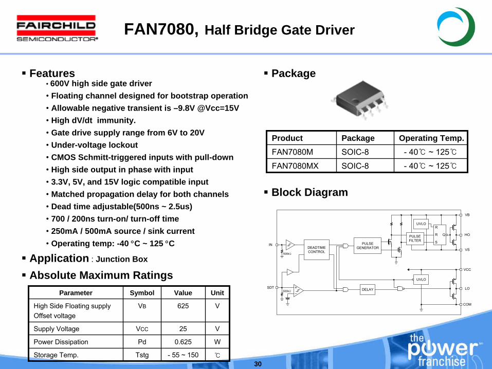
FAN7080, Half Bridge Gate Driver
Features• 600V high side gate driver• Floating channel designed for bootstrap operation• Allowable negative transient is –9.8V @Vcc=15V• High dV/dt immunity.• Gate drive supply range from 6V to 20V• Under-voltage lockout• CMOS Schmitt-triggered inputs with pull-down• High side output in phase with input • 3.3V, 5V, and 15V logic compatible input • Matched propagation delay for both channels• Dead time adjustable(500ns ~ 2.5us)• 700 / 200ns turn-on/ turn-off time• 250mA / 500mA source / sink current• Operating temp: -40 °C ~ 125 °C
Application : Junction Box
Product Package Operating Temp.FAN7080M SOIC-8 - 40 ~ 125
FAN7080MX SOIC-8 - 40 ~ 125
Package
Parameter Symbol Value Unit
High Side Floating supply Offset voltage
VB 625 V
Supply Voltage VCC 25 V
Power Dissipation Pd 0.625 W
Storage Temp. Tstg -
55 ~ 150
Absolute Maximum Ratings
Block Diagram
DEADTIMECONTROL
DELAY
PULSEGENERATOR
PULSEFILTER
UVLOR
R
S
Q
UVLO
VCC
COM
LO
VB
HO
VSIN
SDT500kΩ
500kΩ
31
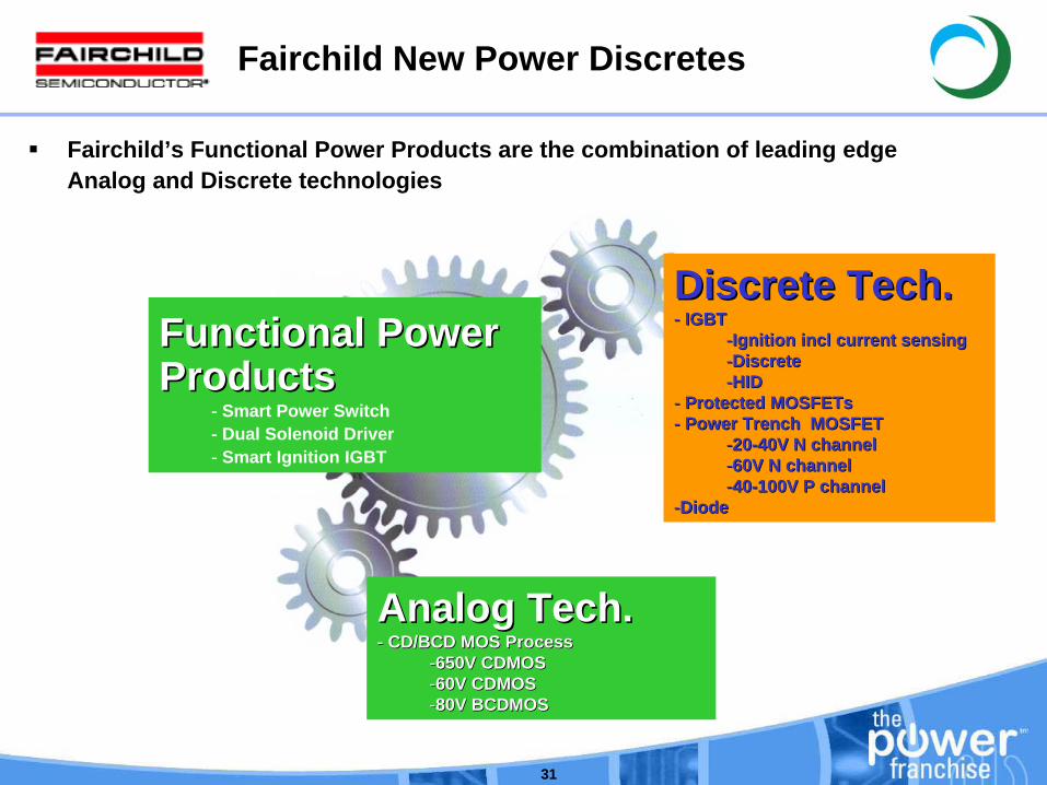
Fairchild New Power Discretes
Functional Power Functional Power ProductsProducts
- Smart Power Switch- Dual Solenoid Driver- Smart Ignition IGBT
Discrete Tech.Discrete Tech.-- IGBTIGBT
--Ignition Ignition inclincl current sensingcurrent sensing--DiscreteDiscrete--HIDHID
-- Protected Protected MOSFETsMOSFETs-- Power Trench MOSFETPower Trench MOSFET
--2020--40V N channel40V N channel--60V N channel60V N channel--4040--100V P channel100V P channel
--DiodeDiode
Analog Tech. Analog Tech. -- CD/BCD MOS Process CD/BCD MOS Process
--650V CDMOS650V CDMOS--60V CDMOS60V CDMOS--80V BCDMOS80V BCDMOS
Fairchild’s Functional Power Products are the combination of leading edgeAnalog and Discrete technologies
32
Explanation of Sense Elements
•
Current SenseA defined source/emitter isolated area on the power device called a pilot FET/IGBT. This sense element will yield a proportional sampling of the power device current.
•
Temperature Sense, three approaches used:–
Polysilicon temperature sense diodes: A known current is passed through the diode and the forward voltage drop of the diode is measured. As device heats up the Vf drops.
–
MOSFET Vth can be used for temperature sensing. A pilot FET is used with a known gate voltage that will pass a fixed drain current. As the device heats up the Vth drops and the current increases.
–
Control die also have the ability to sense temperature directly. Power and control die must be in close proximity to one another.
•
ESD polysilicon zener diodes that protect the gate of the MOSFET.
•
Clamp diodes Improved SCIS vs. UIS. polysilicon zener diodes and resistors configured between drain/collector, gate, source/emitter such that if VDS /VCE rise above the zener voltage the power device is turned on in the linear mode to dissipate the energy.
33
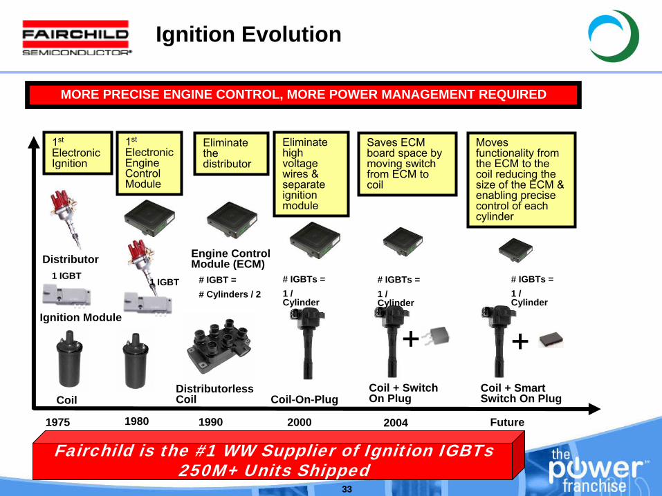
Ignition Evolution
Distributor
Coil
1975 1980 1990 2000 2004 Future
Ignition Module
Engine Control Module (ECM)
MORE PRECISE ENGINE CONTROL, MORE POWER MANAGEMENT REQUIRED
Coil-On-PlugCoil + Switch On Plug
Distributorless Coil
Coil + Smart Switch On Plug
+ +
1st
Electronic Ignition
Eliminate the distributor
Eliminate high voltage wires & separate ignition module
Moves functionality from the ECM to the coil reducing the size of the ECM & enabling precise control of each cylinder
Saves ECM board space by moving switch from ECM to coil
1st
Electronic Engine Control Module
# IGBT =# Cylinders / 2
# IGBTs =1 / Cylinder
# IGBTs =1 / Cylinder
# IGBTs =1 / Cylinder
1 IGBT1 IGBT
Fairchild is the #1 WW Supplier of Ignition IGBTs250M+ Units Shipped
34
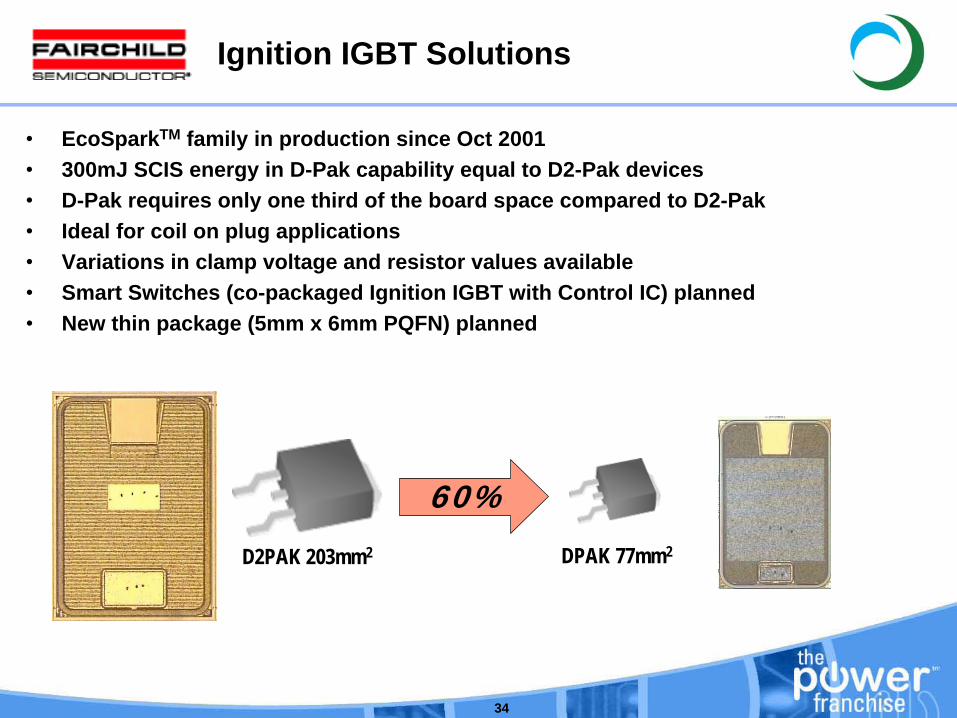
Ignition IGBT Solutions
•
EcoSparkTM family in production since Oct 2001•
300mJ SCIS energy in D-Pak capability equal to D2-Pak devices•
D-Pak requires only one third of the board space compared to D2-Pak•
Ideal for coil on plug applications•
Variations in clamp voltage and resistor values available•
Smart Switches (co-packaged Ignition IGBT with Control IC) planned•
New thin package (5mm x 6mm PQFN) planned
60%D2PAK 203mm2 DPAK 77mm2
35
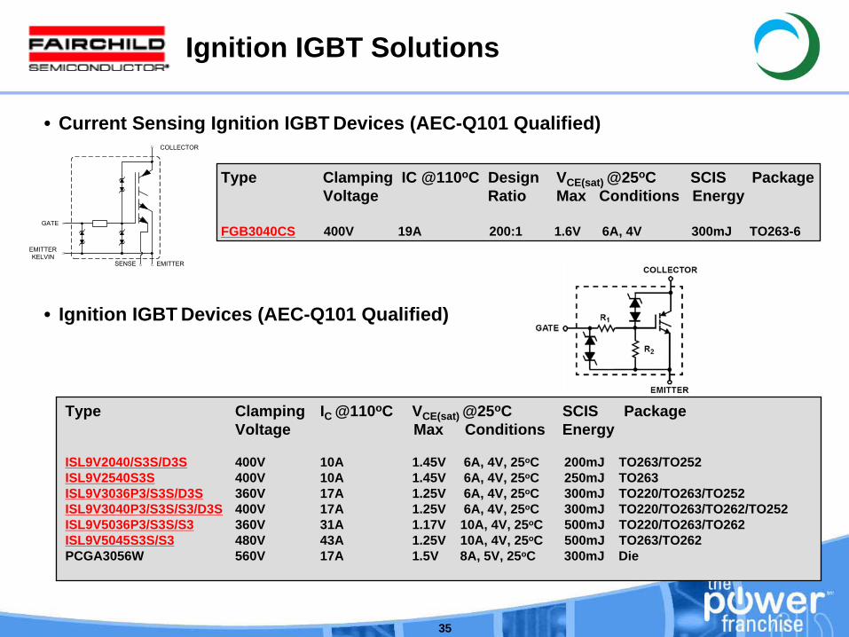
Ignition IGBT Solutions
• Current Sensing Ignition IGBT Devices (AEC-Q101 Qualified)
Type Clamping IC @110oC Design VCE(sat) @25oC SCIS PackageVoltage Ratio Max Conditions Energy
FGB3040CS 400V 19A 200:1 1.6V 6A, 4V 300mJ TO263-6
COLLECTOR
EMITTERSENSE
GATE
EMITTERKELVIN
• Ignition IGBT Devices (AEC-Q101 Qualified)
Type Clamping IC @110oC VCE(sat) @25oC SCIS Package Voltage Max Conditions Energy
ISL9V2040/S3S/D3S 400V 10A 1.45V 6A, 4V, 25oC 200mJ TO263/TO252ISL9V2540S3S 400V 10A 1.45V 6A, 4V, 25oC 250mJ TO263 ISL9V3036P3/S3S/D3S 360V 17A 1.25V 6A, 4V, 25oC 300mJ TO220/TO263/TO252ISL9V3040P3/S3S/S3/D3S 400V 17A 1.25V 6A, 4V, 25oC 300mJ TO220/TO263/TO262/TO252ISL9V5036P3/S3S/S3 360V 31A 1.17V 10A, 4V, 25oC 500mJ TO220/TO263/TO262 ISL9V5045S3S/S3 480V 43A 1.25V 10A, 4V, 25oC 500mJ TO263/TO262 PCGA3056W 560V 17A 1.5V 8A, 5V, 25oC 300mJ Die
36
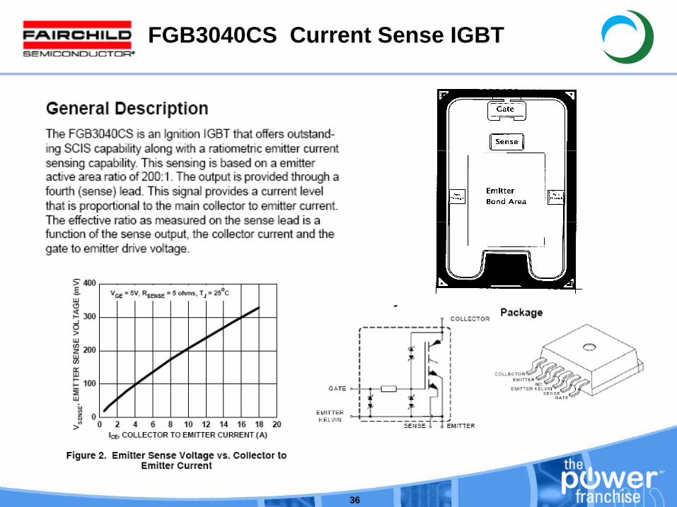
FGB3040CS Current Sense IGBT
37
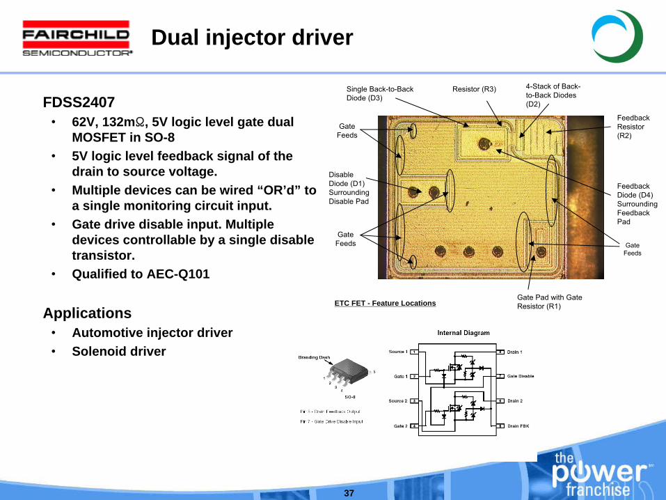
Dual injector driver
FDSS2407•
62V, 132mΩ, 5V logic level gate dual MOSFET in SO-8
•
5V logic level feedback signal of the drain to source voltage.
•
Multiple devices can be wired “OR’d” to a single monitoring circuit input.
•
Gate drive disable input. Multiple devices controllable by a single disable transistor.
•
Qualified to AEC-Q101
Applications•
Automotive injector driver•
Solenoid driver
Gate Pad with Gate Resistor (R1)
Disable Diode (D1) Surrounding Disable Pad
4-Stack of Back-
to-Back Diodes (D2)
Feedback Resistor (R2)
Feedback Diode (D4) Surrounding Feedback Pad
Resistor (R3)Single Back-to-Back Diode (D3)
ETC FET - Feature Locations
Gate Feeds
Gate Feeds
Gate Feeds

38
Fairchild Temperature Sensing MOSFET
39
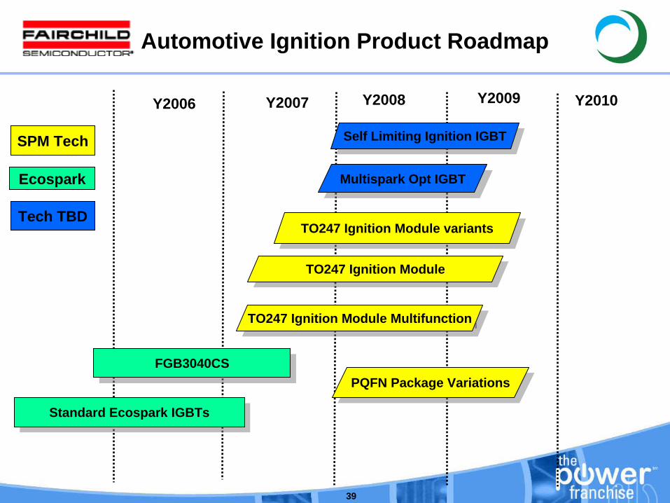
Y2006 Y2007 Y2008 Y2010
Automotive Ignition Product Roadmap
Y2009
FGB3040CSFGB3040CS
Standard Ecospark IGBTsStandard Ecospark IGBTs
TO247 Ignition Module MultifunctionTO247 Ignition Module Multifunction
TO247 Ignition ModuleTO247 Ignition Module
TO247 Ignition Module variantsTO247 Ignition Module variants
Self Limiting Ignition IGBTSelf Limiting Ignition IGBT
Multispark Opt IGBTMultispark Opt IGBT
SPM Tech
Ecospark
Tech TBD
PQFN Package VariationsPQFN Package Variations
40
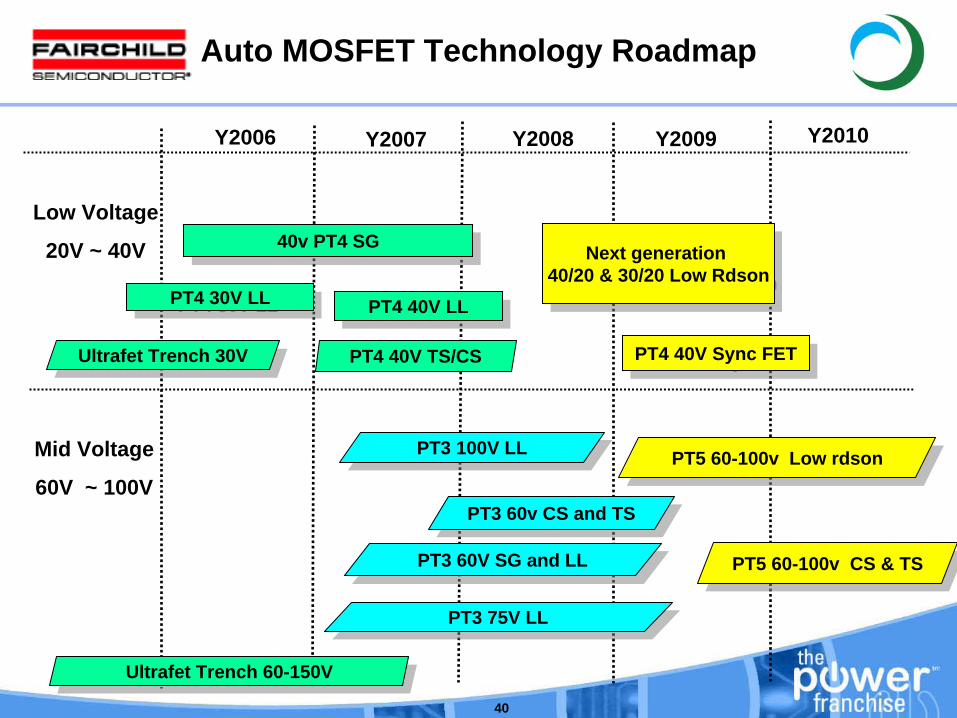
Y2006 Y2007
Auto MOSFET Technology Roadmap
Y2008 Y2010Y2009
Low Voltage
20V ~ 40V
Ultrafet Trench 30VUltrafet Trench 30V
PT4 30V LLPT4 30V LL
40v PT4 SG40v PT4 SG
PT4 40V LLPT4 40V LL
PT4 40V TS/CS
Next generation 40/20 & 30/20 Low Rdson
Next generation 40/20 & 30/20 Low Rdson
PT4 40V Sync FETPT4 40V Sync FET
Mid Voltage
60V ~ 100V
Ultrafet Trench 60-150VUltrafet Trench 60-150V
PT3 100V LLPT3 100V LL
PT3 60V SG and LLPT3 60V SG and LL
PT3 75V LLPT3 75V LL
PT5 60-100v Low rdsonPT5 60-100v Low rdson
PT3 60v CS and TSPT3 60v CS and TS
PT5 60-100v CS & TSPT5 60-100v CS & TS

www.fairchildsemi.com
41
Package
42
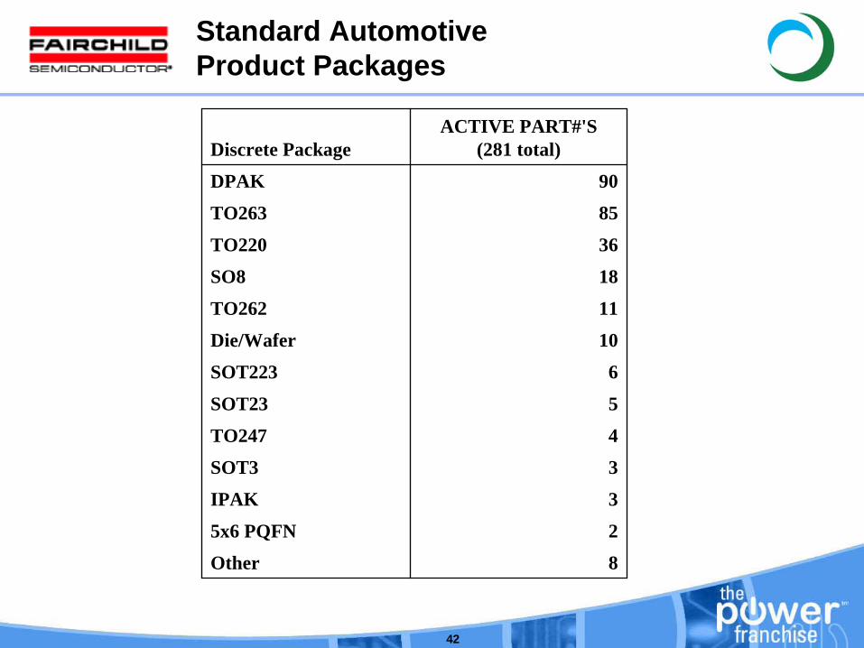
Standard Automotive Product Packages
Discrete PackageACTIVE PART#'S
(281 total)
DPAK 90
TO263 85
TO220 36
SO8 18
TO262 11
Die/Wafer 10
SOT223 6
SOT23 5
TO247 4
SOT3 3
IPAK 3
5x6 PQFN 2
Other 8
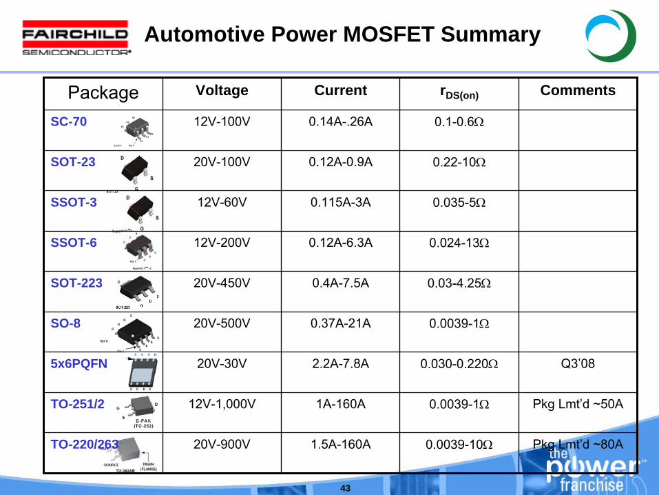
43
Package Voltage Current rDS(on) Comments
SC-70 12V-100V 0.14A-.26A 0.1-0.6Ω
SOT-23 20V-100V 0.12A-0.9A 0.22-10Ω
SSOT-3 12V-60V 0.115A-3A 0.035-5Ω
SSOT-6 12V-200V 0.12A-6.3A 0.024-13Ω
SOT-223 20V-450V 0.4A-7.5A 0.03-4.25Ω
SO-8 20V-500V 0.37A-21A 0.0039-1Ω
5x6PQFN 20V-30V 2.2A-7.8A 0.030-0.220Ω Q3’08
TO-251/2 12V-1,000V 1A-160A 0.0039-1Ω Pkg
Lmt’d
~50A
TO-220/263 20V-900V 1.5A-160A 0.0039-10Ω Pkg
Lmt’d
~80A
Automotive Power MOSFET Summary

44
5 x 6 PQFN @ 175C under development
•
PQFN (Power Quad Flat No-Leads)•
Package design is driven by module size reduction higher power density required•
Max TJ > 175°C minimize RθJC
•
Lower inductance lower capacitance•
Minimize package footprint maximize current density•
Lower system cost
•
5x6 PQFN•
Max Die Size 132 x 124 x 8 mils•
(3.35 x 3.15 x 0.2mm)•
Max Wire Diam 8mil aluminum source wires•
Wirebond Al wedge bonding•
6 x 8mil (source)•
1 x 5mil (gate)•
EMC Green EMC TBD
PQFN vs. SO-8
45
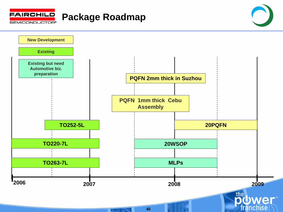
2007 2008 20092006
TO220-7L
TO252-5L
PQFN 2mm thick in Suzhou
PQFN 1mm thick Cebu Assembly
Existing
New Development
TO263-7L
20PQFN
20WSOP
MLPs
Existing but need Automotive biz.
preparation
Package Roadmap
www.fairchildsemi.com
46
By application

47
Power Steering Solutions
•
40V MOSFET technology using Fairchild’s PowerTrench technology•
Qualified to AEC-Q101•
Low RDS(on) for system efficiency and size-offering 2.2mΩ, 2.6mΩ, 4.0mΩ, and 5.2mΩ
version•
Available in TO220 and TO263 (D2-Pak) packages, or as die
Fairchild Confidential
•12V SystemsFDB8441 TO263 FDB8860 FDB8832FDP8441 TO220 FDP8860 FDP883240V SG / 2.2mΩ
30V LL/ 2.6mΩ
30V LL/ 2.2mΩ
• 42V SystemsFDB045AN08A0 TO263FDP047AN08A0 TO220 75V / 4.5,4.7mΩ
48
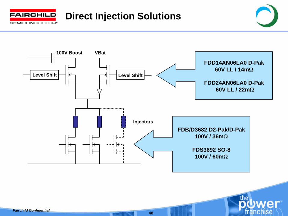
Direct Injection Solutions
Level Shift Level Shift
100V Boost VBat
InjectorsFDB/D3682 D2-Pak/D-Pak
100V / 36mΩ
FDS3692 SO-8 100V / 60mΩ
FDD14AN06LA0 D-Pak 60V LL / 14mΩ
FDD24AN06LA0 D-Pak 60V LL / 22mΩ
Fairchild Confidential
49
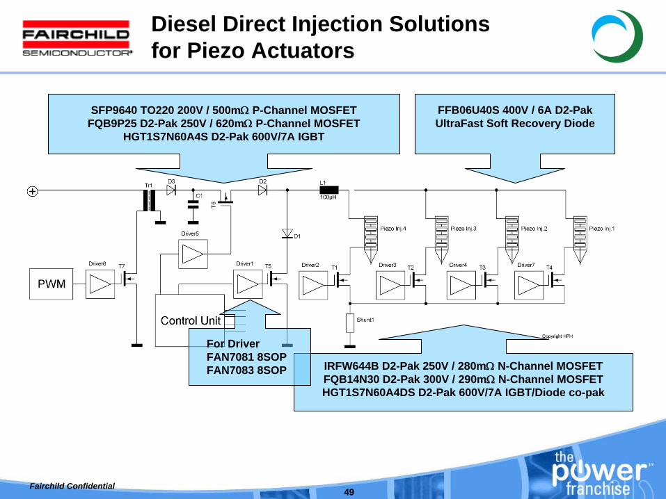
Diesel Direct Injection Solutions for Piezo Actuators
SFP9640 TO220 200V / 500mΩ
P-Channel MOSFETFQB9P25 D2-Pak 250V / 620mΩ
P-Channel MOSFET HGT1S7N60A4S D2-Pak 600V/7A IGBT
IRFW644B D2-Pak 250V / 280mΩ
N-Channel MOSFET FQB14N30 D2-Pak 300V / 290mΩ
N-Channel MOSFET HGT1S7N60A4DS D2-Pak 600V/7A IGBT/Diode co-pak
FFB06U40S 400V / 6A D2-PakUltraFast Soft Recovery Diode
Fairchild Confidential
For DriverFAN7081 8SOPFAN7083 8SOP
50
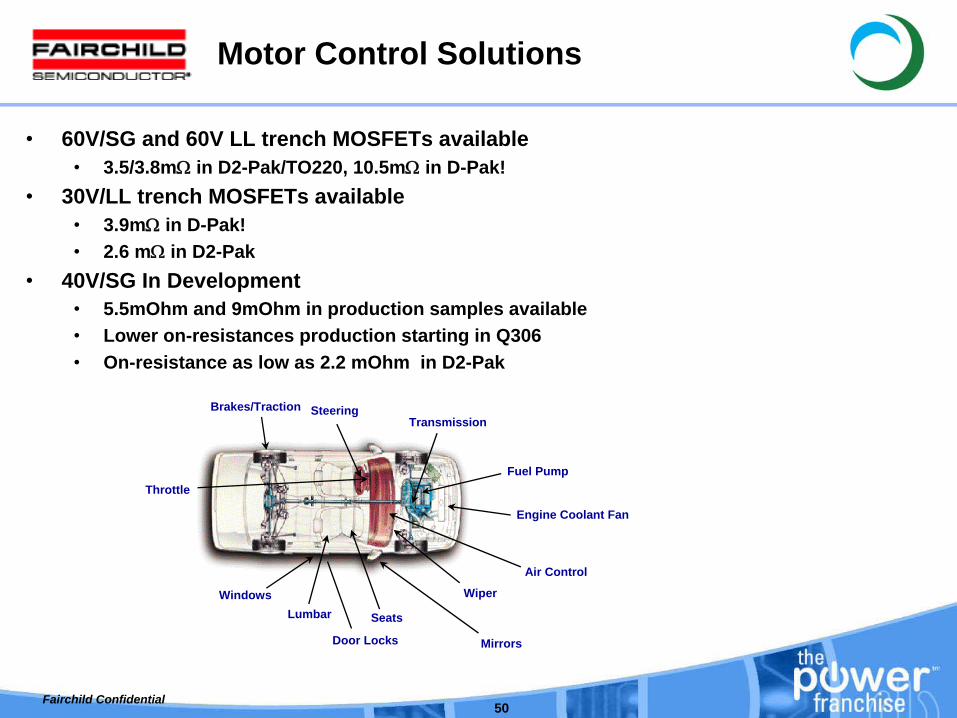
Motor Control Solutions
•
60V/SG and 60V LL trench MOSFETs available•
3.5/3.8mΩ
in D2-Pak/TO220, 10.5mΩ
in D-Pak! •
30V/LL trench MOSFETs available •
3.9mΩ
in D-Pak!•
2.6 mΩ
in D2-Pak•
40V/SG In Development •
5.5mOhm and 9mOhm in production samples available•
Lower on-resistances production starting in Q306•
On-resistance as low as 2.2 mOhm in D2-Pak
Seats
Windows
Mirrors
TransmissionSteering
Lumbar
Door Locks
Wiper
Air Control
ThrottleFuel Pump
Brakes/Traction
Engine Coolant Fan
Fairchild Confidential
51
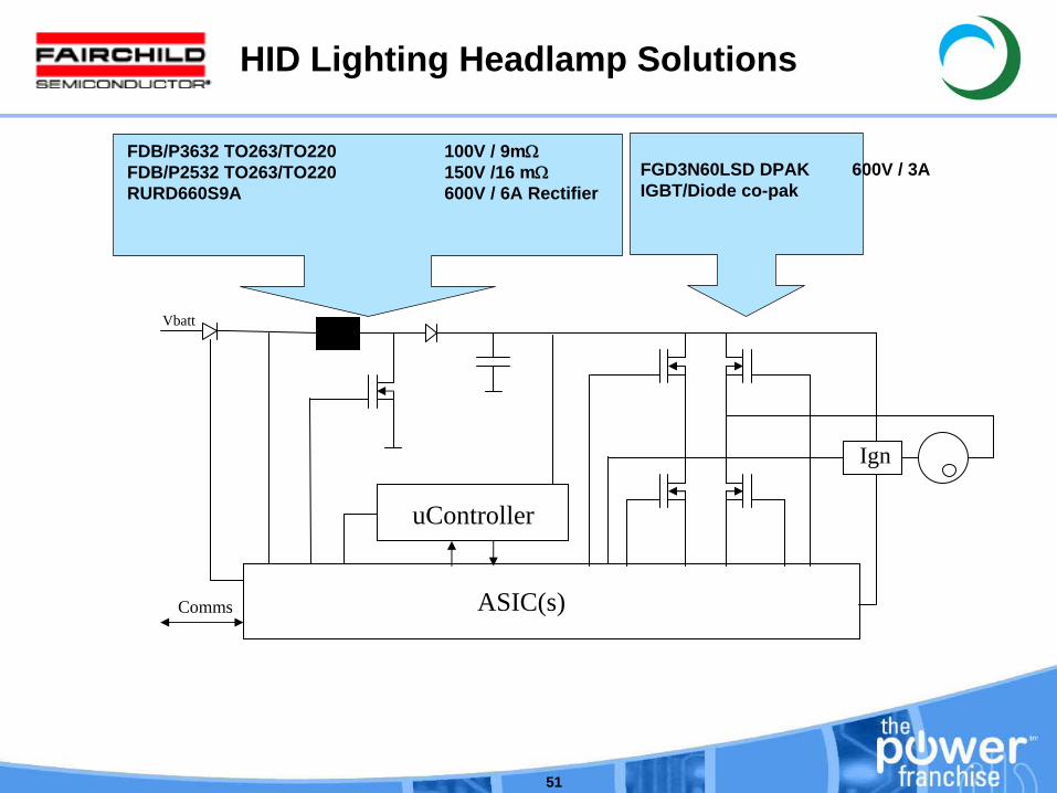
HID Lighting Headlamp Solutions
Ign
Vbatt
uController
Comms ASIC(s)
FGD3N60LSD DPAK 600V / 3A IGBT/Diode co-pak
FDB/P3632 TO263/TO220 100V / 9mΩFDB/P2532 TO263/TO220 150V /16 mΩRURD660S9A 600V / 6A Rectifier
52
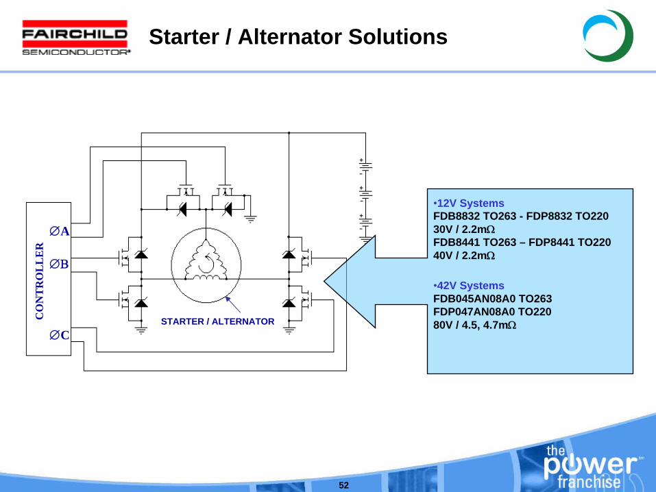
Starter / Alternator Solutions
∅A
∅Β
∅C
CO
NT
RO
LL
ER
STARTER / ALTERNATOR
•12V SystemsFDB8832 TO263 - FDP8832 TO220 30V / 2.2mΩ
FDB8441 TO263 – FDP8441 TO22040V / 2.2mΩ
•42V SystemsFDB045AN08A0 TO263FDP047AN08A0 TO220 80V / 4.5, 4.7mΩ

www.fairchildsemi.com
53
Automotive Power Modules

54
EPS/EHPS MODULES
BENEFITS
•
LOWER OVERALL ELECTRICAL RESISTANCE AND HIGHER CURRENT HANDLING•
INCREASED ELECTRONICS INTEGRATION (LOWER NUMBER OF COMPONENTS)•
COMPACTNESS•
BETTER EMI PERFORMANCE•
LOWER MOTOR RIPPLE•
EASIER AND QUICKER INSTALLATION•
EQUIVALENT/LOWER COST AT SYSTEM LEVEL
Full three phase inverter (6 Die + thermistor + current sense resistor + EMI components) in a foot print of6 D2Pack only
Full three phase inverter in a foot print of just 2 D2Pack
FOR CAR MANUFACTURERS MAXIMUM OUTPUT FORCE OR TORQUEIS ONE OF THE MOST IMPORTANT FACTORS AS COST
55
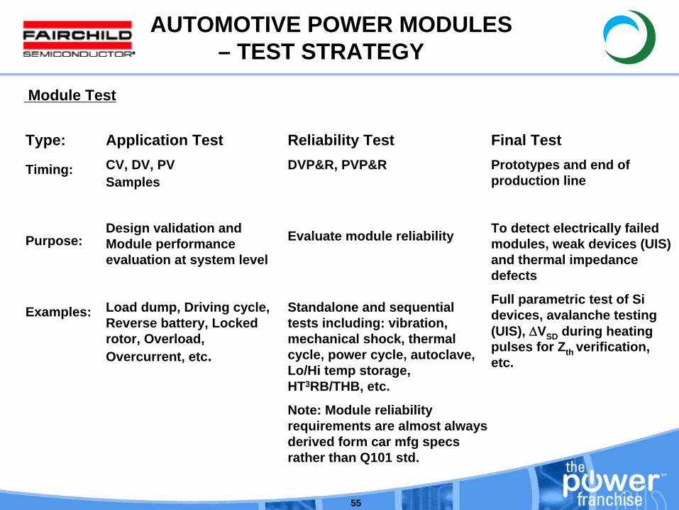
Module Test
AUTOMOTIVE POWER MODULES – TEST STRATEGY
Type:
Timing:
Purpose:
Examples:
Application TestCV, DV, PVSamples
Design validation and Module performance evaluation at system level
Load dump, Driving cycle, Reverse battery, Locked rotor, Overload, Overcurrent, etc.
Reliability TestDVP&R, PVP&R
Evaluate module reliability
Standalone and sequential tests including: vibration, mechanical shock, thermal cycle, power cycle, autoclave, Lo/Hi temp storage, HT3RB/THB, etc.
Note: Module reliability requirements are almost always derived form car mfg specs rather than Q101 std.
Final TestPrototypes and end of production line
To detect electrically failed modules, weak devices (UIS) and thermal impedance defects
Full parametric test of Si devices, avalanche testing (UIS), ΔVSD during heating pulses for Zth verification, etc.

www.fairchildsemi.com
56
Why Power Modules?

57
BASEPLATE TEMPERATURE
CURRENT NEEDS
COMPACTNESS NEEDS
DISCRETES OR MODULES
58
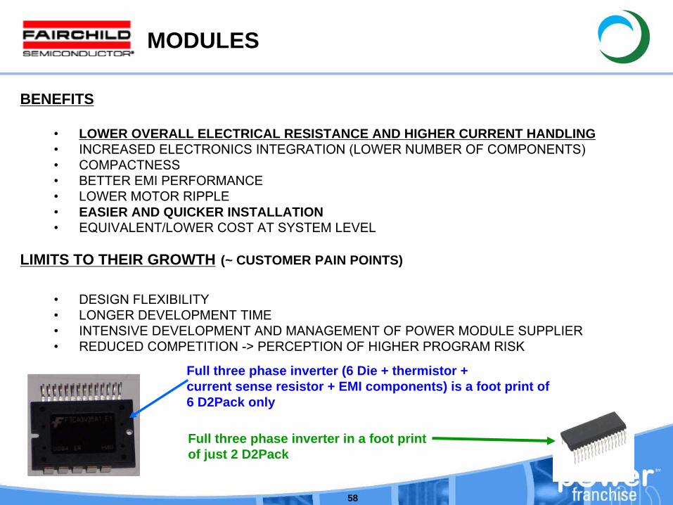
MODULES
BENEFITS
•
LOWER OVERALL ELECTRICAL RESISTANCE AND HIGHER CURRENT HANDLING•
INCREASED ELECTRONICS INTEGRATION (LOWER NUMBER OF COMPONENTS)•
COMPACTNESS•
BETTER EMI PERFORMANCE•
LOWER MOTOR RIPPLE•
EASIER AND QUICKER INSTALLATION•
EQUIVALENT/LOWER COST AT SYSTEM LEVEL
LIMITS TO THEIR GROWTH (~ CUSTOMER PAIN POINTS)
•
DESIGN FLEXIBILITY•
LONGER DEVELOPMENT TIME•
INTENSIVE DEVELOPMENT AND MANAGEMENT OF POWER MODULE SUPPLIER•
REDUCED COMPETITION -> PERCEPTION OF HIGHER PROGRAM RISK
Full three phase inverter (6 Die + thermistor + current sense resistor + EMI components) is a foot print of6 D2Pack only
Full three phase inverter in a foot print of just 2 D2Pack
59
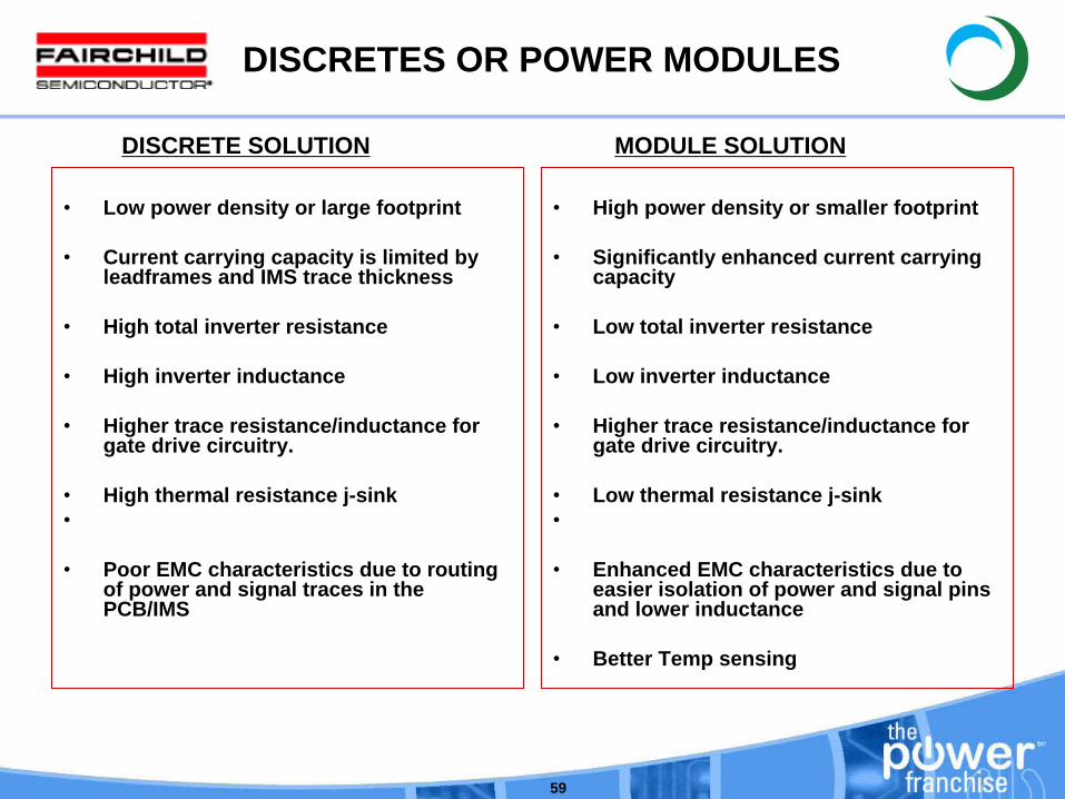
DISCRETES OR POWER MODULES
•
Low power density or large footprint
•
Current carrying capacity is limited by leadframes and IMS trace thickness
•
High total inverter resistance
•
High inverter inductance
•
Higher trace resistance/inductance for gate drive circuitry.
•
High thermal resistance j-sink •
•
Poor EMC characteristics due to routing of power and signal traces in the PCB/IMS
•
High power density or smaller footprint
•
Significantly enhanced current carrying capacity
•
Low total inverter resistance
•
Low inverter inductance
•
Higher trace resistance/inductance for gate drive circuitry.
•
Low thermal resistance j-sink•
•
Enhanced EMC characteristics due to easier isolation of power and signal pins and lower inductance
•
Better Temp sensing
DISCRETE SOLUTION MODULE SOLUTION
60
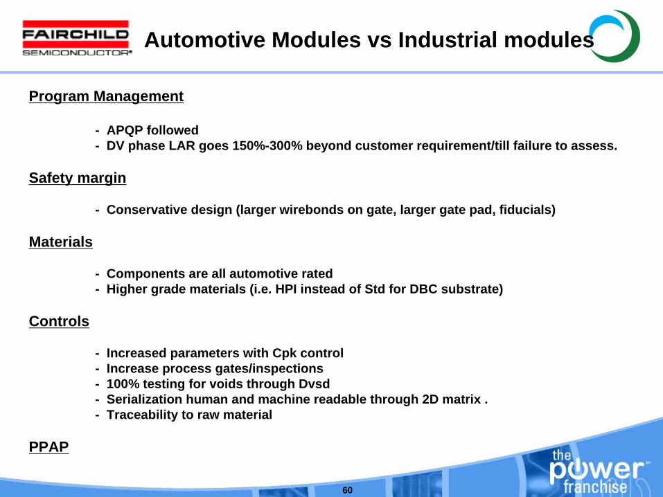
Automotive Modules vs Industrial modules
Program Management
- APQP followed - DV phase LAR goes 150%-300% beyond customer requirement/till failure to assess.
Safety margin
- Conservative design (larger wirebonds on gate, larger gate pad, fiducials)
Materials
- Components are all automotive rated - Higher grade materials (i.e. HPI instead of Std for DBC substrate)
Controls
- Increased parameters with Cpk control - Increase process gates/inspections - 100% testing for voids through Dvsd - Serialization human and machine readable through 2D matrix . - Traceability to raw material
PPAP

www.fairchildsemi.com
61
AEC Qualification and PPAP?
62
AEC
AEC ??Automotive Electronics Council in America.Europe companies have their own specific qualification procedures.
AEC-Q100For ICsNormally 6 months to take it.Requirements ;
Tri-temperature production testing if no failures after customer specified quantity.Full Testing on sampling from predetermined assembly lot sequence.AEC-Q101 qualification required for discrete power semiconductor portion of ASIC
AEC-Q101For discretesNormally 3 months to take it. Requirements ;
63
PPAP
PPAP ??Production Part Approval Process, required for each individual customer part type.Normally 2 ~ 3 months to get it.
Requirements•
Fairchild RequirementsDevices from 3 lots required.30 devices/lot, serialized (and saved) for static tri-temperature testing
(-40 / 25 / Tjmax).5 devices/lot for each human body and machine model (HB & MM) ESD tests.UIS Testing 3 devices/inductor x 3 lots x 2 temperatures x 3 – 4 inductors.
•
Customer RequirementsMust fill out a Fairchild PPAP Check list. (It is a cooperative undertaking.)May have additional requirements.

64www.fairchildsemi.com