Embed Size (px)
Citation preview

POWER SET BRAKE
Installation & Maintenance Manual
PE 13” THRU 30”
WPT Power Corporation
1600 Fisher Road - Wichita Falls, TX 76305
P.O. Box 8148 - Wichita Falls, TX 76307 Ph. 940-761-1971
www.WPTpower.com

Page 2 of 35 WIM-PE-000_A
Contents
1. Cautions and Warnings ............................................................................................................ 4
2. Introduction ............................................................................................................................. 5
2.1. Using this Manual ............................................................................................................. 5
2.2. Conditions of Use ............................................................................................................. 6
2.3. Product Descriptions ........................................................................................................ 6
2.4. Power Set Part Descriptions ............................................................................................. 8
3. Installation ............................................................................................................................. 11
3.1. Preparation and Alignment ............................................................................................ 11
3.2. Installation of Hub .......................................................................................................... 14
3.3. Installation of Brake ....................................................................................................... 14
3.4. Air System ....................................................................................................................... 16
3.5. Brake Release Test ......................................................................................................... 17
3.6. Burnishing ....................................................................................................................... 17
4. Operation ............................................................................................................................... 19
4.1. Pressure and Speed Limits ............................................................................................. 20
4.2. Operational Sequence .................................................................................................... 20
5. Disassembly ........................................................................................................................... 21
5.1. Complete Brake Removal ............................................................................................... 21
5.2. Disassembly for Brake Disc Replacement Only .............................................................. 21
5.3. Disassembly for O-ring Replacement ............................................................................. 22
5.4. Shim Removal ................................................................................................................. 23
5.5. Disassembly of Actuator Assembly ................................................................................ 24

Page 3 of 35 WIM-PE-000_A
6. Assembly ................................................................................................................................ 25
6.1. Assembly Instructions .................................................................................................... 25
6.2. Horizontal Mount Assembly ........................................................................................... 26
6.3. Vertical Mount Assembly ............................................................................................... 28
6.4. Basic Assembly ............................................................................................................... 29
7. Maintenance .......................................................................................................................... 30
7.1. Checking Operating Stroke ............................................................................................. 30
7.2. Adjusting Operating Stroke ............................................................................................ 31
7.3. Checking O-Ring Seals .................................................................................................... 31
8. Troubleshooting Guide .......................................................................................................... 32
9. General Storage Guidelines ................................................................................................... 33
10. Appendix ............................................................................................................................ 34

Page 4 of 35 WIM-PE-000_A
1. Cautions and Warnings
This manual contains several HAZARD WARNINGS that must be read and adhered to in order
to prevent possible loss of equipment and/or personal injury and /or loss of life. The three
warning words are “Danger”, “Warning”, and “Caution”. They are used to indicate severity of the hazard and may be preceded by a safety alert symbol.
............”DANGER” Denotes the most serious injury hazard and is used
when serious injury or death WILL result from misuse or failure to follow specific
instructions set forth in this manual.
............”WARNING” Denotes when serious injury or death MAY result
from misuse or failure to follow specific instructions set forth in this manual.
............”CAUTION” Denotes when injury or equipment damage may
result from misuse or failure to follow specific instructions set forth in this manual.
It is the responsibility of personnel involved in the installation, operation, and maintenance
of this equipment to fully understand hazards and correct procedures to safely install,
operate, and maintain this equipment.

Page 5 of 35 WIM-PE-000_A
2. Introduction
............DANGER
Forward this manual to person or persons responsible for installation and/or operation
and/or maintenance of the product described herein. Faulty installation, operation
and/or maintenance may occur without access to this information. Equipment damage,
personal injury, and even death may result.
............DANGER
Read these instructions thoroughly and review until you fully understand all warnings
and hazards before proceeding with the work described in this manual. Failure to follow
instructions in this manual can result in unreasonable exposure to hazardous conditions
and/or personal injury and/or death.
............DANGER
Use of improper tools and/or methods when installing or servicing this unit can result in
accidents causing injury and/or death. Adequate lifting points are provided to safely
handle individual unit components only. Lifting and handling of assembly will require use
of alternate methods.
............ CAUTION
Minimum personal protective equipment required for this procedure are: Safety glasses,
steel toe shoes. Always observe company policies above and beyond minimum required
for this procedure.
2.1. Using this Manual
Read these instructions before proceeding.
Diagrams and instructions in this manual are provided as a general guide for the field
repairman servicing the WPT brake. Diagrams are not intended to cover all models of brakes
but to provide general information.
NOTE: The drawing and bill of materials supplied with brake override information in this
manual.
When ordering replacement parts, use part numbers from bill of materials and drawing
supplied with brake. If these documents are lost, free replacements may be obtained by

Page 6 of 35 WIM-PE-000_A
contacting WPT or their distributor. Provide assembly number and serial number for unit
found on tag affixed to brake.
This manual utilizes English units with metric units shown in [brackets].
2.2. Conditions of Use
............DANGER
Equipment must be provided with pressure sensitive valve which will prevent application
of air to brake until “MINIMUM SUPPLY PRESSURE” is available. “MINIMUM SUPPLY PRESSURE” can be found on associated assembly drawing. Failure to do so may result in
risk of ignition due to excessively hot parts.
............DANGER
Equipment must be provided with clean instrument air or sufficient filter device with
proper maintenance to ensure air introduced to system is dry and free of contaminants.
............DANGER
Protective means must be used to prevent oil, grease, and/or dirt from contacting
surfaces of frictions or wear surfaces. Oil and/or grease will significantly reduce torque
capacity of the unit. Dirt may produce erratic torque. Suggested IP 54 protection level.
2.3. Product Descriptions
The WPT Power-Set Brake is a spring set, pneumatic release disc brake. Spring force acts on
the pressure plate to press wear plates to the drive discs. Air is applied to the piston/cylinder
air chamber to raise piston and pressure plate against spring force to release brake discs.
WPT units are available in various sizes, quantities of brake discs, and configuration. Consider
for example, a “325 POWER SET” indicates there are three 25” diameter brake discs. Vertical
mounted units are designed for applications with a vertical shaft. Horizontal mount units are
designed for applications with a horizontal shaft.
Unit must have hub attached to shaft of the equipment being managed. Also, housing of the
brake must be attached to either the equipment being managed or by a rigid support
member.

Page 7 of 35 WIM-PE-000_A
Unit is in an engaged state when actuator is not pressurized. Applying pressure to piston
works against engagement spring to release brake discs allowing hub to turn. Release springs
in some units ensure release of all brake discs from the wear surfaces.
Path of torque passes through the unit from the equipment’s shaft, through the hub, through
the brake discs, to the wear plates into studs and drive ring.
When ordering replacement parts, use part numbers from bill of materials and drawing
supplied with unit. Current documents may be obtained by contacting WPT or an authorized
distributor. Provide assembly number and serial number for unit found on brass tag affixed
to front of the unit. See Example in Figure 1.
Figure 1 Example Brass Tag
Recommended spare parts should be held by customer. This will greatly reduce possibility of
costly downtime.
xxx-xx-xxx
x xxxxxx

Page 8 of 35 WIM-PE-000_A
2.4. Power Set Part Descriptions
Table 1 Part Nomenclature
1 Hex head Cap Screw 10 Washer 19 Center Wear Plate Ass’y
2 Lock washer 11 Cylinder 20 Release Spring Shim
3 Cover Plate 12 Plug 21 Inner Brake Disc Ass’y
4 Socket Head Cap Screw 13 Shim 22 Release Spring Shim
5 Piston 14 Engagement Spring 23 Inner Wear Plate
6 Dust Seal 15 Insulating Washer 24 Hub
7 O-ring 16 Pressure Plate 25 Drive Ring Ass’y
8 O-ring 17 Outer Wear Plate Ass’y
9 Nut 18 Outer Brake Disc Ass’y
Figure 2 Exploded View

Page 9 of 35 WIM-PE-000_A
Figure 3 Section view of W25-PE-206

Page 10 of 35 WIM-PE-000_A
Figure 4 Example Release Spring Assembly
Table 2 Part Nomenclature-Release Spring
1 Set Screw
2 Release Spring Pin
3 Release Spring Collar
4 Release Spring
5 Insulating Washer

Page 11 of 35 WIM-PE-000_A
3. Installation
............DANGER
Use only proper quantity and grade of fasteners shown in drawings. Failure to do so may
result in fastener failure and/or a reduction in unit torque.
............CAUTION
Follow safety guidelines utilizing lockout tagout procedures before and during all
installation and maintenance procedures.
............CAUTION
Remove or block loads held by brake before performing any service. Failure to do so may
result in grave bodily harm.
............CAUTION
Even though units are properly set before shipment from factory, they should be checked
for proper clearance before being put into operation. See Section 7.1 for detailed
instruction on checking clearance.
3.1. Preparation and Alignment
............CAUTION
Proper alignment is necessary to ensure drive discs track properly. Improper alignment
will result in excessive wear to friction material and mating surfaces and generate heat
and excessive drag. Improper alignment will also overstress gear and splined bore of drive
discs. See Figure 5.

Page 12 of 35 WIM-PE-000_A
Figure 5 Drive Disc Alignment
Refer to appropriate assembly drawing (available upon request) for envelope dimensions,
mounting register diameters, and mounting bolt circles and positions for each brake.
The brake reaction member (such as the machine frame) should have a machined register
to allow for the mounting and alignment control of the brake. The mounting surface should
be designed to provide full support of the face of the mounting flange in order to prevent
any deflection during operation.
For proper operation and service life, the brake’s drive ring must be concentric with and
aligned to shaft within limits shows in Table 3.
Table 3 Alignment Requirements
BRAKE SIZE CONCENTRICITY PERPENDICULARARITY
13” 0.0065” (0.165) 0.0065” (0.165)
17” 0.0085” (0.216) 0.0085” (0.216)
21” 0.0110” (0.279) 0.0110” (0.279)
25” 0.0125” (0.318) 0.0125” (0.318)
30” 0.0150” (0.381) 0.0150” (0.381)

Page 13 of 35 WIM-PE-000_A
IMPORTANT:
Refer to appropriate assembly drawing for setup dimensions between brake mounting
surface and end of hub. The hub should be positioned to ensure disc splines will not
overhang end of hub when brake is mounted. Brake hub should be checked for overhang
with new and worn conditions.
Concentricity of the Shaft: With dial indicator mounted to a solid part of machine, place
indicator tip on shaft and rotate shaft. Total Indicated Reading should have a maximum value
shown in Table 3. See Figure 6 below.
Figure 6 Measuring Concentricity of the Shaft
Concentricity of Pilot: With dial indicator mounted to the shaft, place indicator tip on pilot
diameter and rotate shaft. Total Indicated Reading should have a maximum value shown in
Table 3. See Figure 7 below.
Figure 7 Measuring Concentricity of the Pilot
Perpendicularity of the Mounting Face: With dial indicator mounted to shaft, place indicator
tip on face of mounting surface and rotate shaft. Total Indicated Reading should have a
maximum value shown in Table 3. See Figure 8.

Page 14 of 35 WIM-PE-000_A
Figure 8 Measuring Perpendicularity of the Mounting Face
3.2. Installation of Hub
3.2.1. Check that equipment shaft equipment is free of nicks and burrs. Check
concentricity of the shaft. Ensure key will fit properly in shaft and hub.
3.2.2. If brake is to be mounted while completely assembled, be sure disc splines are
aligned with each other and hub splines. This is accomplished by installing hub
in discs to align splines. Apply enough air pressure to unit to release discs.
Center hub and discs in brake and release air pressure to engage drive plates.
3.2.3. For a straight or splined hub, heat hub uniformly to 250° F (121° C) to expand
bore and ease assembly. Press hub onto shaft, making sure dimension between
hub and unit mounting surface is maintained. Distance is found on unit
assembly drawing. Allow hub to cool.
3.2.4. For a tapered bore hub, tighten nut per machine manufacturer’s guidelines.
3.2.5. Ensure hub is properly positioned on shaft in relation to unit. Hub should be
locked in this position to prevent axial movement during installation.
3.2.6. Perpendicularity of Hub: With a dial indicator mounted to a solid part of
machine, place indicator tip on face of hub and rotate shaft. Verify hub face is
perpendicular to shaft with maximum Total Indicated Reading shown in Table
3.
3.3. Installation of Brake
............CAUTION
Maximum allowable air pressure is 130 lbf/in² [9 bar]. Application of air pressure
exceeding maximum allowable may result in damage to brake.

Page 15 of 35 WIM-PE-000_A
3.3.1. Ensure equipment mounting surface is clean and free of nicks and burrs. Install
adapter plate as required.
3.3.2. Clean hub spline of dirt and lightly coat with MoS2 dry film lubricant or
equivalent.
3.3.3. Use proper lifting equipment to lift brake and slide it over hub.
3.3.4. Position brake in corresponding pilot. Mounting should be a slip fit. If binding
occurs, remove brake and check for burrs.
3.3.5. Use customer supplied bolts to fasten brake to frame. Tighten to recommended
torque see Table 5.
3.3.6. Attach air equipment as specified in Section 3.4.
3.3.7. Even though brake is properly set before shipment from factory, it should be
checked for proper clearance before being put into operation. Operating
clearance is obtained by measuring axial distance (stroke) moved by piston
relative to cylinder or other stationary location on brake. See Section 7.1 for
procedure to check stroke.
3.3.8. Clearance should be as indicated on assembly drawing for the specific brake.
3.3.9. If installing a brake mounted on a vertical shaft, additional shimming may be
required between drive ring and equipment mounting surface.
3.3.10. Apply at least minimum release pressure noted on assembly drawing up to 130
lbf/in² [9 bar].
3.3.11. If dimensions shown in Figure 9 are present on assembly drawing, measure “X” and “Y” distances on inner and outer side of friction pucks to adjacent wear surface.

Page 16 of 35 WIM-PE-000_A
3.3.12. Customer is to provide shims to install between drive ring mounting surface and
adjacent equipment or adapter mounting surface to obtain clearance values
listed on assembly drawings.
3.4. Air System
3.4.1. Maximum allowable pressure is 130 lbf/in² [9 bar] for the brake.
3.4.2. Use only clean, filtered air (50 micron filter or better is recommended). Air
should be free of excess moisture especially when temperatures could approach
freezing.
3.4.3. Air inlets are located in the cylinder. The lowest port should be at or near the 6
o’ clock position to facilitate purging of any moisture that may accumulate in air
system. If only one inlet is being used, connection must be made at lowest
position possible.
3.4.4. All pipes should be free of metal chips, cutting compound, and any other foreign
matter. Pipe ends should be reamed after cutting to eliminate any possible
restrictions or burrs. For optimum air system response, a minimum number of
bend and elbows should be used.
3.4.5. Final connection to brake’s inlet ports can be made using flexible or rigid
hoses/tubing. If only one inlet is being used, connection must be made at lowest
position possible.
Figure 9 Vertical Mount Clearance Locations

Page 17 of 35 WIM-PE-000_A
3.5. Brake Release Test
3.5.1. Visually inspect all mounting bolts and fittings for tightness.
3.5.2. Apply at least minimum release pressure noted on the assembly drawing up to
130 lbf/in² [9 bar].
3.5.3. Manually cycle brake by applying and releasing air pressure. Piston should slide
in and out of the cylinder quickly and smoothly.
3.6. Burnishing
............Warning
Sparks may occur during this procedure. Ensure all flammable materials are removed
from area.
............CAUTION
Minimum personal protective equipment required for this procedure are: Safety glasses,
fire retardant clothing, steel toe shoes, and hard hat. Always observe company policies
above and beyond minimum required for this procedure
Burnishing is the process of controlled wear to the friction surfaces prior to operational
use. Burnish-in procedure should be performed on all new and relined discs. The process
works to create maximum surface area and establishes the designed coefficient of friction.
3.6.1. Install brake according to sections 3.1, 3.2, 3.3, and 3.4.
3.6.2. Check operating clearance conforms to requirements listed on appropriate
assembly drawing.
3.6.3. Check and record initial temperature of pressure plate using a handheld infrared
temperature sensor. If a temperature sensor is installed on brake, do not
perform test until monitor reads that engagement is allowed.
3.6.4. During process if temperature exceeds 300°F (149°C), stop procedure and allow
to cool down below 200°F (93°C). Some sparking may occur and disc particles
may be ejected from brake. Excessive amounts of either could indicate a
problem such as overheating or improper release. Stop and correct if this
occurs.

Page 18 of 35 WIM-PE-000_A
3.6.5. Remove excess load on machine, perform (4) four stops at (¼) one-quarter
speed. Allow at least (1) one minute between stops and ensure brake
temperature is below 200°F (93°C).
3.6.6. Remove excess load on machine, perform (8) eight stops at (½) one-half speed.
Allow at least (2) Two minutes between stops and ensure brake temperature is
below 200°F (93°C).
3.6.7. Check static holding torque of brake at maximum load with motor stopped. If
unit does not hold load, repeat burnish in procedure and recheck static holding
torque.
3.6.8. On hoist, drag, and propel brake units, perform (1) one additional full load/full
speed stop to be certain unit is stopping within manufacturer’s guidelines for stopping distances and times.
3.6.9. On swing brake units, perform (1) one additional full load/ ¾ speed stop to be
certain stopping angles and times are within manufacturer’s guidelines.

Page 19 of 35 WIM-PE-000_A
4. Operation
............DANGER
This is a parking brake. It can be used in an emergency. It will overheat and could ignite
explosive gas if used as a dynamic brake.
............DANGER
Do not exceed maximum surface temperature 300°F (149°C). Exceeding maximum
temperature could ignite explosive gas.
............Warning
For ambient temperature below -4°F (-20°C), warm brake to -4°F (-20°C) before heavy use.
Failure to warm brake may result in damage to components.
............Warning
Maximum speed must not exceed speeds listed in Table 4. Exposure to speeds in excess of
these values may cause friction discs to spark and result in extensive damage to brake and/or
personal injury.
............Warning
Protective means must be used to prevent oil, grease, and/or dirt from contacting surfaces
of friction disc, or wear surfaces. Oil and /or grease on these parts will significantly reduce
torque capacity of unit. Dirt will produce erratic torque. Do not risk personal injury or damage
to equipment.
Page 20 of 35 WIM-PE-000_A
4.1. Pressure and Speed Limits
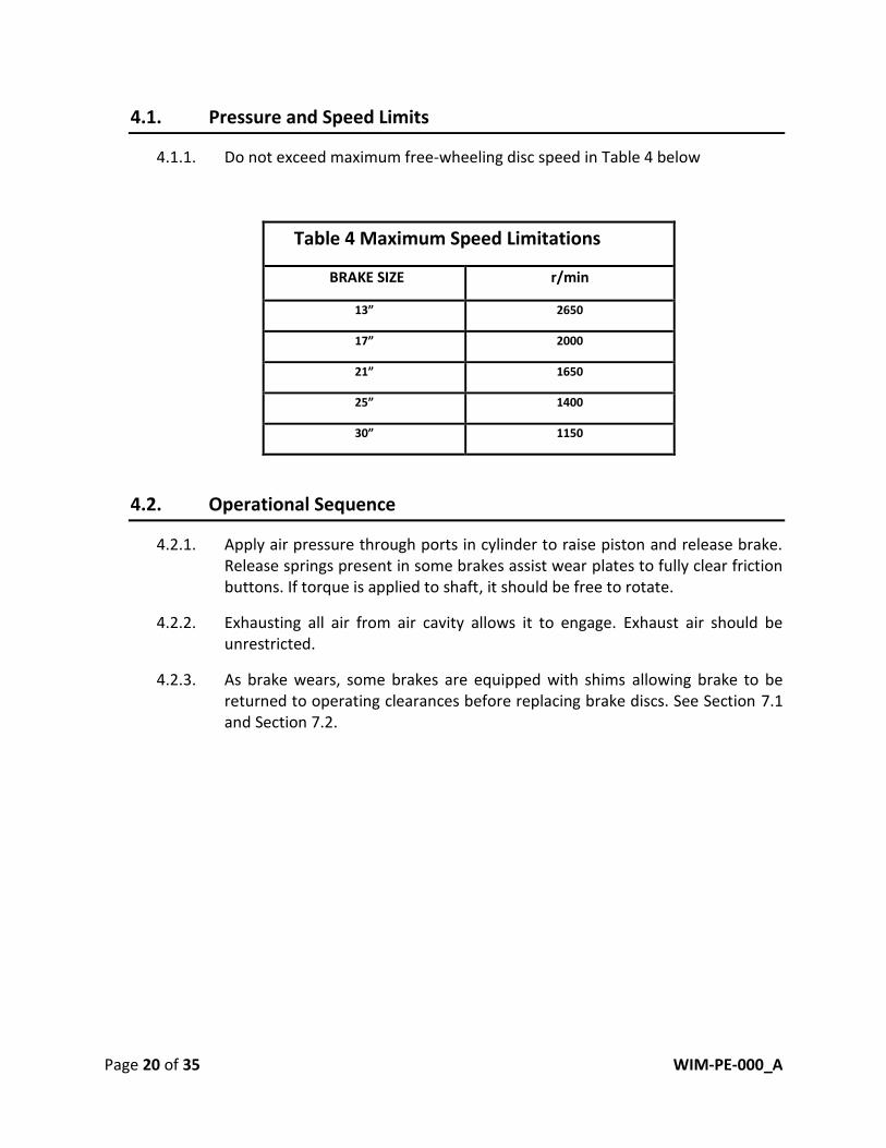
4.1.1. Do not exceed maximum free-wheeling disc speed in Table 4 below
Table 4 Maximum Speed Limitations
BRAKE SIZE r/min
13” 2650
17” 2000
21” 1650
25” 1400
30” 1150
4.2. Operational Sequence
4.2.1. Apply air pressure through ports in cylinder to raise piston and release brake.
Release springs present in some brakes assist wear plates to fully clear friction
buttons. If torque is applied to shaft, it should be free to rotate.
4.2.2. Exhausting all air from air cavity allows it to engage. Exhaust air should be
unrestricted.
4.2.3. As brake wears, some brakes are equipped with shims allowing brake to be
returned to operating clearances before replacing brake discs. See Section 7.1
and Section 7.2.

Page 21 of 35 WIM-PE-000_A
5. Disassembly
............Warning
Only qualified personnel should install, adjust and/or repair WPT brake. Faulty workmanship
could result in faulty installation, dangerous operation of brake, repeated costly
maintenance and greatly shorten life of brake.
............Warning
Ensure machinery is and will remain in a locked and safe position prior to loosening fasteners
or removing brake.
............Warning
Use caution when removing brake bolts. Springs within brake store energy and could cause
the brake to fly apart.
5.1. Complete Brake Removal
5.1.1. Remove all hose connections.
5.1.2. Remove any auxiliary measurement devices from brake.
5.1.3. Use appropriate lifting equipment to support weight of brake.
5.1.4. Evenly remove bolts securing drive ring to equipment mounting surface.
5.1.5. Slide brake from hub.If binding occurs, air pressure can be applied to release
brake discs.
5.2. Disassembly for Brake Disc Replacement Only
............DANGER
Do not remove socket head sap screws connecting piston to pressure plate. Bolts are not
long enough to remove all spring pressure when drive stud nuts are removed. See Section
5.5 for disassembly of actuator assembly.

Page 22 of 35 WIM-PE-000_A
5.2.1. Inspect exposed threads of drive studs. Galling may occur during removal if
threads are damage. Correct before moving to next step.
5.2.2. Apply air pressure to actuator to release brake. This compresses springs so stud
nuts do not have pressure on them. Studs are not long enough to remove spring
pressure without releasing brake.
5.2.3. Once nuts are removed, release air pressure slowly and use proper lifting
equipment to remove entire piston/cylinder/pressure plate assembly and set
aside.
5.2.4. Remove extra wear plates, if present, to access drive discs for replacement.
5.2.5. With new or relined drive discs installed on hub, reassemble plates checking
assembly drawing for appropriate alignment.
5.2.6. Reposition piston/cylinder/pressure plate assembly on studs.
5.2.7. Install shims as required by assembly drawing for new friction discs.
5.2.8. Apply air pressure to piston/cylinder and install nuts slowly and evenly in a star
pattern. Torque to value listed on assembly drawing or Table 5.
5.3. Disassembly for O-ring Replacement
............DANGER
Do not remove drive stud nuts connecting cylinder to drive ring. Drive studs are not long
enough to remove all spring pressure. To remove nuts, ensure piston and socket head cap
screws are installed and see Section 5.5 for disassembly of actuator assembly.
5.3.1. Remove all hose connections.
5.3.2. Ensure brake is engaged and no air pressure is applied.
5.3.3. Slowly and evenly remove socket head cap screws connecting piston to pressure
plate. DO NOT remove stud nuts with piston screws removed.
5.3.4. Remove piston from cylinder.
5.3.5. Replace O-rings in piston, applying Chevron Moly grease NLGI 2, or equal, to
new O-rings.

Page 23 of 35 WIM-PE-000_A
5.3.6. Reinsert piston in cylinder. Appropriately sized all-thread can be used to align
bolt holes.
5.3.7. Evenly install socket head cap screws. Torque to value listed in assembly
drawing or Table 5.
5.3.8. Burnish all new and relined discs according to Section 3.6.
5.4. Shim Removal
............DANGER
Do not remove socket head sap screws connecting piston to pressure plate. Bolts are not
long enough to remove all spring pressure when drive stud nuts are removed. See Section
5.5 for disassembly of actuator assembly.
5.4.1. See Section 7.2 for appropriate instruction to determine if shim(s) should be
removed.
5.4.2. Inspect exposed threads of drive studs. Galling may occur during removal if
threads are damage. Correct before moving to next step.
5.4.3. DO NOT remove socket head cap screws connecting piston to pressure plate.
5.4.4. Apply air pressure to actuator to release brake. This compresses springs so stud
nuts do not have pressure on them.
5.4.5. If air pressure is not applied, slowly and evenly loosen nuts only until shims are
free.
5.4.6. Shims are designed with a split, so nuts do not need to be completely removed.
5.4.7. After shim is removed, tighten nuts to torque value listed on assembly drawing
or Table 5.
5.4.8. Check all clearances conform to values listed on assembly drawing. See Section
7.1 for instruction to check clearance.

Page 24 of 35 WIM-PE-000_A
5.5. Disassembly of Actuator Assembly
............Warning
Use caution when removing brake bolts. Springs within brake store energy and could cause
brake to fly apart.
Disassembly of actuator may be done using a combination of all-thread, washers, and nuts.
All-thread should match thread of socket head cap screws to screw into pressure plate.
Hardware should be grade 8 or better. All-thread length should be at least 6.0” [152]
above piston.
5.5.1. Remove half of the socket head cap screws.
5.5.2. Thread all-thread in spring plate and add washer to top of piston.
5.5.3. Thread nuts on all-thread and hand tighten to piston.
5.5.4. Slowly and evenly remove remaining socket head cap screws. Spring force is
held by temporary nuts on all-thread.
5.5.5. Slowly and evenly loosen nuts to release spring force. If all-thread begins to
unthread in pressure plate, measures should be taken to secure all-thread
while nuts are loosened.
5.5.6. Once all spring force is removed, remove all-thread and lift piston out of
cylinder.
Page 25 of 35 WIM-PE-000_A
6. Assembly
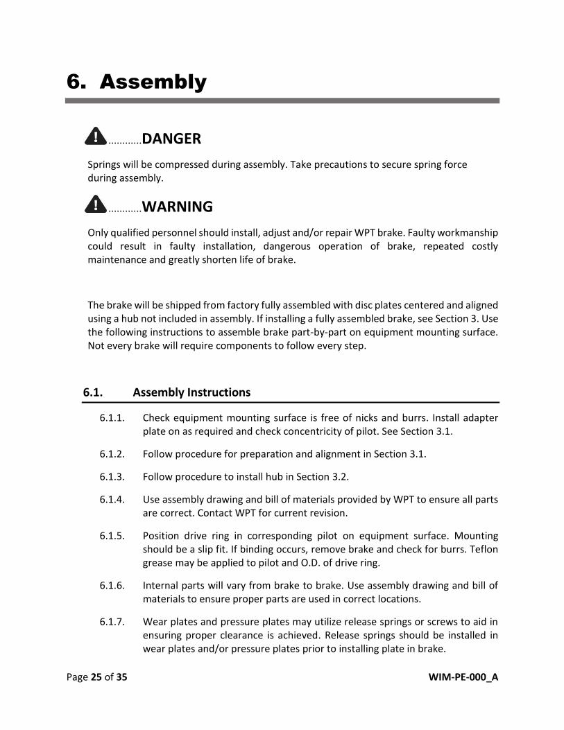
............DANGER
Springs will be compressed during assembly. Take precautions to secure spring force
during assembly.
............WARNING
Only qualified personnel should install, adjust and/or repair WPT brake. Faulty workmanship
could result in faulty installation, dangerous operation of brake, repeated costly
maintenance and greatly shorten life of brake.
The brake will be shipped from factory fully assembled with disc plates centered and aligned
using a hub not included in assembly. If installing a fully assembled brake, see Section 3. Use
the following instructions to assemble brake part-by-part on equipment mounting surface.
Not every brake will require components to follow every step.
6.1. Assembly Instructions
6.1.1. Check equipment mounting surface is free of nicks and burrs. Install adapter
plate on as required and check concentricity of pilot. See Section 3.1.
6.1.2. Follow procedure for preparation and alignment in Section 3.1.
6.1.3. Follow procedure to install hub in Section 3.2.
6.1.4. Use assembly drawing and bill of materials provided by WPT to ensure all parts
are correct. Contact WPT for current revision.
6.1.5. Position drive ring in corresponding pilot on equipment surface. Mounting
should be a slip fit. If binding occurs, remove brake and check for burrs. Teflon
grease may be applied to pilot and O.D. of drive ring.
6.1.6. Internal parts will vary from brake to brake. Use assembly drawing and bill of
materials to ensure proper parts are used in correct locations.
6.1.7. Wear plates and pressure plates may utilize release springs or screws to aid in
ensuring proper clearance is achieved. Release springs should be installed in
wear plates and/or pressure plates prior to installing plate in brake.

Page 26 of 35 WIM-PE-000_A
6.1.8. Clean hub spline of dirt, lightly coat with MoS2 dry film lubricant or equivalent.
6.1.9. If present, install inner wear plate. Ensure holes and spring pockets are oriented
correctly.
6.1.10. If applicable, use proper shoulder bolt or socket head cap screw in bill of
materials to secure inner wear plate to drive ring. Use lubrication as required by
assembly drawing and torque to value listed on assembly drawing. Torques
listed on assembly drawing take precedence if noted.
6.1.11. Slide drive discs on hub to contact inner wear surface. Ensure proper orientation
if required. For discs with release springs, ensure pins align in corresponding
locations.
6.1.12. For multiple disc units, install center plate with release springs previously
installed. Check spring pin collars are properly seated in corresponding pocket
in adjacent wear plate. Subsequent levels of release spring pins should align
with previous row.
6.1.13. Repeat step 6.1.12 as required.
6.1.14. For horizontal mount assembly see Section 6.2.
6.1.15. For vertical mount assembly see Section 6.3.
6.2. Horizontal Mount Assembly
Brakes mounted horizontally should be assembled part-by-part separate from mounting
surface. If this installation method is acceptable follow procedure in Section 6.4 and install
complete brake according to procedure in Section 3.3. If brake must be installed part-by-
part on mounting surface see the following procedure.
6.2.1. Follow procedure for beginning stages of installation in Section 6.1.
6.2.2. The actuator of a unit for use with a horizontal shaft must be assembled
separately.
6.2.3. Set pressure plate on a flat surface and install release springs if required.
6.2.4. Place required number of engagement spring and insulating washers as
required in the bill of materials.
6.2.5. Position cylinder and check all springs are seated correctly in spring pockets.
6.2.6. Stud holes in pressure plate and cylinder should align. Spare drive studs may be
used to aid in aligning stud holes since misalignment may make installation of
actuator assembly difficult.

Page 27 of 35 WIM-PE-000_A
6.2.7. Install dust seal in piston trimming to length so the two ends meet. Cover
outside edge with Chevron Moly grease NLGI 2, or equivalent.
6.2.8. Cover O-rings with Chevron Moly grease NLGI 2, or equivalent, then install in
piston, taking care not to roll O-ring in groove.
6.2.9. Lightly coat sealing surfaces and air cavity in cylinder and piston with Chevron
Moly grease NLGI 2, or equivalent.
6.2.10. Screw all-thread into every other tapped hole in the spring plate. All-thread
should be at least grade 8 and long enough to extend at least 6 inches above
piston when it is lowered into place.
6.2.11. Lower piston in cylinder using all-thread to ensure bolt holes are aligned.
6.2.12. Add washers and nuts to all-thread. Tighten nuts to compress piston and spring
plate together.
6.2.13. Apply Chevron Moly grease NLGI 2 or equivalent to socket head cap screws and
install in remaining holes.
6.2.14. Remove all-thread (no tension should be on the all-thread)
6.2.15. Install socket head cap screws in remaining holes. Torque in a star pattern to
value required by assembly drawing or Table 5.
6.2.16. Using appropriate lifting equipment, install actuator assembly on drive ring
studs until cylinder pilot starts in drive ring.
6.2.17. Install shims if required over cylinder pilot to rest on the top of drive ring.
6.2.18. Apply air pressure to actuator.
6.2.19. Visually inspect threads on drive studs and correct if nicks are found. Apply
Chevron Moly grease NLGI 2 or equivalent to threads.
6.2.20. Install nuts evenly and torque in a star pattern. See assembly drawing for nut
torque or Table 5.
6.2.21. After brake is assembled refer to Section 3 for remaining installation
instructions.
Page 28 of 35 WIM-PE-000_A
6.3. Vertical Mount Assembly
The following procedure is for assembling brake part-for-part on mounting surface for a
vertically mounted brake.
6.3.1. Follow procedure for beginning stages of installation in Section 6.1.
6.3.2. Actuator assembly portion of unit should be installed part-by-part on drive
ring. If necessary, actuator assembly may be assembled separate and then
installed on drive studs. See Section 6.2 for instruction on how to assemble
actuator assembly separate from brake.
6.3.3. Install pressure plate in drive ring with release springs installed if required.
6.3.4. Place engagement spring and insulating washers as required in bill of materials.
6.3.5. Position cylinder in drive ring and check all springs are seated correctly in
spring pockets.
6.3.6. Install shims if required over cylinder pilot on top surface of drive ring.
6.3.7. Install dust seal in piston, trimming to length so the two ends meet. Cover
outside edge with Chevron Moly grease NLGI 2 or equivalent.
6.3.8. Cover O-rings with Chevron Moly grease NLGI 2 or equivalent and install in
piston taking care not to roll O-ring in groove.
6.3.9. Lightly coat sealing surfaces and air cavity in cylinder and piston.
6.3.10. Screw all-thread into every other tapped hole in the spring plate. All-thread
should be at least grade 8 and long enough to extend at least 6 inches above
piston when it is lowered into place.
6.3.11. Lower piston in cylinder using all-thread to ensure bolt holes are aligned.
6.3.12. Add washers and nuts to all-thread. Tighten nuts to compress piston and spring
plate together.
6.3.13. Apply Chevron Moly grease NLGI 2 or equivalent to socket head cap screws and
install in remaining holes.
6.3.14. Remove all-thread (no tension should be on the all-thread)
6.3.15. Install socket head cap screws in remaining holes. Torque in a star pattern to
value required by assembly drawing or Table 5.
6.3.16. Apply air pressure to actuator.

Page 29 of 35 WIM-PE-000_A
6.3.17. Visually inspect threads on drive studs and correct if damage is found. Apply
Chevron Moly grease NLGI 2 or equivalent to threads.
6.3.18. Install nuts evenly and torque in a star pattern. See assembly drawing for nut
torque or Table 5.
6.3.19. After brake is assembled refer to Section Installation3 for remaining installation
instructions
6.4. Basic Assembly
Basic assembly instructions should be used to assemble entire brake separate from
mounting surface.
6.4.1. Follow instructions for vertical mount assembly in Section 6.3, assembling unit
on a flat surface.
6.4.2. Use a loose hub to center and align disc splines.
6.4.3. If brake is to be installed, refer to Section 3.
6.4.4. If brake is to be stored, refer to Section 9.

Page 30 of 35 WIM-PE-000_A
7. Maintenance
............WARNING
Only qualified personnel should install, adjust, and/or repair the WPT brake. Faulty
workmanship could result in faulty installation, dangerous operation of brake, repeated
costly maintenance, and greatly shorten life of brake.
............WARNING
Ensure machinery is and will remain in a locked and safe position prior to loosening fasteners
or removing brake.
............WARNING
Failure to remove shims as required may deteriorate the brake torque to a point where
equipment will not be stopped.
............CAUTION
Periodically examine brake for wear of friction material and wear plates. Failure to perform
this examination periodically may result in excessive wear to components, improper
operation, or a significant reduction in torque and may result in personal injury and/or
damage to machinery.
7.1. Checking Operating Stroke
7.1.1. On all units, friction material must be replaced when maximum clearance has
been reached with all ring shims removed. See assembly drawing for maximum
and minimum clearance specifications.
7.1.2. Some unit designs allow for brake to return to its original operating clearances
by removing ring shims from brake. See Section 5.4 for shim removal.
7.1.3. Ensure brake is engaged with no air pressure applied.
7.1.4. Secure dial indicator to outside of drive ring with tip on a flat machined section
of piston.
Or secure dial indicator to flat section of piston with tip on a machined section of
the cylinder.

Page 31 of 35 WIM-PE-000_A
7.1.5. Record initial reading or zero indicator, ensuring enough travel remains on dial
indicator to measure entire movement.
7.1.6. Apply air pressure above release pressure noted on assembly drawing but
below 130 lbf/in² [9 bar].
7.1.7. Record final dial indicator reading.
7.1.8. The difference between the two measurements is total assembly clearance or
stroke of the piston.
7.2. Adjusting Operating Stroke
Many brakes include shims between top of drive ring and mating surface on cylinder. These
are to be removed when stroke of brake increases the amount of one shim. Removal of a
shims as frictions wear allows spring compression and in turn torque capacity to remain
consistent.
7.2.1. Follow Section 7.1 to measure brake stroke.
7.2.2. Compare worn stroke to new assembly stroke listed on assembly drawing or
original measured stroke if available.
7.2.3. Brake is worn if stroke is at or above maximum stroke listed on assembly
drawing.
7.2.4. If brake is worn and shims are present between drive ring and cylinder, one shim
may be removed to reduce stoke by thickness of the shim. See Section 5.4 for
shim removal procedure.
7.3. Checking O-Ring Seals
O-rings are pressure tested at factory for every new brake.
O-ring seals contain air within the chamber between piston and cylinder. O-ring
performance is influenced by several different factors. Inadequate pressure or loss in
pressure may indicate a failed O-ring. Apply at least minimum release pressure and hold for
10 minutes. Pressure loss should be no more than 10 lbf/in² [0.68 bar].
See Section 5.3 for instruction on disassembly for O-ring replacement.

Page 32 of 35 WIM-PE-000_A
8. Troubleshooting Guide
Problem Possible Cause Possible Remedy
Brake will not release
Tooth wear Replace hub and drive plates
Low operating
pressure
Verify operating pressure exceeds minimum operating
pressure and does not exceed 130 lbf/in² [9 bar]
Check for possible damage to hoses and/or actuator
Leaking seals Replace O-rings, look for and correct nicks or burrs which
may cut the O-ring
Jammed wear
plates Disassemble and inspect, replace parts as necessary
Torque below specification
Worn friction
surfaces
Check clearance and remove shims if necessary, according
to section 7.1 and 7.2.
If all shims are removed and clearance is above maximum
worn condition, replace or rebuild all drive discs.
Friction material
contamination
Thoroughly clean friction material-replace discs if
necessary
Damaged springs
In new brake, check number of springs matches bill of
material
Inspect springs for signs of wear-replace all springs if
necessary
Brake is getting too hot Brake is not
releasing See Troubleshooting “Brake will not release”

Page 33 of 35 WIM-PE-000_A
9. General Storage Guidelines
Upon receipt of parts or assemblies, they should be inspected for corrosion or other related
damage. If any problem is detected, contact WPT’s warranty department.
It is the owner’s primary responsibility to store and protect the WPT product.
Products should be stored in a manner protected from environment and outside sources,
which may include but are not limited to the following:
• Environmental storage requirements should be maintained as follows:
o No exposure to rainwater
o Temperatures 32F° (0C°) to 110F° (43C°)
o Below 50% average humidity
o Average sunlight
• Hazards requiring addition protection:
o Dust and debris
o Oil, water, saltwater, acids, or other chemicals
o Any other foreign items which may damage product
o Other measures include covering product to prevent ingress of foreign matter
• Additional Protection Measures for Long-Term Storage (Storage Exceeding 1 Month):
o Coating studs, hub, springs, and exposed metal with Cosmoline RP-342 "HEAVY"
Military-Grade Rust Preventive Aerosol Spray, or equal
o Coating of painted surfaces is not required or recommended
o Visually inspect product for degradation once every three-months

Page 34 of 35 WIM-PE-000_A
10. Appendix
Table 5 Stud Nut and Piston Bolt Torque
Size Stud Nut Torque
with Chevron Moly grease
NLGI 2, or equivalent
lbf·ft (N·m)
Piston Bolt Torque
with Chevron Moly grease
NLGI 2, or equivalent
lbf·ft (N·m)
13” 45-50 (61-67) 85-90 (115-122)
17” 70-80 (95-108) 50-55 (68-74)
21” 90-100 (122-135) 200-220 (272-298)
25” 110-120(150-162) 200-220(272-298)
30” 190-200 (257-271) 275-300 (373-406)
NOTE: Values for nut and bolt torque given on assembly drawing take precedence

Page 35 of 35 WIM-PE-000_A
This manual is property of WPT Power Corporation Wichita Falls, Texas and is
expressly intended for the propose of installing, operating and maintaining
equipment described in this manual. Any copying or any other use of this
manual other than what it was intended for is strictly prohibited.