Embed Size (px)
Citation preview

7 Best Practices to Prevent Damaging Power Meters and Power Sensors
David Haug
Marketing Development Manager
July 30, 2015
Sponsored by

Page
Agenda
– Why these practices are important?
– Best practices to prevent power meter/sensor damage Practice 1: Avoid overpower
Practice 2: Avoid overvoltage
Practice 3: Adhere to warnings and specifications
Practice 4: Protect RF connectors and adaptors
Practice 5: Ensure proper grounding
Practice 6: Take ESD precautions
Practice 7: Check for temperature and humidity
– Summary
– References
– Q&A
2 © Keysight Technologies 2015

Page
The Power Meter and Sensor Method
3
DC or low-frequency
equivalent RF power
Power Sensor Power Meter
Display
(dBm or W)
Thermistor Thermocouple Diode Detector
RF power
Power Sensor
Meter
Circuitry
Display
(dBm or W)
Thermistor Thermocouple Diode Detector
Integrated meter/sensor
USB
PC, FieldFox or other
© Keysight Technologies 2015

Page
Why these practices are important?
4
Quality??
Measurement Quality
Degradation
System Downtime Schedule Delay
Repair Cost
© Keysight Technologies 2015

Page
Practice 1: Avoid Overpower
Typical sensor max power: -20dBm, 20dBm, 30dBm, 35dBm, 44dBm
Have an idea of the signal level to be measured
Make sure expected measured power is within the dynamic range of the
sensor
Use a RF limiter to protect sensing element
5
Bulkhead housing the
sensing element
© Keysight Technologies 2015
Page
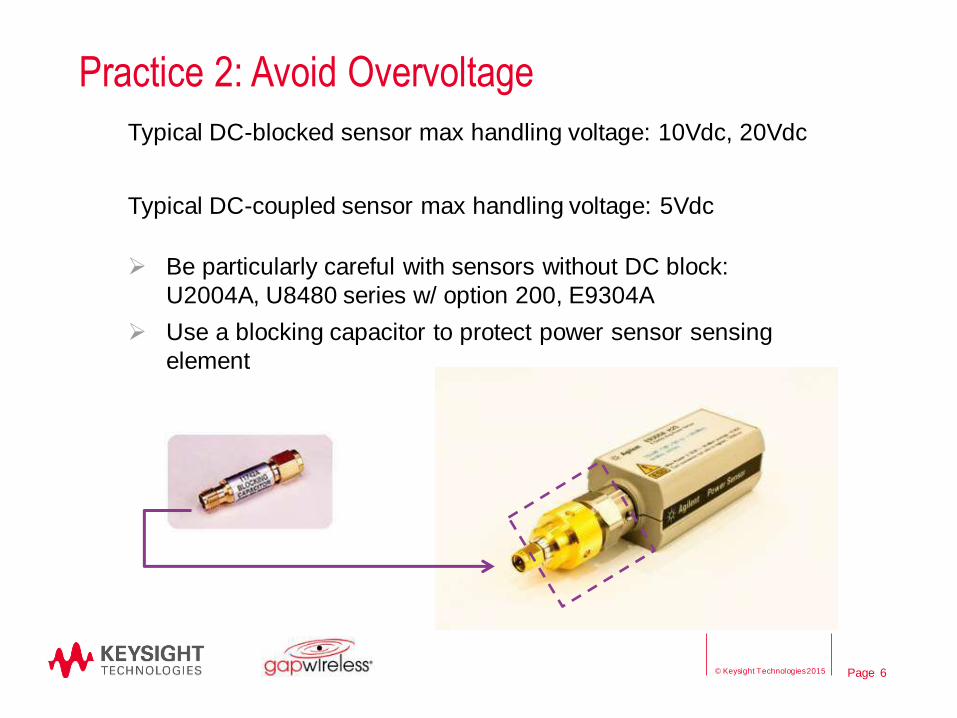
Practice 2: Avoid Overvoltage
Typical DC-blocked sensor max handling voltage: 10Vdc, 20Vdc
Typical DC-coupled sensor max handling voltage: 5Vdc
Be particularly careful with sensors without DC block:
U2004A, U8480 series w/ option 200, E9304A
Use a blocking capacitor to protect power sensor sensing
element
6 © Keysight Technologies 2015

Page
DC-blocked V.S. DC-coupled
DC-blocked power sensor
– A capacitor is placed serially in
front of sensing element
– Prevents DC leakage from entering
sensing element
– Good for measuring RF signals
with DC offset
DC-coupled power sensor
– Have slightly better VSWR
performance
– Good for operations at low
frequencies down to DC
7
Further reading:
http://literature.cdn.keysight.com/litweb/pdf/5990-6745EN.pdf
© Keysight
Technologies 2015

Page
Practice 3: Adhere to Warnings and Specifications
8
Frequency range Dynamic range
© Keysight Technologies 2015

Page
Select a Suitable Power Sensor
9
POWER METERS
Display Sequence 13 12 5 6 3 4 1 2 11 10 7 8 9
Model Number
432A
N432A
E4416A
EP
M-P
E4417A
EP
M-P
E4418B
EP
M
E4419B
EP
M
N1913A
EP
M
N1914A
EP
M
E1416A
VX
I
N8262A
P-S
eri
es
N1911A
P-S
eri
es
N1912A
P-S
eri
es
8990B
PP
A
N8480 / 8480 series
thermocouple & diode
sensors
N8481A
N8482A
N8485A
N8487A
N8488A
N8481B
N8482B
N8481H
N8482H
E9300 series average
sensors
E9300A
E9301A
E9304A
E9300B
E9301B
E9300H
E9301H
E9320 series peak &
average sensors
E9321A
E9322A
E9323A
E9325A
E9326A
E9327A
CW power sensor E4412A
E4413A
© Keysight Technologies 2015
Page
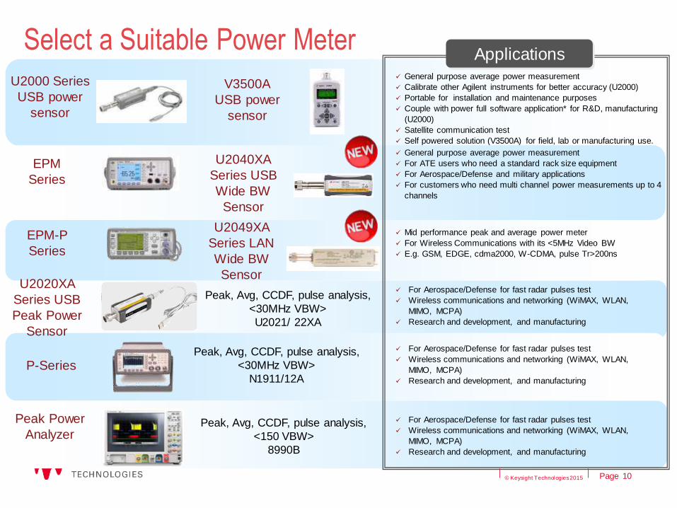
U2000 Series
USB power
sensor
General purpose average power measurement
Calibrate other Agilent instruments for better accuracy (U2000)
Portable for installation and maintenance purposes
Couple with power full software application* for R&D, manufacturing
(U2000)
Satellite communication test
Self powered solution (V3500A) for field, lab or manufacturing use.
EPM
Series
General purpose average power measurement
For ATE users who need a standard rack size equipment
For Aerospace/Defense and military applications
For customers who need multi channel power measurements up to 4
channels
EPM-P
Series
Mid performance peak and average power meter
For Wireless Communications with its <5MHz Video BW
E.g. GSM, EDGE, cdma2000, W-CDMA, pulse Tr>200ns
P-Series Peak, Avg, CCDF, pulse analysis,
<30MHz VBW>
N1911/12A
For Aerospace/Defense for fast radar pulses test
Wireless communications and networking (WiMAX, WLAN,
MIMO, MCPA)
Research and development, and manufacturing
Applications
V3500A
USB power
sensor
Select a Suitable Power Meter
10
Peak, Avg, CCDF, pulse analysis,
<150 VBW>
8990B
Peak Power
Analyzer
U2020XA
Series USB
Peak Power
Sensor
U2040XA
Series USB
Wide BW
Sensor
For Aerospace/Defense for fast radar pulses test
Wireless communications and networking (WiMAX, WLAN,
MIMO, MCPA)
Research and development, and manufacturing
U2049XA
Series LAN
Wide BW
Sensor
Peak, Avg, CCDF, pulse analysis,
<30MHz VBW>
U2021/ 22XA
For Aerospace/Defense for fast radar pulses test
Wireless communications and networking (WiMAX, WLAN,
MIMO, MCPA)
Research and development, and manufacturing
© Keysight Technologies 2015

Page
Practice 4: Protect RF Connectors and Adaptors
11
All RF connectors have a limited lifespan
Proper care and handling can maximize the lifespan of your connectors
A damaged or out-of-specification device can destroy another good
connector
Effects of a bad connector:
Mismatch
Measurement error
Repeatability problems
© Keysight Technologies 2015

Page
Push the connectors straight together so the male center
conductor pin slips concentrically into the contact finger of
the female connector.
Practice 4: Protect RF Connectors and Adaptors
Making a Connection
12
Rotate only the connector nut - NOT THE DEVICE OR CONNECTOR BODY -
until finger-tight, being careful not to cross the threads.
Carefully align center axis of both devices.
Connector nut
© Keysight Technologies 2015
Page
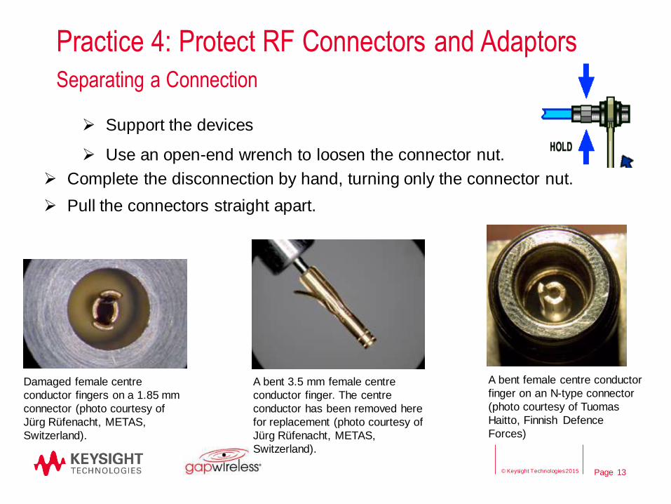
Practice 4: Protect RF Connectors and Adaptors
Separating a Connection
Support the devices
Use an open-end wrench to loosen the connector nut.
13
Complete the disconnection by hand, turning only the connector nut.
Pull the connectors straight apart.
Damaged female centre
conductor fingers on a 1.85 mm
connector (photo courtesy of
Jürg Rüfenacht, METAS,
Switzerland).
A bent 3.5 mm female centre
conductor finger. The centre
conductor has been removed here
for replacement (photo courtesy of
Jürg Rüfenacht, METAS,
Switzerland).
A bent female centre conductor
finger on an N-type connector
(photo courtesy of Tuomas
Haitto, Finnish Defence
Forces)
© Keysight Technologies 2015

Page
Practice 4: Protect RF Connectors and Adaptors
Use Torque Wrench
14
Torque wrench remains straight
when in use
Stop when the handle begins to yield
Example of a Type-N torque wrench
© Keysight Technologies 2015
Page
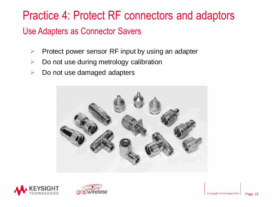
Practice 4: Protect RF connectors and adaptors
Use Adapters as Connector Savers
Protect power sensor RF input by using an adapter
Do not use during metrology calibration
Do not use damaged adapters
15 © Keysight Technologies 2015

Page
Practice 4: Protect RF connectors and adaptors
Visual Inspection
– Use magnifying glass or microscope to look for:
Badly worn plating, deep scratches, dents
Deformed threads
Bent or misaligned center conductor
Debris on the threads or mating surfaces
16
Clean connectors
Clean with compressed air
If required, use lint free swab with minimal alcohol
Avoid plastic parts
Avoid snagging swab on female contact fingers
Let dry and inspect again for residue
© Keysight Technologies 2015

Page
Practice 4: Protect RF Connectors and Adaptors
Use a Gauge
– Pin depth is positive if the center conductor protrudes from the
reference plane.
– Pin depth is negative if the center conductor is recessed below the
reference plane
17
When to gauge connectors
When to gauge connectors :
Prior to first use
When visual inspection or electrical performance suggest connector interface may
be out of typical range
After every 100 connections and as often as experience suggest thereafter
Gauging Connectors: http://na.support.keysight.com/pna/connectorcare/Connector_Care.htm
© Keysight Technologies 2015

Page
Practice 4: Protect RF connectors and adaptors
Handling and Storage
Use plastic end caps during storage
Store in a clean and dry environment at room temperature
Never store connectors loose in a box
Do not touch mating plane surfaces
Do not set connectors contact end down
18 © Keysight Technologies 2015

Page
Practice 5: Ensure Proper Grounding for Power Meter
Always use the three-prong AC power cord supplied with
the power meter
Proper grounding of the instrument will prevent harm to the
instrument and operator
19 © Keysight Technologies 2015

Page
Practice 6: Take ESD Precautions
– ESD (Electro-Static Discharge)
– Electrostatic discharge to the center pin will render the sensor
inoperative
Put connector cap on unused power sensor
Conduct testing at static-safe workstation
Clean RF input connector only at a static-safe workstation
Avoid bringing sources of static electricity within 1meter of a
static-safe workstation
20 © Keysight Technologies 2015

Page
Practice 6: Take ESD Precautions
– Sources of static electricity:
People
Conveyor belts
Other moving machinery
– When removal of the source is not practical, ground the source
21 © Keysight Technologies 2015

Page
Practice 6: Take ESD Precautions
ESD Protection setup
22 © Keysight Technologies 2015

Page
Practice 7: Check for Temperature and Humidity
Keep power sensor and meter in a clean and dry environment
Ensure proper ventilation among rack
Cooling vents and fans should be inspected and cleaned
frequently
Operating environmental conditions
Storage environmental conditions
Relative humidity is a significant factor in ESD
23 © Keysight Technologies 2015

Page
Summary
– Practice 1: Use RF limiter to attenuate high power
– Practice 2: Use DC block to remove DC component
– Practice 3: Adhere to warnings and specifications
– Practice 4: Protect RF connectors and adaptors
– Practice 5: Ensure proper grounding
– Practice 6: Take ESD precautions
– Practice 7: Check for temperature and humidity
24 © Keysight Technologies 2015

Page
References
– Tips for Preventing Damage to Power Sensor & Meter
- http://literature.cdn.keysight.com/litweb/pdf/5990-9136EN.pdf
– AN362 Principles of Microwave Connector Care: excellent reference
– http://na.support.keysight.com/pna/connectorcare/Connector_Care.htm
– Fundamentals of RF and Microwave Power Measurements
– http://www.keysight.com/main/editorial.jspx?cc=US&lc=eng&ckey=272209&nid=-35560.0.00&id=272209
– Selection Guide
– http://literature.cdn.keysight.com/litweb/pdf/5989-6240EN.pdf
25 © Keysight Technologies 2015

Page
Q & A
26 © Keysight Technologies 2015