Embed Size (px)
Citation preview

Power Scaling of Tm:fiber Lasers to the kW Level
Peter F. MoultonQ-Peak, Inc.
CREOLIndustrial Affiliates Day 2009
High Power Optical Sources for the 21st CenturyApril 17, 2009

Outline
• Background• Fundamentals of Tm:silica fiber lasers• Fiber laser setup and results
Support:
HEL-JTO Contract Nos. FA9451-06-D-0009 andFA9451-08-D-0199
Technical work:
Q-Peak: Glen Rines, Evgueni Slobodtchikov, Kevin Wall, Nufern: Gavin Frith, Bryce Samson, Adrian Carter
Relative eye safety is obtainedfor > 1400-nm wavelengths
Retinal focusing can increase the power density by 105

Rare-earth laser transitionscan provide eyesafe wavelengths in fibers
Ener
gy (w
aven
umbe
r/100
00)
1080 nm
1950-2050 nm
1550 nm
1060 nm930 nm

Tm-ion cross relaxation allows excitation of two upper laser levels for one pump photon

Prior work with Tm:YAG lasers
E.C. Honea, R.J. Beach, S.B. Sutton, J. A. Speth, S.C. Mitchell, J.A. Skidmore, M.A. Emanuel, and S.A. Payne, “115-W Tm:YAG Diode-Pumped Solid-State Laser,” J. Quantum Electron. 33, 1592 (1997).
K. S. Lai, P. B. Phua, R. F. Wu, Y. L. Lim, E. Lau, S. W. Toh, B. T. Toh, and A. Chng, "120-W continuous-wave diode-pumped Tm:YAG laser ," Opt. Lett. 25, 1591-1593 (2000)

Recent advances in Tm-doped fiber-laser efficiencies show levels approaching Yb fibers

Fundamentals of Tm:silica fiber lasers

Absorption and emission cross sectionsfor Tm:silica
0.0E+00
5.0E-22
1.0E-21
1.5E-21
2.0E-21
2.5E-21
3.0E-21
3.5E-21
4.0E-21
4.5E-21
5.0E-21
1400 1500 1600 1700 1800 1900 2000 2100 2200 2300
Wavelength (nm)
Cro
ss s
ectio
n (c
m2)
AbsorptionEmission
Abs: NufernEm: Walsh (NASA)

Calculation of net gain in Tm:silica fiber laser
We define the inversion fraction as: F = N2 / (N2 + N1), where N1 and N2 are the inversion densities for the lower and upper Tm:silica laser levels. The net gain (or loss) cross section σ(λ) in the fiber as a function of wavelength, λ, is given by the relation: σ (λ) = F σe (λ) – (1-F) σa (λ), where σe (λ) and σa (λ) are the emission and absorption cross sections. The gain or loss coefficient is σ (λ) multiplied by the concentration of active ions.

Plot of net gain cross section in Tm:silicavs. inversion fraction
-5E-21
-4E-21
-3E-21
-2E-21
-1E-21
0
1E-21
2E-21
3E-21
4E-21
5E-21
1500 1600 1700 1800 1900 2000 2100 2200
Wavelength (nm)
Net
gai
n cr
oss
sect
ion
(cm
2)
1
0.9
0.8
0.7
0.6
0.5
0.4
0.3
0.2
0.1
0.05
Data on emission cross section from Walsh and absorption cross sections from Nufern

Tm:silica gain at low inversions
-2E-22
-1.5E-22
-1E-22
-5E-23
0
5E-23
1E-22
1.5E-22
1900 1920 1940 1960 1980 2000 2020 2040 2060 2080 2100 2120 2140 2160 2180 2200
Wavelength (nm)
Net
gai
n cr
oss
sect
ion
(cm
2)
0.1
0.09
0.08
0.07
0.06
0.05
0.04
0.03
0.02
0.01
Net gain cross sections needed for5-m fiber length, with gain of 25

Polished preforms and sample holder

Absorbance data from Lambda 9 measurements
0
0.05
0.1
0.15
0.2
0.25
0.3
600 650 700 750 800 850
Wavelength (nm)
Abs
orba
nce
HILO
Result:LO: 2.03-2.36 wt% (Tm2O3)HI: 2.47-2.87 wt%

The photodarkening issue has not appeared in pumping highly doped fibers at 790 nm
0
5000
10000
15000
20000
25000
30000
35000
40000
Ener
gy (c
m-1
)
3H6
3F4
3H5
3H4
3F2,3
1G4
1D2
1I63P03P1
3P2
790-nmpump
M.M. Broer, D.M. Krol and D.J. DiGiovanni, “Highly nonlinear near-resonant photodarkening in a thulium-doped aluminosilicate glass fiber,” Opt. Lett. 18, 799 (1993).

Dynamics measurements of Tm:silica
800-nm emission
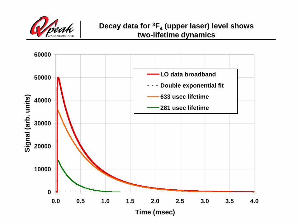
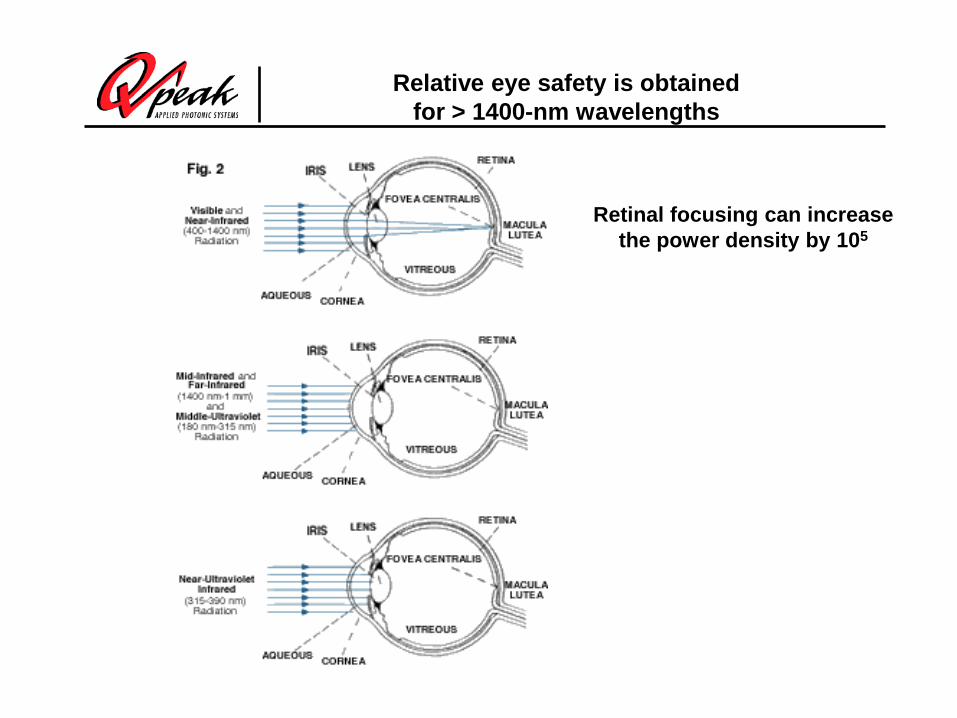
Decay data for 3F4 (upper laser) level showstwo-lifetime dynamics
0
10000
20000
30000
40000
50000
60000
0.0 0.5 1.0 1.5 2.0 2.5 3.0 3.5 4.0
Time (msec)
Sign
al (a
rb. u
nits
)
LO data broadband
Double exponential fit
633 usec lifetime
281 usec lifetime

Initial portion of 3F4 signal showsfeeding from pumped level
0
10000
20000
30000
40000
50000
60000
0.000 0.005 0.010 0.015 0.020 0.025 0.030 0.035 0.040
Time (msec)
Sign
al (a
rb. u
nits
)

800-nm fluorescence provides dataon cross-relaxation efficiency
0
10000
20000
30000
40000
50000
60000
0 10 20 30 40 50 60 70 80 90 100
Time (microseconds)
Sign
al le
vel (
arb.
uni
ts)
LO sample
HI sample
5.6 usec to 1/e
7.9 usec to 1/e
Decay in tail: 24.3 usec (LO), 21.0 usec (HI)
Assuming 45 usec lifetime for low Tm doping, efficiency of cross relaxation:
74% for LO80% for HI

Fiber laser setup and results

Approach to scaling follows on work done by SOTON on Yb:fiber lasers
Diode stack@975 nm, 1.2 kW
Double-clad Yb-doped fibre
HT @975 nmHR @~1.1 µm
Signal output@~1.1 µmHT @975 nm
HR @~1.1 µm
Diode stack@975 nm, 0.6 kW
HT @975 nmHR @~1.1 µm
0.0 0.2 0.4 0.6 0.8 1.0 1.2 1.4 1.6 1.80.0
0.2
0.4
0.6
0.8
1.0
1.2
1.4
Slope efficiency: 83%
Sign
al p
ower
[kW
]
Launched pump powwer [kW]
Measured Linear fit

Details of the 790-nm pump band (2 wt. % Tm) showing broad absorption
0
1
2
3
4
5
6
7
750 760 770 780 790 800 810 820 830 840 850
Wavelength (nm)
Atte
nuat
ion
(dB
/m)

350-W Laserline pump laser (1 of 2)
Rack unit with diodes, power supply and cooler
5-m delivery fiber
High-powerconnector
1:1 lens focusing optics

Pump laser wavelengths were 795 nm at full power
Spectral emission data for pump lasers #1 and #2, respectively at a drive current of 55A, approximately 350 W of power output.

Q-Peak fiber-laser testbed
powermeter
Pump Laser A
Pump Laser B
focusinghead
Meniscus2.5-cm R concave surface
HR at 2050 nmHT at 790 nm
Dichroicmirror
HR at 2050 nmHT at 790 nm
clamp
Heat sink
clamp
Active fiber coil
focusinghead
2050 nm output
793-nm pump400-um, 0.2 NAfiber delivery
Single-ended pump

Characteristics of Nufern-supplied fibers
Fiber ID MM-TDF-20/400-LO
MM-TDF-20/400-Hi
LMA-20/35/400-Hi
Core diameter 17-23µm 17-23µm 17-23µm Clad diameter 385-415µm 385-415µm 385-415µm Core NA (effective) 0.2 0.2 0.1 Cladding NA 0.46 0.46 0.46 V value at 2µm >6 >6 <4 # of modes (2µm) 7 7 2 Cladding absorption (795nm)
~2dB/m ~2.6dB/m ~2.6dB/m
Tm-concentration 2.7wt% 3.5wt% 3.5wt% Cladding Shape Octagon Octagon Octagon
At 790.1 nm (2.5-nm linewidth) we measured 1.09 db/m for LO fiber (10-m length)and 1.54 db/m for HI fiber (7-m length)

Summary of highest-powerLO and HI Tm:fiber lasers
0
25
50
75
100
125
150
175
200
225
250
0 50 100 150 200 250 300 350 400 450 500 550
Launched pump power (W)
Out
put p
ower
(W)
LO fiber data
LO linear fit
HI fiber data
46.3% slope
`

LMA HI2 fiber design used undoped, spliced ends
Fiber assembly: 5-m length of Tm-doped fiber (3), with two undoped,3-m-long fibers (1) fusion-spliced (2) to the ends of the doped fiber
Gain fiber: LMA HI2Cores: 25 µm in diameter, NA: 0.08.Pump claddings: 400-µm in diameter, octagonal cross sectionPump attenuation: 2.9 dB/m
x21
3
x12

300 W from 25/400 Tm:fiber laser
0
25
50
75
100
125
150
175
200
225
250
275
300
325
0 50 100 150 200 250 300 350 400 450 500 550 600
Launched pump power (W)
Out
put p
ower
(W)
LMA HI2 fiber data conduction cooled, new clampsLinear fitLMA HI2 fiber data conduction cooledLinear fitLMA HI2 fiber data water cooledLinear fit
59.1% slope
61.8% slope
301 W
64.5% slope
Slope efficiency data, corrected for absorbed power, is 71.7% in good agreement with the value of 69.8% calculated by spectroscopy. The pump quantum efficiency is 1.84.

LMA HI2 fiber laser beam quality close to D.L.
0
500
1000
1500
200 250 300 350 400EP 7290 camera distance (mm)
Bea
m w
idth
( µm
)
Horiz. raw dataVert. raw dataHoriz. processed dataVert. processed data
Vert. axis, My2=1.16
Horiz. axis, Mx2=1.21

Tuning of LMA HI2 laser limitedon short-wavelength end by high gain
0
2
4
6
8
10
12
14
16
18
20
1960 1980 2000 2020 2040 2060 2080 2100
Wavelength (nm)
Pow
er o
utpu
t (W
)
The laser was pumped from one end with 47 W, and had a 600g/mm Littrow grating as an end mirror

Next: Scale the Tm-doped fiber laser to 1 kW
Fiber coupled diode stacks1000 W at 790 nm, 1000 um 0.22 NA
Double-clad Tm-doped fiber
Cladding 625 um, 0.46 NACore 35 um
HT @790 nmHR @~2 µm
HT @790 nmHR @~2 µm
Signal output@~2 µm
HT @790 nmHR @~2 µm

Rack of pump lasers, 1- kW Q-Peak pump data
350 Wpumps
1 kWpump
Hole forsecond1 kWpump
I/O data from Laserlines 1-kW LDM(S/N 760420)
0
200
400
600
800
1000
1200
1 1.5 2 2.5 3 3.5 4
Current Monitor (V)
Pow
er O
utpu
t (W
)
Power through undoped fiberMM-GDF-625/35
Power through lens assembly
86% transmission through fiber(93% maximum with uncoated ends)
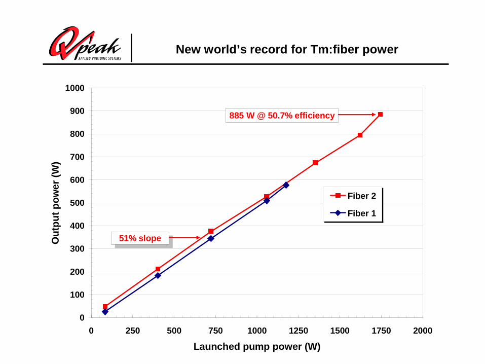
New world’s record for Tm:fiber power
0
100
200
300
400
500
600
700
800
900
1000
0 250 500 750 1000 1250 1500 1750 2000
Launched pump power (W)
Out
put p
ower
(W)
Fiber 2
Fiber 1
51% slope
885 W @ 50.7% efficiency
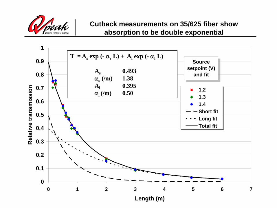
Cutback measurements on 35/625 fiber show absorption to be double exponential
0
0.1
0.2
0.3
0.4
0.5
0.6
0.7
0.8
0.9
1
0 1 2 3 4 5 6 7
Length (m)
Rel
ativ
e tr
ansm
issi
on 1.21.31.4Short fitLong fitTotal fit
Source setpoint (V)
and fit
T = As exp (- αs L) + Al exp (- αl L)
As 0.493αs (/m) 1.38Al 0.395αl (/m) 0.50

Cutback absorption measurements on 400-um cladding fibers - single exponential absorption
0
1
2
3
4
5
6
7
8
0 2 4 6 8 10
Length (m)
Pow
er (W
)LO data
LO fit
LMA HI1 data
LMA HI1 fit
LMA HI2 data
LMA HI2 fit
Fiber Nominal doping
(%)
Cladding absorption coefficient
(/m)
Core absorption coefficient
(/m)
Area ratio Predicted cladding
absorption coefficient
(/m)
Measured/predicted
LO 2.7 0.292 158 0.00250 0.395 0.74 LMA-HI1 3.5 0.438 192 0.00250 0.480 0.91 LMA-HI2 4.5 0.664 247 0.00391 0.965 0.69

Thermal modeling for 200 W/m indicates cladding/buffer temperature well below 100 C
The cladding/ buffer interface reaches 100 C sooner for the smaller diameter fiber even with a thinner buffer
35/625/819 25/400/550Pcritical = 382 W/m Pcritical = 323 W/m

Publication from BAA1

Scaling issues for Tm-doped fiberscompared to Yb-doped fibers
NAa
oλπ= 2V
a is core radius, λ is wavelength
V < 2.405 for single-mode fiber
Optical damage fluence (dielectric breakdown): scales as λ
Raman gain: scales as 1/ λ
Brillouin gain: scales as 1/ (λ)2 x 1/linewidth
Thus, for the same V parameter, compared to Yb-doped fibers,Tm-doped fibers have:
8 X higher fiber end-facet damage threshold
8X higher stimulated Raman scattering threshold
TBD higher stimulated Brillouin scattering threshold

High-power single-frequency results from NGAS
Gregory D. Goodno, Lewis D. Book, and Joshua E. Rothenberg SPIE Photonics West January 27, 2009

Applications of high-power Tm-doped fiber lasers
• Directed energy• IRCM• Remote Sensing for CBW detection• Remote Sensing of Global Winds• Coherent laser radar• Driver for laser ultrasonics NDT for aircraft parts• Pump source for mid-IR ultrafast systems

Ho:YLF MOPA chain produces recordfor hybrid system with Tm:fiber pumps
Ho-stage/ Regime CW 100 Hz 500 Hz
Osc/Amp #1 39 W 55 mJ 50 mJ
Amp#2 76 W 110 mJ 95 mJ
Amp#3 115 W 170 mJ 140 mJ
Tm-pump #1~120 W at 1940 nm
Osc/ Amp #1
Amp #2
Amp #3
Tm-pump #2~120 W at 1940 nm
Tm-pump #3~120 W at 1940 nm
Tm-fiber laser TLR-100-1940 IPG Photonicswww.ipgphotonics.com
Operation regime CWBeam Profile TEMooOutput power ≥ 120 WWavelength 1940 nmPolarization RandomLinewidth ≤ 2 nm
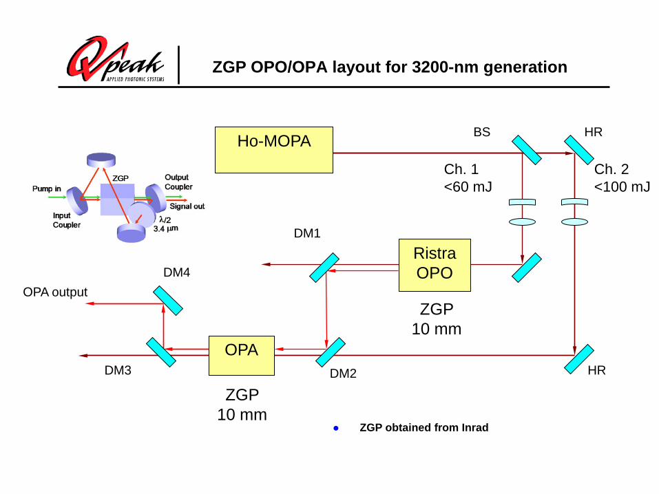
ZGP OPO/OPA layout for 3200-nm generation
Ho-MOPA
Ristra OPO
DM1
DM2
DM4
DM3
BS
OPA output
Ch. 2<100 mJ
Ch. 1<60 mJ
OPA
HR
HR
ZGP 10 mm
ZGP 10 mm
ZGP obtained from Inrad

0
5
10
15
20
25
30
35
0 20 40 60 80 100 120
Ho-pump energy (mJ)
OPA
out
put (
mJ)
100 Hz300 Hz500 Hz
Signal seed ~10 mJ
Signal seed ~9 mJ
Signal seed ~9 mJ
ZGP OPA - various repetition rates
500 Hz
OPA pump beam size remains optimized for max pulse energy of ~100 mJ (100 Hz)

Cr:ZnSe CPA system based on Tm:fiber pumps
1.9-2.0-µm5-W P M T m:fiberC W pump laser
2.5-µmC E P -s tabilized C r:Z nS e
femtosecond laser(100 fs , 1 nJ , 100 MHz)
C E P -s tabilization
setup
P ulse s tretcher100 fs 100 ps
2.5-µmC r:Z nS e regenerative
amplifier(4.5 mJ , 1 kHz)
2.05-µmHo:Y L F Q-s witched
pump laser(17 mJ , 1 kHz)
1.94-µm50-W T m:fiber
C W pump laser
P ulse compressor
Output:2.5 µm, 100 fs
3 mJ , 1 kHz

CW Cr:ZnSe laser generates130 fs pulses at 2530 nm
-200 -100 0 100 200
-0.2
0
0.2
0.4
0.6
0.8
1
Time [fs]
Am
plitu
de [a
u]
T m:fiberlaser
S E S AM
C r:Z nS e
R O C = 150 mm
R O C = 100 mm
2% O .C .
C aF 2 prisms
T m:fiberlaser
S E S AM
C r:Z nS e
R O C = 150 mm
R O C = 100 mm
2% O .C .
C aF 2 prisms

Conclusions
• Tm:silica fiber lasers may provide power levels and efficiencies approaching that of Yb:silica fibers
• We have measured some fundamental properties of Tm:silica to better understand laser operation
• With a 25/35/400 Tm:silica fiber laser, we generated 301 W, with 60% conversion of launched pump power to laser output
• The laser slope efficiency indicates that each pump photon generates 1.84 laser photons
• With a 35/625 Tm:silica laser we have generated 885 W of power, a new record for this technology.