Embed Size (px)
Citation preview
1
FTR-K1 SERIES
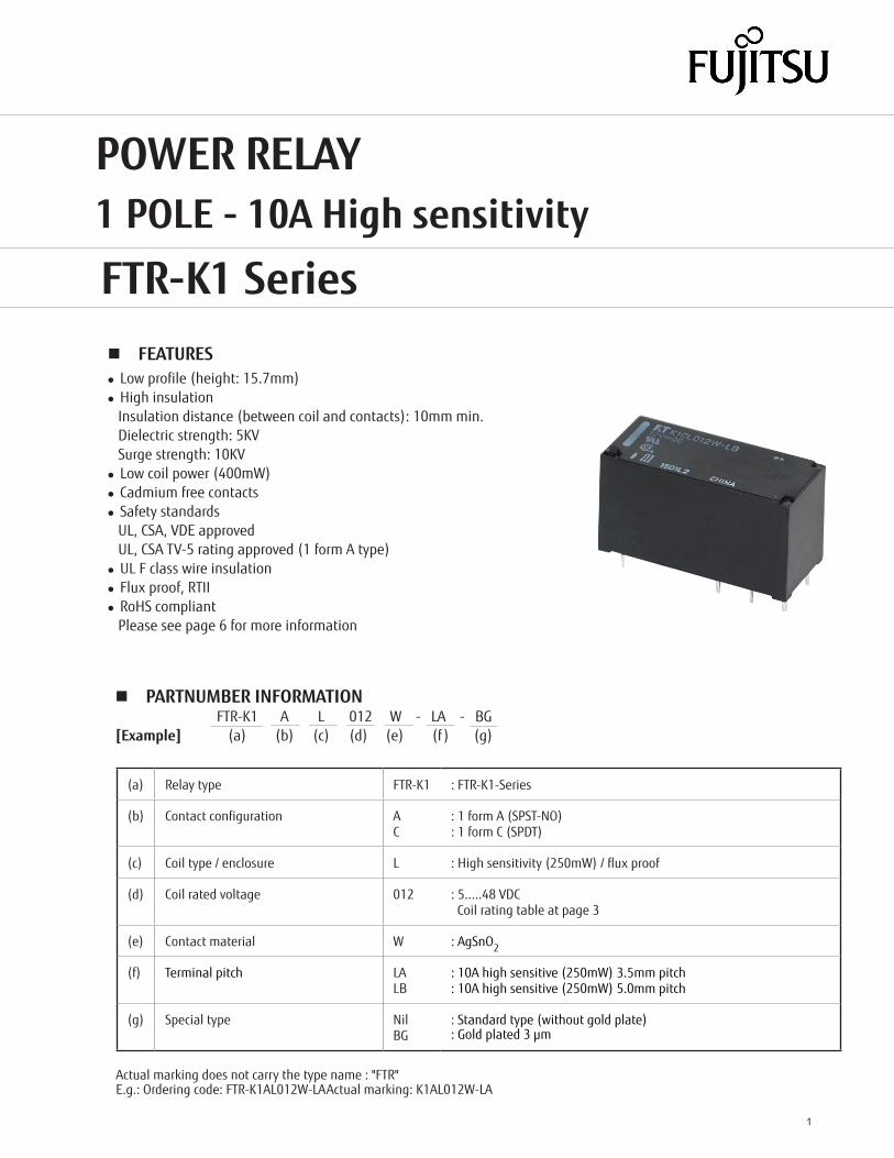
n FEATURESl Low profile (height: 15.7mm)l High insulation Insulation distance (between coil and contacts): 10mm min. Dielectric strength: 5KV Surge strength: 10KVl Low coil power (400mW)l Cadmium free contactsl Safety standards UL, CSA, VDE approved UL, CSA TV-5 rating approved (1 form A type)l UL F class wire insulationl Flux proof, RTIIl RoHS compliant Please see page 6 for more information
Actual marking does not carry the type name : "FTR"E.g.: Ordering code: FTR-K1AL012W-LA Actual marking: K1AL012W-LA
POWER RELAY1 POLE - 10A High sensitivity
FTR-K1 Series
n PARTNUMBER INFORMATION FTR-K1 A L 012 W - LA - BG[Example] (a) (b) (c) (d) (e) (f ) (g)
(a) Relay type FTR-K1 : FTR-K1-Series
(b) Contact configuration AC
: 1 form A (SPST-NO): 1 form C (SPDT)
(c) Coil type / enclosure L : High sensitivity (250mW) / flux proof
(d) Coil rated voltage 012 : 5.....48 VDC Coil rating table at page 3
(e) Contact material W : AgSnO2
(f) Terminal pitch LALB
: 10A high sensitive (250mW) 3.5mm pitch: 10A high sensitive (250mW) 5.0mm pitch
(g) Special type NilBG
: Standard type (without gold plate): Gold plated 3 µm
2
FTR-K1 SERIES
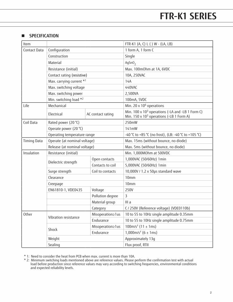
n SPECIFICATION
Item FTR-K1 (A, C) L ( ) W - (LA, LB)
Contact Data Configuration 1 form A, 1 form C
Construction Single
Material AgSnO2
Resistance (initial) Max. 100mOhm at 1A, 6VDC
Contact rating (resistive) 10A, 250VAC
Max. carrying current *1 14A
Max. switching voltage 440VAC
Max. switching power 2,500VA
Min. switching load *2 100mA, 5VDC
Life Mechanical Min. 20 x 106 operations
Electrical AC contact rating Min. 100 x 103 operations (-LA and -LB 1 Form C)Min. 150 x 103 operations (-LB 1 Form A)
Coil Data Rated power (20 °C) 250mW
Operate power (20 °C) 141mW
Operating temperature range -40 °C to +85 °C (no frost), (LB: -40 °C to +105 °C)
Timing Data Operate (at nominal voltage) Max. 15ms (without bounce, no diode)
Release (at nominal voltage) Max. 5ms (without bounce, no diode)
Insulation Resistance (initial) Min. 1,000MOhm at 500VDC
Dielectric strengthOpen contacts 1,000VAC (50/60Hz) 1min
Contacts to coil 5,000VAC (50/60Hz) 1min
Surge strength Coil to contacts 10,000V / 1.2 x 50µs standard wave
Clearance 10mm
Creepage 10mm
EN61810-1, VDE0435 Voltage 250V
Pollution degree 3
Material group III a
Category C / 250V (Reference voltage) (VDE0110b)
OtherVibration resistance
Misoperation≥1us 10 to 55 to 10Hz single amplitude 0.35mm
Endurance 10 to 55 to 10Hz single amplitude 0.75mm
ShockMisoperation≥1us 100m/s² (11 ± 1ms)
Endurance 1,000m/s² (6 ± 1ms)
Weight Approximately 13g
Sealing Flux proof, RTII
* 1: Need to consider the heat from PCB when max. current is more than 10A.* 2: Minimum switching loads mentioned above are reference values. Please perform the confirmation test with actual load before production since reference values may vary according to switching frequencies, environmental conditions and expected reliability levels.
FTR-K1 SERIES
3
FTR-K1 SERIES
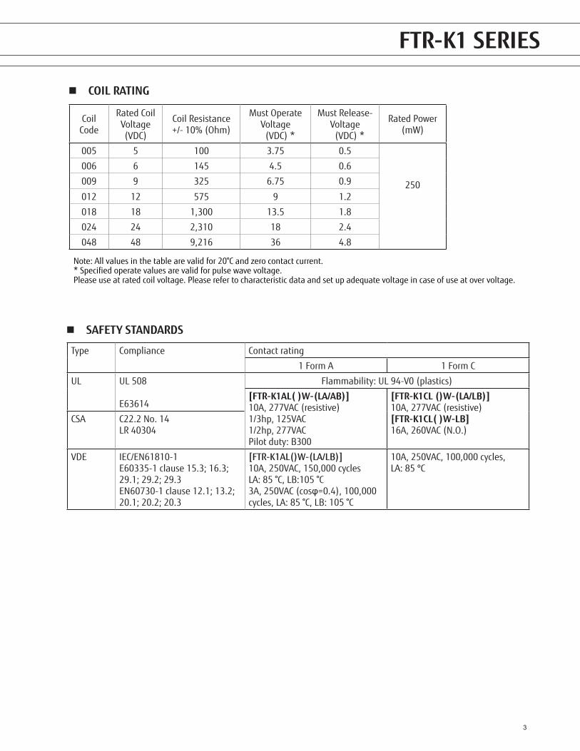
n COIL RATING
Coil Code
Rated Coil Voltage (VDC)
Coil Resistance +/- 10% (Ohm)
Must Operate Voltage
(VDC) *
Must Release-Voltage
(VDC) *
Rated Power (mW)
005 5 100 3.75 0.5
250
006 6 145 4.5 0.6
009 9 325 6.75 0.9
012 12 575 9 1.2
018 18 1,300 13.5 1.8
024 24 2,310 18 2.4
048 48 9,216 36 4.8
Note: All values in the table are valid for 20°C and zero contact current.* Specified operate values are valid for pulse wave voltage.Please use at rated coil voltage. Please refer to characteristic data and set up adequate voltage in case of use at over voltage.
Type Compliance Contact rating
1 Form A 1 Form C
UL UL 508
E63614
Flammability: UL 94-V0 (plastics)
[FTR-K1AL( )W-(LA/AB)]10A, 277VAC (resistive)1/3hp, 125VAC1/2hp, 277VACPilot duty: B300
[FTR-K1CL ()W-(LA/LB)]10A, 277VAC (resistive)[FTR-K1CL( )W-LB]16A, 260VAC (N.O.)
CSA C22.2 No. 14LR 40304
VDE IEC/EN61810-1E60335-1 clause 15.3; 16.3; 29.1; 29.2; 29.3EN60730-1 clause 12.1; 13.2; 20.1; 20.2; 20.3
[FTR-K1AL()W-(LA/LB)]10A, 250VAC, 150,000 cyclesLA: 85 °C, LB:105 °C3A, 250VAC (cosφ=0.4), 100,000 cycles, LA: 85 °C, LB: 105 °C
10A, 250VAC, 100,000 cycles, LA: 85 ºC
n SAFETY STANDARDS
FTR-F4 SERIES FTR-K1 SERIES
4
FTR-K1 SERIES FTR-F4 SERIES
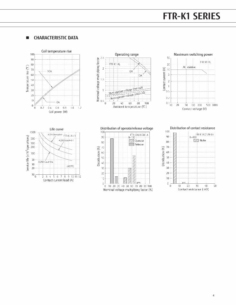
n CHARACTERISTIC DATA
FTR-K1 SERIES
5
FTR-K1 SERIES
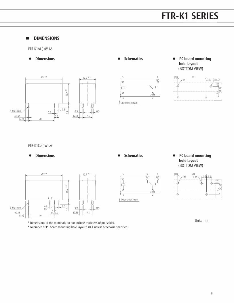
n DIMENSIONS
FTR-F4 SERIES
Unit: mm
FTR-K1 SERIES
l Dimensions l PC board mounting hole layout (BOTTOM VIEW)
l Schematics
FTR-K1AL( )W-LA
l Dimensions l PC board mounting hole layout (BOTTOM VIEW)
l Schematics
FTR-K1CL( )W-LA
3.3
0.45φ0.3
0.5
(2.6)(2.6)
203.5
29 +0.3
15.7
+0.3
0.9 0.9
7.5
12.7 +0.3
4- Pre solder
5
4 2
8
COM
NO
Orientation mark
(2.6)
(12.
7)
(2.6)
20
7.5
3.5 1.32-φ12-φ
3.3
0.45φ
0.50.3
0.5
(2.6)(2.6)
203.5 3.5
29 +0.3
15.7
+0.3
0.9 0.9
7.5
12.7 +0.3
( )
5- Pre solder
5
4 2
86NC
COM
NO
Orientation mark
(2.6)
(12.
7)(2
.6)
20
7.5
3.5 3.51.33-φ12-φ
* Dimensions of the terminals do not include thickness of pre-solder. * Tolerance of PC board mounting hole layout : ±0.1 unless otherwise specified.
6
FTR-K1 SERIES
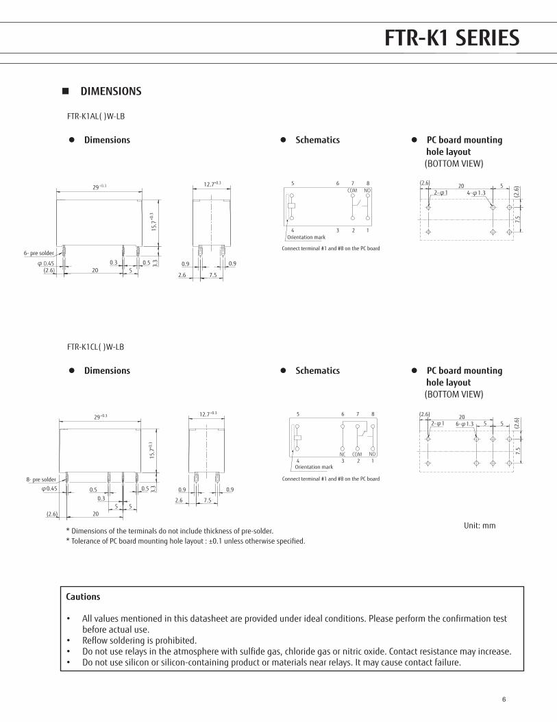
n DIMENSIONS
FTR-F4 SERIES
Unit: mm
FTR-K1 SERIES
l Dimensions l PC board mounting hole layout (BOTTOM VIEW)
l Schematics
FTR-K1AL( )W-LB
l Dimensions l PC board mounting hole layout (BOTTOM VIEW)
l Schematics
FTR-K1CL( )W-LB
2.6
12.7+0.3
7.5
0.90.9
15.7
29 +0.3
520(2.6)0.50.30.45 3.
3+0
.3
φ6- pre solder
COM NO5 6 7 8
4 3 2 1 Orientation mark
Connect terminal #1 and #8 on the PC board
7.5
520(2.6)
2-φ1 (2.6
)
4-φ1.3
2.6
12.7+0.3
7.5
0.90.9
15.7
+0.3
29+0.3
5520(2.6)
0.5
0.3
0.5 3.3
8- pre solder
φ0.45
NC COM NO
5 6 7 8
4 3 2 1Orientation mark
Connect terminal #1 and #8 on the PC board
7.5
5520(2.6)
2-φ1
(2.6
)
6-φ1.3
Cautions
• All values mentioned in this datasheet are provided under ideal conditions. Please perform the confirmation test before actual use.
• Reflow soldering is prohibited.• Do not use relays in the atmosphere with sulfide gas, chloride gas or nitric oxide. Contact resistance may increase.• Do not use silicon or silicon-containing product or materials near relays. It may cause contact failure.
* Dimensions of the terminals do not include thickness of pre-solder. * Tolerance of PC board mounting hole layout : ±0.1 unless otherwise specified.
7
FTR-K1 SERIES FTR-F4 SERIES FTR-K1 SERIES
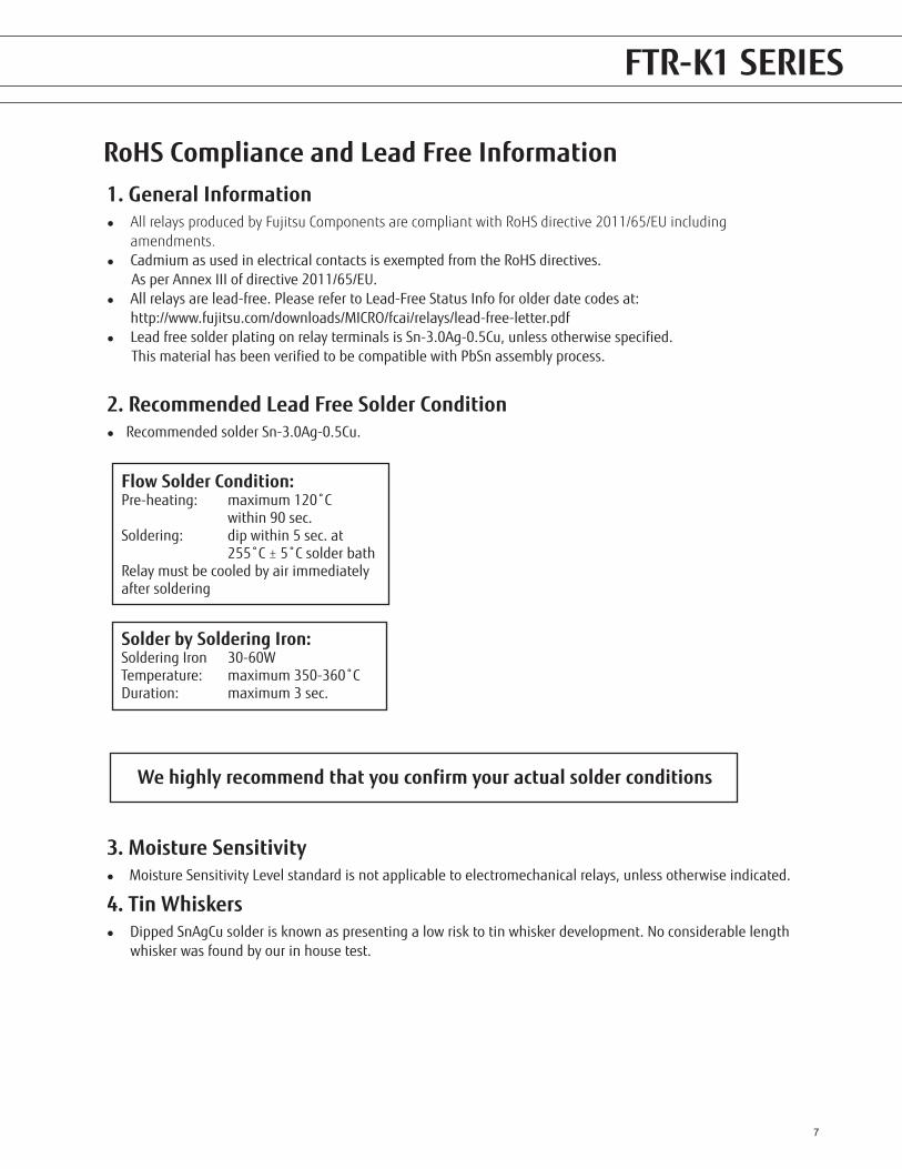
1. General Informationl All relays produced by Fujitsu Components are compliant with RoHS directive 2011/65/EU including amendments.l Cadmium as used in electrical contacts is exempted from the RoHS directives. As per Annex III of directive 2011/65/EU.l All relays are lead-free. Please refer to Lead-Free Status Info for older date codes at: http://www.fujitsu.com/downloads/MICRO/fcai/relays/lead-free-letter.pdfl Lead free solder plating on relay terminals is Sn-3.0Ag-0.5Cu, unless otherwise specified. This material has been verified to be compatible with PbSn assembly process.
2. Recommended Lead Free Solder Conditionl Recommended solder Sn-3.0Ag-0.5Cu.
RoHS Compliance and Lead Free Information
3. Moisture Sensitivityl Moisture Sensitivity Level standard is not applicable to electromechanical relays, unless otherwise indicated.
4. Tin Whiskersl Dipped SnAgCu solder is known as presenting a low risk to tin whisker development. No considerable length whisker was found by our in house test.
We highly recommend that you confirm your actual solder conditions
Flow Solder Condition:Pre-heating: maximum 120˚C within 90 sec.Soldering: dip within 5 sec. at 255˚C ± 5˚C solder bathRelay must be cooled by air immediatelyafter soldering
Solder by Soldering Iron:Soldering Iron 30-60WTemperature: maximum 350-360˚CDuration: maximum 3 sec.
8
FTR-K1 SERIES FTR-F4 SERIES FTR-K1 SERIES
Fujitsu Components International Headquarter Offices
©2018 Fujitsu Components Europe B.V. All rights reserved. All trademarks or registered trademarks are the property of their respective owners.
The contents, data and information in this datasheet are provided by Fujitsu Component Ltd. as a service only to its user and only for general information purposes.The use of the contents, data and information provided in this datasheet is at the users’ own risk. Fujitsu has assembled this datasheet with care and will endeavor to keep the contents, data and information correct, accurate, comprehensive, complete and up to date. Fujitsu Components Europe B.V. and affiliated companies do however not accept any responsibility or liability on their behalf, nor on behalf of its employees, for any loss or damage, direct, indirect or consequential, with respect to this datasheet, its contents, data, and information and related graphics and the correctness, reliability, accuracy, comprehensiveness, usefulness, availability and completeness thereof. Nor do Fujitsu Components Europe B.V. and affiliated companies accept on their behalf, nor on behalf of its employees, any responsibility or liability for any representation or warrant of any kind, express or implied, including warranties of any kind for merchantability or fitness for particular use, with respect to these datasheets, its contents, data, information and related graphics and the correctness, reliability, accuracy, comprehensiveness, usefulness, availability and completeness thereof. Rev. August 29, 2018
JapanFUJITSU COMPONENT LIMITEDShinagawa Seaside Park Tower 19F,12-4, Higashi-shinagawa 4-chome, Shinagawa-ku,Tokyo,140-0002, JapanTel: (81-3) 3450-1682Fax: (81-3) 3474-2385Email: [email protected]: www.fujitsu.com/jp/fcl/
North and South AmericaFUJITSU COMPONENTS AMERICA, INC2290 North First Street, Suite 212San Jose, CA 95131, USATel: (1-408) 745-4900Fax: (1-408) 745-4970Email: [email protected]: us.fujitsu.com/components
EuropeFUJITSU COMPONENTS EUROPE B.V.Diamantlaan 252132 WV HoofddorpNetherlandsTel: (31-23) 5560910Fax: (31-23) 5560950Email: [email protected]: www.fujitsu.com/uk/components
Asia PacificFUJITSU COMPONENTS ASIA, LTD.102E Pasir Panjang Road#01-01 Citilink Warehouse ComplexSingapore 118529Tel: (65) 6375-8560Fax: (65) 6273-3021Email: [email protected]: www.fujitsu.com/sg/products/devices/components
ChinaFUJITSU ELECTRONIC COMPONENTS (SHANGHAI) CO., LTD.Unit 4306, InterContinental Center100 Yu Tong Road, Shanghai 200070, ChinaTel: (86-21) 3253 0998Fax: (86-21) 3253 0997Email: [email protected]: www.fujitsu.com/sg/products/devices/components
Hong KongFUJITSU COMPONENTS HONG KONG CO., LTDUnit 506, Inter-Continental PlazaNo.94 Granville Road, Tsim Sha Tsui, Kowloon,Hong KongTel: (852) 2881-8495Tex: (852) 2894-9512Email: [email protected]: www.fujitsu.com/sg/products/devices/components/
KoreaFUJITSU COMPONENTS KOREA LIMITEDAlpha Tower #403, 645 Sampyeong-dong, Bundang-gu, Seongnam-si, Gyeonggi-do, 13524 Korea Tel: (82) 31-708-7108Fax: (82) 31-709-7108Email: [email protected]/sg/products/devices/components/