Embed Size (px)
Citation preview
www.ijatir.org
ISSN 2348–2370
Vol.08,Issue.07,
July-2016,
Pages:1421-1427
Copyright @ 2016 IJATIR. All rights reserved.
Power Quality Improvement by using Fuzzy Based Grid-Connected Dual
Voltage Source Inverter P. MALLIKARJUN
1, S. KARUNAKAR
2
1PG Scholar, Dept of EEE, Prasad Engineering College, Shameerpet, Jangaon, Warangal, TS, India.
2Assistant Professor, Dept of EEE, Prasad Engineering College, Shameerpet, Jangaon, Warangal, TS, India.
Abstract: The main aim of project is to improve the power
quality by using fuzzy based grid connected dual voltage
source inverter. The proposed scheme is comprised of two
inverters, which enables the micro grid to exchange power
generated by the distributed energy resources (DERs) and also
to compensate the local unbalanced and nonlinear load. The
control algorithms are developed based on instantaneous
symmetrical component theory (ISCT) to operate DVSI in
grid sharing and grid injecting modes. The proposed scheme
has increased reliability, lower bandwidth requirement of the
main inverter, lower cost due to reduction in filter size, and
better utilization of micro grid power while using reduced dc-
link voltage rating for the main inverter. These features make
the DVSI scheme a promising option for micro grid supplying
sensitive loads. the proposed topology validated through
simulation results.
Keywords: Power Quality, Distributed Energy Source, Fuzzy
Controller, Grid Connected Inverter, Instantaneous
Symmetrical Component Theory (ISCT).
I. INTRODUCTION
The proliferation of power electronics devices and electrical
loads with unbalanced nonlinear currents has degraded the
power quality in the power distribution network. Moreover, if
there is a considerable amount of feeder impedance in the
distribution systems, the propagation of these harmonic
currents distorts the voltage at the point of common coupling
(PCC). At the same instant, industry automation has reached
to a very high level of sophistication, where plants like
automobile manufacturing units, chemical factories, and
semiconductor industries require clean power. For these
applications, it is essential to compensate nonlinear and
unbalanced load currents. Load compensation and power
injection using grid interactive inverters in micro grid have
been presented in the literature. A single inverter system with
power quality enhancement is discussed in. The main focus of
this work is to realize dual functionalities in an inverter that
would provide the active power injection from a solar PV
system and also works as an active power filter, compensating
unbalances and the reactive power required by other loads
connected to the system. In , a voltage regulation and power
flow control scheme for a wind energy system (WES) is
proposed. A distribution static compensator (DSTATCOM) is
utilized for voltage regulation and also for active power
injection. The control scheme maintains the power balance
at the grid terminal during the wind variations using sliding
mode control. A multifunctional power electronic
converter for the DG power system is described in. This
scheme has the capability to inject power generated by
WES and also to perform as a harmonic compensator. Most
of the reported literature in this area discuss the topologies
and control algorithms to provide load compensation
capability in the same inverter in addition to their active
power injection. When a grid-connected inverter is used for
active power injection as well as for load compensation,
the inverter capacity that can be utilized for achieving the
second objective is decided by the available instantaneous
micro grid real power.
Considering the case of a grid-connected PV inverter,
the available capacity of the inverter to supply the reactive
power becomes less during the maximum solar insolation
periods. At the same instant, the reactive power to regulate
the PCC voltage is very much needed during this period. It
indicates that providing multi functionalities in a single
inverter degrades either the real power injection or the load
compensation capabilities. This paper demonstrates a dual
voltage source inverter (DVSI) scheme, in which the power
generated by the micro grid is injected as real power by the
main voltage source inverter (MVSI) and the reactive,
harmonic, and unbalanced load compensation is performed
by auxiliary voltage source inverter (AVSI). This has an
advantage that the rated capacity of MVSI can always be
used to inject real power to the grid, if sufficient renewable
power is available at the dc link. In the DVSI scheme, as
total load power is supplied by two inverters, power losses
across the semiconductor switches of each inverter are
reduced. This increases its reliability as compared to a
single inverter with multifunctional capabilities. Also,
smaller size modular inverters can operate at high
switching frequencies with a reduced size of interfacing
inductor, the filter cost gets reduced. Moreover, as the main
inverter is supplying real power, the inverter has to track
the fundamental positive sequence of current. This reduces
the bandwidth requirement of the main inverter. The
inverters in the proposed scheme use two separate dc links.
Since the auxiliary inverter is supplying zero sequence of
load current, a three-phase three-leg inverter topology with
P. MALLIKARJUN, S. KARUNAKAR
International Journal of Advanced Technology and Innovative Research
Volume. 08, IssueNo.07, July-2016, Pages: 1421-1427
a single dc storage capacitor can be used for the main inverter.
This in turn reduces the dc-link voltage requirement of the
main inverter. Thus, the use of two separate inverters in the
proposed DVSI scheme provides increased reliability, better
utilization of micro grid power, reduced dc grid voltage rating,
less bandwidth requirement of the main inverter, and reduced
filter size. Control algorithms are developed by instantaneous
symmetrical component theory (ISCT) to operate DVSI in
grid-connected mode, while considering non stiff grid voltage.
II. FUZZY LOGIC CONTROLLER Fuzzy logic is an innovative technology that enhances
conventional system design with engineering expertise. Using
fuzzy logic, we can circumvent the need for rigorous
mathematical modeling A human operator is far more
successful in controlling a process than a controller designed
by modern analytical technique. So it is worth simulating the
control strategy based upon intuition and experience and can
be considered as heuristic decision or rule of thumb decision.
In academic and technological arena, Fuzzy is a technical term
that deals with ambiguity or vagueness based on human
intuitions. Professor Lotfi A Zadeh introduced the concept of
fuzzy sets, according to him. Fuzzy logic is a mathematical
imprecise description. During the past several years, FLC has
emerged as one of the most active area of research for the
application of fuzzy set theory. A fuzzy set is a generalization
of the concept of an ordinary set in which the membership
function (MF) values can be only one of the two values, 0 and
1. A fuzzy set can be defined as below. Fuzzy set A in a
universe of discourse U is characterized by a MF A: U [0]
[1] and associates with each element x of U a number A (x) in
the interval [1] representing the degree of membership of x in
A.
A. Fuzzy Controller Model
Fuzzy modeling is the method of describing the
characteristics of a system using fuzzy inference rules. The
method has a distinguishing feature in that it can express
linguistically complex non-linear system.
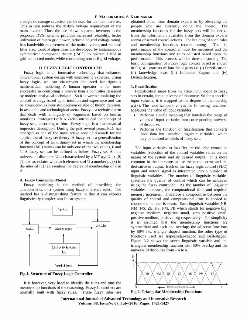
Fig.1. Structure of Fuzzy Logic Controller
It is however, very hand to identify the rules and tune the
membership functions of the reasoning. Fuzzy Controllers are
normally built with fuzzy rules. These fuzzy rules are
obtained either from domain experts or by observing the
people who are currently doing the control. The
membership functions for the fuzzy sets will be derive
from the information available from the domain experts
and/or observed control actions. The building of such rules
and membership functions require tuning. That is,
performance of the controller must be measured and the
membership functions and rules adjusted based upon the
performance. This process will be time consuming. The
basic configuration of Fuzzy logic control based as shown
in Fig. 4.1 consists of four main parts i.e. (i) Fuzzification,
(ii) knowledge base, (iii) Inference Engine and (iv)
Defuzzification.
1. Fuzzification
Fuzzification maps from the crisp input space to fuzzy
sets in certain, input universe of discourse. So for a specific
input value x, it is mapped to the degree of membership
A(x). The fuzzification involves the following functions.
Measures the value of input variables.
Performs a scale mapping that transfers the range of
values of input variables into corresponding universe
of discourse.
Performs the function of fuzzification that converts
input data into suitable linguistic variables, which
may be viewed as labels of fuzzy sets.
The input variables to fuzzifier are the crisp controlled
variables. Selection of the control variables relies on the
nature of the system and its desired output. It is more
common in the literature to use the output error and the
derivative of output. Each of the fuzzy logic control (FLC)
input and output signal is interpreted into a number of
linguistic variables. The number of linguistic variables
specifies the quality of control which can be achieved
using the fuzzy controller. As the number of linguistic
variables increases, the computational time and required
memory increases. Therefore a compromise between the
quality of control and computational time is needed to
choose the number is seven. Each linguistic variables NB,
NM, NS, ZE, PS, PM, PB which stands for negative big,
negative medium, negative small, zero positive small,
positive medium, positive big respectively. For simplicity
it is assumed that the membership functions are
symmetrical and each one overlaps the adjacent functions
by 50% i.e., triangle shaped function, the other type of
functions used are trapezoidal-shaped and Bell-shaped.
Figure 3.2 shows the seven linguistic variable and the
triangular membership function with 50% overlap and the
universe of discourse from – a to a.
Fig.2. Triangular Membership Functions
Power Quality Improvement by using Fuzzy Based Grid-Connected Dual Voltage Source Inverter
International Journal of Advanced Technology and Innovative Research
Volume. 08, IssueNo.07, July-2016, Pages: 1421-1427
2. Knowledge Base (KB)
Knowledge base comprises of the definitions of fuzzy MFs
for the input and output variables and the necessary control
rules, which specify the control action by using linguistic
terms. It consists of a database and linguistic control rule base.
The database provides necessary definitions, which are
used to define linguistic control rules and fuzzy data,
manipulation in a FLC.
The rule base characterizes the control goals and control
policy of the domain experts by means of a set of a set of
linguistic control rules.
3. Inference Mechanism
The Decision–Making Logic Which plays an essential role
and contains a set of fuzzy if-then rules such as
IF x is A and y is B then z is C
Where x, y and z are linguistic variables representing two
input variables and one control output: A, B and C are
linguistic values. It is kernel of an FLC, it has the capability of
simulating human decision making based on fuzzy control
actions employing fuzzy implication and the rules of inference
in fuzzy logic. In general, fuzzy systems map input fuzzy sets
to output fuzzy sets, fuzzy rules are the relation between
input/output fuzzy sets. They are usually in the form if A. (set
of conditions are satisfied ) then B, (set of consequences can
be inferred). Each rule defines a fuzzy path in the Cartesian
product A x B (system state space). The antecedents of each
fuzzy rule describe a fuzzy input region in the state space. For
a system of two-control variable with seven linguistic
variables in each range, this leads to a 7x7 decision table. The
knowledge required to generate the fuzzy rules can be derived
from an off – line simulation, an expert operator and/or a
design engineer. Some knowledge can be used on the
understanding of the dynamic system under control. A lot of
effort has been devoted to the creation of the fuzzy rules.
Normally rule definition is based on the operator’s experience
and the engineer’s knowledge. However, it has been noticed
in practice that for monotonic systems a symmetrical rule
table is very appropriate, although sometimes it may need
slight adjustment based on behavior of the specific system. If
the system dynamics are not known or if the system is highly
non – linear, trial and error procedure and experience play an
important role in defining the rules.
4. Defuzzification
Defuzzification converts the linguistic variables to
determine numerical values. Centroid method of
defuzzification is used in this study.
A scale mapping, which converts the range of values of
input variables into corresponding universe of discourse.
Defuzzification, which yields a non-fuzzy control action
from an inferred fuzzy control action.
We defuzzify the output distribution B to produce a single
numerical output, a single value in the output universe of
discourse Y = {y1, y2…yp}. The information in the output
waveform B resides largely in the relative values of
membership degrees. The simplest deuzzificatioin scheme
chooses that, element Ymax. That has maximal membership
put in the output fuzzy ser B. MB (ymax) = max mB (yj); 1
j k The maximum membership defuzzificatioin scheme
has two fundamental problems. First, the mode of the B
distribution is not unique. In practice B is often highly
asymmetric; even if it is unimodal infinitely many output
distributions can share the same mode. The maximum
membership scheme ignores the information in much of the
waveform B. The natural alternative is the fuzzy centroid
defuzzificatioin scheme. The regions in which the control
actions are overlapped depending upon their membership
function. The area thus obtained is divided into narrow
strips of equal width of each vertical line, the membership
function and the corresponding point on the universe of
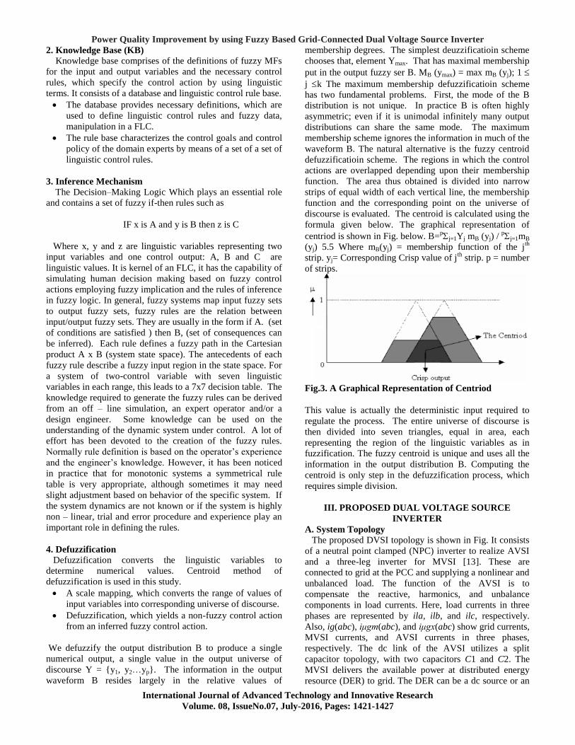
discourse is evaluated. The centroid is calculated using the
formula given below. The graphical representation of
centriod is shown in Fig. below. B=pj=1Yj mB (yj) /
pj=1mB
(yj) 5.5 Where mB(yj) = membership function of the jth
strip. yj= Corresponding Crisp value of jth
strip. p = number
of strips.
Fig.3. A Graphical Representation of Centriod
This value is actually the deterministic input required to
regulate the process. The entire universe of discourse is
then divided into seven triangles, equal in area, each
representing the region of the linguistic variables as in
fuzzification. The fuzzy centroid is unique and uses all the
information in the output distribution B. Computing the
centroid is only step in the defuzzification process, which
requires simple division.
III. PROPOSED DUAL VOLTAGE SOURCE
INVERTER
A. System Topology
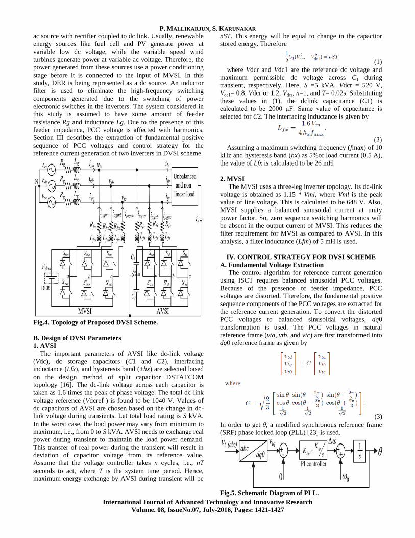
The proposed DVSI topology is shown in Fig. It consists
of a neutral point clamped (NPC) inverter to realize AVSI
and a three-leg inverter for MVSI [13]. These are
connected to grid at the PCC and supplying a nonlinear and
unbalanced load. The function of the AVSI is to
compensate the reactive, harmonics, and unbalance
components in load currents. Here, load currents in three
phases are represented by ila, ilb, and ilc, respectively.
Also, ig(abc), iμgm(abc), and iμgx(abc) show grid currents,
MVSI currents, and AVSI currents in three phases,
respectively. The dc link of the AVSI utilizes a split
capacitor topology, with two capacitors C1 and C2. The
MVSI delivers the available power at distributed energy
resource (DER) to grid. The DER can be a dc source or an
P. MALLIKARJUN, S. KARUNAKAR
International Journal of Advanced Technology and Innovative Research
Volume. 08, IssueNo.07, July-2016, Pages: 1421-1427
ac source with rectifier coupled to dc link. Usually, renewable
energy sources like fuel cell and PV generate power at
variable low dc voltage, while the variable speed wind
turbines generate power at variable ac voltage. Therefore, the
power generated from these sources use a power conditioning
stage before it is connected to the input of MVSI. In this
study, DER is being represented as a dc source. An inductor
filter is used to eliminate the high-frequency switching
components generated due to the switching of power
electronic switches in the inverters. The system considered in
this study is assumed to have some amount of feeder
resistance Rg and inductance Lg. Due to the presence of this
feeder impedance, PCC voltage is affected with harmonics.
Section III describes the extraction of fundamental positive
sequence of PCC voltages and control strategy for the
reference current generation of two inverters in DVSI scheme.
Fig.4. Topology of Proposed DVSI Scheme.
B. Design of DVSI Parameters
1. AVSI
The important parameters of AVSI like dc-link voltage
(Vdc), dc storage capacitors (C1 and C2), interfacing
inductance (Lfx), and hysteresis band (±hx) are selected based
on the design method of split capacitor DSTATCOM
topology [16]. The dc-link voltage across each capacitor is
taken as 1.6 times the peak of phase voltage. The total dc-link
voltage reference (Vdcref ) is found to be 1040 V. Values of
dc capacitors of AVSI are chosen based on the change in dc-
link voltage during transients. Let total load rating is S kVA.
In the worst case, the load power may vary from minimum to
maximum, i.e., from 0 to S kVA. AVSI needs to exchange real
power during transient to maintain the load power demand.
This transfer of real power during the transient will result in
deviation of capacitor voltage from its reference value.
Assume that the voltage controller takes n cycles, i.e., nT
seconds to act, where T is the system time period. Hence,
maximum energy exchange by AVSI during transient will be
nST. This energy will be equal to change in the capacitor
stored energy. Therefore
(1)
where Vdcr and Vdc1 are the reference dc voltage and
maximum permissible dc voltage across C1 during
transient, respectively. Here, S =5 kVA, Vdcr = 520 V,
Vdc1= 0.8, Vdcr or 1.2, Vdcr, n=1, and T= 0.02s. Substituting
these values in (1), the dclink capacitance (C1) is
calculated to be 2000 μF. Same value of capacitance is
selected for C2. The interfacing inductance is given by
(2)
Assuming a maximum switching frequency (fmax) of 10
kHz and hysteresis band (hx) as 5%of load current (0.5 A),
the value of Lfx is calculated to be 26 mH.
2. MVSI
The MVSI uses a three-leg inverter topology. Its dc-link
voltage is obtained as 1.15 * Vml, where Vml is the peak
value of line voltage. This is calculated to be 648 V. Also,
MVSI supplies a balanced sinusoidal current at unity
power factor. So, zero sequence switching harmonics will
be absent in the output current of MVSI. This reduces the
filter requirement for MVSI as compared to AVSI. In this
analysis, a filter inductance (Lfm) of 5 mH is used.
IV. CONTROL STRATEGY FOR DVSI SCHEME
A. Fundamental Voltage Extraction
The control algorithm for reference current generation
using ISCT requires balanced sinusoidal PCC voltages.
Because of the presence of feeder impedance, PCC
voltages are distorted. Therefore, the fundamental positive
sequence components of the PCC voltages are extracted for
the reference current generation. To convert the distorted
PCC voltages to balanced sinusoidal voltages, dq0
transformation is used. The PCC voltages in natural
reference frame (vta, vtb, and vtc) are first transformed into
dq0 reference frame as given by
(3)
In order to get θ, a modified synchronous reference frame
(SRF) phase locked loop (PLL) [23] is used.
Fig.5. Schematic Diagram of PLL.
Power Quality Improvement by using Fuzzy Based Grid-Connected Dual Voltage Source Inverter
International Journal of Advanced Technology and Innovative Research
Volume. 08, IssueNo.07, July-2016, Pages: 1421-1427
The schematic diagram of this PLL is shown in Fig. It
mainly consists of a proportional integral (PI) controller and
an integrator. In this PLL, the SRF terminal voltage in q-axis
(vtq) is compared with 0 V and the error voltage thus obtained
is given to the PI controller. The frequency deviation Δω is
then added to the reference frequency ω0 and finally given to
the integrator to get θ. It can be proved that, when, θ = ω0 t
and by using the Park’s transformation matrix (C), q-axis
voltage in dq0 frame becomes zero and hence the PLL will be
locked to the reference frequency (ω0).
B. Instantaneous Symmetrical Component Theory
ISCT was developed primarily for unbalanced and
nonlinear load compensations by active power filters. The
system topology shown in Fig is used for realizing the
reference current for the compensator. The ISCT for load
compensation is derived based on the following three
conditions
The source neutral current must be zero. Therefore
(4)
The phase angle between the fundamental positive
sequence voltage (v+ta1) and source current (isa) is φ
(5)
The average real power of the load (Pl) should be
supplied by the source
(6)
Fig.6. Schematic of an Unbalance and Nonlinear Load
Compensation Scheme.
Solving the above three equations, the reference source
currents can be obtained as
(7)
(8)
(9)
A modification in the control algorithm is required, when
it is used for DVSI scheme. The following section discusses
the formulation of control algorithm for DVSI scheme. The
source currents, is(abc) and filter currents if(abc) will be
equivalently represented as grid currents ig(abc) and AVSI
currents iμgx(abc), respectively, in further sections.
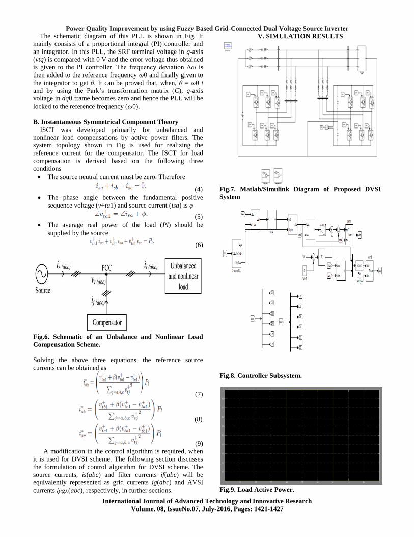
V. SIMULATION RESULTS
Fig.7. Matlab/Simulink Diagram of Proposed DVSI
System
Fig.8. Controller Subsystem.
Fig.9. Load Active Power.
P. MALLIKARJUN, S. KARUNAKAR
International Journal of Advanced Technology and Innovative Research
Volume. 08, IssueNo.07, July-2016, Pages: 1421-1427
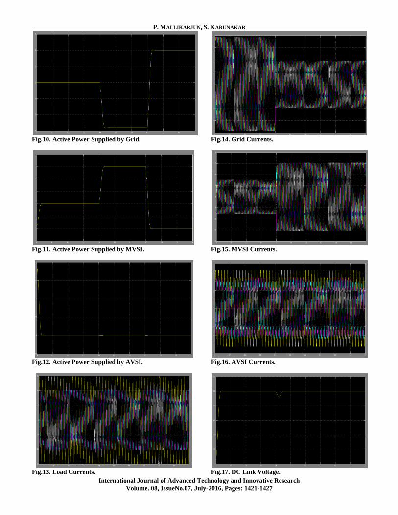
Fig.10. Active Power Supplied by Grid.
Fig.11. Active Power Supplied by MVSI.
Fig.12. Active Power Supplied by AVSI.
Fig.13. Load Currents.
Fig.14. Grid Currents.
Fig.15. MVSI Currents.
Fig.16. AVSI Currents.
Fig.17. DC Link Voltage.

Power Quality Improvement by using Fuzzy Based Grid-Connected Dual Voltage Source Inverter
International Journal of Advanced Technology and Innovative Research
Volume. 08, IssueNo.07, July-2016, Pages: 1421-1427
VI. CONCLUSION
The proposed DVSI is Control algorithms are developed to
generate reference currents for DVSI using ISCT. The
proposed scheme has the capability to exchange power from
distributed generators (DGs) and also to compensate the local
unbalanced and nonlinear load. The performance of the
proposed scheme has been validated through simulation and
experimental studies. As compared to a single inverter with
multifunctional capabilities, a DVSI has many advantages
such as, increased reliability, lower cost due to the reduction
in filter size, and more utilization of inverter capacity to inject
real power from DGs to microgrid. Moreover, the use of
three-phase, threewire topology for the main inverter reduces
the dc-link voltage requirement. Thus, a DVSI scheme is a
suitable interfacing option for microgrid supplying sensitive
loads. Simulation results are observed for a proposed fuzzy
based DVSI.
VII. REFERENCES
[1]Y. Zhang, N. Gatsis, and G. Giannakis, ―Robust energy
management for microgrids with high-penetration
renewables,‖ IEEE Trans. Sustain.Energy, vol. 4, no. 4, pp.
944–953, Oct. 2013.
[2]R. Majumder, A. Ghosh, G. Ledwich, and F. Zare, ―Load
sharing and power quality enhanced operation of a distributed
microgrid,‖ IET Renewable Power Gener., vol. 3, no. 2, pp.
109–119, Jun. 2009.
[3]J. Guerrero, P. C. Loh, T.-L. Lee, and M. Chandorkar,
―Advanced control architectures for intelligent microgrids—
Part II: Power quality, energy storage, and ac/dc microgrids,‖
IEEE Trans. Ind. Electron., vol. 60, no. 4,pp. 1263–1270, Dec.
2013.
[4]Y. Li, D. Vilathgamuwa, and P. C. Loh, ―Microgrid power
quality enhancement using a three-phase four-wire grid-
interfacing compensator,‖ IEEE Trans. Ind. Appl., vol. 41, no.
6, pp. 1707–1719, Nov. 2005.
[5]M. Schonardie, R. Coelho, R. Schweitzer, and D. Martins,
―Control of the active and reactive power using dq0
transformation in a three-phase grid-connected PV system,‖ in
Proc. IEEE Int. Symp. Ind. Electron., May 2012, pp. 264–269.
[6]R. S. Bajpai and R. Gupta, ―Voltage and power flow
control of grid connected wind generation system using
DSTATCOM,‖ in Proc. IEEE Power Energy Soc. Gen.
Meeting—Convers. Del. Elect. Energy 21st Century, Jul.
2008, pp. 1–6.
[7]M. Singh, V. Khadkikar, A. Chandra, and R. Varma, ―Grid
interconnection of renewable energy sources at the
distribution level with power-quality improvement features,‖
IEEE Trans. Power Del., vol. 26, no. 1, pp. 307–315, Jan.
2011.
[8]H.-G. Yeh, D. Gayme, and S. Low, ―Adaptive VAR
control for distribution circuits with photovoltaic generators,‖
IEEE Trans. Power Syst., vol. 27, no. 3, pp. 1656–1663, Aug.
2012.
[9]C. Demoulias, ―A new simple analytical method for
calculating the optimum inverter size in grid-connected PV
plants,‖ Electr. Power Syst. Res., vol. 80, no. 10, pp. 1197–
1204, 2010.
[10]R. Tonkoski, D. Turcotte, and T. H. M. EL-Fouly,
―Impact of high PV penetration on voltage profiles in
residential neighborhoods,‖ IEEE Trans. Sustain. Energy,
vol. 3, no. 3, pp. 518–527, Jul. 2012.
[11]P. Rodriguez et al., ―A stationary reference frame grid
synchronization system for three-phase grid-connected
power converters under adverse grid conditions,‖ IEEE
Trans. Power Electron., vol. 27, no. 1, pp. 99–112, Jan.
2012.
[12]S. Iyer, A. Ghosh, and A. Joshi, ―Inverter topologies
for DSTATCOM applications—A simulation study,‖
Electr. Power Syst. Res., vol. 75, no. 23, pp. 161–170,
2005.
[13]Y. Tang, P. C. Loh, P. Wang, F. H. Choo, and F. Gao,
―Exploring inherent damping characteristic of LCL filters
for three-phase grid-connected voltage source inverters,‖
IEEE Trans. Power Electron., vol. 27, no. 3, pp. 1433–
1443, Mar. 2012.
Author Profile:
Perne Mallikarjun has received his
B.Tech degree in Electrical & Electronics
Engineering from Prasad engineering
college, shameerpet, jangaon, Warangal in
2014 and M.Tech in Power Electronics
from Prasad Engineering College,
Shameerpet, Jangaon, Warangal in 2016 Telangana, India.
![POWER QUALITY ENHANCEMENT USING FUZZY CONTROL … · Power Systems Quality, McGraw-Hill, NewYork, NY,USA, 2nd edition, 2006. [2] N.G. Hingorani and L Gyugyi, “Understanding FACTS](https://img.pdfslide.us/doc/110x75/5fc3c0dada499440d33d8bb9/power-quality-enhancement-using-fuzzy-control-power-systems-quality-mcgraw-hill.jpg)


![PERFORMANCE OF DVR AND IDVR FOR VOLTAGE ...Power Quality Improvement Using Multi -Level Inverter Based DVR and DSTATCOM Using Neuro -Fuzzy Controller. [3] Power Quality Improvement](https://img.pdfslide.us/doc/110x75/5ed31f7b2c1fe74f476f3361/performance-of-dvr-and-idvr-for-voltage-power-quality-improvement-using-multi.jpg)