Embed Size (px)
Citation preview
technology
4RUD A :L BLA ET I : DGI ED S : I GC NI
MAN Y
D
ProDigital RoHScompliant www.sterling-power.com
STERLINGPOWER PRODUCTS
e13
Pro Split R

This unit assumes a common negative between all battery banks and alternators. The unit is is to prevent any short circuit when running the new cables, a short circuit on a battery can designed so that the alternator and starter battery are in contact when the engine is off, this is to easily cause a fire or the battery in question could explode. If in doubt, please employ a ensure that when the engine starts up if you have an alternator which needs a voltage on the professional electrician to install the unit. Or, contact Sterling power products on help@sterling-alternator to fire it up then the starter battery connection will supply that voltage. When the engine power.com or see our web site www.sterling-power.com & www.sterling-power-usa.com.is started and the alternator fires up the system maintains the connection with the starter battery Always work from the unit to the battery bank. I.e. fit the cables onto the unit then the fuse then until this battery exceeds about 13.3 volts ( ), this could be a few minutes or a few connect them to the battery as this way is much safer than connecting cables to the batteries seconds. The system then checks battery bank 2 to ensure that it is ok and does not have a short then connecting to the unit.circuit on it, it then engages battery bank 2 and keeps the starter battery and battery bank 2 online It is recommended to place fuses as close to the batteries as possible, also, fit them first until they both reach 13.3 volts, (again this could take a few minutes or a few seconds depending on as they can protect against any accidents during installation. The fuses are there to protect the the state and size of the battery bank) the system then checks battery bank 3 ( in a 3 output unit ) cables in the event of the positive cable coming in contact with the chassis of a vehicle or a steel and then engages battery bank three. This process could take as little as 3 seconds under normal hull on a narrow boat or a bonding system on a boat or vehicle. In some case this is a statuary conditions or in extreme cases with large flat batteries up to an hour or so. The unit continues to requirement. monitor the voltages on the 3 outputs and the alternator input, in theory these should all be the Fuses are not supplied with the unit but can be purchased separate from your local chandlery or same, any attempt to pull these voltages below 13 volts means that one battery bank is attempting to from Sterling Power Products. For high current fuses Sterling always recommends fuses to be discharge in excess of the ability of the alternator to supply the current and is going to start off start installed at about 50% larger than the maximum possible current, round this figure up to the taking power from one of its neighbouring battery banks, in the event of this happening the system nearest 50 amps.will channel the alternator power into the battery bank which requires this load, and disconnect and protect the other battery banks.
I would advise you read what all the alarm functions do , this may make understanding the system easier.To install the unit, pick a cool part of the engine room ( i.e. as low as possible ) the unit is to. It also does not matter what way up the unit goes. However, the unit has been designed so the cables do not run across the bolts from other battery banks, if the unit is connected, as per the
Please note that the unit will not switch off as soon as you switch off the engine, obvious writing on the unit and the cables should be brought up from below. You can connect when the engine is switched off the battery banks will be isolated but the unit LEDs will remain on the unit at any angle you wish to assist in the wiring process. Using the 4 fixing holes firmly for about 10 seconds or so. secure to a bulkhead. When all cables are connected tie and secure the cables in such a way as
A special connection is there weight is supported on the bulkhead and they do not vibrate or touch any of the other available on the unit for advanced regulators and remote sensors on alternators with battery sensed studs.regulators (Volvo), we strongly recommend you use this point, this is to ensure the maximum Ensure your alternator(s) is working within the total limits of the unit. I.e. if the unit is 180A the performance of the alternator and compensates for any voltage drop between the alternator and this total maximum current is 180A, it does not matter if this is a 50A alternator plus a 70A control box . alternator as the total possible current does not exceed the continuous rating. For a twin
alternator input, each output can deal with the total from both alternator’s output together. I.e a Under normal running conditions twin 130 alt unit can handle the full charge of 260 amps out of any of the outputs.
with the alternator working then all these LEDs should be on, these LEDs show that the circuit is Fit in a position to minimize the length of cables used, the shorter the cables the better. Look at active. In the event of one LED being off then look below on the red trip warning LEDs to find out the cable chart below for recommended cable size, larger cables are usually hard to come by so why that circuit has been disconnected. if, for example, you want 200A cable, but only have 50 amp cable then simple run 4 lengths of 1 ) in the event of the alternator voltage exceeding 50 amp cable as all you are doing is running is copper. 16 volts (x2 for 24V system), the unit will disconnect all battery banks from the batteries (all the Try to connect where possible the engine starter battery to the battery terminal marked starter, blue LEDs showing connection to each battery bank will be off and this alarm LED will be this connection is recommenced but not the end of the world if not possible. There is no life flashing) this will protect the batteries from excessive damage and allow you to continue on your threatening danger involved if this is not used on the starter battery, the only reason for this is journey without the worry of exploding batteries and have the alternator regulator repaired at your we take a special feed from this engine start battery to ensure the alternator will ''fire up '’ so we next destination: in the event of the alternator voltage dropping down to below 15V for whatever want to ensure there is life in this battery in order to fire up the alternator, our design reason (I.e. if the advanced regulator was a Sterling and it also picked up the high voltage fault, the assumption is if this battery is dead you cannot start the engine so the unit would not work advanced reg would return the alternator’s regulator control back to the original reg which may be anyway. However, if the battery is dead and you jump start the engine then we will have the ok) during the journey then the unit would reset and continue to charge the battery banks. power required to fire up the engine alternator so all the batteries can then be recharged. Failure 2 this is where 16 volts (32 volts) is sensed on one of to have any power in this battery bank might prevent your alternator from firing up and so the the battery bank inputs, this could come from something for example a defective battery charger on unit might not work correctly (not that it would matter anyway if the alternator is not working). battery bank 3 trying to backfeed the dangerous voltage back into the other battery banks. The unit will identify the offending battery bank and isolate battery banks to prevent damage to the rest of Negative connection. The negative connection is simply a feed for the internal electronics, this the system (this will result in any damage which might be caused by the defective bank being actual current in this cable would not exceed 2A, so a normal 5-10A cable would be more than limited to that bank and not causing damage to the other battery banks) however, we are unable to enough for this connection. The negative should go to a negative on the main battery bank prevent the damage being caused to the actual battery bank causing the problem. For this, look at common neg or any other good local negative source.our new range of voltage sensitive current limiting relays. this is a D/C feed from an ignition source, I.e. from the d+ / 61/ L/ on the back of 3 ) this is where there has been an attempt by one battery bank to an alternator or a feed direct from the ignition key switch. Or, anything which becomes live discharge the others, for example, if there was a high power inverter (3000 watts) on the domestic when the engine is working and is off when the engine stops. This simply tells the unit that the battery bank and the battery was very low, if someone, for example, put on the kettle then the engine is on or off.inverter would attempt to pull 200 amps from the other battery banks, in this event the unit would When the engine is started then the ignition feed sense this and ensure the other battery banks would be disengaged and the alternator path directed should become live activating the unit, expect to see at least 1 LED come on. The unit then goes to the inverter bank only, until such time as the high load was discontinued and the battery bank through a test sequence, checking each battery bank to see if everything is okay. Then the unit allowed to come up to 13.3 volts, then the other banks would come back online and the battery starts with the engine start battery and charges it until it exceeds 13.3 volts, this could take 10 chargers accordingly, as per the explained start up sequence. If the engine battery safety voltage seconds or 10 minutes. It will then switch on battery bank 2 along with the starter battery and limit was reached this would disconnect all batteries and direct the power to the engine start start to charge it until both reach at least 13.3V, then battery bank 3 will be connected. With all 4 ) , if this LED is flashing then the alternator (or battery charger) is outputs now working the system will continue to charge all battery banks (in normal below 13.3V ( 26.6V for 24V etc), this is usual and would only happen if the cable between the circumstances this would be all the unit needed to do) alternator and the unit is too thin or too long for the amount of current, or, there is a high drain from The system continues to monitor all outputs and inputs. In the event of any attempt to reverse one battery bank. If LED off at below 10V ( which means it’s not working. If LED is on solid then feed from one battery bank, the bank which is attempting the reverse feed (the one with the voltage over 13.3V and working ok heaviest load, i.e. an anchor winch or a large inverter could have been turned on) will be kept 5 ) LED on means the unit is working normally, flashing blue LED means online with the alternator in order to supply the max current to this demand source and the other that the alternator is off ( or not working ). The unit is in standby mode. battery banks will be isolated to prevent power loss from those battery banks, this isolation will 6 ) Negative stud, This is the device control negative, a simple 10 amp cable is more than enough to remain until such time as the battery bank in question has come up to about 13.3V (or the run the device, this must be connected to the common negative of the batteries. priority engine start battery falls below 12.4V) before engaging the rest of the battery banks. 7 ) Battery sense connection, this is where we recommend that you place the remote sense wire When the engine is switched off the unit shuts down after 10 seconds and uses no power.from an advanced alternator regulator or a battery sensed alternator, it ensures that the regulator is two or more alternator can be connected to the alternator input always charging all battery banks the same and prevents any over charge of any batteries, if there is position, this can either be 2 alternators from one engine or 2 alternators on different engines.no advanced reg or battery sensed regulator being used with the alternator then do not worry about . This is a special design for most motor this connection. boats fitted with a twin engines ( i.e. twin Merc, Volvo, Yanmar) they tend to come with about 8) Auxiliary battery banks 2 and 3 ( on a 2 output unit there will only be one aux battery bank ) 110A alternators fitted to each engine. In conventional boat installations a lot of potential these connect to the battery banks other than the starter battery of the engine which the alternator is power from these alternators are not effectively unitized, with power being wasted, with each connected to. alternator charging a limited number of the total banks on the vessel and not effectively 9 ) Alternator input, this is the main alternator input cable, it could also be used for a battery channeling power from both alternators to where the max power is required . charger, or the output of an alternator to battery charger etc to increase the number of battery banks This unit can be used for lots of other functions due to its 0.0 voltage drop across it. you wish to charge. It can split the outputs from any power source and distribute this power to different battery 10 ) This connection is recommenced to be used by the engine starter battery. There is no life banks, i.e. you may have one of our battery to battery chargers (which have a single output ) or threatening danger involved if this is not used on the starter battery, the only reason for this is that an alternator to battery charger (again with a single boosted output) and you wish to charge the design takes a special feed from this engine start battery to ensure the alternator will ''fire up '' more than one battery bank, then, simply connect the power to the alt position and the unit will so we want to ensure there is life in this battery in order to fire up the alternator, our design split accordingly.assumption is if this battery is dead you cannot start the engine so the unit would not work anyway, : Obviously under normal running functions there should be no alarms, however, if the battery is dead and you jump start the engine then we will have the power required however, things do go wrong, with any safety system there has always got to be a balance to fire up this unit and the engine alternator so all the batteries can re-charge. Failure to have any between safety and the safety system causing more problems than it protects. With some alarms power in this battery bank ( i.e a flat battery, the alternator may not ''fire up''.) this is obvious the safety alarm switches everything off. However, safety functions such as 11 ) Ignition feed: connect direct to an ignition feed or to the back of the alternator to the D+/61/L engine priority system which ensures the engine start battery is ok is a bit more complex. This terminal, i.e. any feed which becomes live when the engine is running and goes off when it stops. alarm function has a timer involved which increases every time the alarm is engaged in each This simply informs the unit the engine should be working and to start. session, i.e the first alarm locks the engine battery online for 1 min then it resets to feed the
other batteries, if the alarm happens again then the time is increased to 2 minutes on the engine start battery, then, if the other batteries come back online, if the alarm happens again the time is then 3 minutes etc. If this alarm happens alot then the bottom line is your alternator system is not capable of keeping up with your demand and should be up rated or an extra alternator fitted. The Pro Split’s priority is to ensure the starting of your engine.
The actual installation of this device is very straight forward, the instructions are shown with a 1 in 3 out 180 amp unit and a 2 alt in 4 battery bank out. However, a 2 output unit only has 2 outputs but connects up the same with the obvious 1 less output.Before starting this installation, disconnect the negative and positive cables from the batteries, this
x 2 for 24V
Fuses.
It will, however, continue to monitor the starter battery as the most important bank and in this event, at any stage of the starter battery dropping below 12.6 volts ( x 2 for 24v ) then all battery banks will be disengaged and all power will be diverted into the starter battery bank until it comes up to 13.3V. Then it will repeat the start up process. This would be a very unlikely situation but is a fail safe built into the software to guarantee the engine start battery above all others.
High alternator voltage trip. (red LED flashing)
High output voltage trip. (red LED on solid)
Ignition feed:Back feed engaged (red LED on)
How does the unit work, and what to expect.
Trip/Alarm sequence
Other uses for this product.Use with a single output battery charger to give multiple output charger or use with Sterling Battery to Battery charger to give extra outputs etc. For maximum performance from your alternator this unit should be used in conjunction with a
Installation:
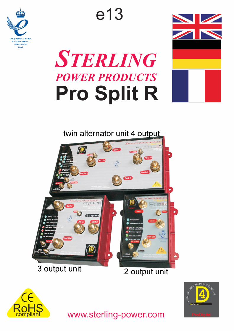
Please note in the event of any outputs on the pro split not being used then they must be linked to one which is, i.e. all outputs must be used, one must not be left unconnected.
Sterling Power Products has a full range of high current fuses from 100-500 amps, the part number is GANLR for the fuse holder and GANL100 for a 100 amp fuse andGANL200 for a 200 amp fuse etc.
Unit switching off.
Advanced alternator regulators or alternators with battery sense regulators.
L.E.D. information on the front of the unit Starter battery / battery 2, battery 3, starter 2, online (blue LEDs).
On ok ( LED Blue on )
Twin alternator installation:
Other uses.
Sterling Advanced Digital Alternator regulator / Alternator to battery charger / Battery to battery charger
Always remember that if you wish to boost the performance of your system, look at the Sterling Advanced alternator regulators or the battery to battery chargers .
)
Alternator power rail state
Twin engine, twin alternator, isolated, 4 output unit
ProSplit R - Functions + Installation
UL : D RA AITG BI LED : :DC I
EM SA IN G
NYD
Alt in
Start Batt
Batt 3
Batt 2
Negative
Sence
Engine start battery Main domestic battery bank Bow Thruster/ gen/ second eng/etc
enginestarter motor
1 or 2 alternators
Advanced alternatorregulator.or alternator battery sensedregulator if fitted toalternator
fuse
fuse
fuse
Fuse holderGANLR
fuse100-500 amps
++
++ignition feed
alternatord+ or
ignition feed
Single enginetwin engine ( non isolated )
twin alternator3 battery bank
or or
plus UNIVERSAL ADVANCED DIGITAL+ 4 STEP ALTERNATOR REGULATOR
GREEN: HIGH CHARGE RATE ON
YELLOW: TIMER ACTIVATED
RED ONLY : HIGH BATTERY V TRIP FLASHING RED: HIGH BATTERY TEMP
HELP LINE FOR STERLING POWER PRODUCTS TEL U.K 01905 26166
GREEN: FLOAT MODE
ORANGE: LOW VOLTAGE WARNING
BATTERY TYPE: GREEN: GEL/SEALED YELLOW: OPEN LEAD ACID RED: A.G.I.
1 2
ON
1 2
ON
1 2
ONBATTERY TYPE
PROGRAM SELECTORSWITCH, INSIDE LID
3 BATTERY TYPE POSITIONS GEL
SEALEDL.E.D.
( GREEN )
LEADOPENL.E.D.
( YELLOW )
A.G.ML.E.D.( RED )
ALL L.E.D.SFLASHING
HIGH ALTERNATOR
VOLTAGE TRIP
BATTERY NEG TRIP FAULT
GREEN:HIGH ALT TEMP DISENGAGE
YELLOW:12 V SYSTEM SETUP
GREEN: 24 V SYSTEM SETUP
ALTTEMP
BATTERYTEMP
D+SWITCH
EXTRACONNECTIONS
BLOCK
REMOTECONTROLSOCKET
TERLING POWER PRODUCTSS
fan
t
UNIVERSAL ADVANCED DIGITAL+ 4 STEP ALTERNATOR REGULATOR
GREEN: HIGH CHARGE RATE ON
YELLOW: TIMER ACTIVATED
RED ONLY : HIGH BATTERY V TRIP FLASHING RED: HIGH BATTERY TEMP
HELP LINE FOR STERLING POWER PRODUCTS TEL U.K 01905 26166
GREEN: FLOAT MODE
ORANGE: LOW VOLTAGE WARNING
BATTERY TYPE: GREEN: GEL/SEALED YELLOW: OPEN LEAD ACID RED: A.G.I.
1 2
ON
1 2
ON
1 2
ONBATTERY TYPE
PROGRAM SELECTORSWITCH, INSIDE LID
3 BATTERY TYPE POSITIONS GEL
SEALEDL.E.D.
( GREEN )
LEADOPENL.E.D.
( YELLOW )
A.G.ML.E.D.( RED )
ALL L.E.D.SFLASHING
HIGH ALTERNATOR
VOLTAGE TRIP
BATTERY NEG TRIP FAULT
GREEN:HIGH ALT TEMP DISENGAGE
YELLOW:12 V SYSTEM SETUP
GREEN: 24 V SYSTEM SETUP
ALTTEMP
BATTERYTEMP
D+SWITCH
EXTRACONNECTIONS
BLOCK
REMOTECONTROLSOCKET
TERLING POWER PRODUCTSS
fan
t
STERLING POWER PRODUCTS
Advanced Intelligent digital
0.0 volt drop alternator distribution system
STERLING POWER PRODUCTS
www.sterling-power.com
technology
4 U: D RL AAT BI
G LI ED : : D
CI ESM IA G
NNYD
ProDigital
Alt in
Start Batt
Batt 3
12 v systemBattery 3 / on line
Battery 2 / on line
Start Battery/on line
High alt voltage trip ( flashing )High output voltage trip ( solid )
Back feed engaged
Flash alt below 13.3 v/ on alt above 13.3 volts
On ok/Flash stand buy
RoHScompliant
Batt 2
Sence
Pro Split R 180
Negative
Pos Ign feed
7
8
9
10
2
3
4
5
{1
6
11
WHAT CABLE TO USE in mm sq:A charger or inverter cable run distance cable run distance
0-25 A 6 mm2 10 mm2
25-45 A 16 mm2 25 mm2
45-85 A 25 mm2 35 mm2
85-125 A 35 mm2 50 mm2
125-180 A 50 mm2 70 mm2
180-330 A 70 mm2 90 mm2 Please note that if there is a problem obtaining for example 90 mm sq cable, simply use 2 x 50 mm2 , or 3 x 35 mm2 , the cable is simply copper, and all you require is the copper , it does not matter if it is one cable or 10 cables as long as the square area adds up. Performance of any product can be improved by thicker cable, so if in doubt round it up.
up to 0 - 1.5m 1.5 – 4.0m
UL : D RA AITG BI LED : :
DC I
EM SA IN G
NYD
Alt in
Start Batt
Batt 3
Batt 2
Negative
Sence
Engine start battery Main domestic battery bank Bow Thruster/ gen/ second eng/etc
enginestarter motor
1 or 2 alternators
fuse
fuse
ufse
Fuse holderGANLR
fuse100-500 amps
++
++ignition feed
alternatord+ or
ignition feed
Used in conjunction with a
giving mutable boosted outputs from the
single boosted output unit
Alternator to battery charger
Alternator to battery charger
Boostedoutput
Boostedoutput
UL : D RA AITG BI LED : :
DC I
EM SA IN G
NYD
Alt in
Start Batt
Batt 3
Batt 2
Negative
Sence
+
+ignition feed
Boostedoutput
Engine start battery Main domestic battery bank Bow Thruster/ gen/ second eng/etc
engine
starter motor
1 or 2 alternators
fuse
uf se
fuse
+
+
alternatord+ or
ignition feed
Batt 3
Batt 4Negative
Alternator 1 2
Alt 2 Ign feed
Alt 1 in Alt 2 in
Start Batt 1
Start Batt 2
Alt 1 Sence Alt 2 Sence
+
+
+
+Alt 1 Ign feed
Main domestic battery bank Bow Thruster gen
sfue
fuse
Engine start battery
Engine start battery
enginestarter motor
alternator
engine
starter motor
alternator
Advanced alternatorregulator.or alternator battery sensedregulator if fitted toalternator
Advanced alternatorregulator.or alternator battery sensedregulator if fitted toalternator
Twin engine, 4 battery bank
UNIVERSAL ADVANCED DIGITAL+ 4 STEP ALTERNATOR REGULATOR
GREEN: HIGH CHARGE RATE ON
YELLOW: TIMER ACTIVATED
RED ONLY : HIGH BATTERY V TRIP FLASHING RED: HIGH BATTERY TEMP
HELP LINE FOR STERLING POWER PRODUCTS TEL U.K 01905 26166
GREEN: FLOAT MODE
ORANGE: LOW VOLTAGE WARNING
BATTERY TYPE: GREEN: GEL/SEALED YELLOW: OPEN LEAD ACID RED: A.G.I.
1 2
ON
1 2
ON
1 2
ONBATTERY TYPE
PROGRAM SELECTORSWITCH, INSIDE LID
3 BATTERY TYPE POSITIONS GEL
SEALEDL.E.D.
( GREEN )
LEADOPENL.E.D.
( YELLOW )
A.G.ML.E.D.( RED )
ALL L.E.D.SFLASHING
HIGH ALTERNATOR
VOLTAGE TRIP
BATTERY NEG TRIP FAULT
GREEN:HIGH ALT TEMP DISENGAGE
YELLOW:12 V SYSTEM SETUP
GREEN: 24 V SYSTEM SETUP
ALTTEMP
BATTERYTEMP
D+SWITCH
EXTRACONNECTIONS
BLOCK
REMOTECONTROLSOCKET
TERLING POWER PRODUCTSS
fan
t
alternatord+ or
ignition feedon alt 2
alternatord+ or
ignition feedon alt 1
fuse
sefu
fuse
u ef s
Please note in the event of any outputs on the pro split not being used then they must be linked to one which is, i.e. all outputs must be used, one must not be left unconnected.
Used in conjunction with a
giving mutable boosted outputs from the
Battery to battery charger
Battery to battery charger
ProSplit R - Layout and diagram

FUNKTIONEN INSTALLATIONBeim PROSPLIT sind die Starterbatterie und die Lichtmaschine miteinander verbunden, damit beim Starten Die Installation des Gerätes ist einfach. Das Beispiel zeigt die Verkabelung anhand eines (1 Eingang, 3 eine Spannung an der Lima ist, falls dieses benötigt wird. Nach dem Start wird zuerst die Starterbatterie geladen Ausgang, 180 Ampere) PROSPLIT 180. Die Version mit 2 Ausgängen wird auf die selbe Art verkabelt.
Vor Beginn der Installation trennen Sie +(PLUS) und -(MINUS) Kabel von den Batterien. So verhindern und sobald 13,3V erreicht sind (normalerweise innerhalb von wenigen Sekunden), wird die 2. Batterie Sie einen Kurzschluss beim Verlegen. Bei einem Kurzschluss an einer Batterie besteht sogar Brand- hinzugeschaltet. Ist die 2. Batterie sehr leer, dann wird die Starterbatterie kurzfristig getrennt, um eine und/oder Explosionsgefahr. Wenn Sie keine Erfahrung haben, beauftragen Sie bitte eine Entladung der Starterbatterie zu verhindern. Wird die Starterbatterie getrennt, dann wird diese, sobald 13,3V Elektroinstallationsfirma mit dem Einbau.erreicht werden, sofort wieder dazugeschaltet.Beginnen Sie die Verkabelung immer vom PROSPLIT beginnend, hin zur Batteriebank und befestigen Erreichen dann beide Batterien mindestens 13,3V, wird die 3. Batterie(-bank) dazugeschaltet. Hier wieder der Sie sämtliche Kabel zusätzlich mit Kabelschellen an der Montagefläche (Wand, Spanten etc.) um das gleiche Vorgang. Ist die Batterie(-bank) 3 sehr leer, dann werden die Starterbatterie und die Batterie(-bank) 2 Gewicht der Kabel vom PROSPLIT zu nehmen. getrennt und es wird nur die Batterie(-bank) 3 geladen. Sobald 13,3V erreicht sind, werden wieder die anderen
Batterie(-bänke) dazugeschaltet.Sicherungen (http://shop.sterling-power.com)Anschließend werden alle angeschlossenen Batterien bis zur maximalen Ladeschlussspannung geladen und Schließen Sie als Erstes bitte die Sicherungen so nahe der Batterien wie möglich annur in besonderen Situationen oder beim Abschalten des Motors wieder voneinander getrennt.
Es gibt 3 Gründe weshalb Sicherungen unerlässlich sind:Der PROSPLIT überwacht kontinuierlich die Spannungen auf den 3 Batterie(-bank)anschlüssen und dem 1 Sicherungen schützen uns vor etwaigen Unfällen während der Installation.Lichtmaschineneingang. Theoretisch sollten alle Anschlüsse die gleiche Spannung aufweisen. Fällt die 2 Sie schützen die Kabel für den Fall des Kontaktes mit dem Chassis eines Fahrzeuges, der metallenen Spannung unter 13V, dann wird mehr verbraucht, als die Lichtmaschine imstande ist zu liefern. In diesem Fall Bootshülle eines Narrowboats oder der Verbundhülle eines Motorboots.trennt der PROSPLIT die Batterie(-bänke), welche entladen werden könnten und der gesamte Strom der 3 Sollte ein Kurzschluss an einer Batterie auftreten, macht es Sinn die Sicherung zu zerstören um die Lichtmaschine wird in die Batterie(-bank) geleitet, welche den höchsten Bedarf hat. Nur so ist sichergestellt, Batterie vom Netz zu trennen und dadurch PROSPLIT zu schützendass die anderen Batterien nicht entladen werden. Sicherungen sind nicht im Lieferumfang der Einheit enthalten, können aber von ihrem Händler oder Prioriät der Starterbatterie: Die Starterbatterie wird ständig überwacht um sicherzustellen, dass die Spannung direkt von STERLING POWER (http://shop.sterling-power.com) bezogen werden. Die Anforderungen nicht unter 12,4V sinkt. Fällt die Spannung an der Starterbatterie unter 12,4V, dann werden die anderen an Sicherungen variieren von Land zu Land und von Standard zu Standard. Aus diesem Grund obliegt es Batterie(-bänke) von der Lichtmaschine getrennt und die Starterbatterie wird auf mindestens 13,3V geladen, Ihnen, die passenden Sicherungen für den jeweiligen Zweck auswählen. STERLING POWER empfiehlt bis die anderen Batterie(-bänke) wieder dazugeschaltet werden.Ihnen Sicherungen zu wählen die ca. 30% stärker sind als die höchste zu erwartende Stromstärke. Runden Sie diese Rechnung auf den nächsten 50 Ampere Schritt auf.Das PROSPLIT schaltet erst ca. 20 Sekunden, nachdem der Motor abgeschaltet wurde, aus. Davor werden STERLING POWER bietet die gesamte Bandbreite an Sicherungen (100-500 Ampere). Die jedoch die Batterien voneinander getrennt, damit keine Entladung stattfinden kann.Sicherungshalterung hat die Art.no. “GANLR”, eine 100 Ampere Sicherung hat die Art.no. “GANL100”, eine 200 A die Art.no. “GANL200” etc.Haben Sie einen Hochleistungsregler oder ein Sensorkabel des eingebauten Reglers, so muss dieses Es wird außerdem dringend empfohlen sich in der Bedienungsanleitung über alle Alarmfunktionen zu Sensorkabel auf den Anschluß am PROSPLIT gelegt werden, damit es nicht zu einer Überladung kommen informieren.kann.Wählen Sie einen möglichst kühlen Bereich. Wählen Sie einen Bereich an dem die Kabel vom Gerät zu den Batterien möglichst kurz sind. Das Gerät ist wasserdicht und somit unempfindlich gegen Die folgenden Nummern repräsentieren die entsprechenden Beschreibungen zu den jeweiligen Punkten in der Spritzwasser. Verwenden Sie die 4 Montagelöcher und befestigen Sie es sicher an einem Bugschott, Ansichtsgrafik (PROSPLIT)Rumpfspant oder an sonst einer geeigneten Montagefläche. Vergewissern Sie sich das Ihre Lichtmaschine(n) innerhalb der Grenzwerte des PROSPLIT laufen. Beim 1 Starterbatterie / Batterie 2 / Batterie 3 on line - blaue LEDs180 Ampere-Gerät nicht mehr als 180 Ampere maximaler Stromstärke zuführen. Dabei ist egal wie Sie Unter normalen Umständen sollten alle drei LEDs leuchten. Wenn die Batterien sehr leer sind, kann dieses diese Leistung erreichen, ob 50A LM und 80A LM und 40A Ladegerät und 10A WIND GEN, solange der etwas dauern. Mindestens 1 LED sollte allerdings leuchten.max. Wert eingehalten wird. Sehen Sie in der Kabeltabelle nach um die entsprechend empfohlenen
2 Überspannung der Lichtmaschine - rote LED blinkend: Kabelstärken nachzulesen. Sie können anstatt eines 200 Ampere Kabels auch 4 Längen eines 50 Ampere Bei Überspannung der Lichtmaschine > 16V (12V System) oder > 32V (bei einem 24V System) werden die Kabels verwenden.Batteriebänke automatisch von der Lichtmaschine getrennt und die blauen LEDs hören zu leuchten auf. Diese Dabei gilt: Es darf nur Kupferkabel verwendet werden.Funktion schützt die Batterien vor Schaden. Die Funktion der Lichtmaschine sollte allerdings schnellstens Versuchen Sie, falls möglich, die Starterbatterie an den dafür vorgesehenen Anschluss am PROSPLIT überprüft werden. Eventuell könnte es auch vorkommen, dass noch ein Sensorkabel des anzuschliessen. Sollte dies bei Ihrer Installation nicht möglich sein, so ist das auch kein Problem. Bei Lichtmaschinenreglers direkt an einer der Batterien angeschlossen ist und nicht am dafür vorhandenen Lichtmaschinen, welche eine Spannung an B+ benötigen, um die Ladung zu starten, muss eine Batterie an Anschluß des PROSPLIT. den Anschluß “STARTER” angeschlossen werden.AN: Wenn an einem der Batterieausgänge mehr als 16V (32V) auftreten, dann wird nur dieser Anschluss
Unser Design-Gedanke ist dabei folgender: Wenn die Starterbatterie leer ist kann man den Motor nicht getrennt. Dadurch wird verhindert, dass die anderen Batterien auch überladen werden. Die Ursache könnte ein starten und PROSPLIT würde nicht laufen können. Angenommen die Batterie ist leer und Sie starten den defektes Ladegerät, Windgenerator oder eine Solarzelle sein.Motor durch Starter-Hilfe, dann passiert folgendes: PROSPLIT und die Lichtmaschine schalten sich ein
3 Entladungs-Schutz - rote LED da nun die benötigte Energie vorhanden ist, können auch die restlichen Batteriebänke wieder aufgeladen Wenn eine sehr hohe Last an einer Batterie(-bank) hängt (z.B. Wechselrichter, Ankerwinsch, Bugstrahlruder werden können.o.ä.), und die Lichtmaschine die benötigte Leistung nicht zur Verfügung stellen kann, dann kann es dazu Negativanschlusskommen, dass Ladung von den anderen Batterien abfließt. Um das zu verhindern werden die vollen, Der Negativanschluss dient als Einspeisung für die interne Elektronik. Die Stromstärke in diesem Kabel unbelasteten Batterien abgeschaltet, so dass die Ladung der Lichtmaschine direkt an die Batterie geleitet wird, ist nicht höher als 2 Ampere. Ein normales 10 Ampere Kabel ist absolut ausreichend für diese Verbindung. welche die maximale Ladung benötigt. Vom Negativ des PROSPLIT zu einem Negativ an der Hauptbatteriebank oder jegliche andere Die anderen Batterie(-bänke) werden erst dann wieder zugeschaltet, sobald mindestens 13,3V erreicht sind. ausreichende Negativquelle, solange sie nur nah der Batterien liegt.
Zündungseinspeisung4 Lichtmaschinen Spannung - grüne LED Das ist eine DC Einspeisung von einer Zündungsquelle (z.B. Vom d+/61/L an der Rückseite der AUS: Spannung der Lima (und auch eventuell der Starterbatterie) liegt unter 10V. Eventuell ist die Lichtmaschine oder einer Einspeisung vom Zündungsschalter)Lichtmaschine defekt. Wie die Einheit funktioniert und was Sie erwarten können.Blinkend: Spannung der Lima ist unter 13,3V. Ändert sich dieser Zustand auch nach Stunden nicht, dann ist Wenn der Motor abgestellt wird fährt die Einheit nach 15 min herunter ohne weitere Energie zu entweder die Lichtmaschine zu klein oder die Lichtmaschine ist defekt. verbrauchen. Wird der Motor gestartet, so beginnt auch die Zündungseinspeisung, welche somit die AN: Spannung an der Lima ist > 13,3V (26,6V). Alles OK. Einheit startet. Es sollte zumindest ein LED zu leuchten beginnen wenn die Lichtmaschine 13 Volt
Spannung über-schreitet. Dann wird Batteriebank 2 dazugeschalten und geprüft ob der Kreislauf auch 5 Status-Anzeige – blaue LED ordnungsgemäß funktioniert, bevor Batteriebank 3 dazugeschalten wird. AN: Funktion OK. Sobald alle 3 Ausgänge aktiv sind, beginnt das System die Ausgänge und Eingänge zu überwachen. Im Blinkend: Standby. Ca. 20 Sek. bis zum Ausschalten. Falle einer Rückspeisung von einer Batteriebank hält PROSPLIT die Verbindung mit der Lichtmaschine AUS: Gerät ist ausgeschaltet. Es liegt keine Spannung am Eingang “Ignition” an oder Negativ ist nicht und die anderen Batterien werden isoliert um Energieverlust vorzubeugen. Diese Batterien werden erst ansgeschlossen. wieder zugeschalten, sobald die fragliche Batteriebank auf 13 Volt läuft.
Zwei Lichtmaschinen - Installation: 6 Negativ Anschluss (Masseanschluss) Zwei oder mehr Lichtmaschinen können an den Lichtmaschinenterminal angeschlossen werden. Das Um PROSPLIT betreiben zu können, muss es mit einem 4 mm² Kabel an den Minuspol der Batterie verbunden können sowohl 2 LiMas von einem Motor, als auch 2 LiMas an verschiedenen Motoren sein. werden. An einem ProSplit mit 2 oder 3 Ausgängen kann das so gemacht warden, sofern es nicht notwendig ist die
LiMas nach dem Abschalten voneinander zu isolieren. (üblicherweise besteht dafür keine 7 Batteriesensoranschluß
Notwendigkeit)Dieser Anschluß ist für das Batterie-Sensor-Kabel eines Hochleistungsreglers oder Standardreglers der Lichtmaschine. Haben Sie kein Sensorkabel, dann ist dieser Anschluß irrelevant. PROSPLIT mit 4 Ausgängen für 2 Motoren:
Dieses ProSplit wurde speziell für Boote entwickelt, wo 2 Motoren, 2 Starterbatterien, 1 8 Batteriebänke 2 und 3 (falls vorhanden)
Bugstrahlruderbatterie und eine Verbraucherbatterie ausgestattet sind. Natürlich können die Anschlüsse Wie bei einer Trenndioden werden hier die Batteriebänke 2 und 3 angeschlossen.
auch anders verwendet werden. Es gibt auch keine Fehlermeldungen bei Volvo IPS – Fly-by-Wire Anlagen, da während des Startvorganges, die Starterbatterien komplett voneinander entkoppelt sind. 9 Lichtmaschinen EingangWenn nur mit 1 Motor gefahren wird, wird auch die Starterbatterie des 2ten Motors geladen. Dadurch Hier wird das positive Ladekabel von der Lichtmaschine angeschlossen. Achten Sie bitte darauf, dass es keine kann eine leere Starterbatterie durch den anderen Motor geladen werden.weiteren Kabel vom positiven Anschluß der Lima gibt. Standardmäßig werden Motoren mit einer Verbindung Wenn beide Motoren laufen, werden die Verbraucherbatterien auch von beiden Lichtmaschinen geladen von der Lichtmaschine zum Startermotor ausgeliefert. Wenn diese Verbindung vorhanden ist, dann muss diese – somit steht eine doppelte Ladeleistung zur Verfügung.getrennt werden, da ansonsten die Gefahr besteht, dass die Batterie 2 oder 3 die Starterbatterie entladen könnte.
Wenn das Gerät nicht an einer Lichtmaschine betrieben wird, dann kann hier auch der Ausgang eines Batterie-Weitere Verwendungsmöglichkeiten:
zu-Batterie-Ladegerätes oder eines normalen Ladegerätes angeschlossen werden.Das ProSplit kann aufgrund keines Spannungsverlustes auch für andere Aufgaben eingesetzt werden.
10 StarterbatterieAuslöser – Alarm Sequenzen:
Hier sollte die Starterbatterie angeschlossen werden. Da das Gerät eine eingebaut Sicherheitsfunktion hat, ist Wie sich jeder denken kann, ist für den Normalbetrieb kein Alarm vorgesehen.
es sehr wichtig, hier die Starterbatterie anzuschließen. Nun kann aber immer etwas schief gehen und wie das bei Sicherheitsystemen so ist, muss in der Entwicklung bereits eine Balance in den Schutzfunktionen gefunden werden welche das System
11 Zündschloss oder D+ Anschlußschützen, jedoch nicht gleich alles abschalten sobald ein Parameter einen Grenzwert Dieser Anschluss muss direkt mit einem PLUS am Zündschluss oder mit dem D+/61/L Terminal der über/unterschreitet.Wir reden hier noch dazu von komplexen Sicherheitsfunktionen, wie zB. vom Engine Lichtmaschine verbunden werden. Hier muss eine Spannung anliegen, wenn der Motor läuft. Ist der Motor aus, Priority System („.. prüft ob Starterbatterie fehlerfrei läuft“)darf keine Spannung (auf keinen Fall mehr als 1,5V) anliegen. Ansonsten arbeitet das PROSPLIT weiter und Was wir damit sagen wollen ist, das ProSplit viele ausgeklügelte Sicherheits-Checks beinhaltet.
verbraucht Ladung.Als Beispiel sei hier gleich das „Engine Priority System“ erklärt. Bei jeder Fehlermeldung wird ein Zähler aktiviert der bei jedem Zyklus um 1 hochgesetzt wird.
Weitere Verwendungsmöglichkeiten des PROSPLITDas heisst beim ersten Durchlauf wird die Starterbatterie für 1 Minute allein geladen.
- verbunden mit einem Ladegerät mit einem Ausgang werden mehrere Ausgänge zur Verfügung gestellt.Tritt der Fehler erneut auf springt der Timer auf 2 Minuten, danach - bei erneuter Aktivierung der
- mit Windgenerator, Solarzellen oder Sterling Batterie-zu-Batterieladegerät für mehrere AusgängeFehlerroutine - auf 3 Minuten usw.Für eine maximale Leistung Ihrer Lichtmaschine sollte dieses Gerät in Verbindung mit einem STERLING Durch diese Funktion wird verhindert, dass das ProSplit ständig hin- und herschaltet. Ebenso wird durch
Digitalen Hochleistungs-lichtmaschinenregler / Lichtmaschinen-Batterieladegerät oder Batterie-zu-diese Schutzfunktion darauf aufmerksam gemacht, dass Ihr System eine Verbesserung im Bereich der
Batterieladegerät verwendet werden.Ladung benötigt.
ProSplit R - Funktionen + Installation
Wichtiger Hinweis: Wird ein Ausgang nicht benutzt, so muss dieser mit einem belegten Ausgang verbunden werden. Z.B. Batterie 3 mit Batterie 2. Ansonsten kommt es zu ständigen Entladungsschutzschaltungen der eingebauten Relais und zu erhöhtem Verschleiß.

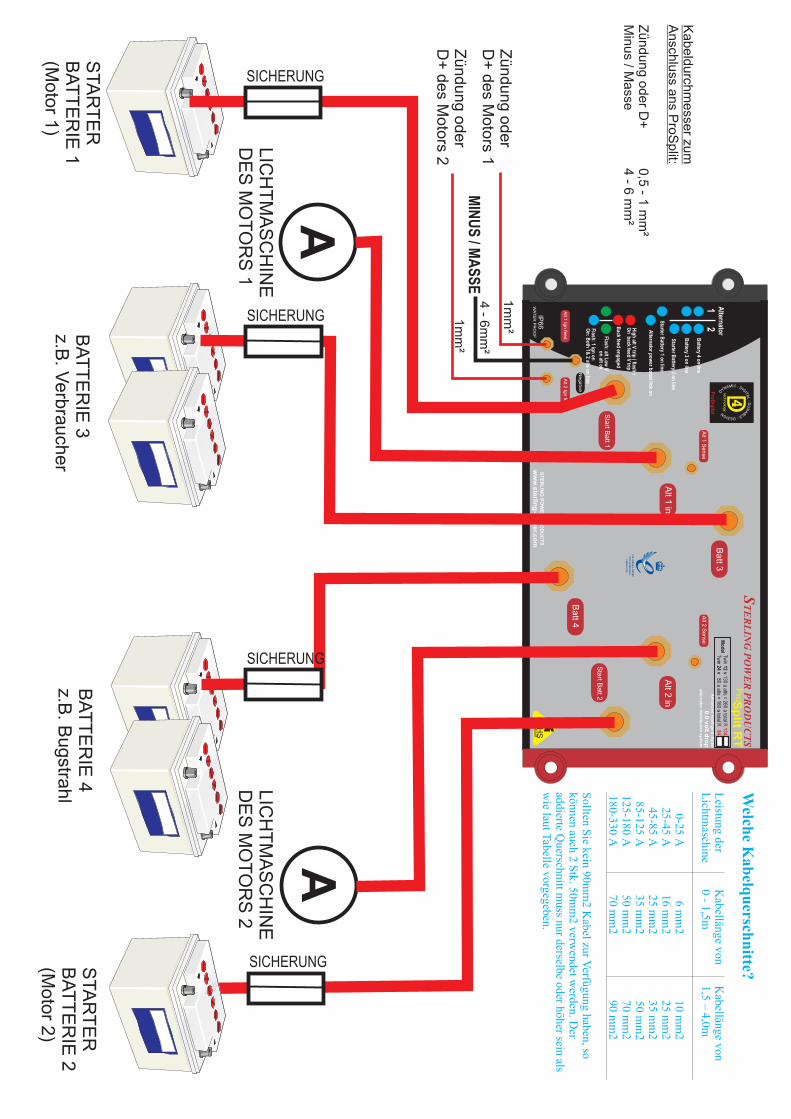
Welche Kabelquerschnitte sie verwenden sollten:
Ein Ladegerät mit Kabellänge von Kabellänge von 0 - 1,5m 1,5 – 4,0m
0-25 A 6 mm2 10 mm2 25-45 A 16 mm2 25 mm2 45-85 A 25 mm2 35 mm2 85-125 A 35 mm2 50 mm2 125-180 A 50 mm2 70 mm2 180-330 A 70 mm2 90 mm2
Sollten Sie kein 90mm2 Kabel zur Verfügung haben, so können auch 2 Stk. 50mm2 verwendet werden. Der addierte Querschnitt muss nur derselbe oder höher sein als wie laut Tabelle vorgegeben.
UL : D RA AITG BI LED : :
DC I
EM SA IN G
NYD
Alt in
Start Batt
Batt 3
Batt 2
Negative
Sence
Motor Starter Batterie Haupt Bordnetzbatteriebank Bugstrahlruder/ Generator/ Zweiter Motor/etc
Motor
Starter Motor
1 oder 2 Lichtmaschinen
Hochleistunglichtmaschinenregleroder Lichtmaschinen-Batterie-Sensor Regler sofern zur Lichtmaschine passend
Sic
heru
ng
Su g
icher n
Si
eru
g
chn
SicherungshalterGANLR
Sicherung 100-500 amps
++
++Zündungs-einspeisung
L htmaschine
icd+ der
o
Zündungseinspeisung
Einzelmotor Doppelmotor (nicht isoliert)
Doppellichtmaschine 3 Batteriebänke
oder
oder plus
UNIVERSAL ADVANCED DIGITAL+ 4 STEP ALTERNATOR REGULATOR
GREEN: HIGH CHARGE RATE ON
YELLOW: TIMER ACTIVATED
RED ONLY : HIGH BATTERY V TRIP FLASHING RED: HIGH BATTERY TEMP
HELP LINE FOR STERLING POWER PRODUCTS TEL U.K 01905 26166
GREEN: FLOAT MODE
ORANGE: LOW VOLTAGE WARNING
BATTERY TYPE: GREEN: GEL/SEALED YELLOW: OPEN LEAD ACID RED: A.G.I.
1 2
ON
1 2
ON
1 2
ONBATTERY TYPE
PROGRAM SELECTORSWITCH, INSIDE LID
3 BATTERY TYPE POSITIONS GEL
SEALEDL.E.D.
( GREEN )
LEADOPENL.E.D.
( YELLOW )
A.G.ML.E.D.( RED )
ALL L.E.D.SFLASHING
HIGH ALTERNATOR
VOLTAGE TRIP
BATTERY NEG TRIP FAULT
GREEN:HIGH ALT TEMP DISENGAGE
YELLOW:12 V SYSTEM SETUP
GREEN: 24 V SYSTEM SETUP
ALTTEMP
BATTERYTEMP
D+SWITCH
EXTRACONNECTIONS
BLOCK
REMOTECONTROLSOCKET
TERLING POWER PRODUCTSS
fan
t
Sic
heun
gr
Lichtmaschi e n
d o er + d
Zündungs inspeisu ge
n
Motor Start Batterie
Hochleistunglicht-maschinenregler
Hochleistunglichtmaschinenregleroder Lichtmaschinen-
Doppelmotor, 4 Batteriebänke
Motor
Starter Motor
Licht maschine
cru
Si
heng
Batt 3
Batt 4Negative
Alternator 1 2
Alt 2 Ign feed
Alt 1 in Alt 2 in
Start Batt 1
Start Batt 2
Alt 1 Sence Alt 2 Sence
+
+
+
+Alt 1 Ign feed
Haupt Bordnetzbatteriebank Bugstrahlruder / Generator
ng
Sicheru
Motor Start Battery
Motor
Starter Motor
Lichtmasch.
UNIVERSAL ADVANCED DIGITAL+ 4 STEP ALTERNATOR REGULATOR
GREEN: HIGH CHARGE RATE ON
YELLOW: TIMER ACTIVATED
RED ONLY : HIGH BATTERY V TRIP FLASHING RED: HIGH BATTERY TEMP
HELP LINE FOR STERLING POWER PRODUCTS TEL U.K 01905 26166
GREEN: FLOAT MODE
ORANGE: LOW VOLTAGE WARNING
BATTERY TYPE: GREEN: GEL/SEALED YELLOW: OPEN LEAD ACID RED: A.G.I.
1 2
ON
1 2
ON
1 2
ONBATTERY TYPE
PROGRAM SELECTORSWITCH, INSIDE LID
3 BATTERY TYPE POSITIONS GEL
SEALEDL.E.D.
( GREEN )
LEADOPENL.E.D.
( YELLOW )
A.G.ML.E.D.( RED )
ALL L.E.D.SFLASHING
HIGH ALTERNATOR
VOLTAGE TRIP
BATTERY NEG TRIP FAULT
GREEN:HIGH ALT TEMP DISENGAGE
YELLOW:12 V SYSTEM SETUP
GREEN: 24 V SYSTEM SETUP
ALTTEMP
BATTERYTEMP
D+SWITCH
EXTRACONNECTIONS
BLOCK
REMOTECONTROLSOCKET
TERLING POWER PRODUCTSS
fan
t
UNIVERSAL ADVANCED DIGITAL+ 4 STEP ALTERNATOR REGULATOR
GREEN: HIGH CHARGE RATE ON
YELLOW: TIMER ACTIVATED
RED ONLY : HIGH BATTERY V TRIP FLASHING RED: HIGH BATTERY TEMP
HELP LINE FOR STERLING POWER PRODUCTS TEL U.K 01905 26166
GREEN: FLOAT MODE
ORANGE: LOW VOLTAGE WARNING
BATTERY TYPE: GREEN: GEL/SEALED YELLOW: OPEN LEAD ACID RED: A.G.I.
1 2
ON
1 2
ON
1 2
ONBATTERY TYPE
PROGRAM SELECTORSWITCH, INSIDE LID
3 BATTERY TYPE POSITIONS GEL
SEALEDL.E.D.
( GREEN )
LEADOPENL.E.D.
( YELLOW )
A.G.ML.E.D.( RED )
ALL L.E.D.SFLASHING
HIGH ALTERNATOR
VOLTAGE TRIP
BATTERY NEG TRIP FAULT
GREEN:HIGH ALT TEMP DISENGAGE
YELLOW:12 V SYSTEM SETUP
GREEN: 24 V SYSTEM SETUP
ALTTEMP
BATTERYTEMP
D+SWITCH
EXTRACONNECTIONS
BLOCK
REMOTECONTROLSOCKET
TERLING POWER PRODUCTSS
fan
tLiMa d+ oder Zundungs-
einspeisungauf LiMa 2
Sicherung
che
ug
Sir
n
c e uSi h r ng
UL : D RA AITG BI LED : :
DC I
EM SA IN G
NYD
Alt in
Start Batt
Batt 3
Batt 2
Negative
Sence+
+Zündungseinspeisung
VerstärkterAusgang
In Verbindung mit einem
Variabel verstärkbare Ausgänge vom
aus nur einem verstärkten Ausgang generieren
Batterie-zu-Batterie Ladegerät
Batterie-zu-Batterie Ladegerät
Motor Starter Batterie Haupt Bordnetzbatteriebank Bugstrahlruder / Gen / Zweitmotor / etc
Motor
Starter Motor
1 oder 2 Lichtmaschinen
hu
Sic
er
ng
ice u
Sh r ngS
iceru
ng
h
+
+
Lichtmaschine d+ oder
Zündungseinspeisung
UL : D RA AITG BI LED : :DC I
EM SA IN G
NYD
Alt in
Start Batt
Batt 3
Batt 2
Negative
Sence
Motor
Starter Motor
1 oder 2 Lichtmasch.
Sic
he
ug
rn
ic
g
She
run
SicherungshalterGANLR
Sicherung100-500 amps
++
++Zündungseinspeisung
a c
Lichtms hine
+r
d ode
nZü dun seinspeisung
g
In Verbindung mit einem
Variabel verstärkbare Ausgänge vom
aus nur einem verstärkten Ausgang generieren
Lichtmaschine-zu-Batterie Ladegerät
Lichtmaschine-zu-Batterie Ladegerät
Boostedoutput
VerstärkterAusgang
Motor BatterieStarter Haupt Bordnetzbatteriebank Bugstrahlruder / Gen / Zweitmotor / etc
Siche ungr
STERLING POWER PRODUCTS
Advanced Intelligent digital
0.0 volt drop alternator distribution system
STERLING POWER PRODUCTS
www.sterling-power.com
technology
4 U: D RLA AT BI
G LI ED :: D
C EI
SM IA GNN
YD
ProDigital
Alt in
Start Batt
Batt 3
12 v systemBattery 3 / on line
Battery 2 / on line
Start Battery/on line
High alt voltage trip ( flashing )High output voltage trip ( solid )
Back feed engaged
Flash alt below 13.3 v/ on alt above 13.3 volts
On ok/Flash stand buy
RoHScompliant
Batt 2
Sence
Pro Split R 180
Negative
Pos Ign feed
7
8
9
10
2
3
4
5
{1
6
11
ProSplit R - Layout & Diagramme
Alle Ausgänge angeschlossen werden. Wenn nicht, dann schließen Sie das unbenutzte Ausgänge auf die Ausgänge verwendet
ST
ER
LIN
G P
OW
ER
PR
OD
UC
TS
ww
w.s
terlin
g-p
ow
er.c
om
tech
no
log
y
4 U
: DR
LA
AT
B
I
G
L
I
E
D
:
:
D
C
E
I
S
M
I
A
GN
NY
D
Pro
Dig
ital
Ba
tt 3
Ba
tt 4N
eg
ativ
e
Altern
ator
1 2
Alt 1
Ign
fee
dA
lt 2 Ig
n fe
ed
Alt 2
Ign
fee
d
Alt 1
in
Sta
rt Ba
tt 1
Alt 1
Se
nse
Alt 2
Se
nse
IP6
6W
AT
ER
PR
OO
F
Hig
h alt V
trip ( flash
)O
n b
ack feed V
trip
Flash
: alt Lo
w V
Back feed
eng
aged
Battery 3 o
n lin
e
Battery 4 o
n lin
e
Starter B
attery 2 on
line
Starter B
attery 1 on
line
Altern
ator p
ow
er bo
ost lin
k on
on
alt ok
Flash
: 1 ign
on
O
n: B
oth
1& 2 alts o
n lin
e
ST
ER
LIN
G P
OW
ER
PR
OD
UC
TS
Twin 12 v 130 a alts = 260 a total
Tw
in 24 v 80 a alts = 160 a total R 134
R 84
Mo
del
Alt 2
in
Sta
rt Ba
tt 2
Ro
HS
com
plia
nt
Ad
van
ce
d In
tellig
en
t dig
ital
0.0
vo
lt dro
p a
ltern
ato
r dis
tribu
tion
syste
m
Sp
lit RT
P
ro
STA
RT
ER
BA
TT
ER
IE 1
(Mo
tor 1
)
LIC
HT
MA
SC
HIN
ED
ES
MO
TO
RS
1L
ICH
TM
AS
CH
INE
DE
S M
OT
OR
S 2
BA
TT
ER
IE 3
z.B. V
erb
rau
che
r
BA
TT
ER
IE 4
z.B. B
ug
strah
l
AA
SICHERUNG
SICHERUNG
Zü
nd
un
g o
de
rD
+ d
es M
oto
rs 1
Zü
nd
un
g o
de
rD
+ d
es M
oto
rs 2
MIN
US
/ MA
SS
E
1m
m²
4 - 6
mm
²
1m
m²
Welch
e Kab
elqu
erschn
itte?
Leistung der
Kabellänge von
Kabellänge von
Lichtm
aschine 0 - 1,5m
1,5 – 4,0m
0-25 A 6 m
m2 10 m
m2
25-45 A 16 m
m2 25 m
m2
45-85 A 25 m
m2 35 m
m2
85-125 A 35 m
m2 50 m
m2
125-180 A 50 m
m2 70 m
m2
180-330 A 70 m
m2 90 m
m2
Sollten S
ie kein 90mm
2 Kabel zur V
erfügung haben, so können auch 2 S
tk. 50mm
2 verwendet w
erden. Der
addierte Querschnitt m
uss nur derselbe oder höher sein als w
ie laut Tabelle vorgegeben.
Ka
be
ldu
rchm
esse
r zum
A
nsch
luss a
ns P
roS
plit:
Zü
nd
un
g o
de
r D+
0,5
- 1 m
m²
Min
us / M
asse
4 - 6
mm
²
STA
RT
ER
BA
TT
ER
IE 2
(Mo
tor 2
)
SICHERUNG
SICHERUNG

Cet appareil nécessite qu’il y ait une masse commune à toutes les batteries et à l’alternateur. Il est conçu pour que l’alternateur et la batterie de démarrage soient reliés quand le moteur est éteint. L’installation est simple, les instructions sont données pour un appareil de 180 ampères, une Ceci est utile pour les alternateurs qui nécessitent d’avoir une tension à leurs bornes pour se mettre entrée et trois sorties et deux entrées et quatre sorties. Cependant un appareil avec deux sorties en route (alternateurs auto excités). se connecte de la même façon avec une sortie en moins.Quand le moteur démarre et que l’alternateur se met en route, le système maintient la connexion Avant de commencer cette installation déconnectez les câbles négatifs et positifs des batteries, avec la batterie de démarrage jusqu’à ce que la tension dépasse 13.3 volts (pour 24volts), ce qui cela évite un court circuit quand on tire les nouveaux câbles, ce qui peut facilement causer un peut prendre quelques minutes ou quelques secondes. L’appareil vérifie ensuite le parc de batteries incendie ou faire exploser la batterie. Travaillez toujours de l’appareil vers le parc de batteries, 2 pour s’assurer que tout est correct et qu’il n’y a pas de court circuit. Puis il enclenche le parc de c'est-à-dire fixez les câbles sur l’appareil, puis le fusible et reliez ensuite à la batterie ce qui est batteries 2 et maintient la batterie de démarrage et le parc 2 connecté à l’alternateur jusqu’à ce que beaucoup plus sur que de commencer par la batterie.les deux atteignent une tension de 13.3 volts (ceci peut prendre quelques minutes de plus en fonction de l’état de charge et la taille du parc de batteries). L’appareil vérifie ensuite le parc de batteries 3 (dans le cas d’un appareil à 3 sorties) et l’enclenche. Ce processus peut prendre seulement 3 secondes dans des conditions normales ou dans des cas extrêmes, avec de grosses batteries déchargées, jusqu’à environ une heure. L’appareil continue à contrôler la tension sur les trois sorties et sur l’entrée de l’alternateur. En théorie ces tensions doivent être égales, si l’une des tensions est inférieure à 13 volts cela signifie qu’un parc de batteries tire trop sur l’alternateur par rapport à sa capacité à fournir le courant au détriment des parcs voisins. Dans cette éventualité l’appareil enverra toute la puissance dans le parc de batteries qui le demande et déconnectera et protégera les autres parcs.
Assurez vous que votre alternateur ou vos alternateurs fonctionnent dans les limites de Noter que l’appareil ne s’éteindra pas dès l’arrêt du moteur. Quand le l’appareil. S’il y a deux alternateurs il faut que la somme des deux intensités n’excède pas
moteur est éteint les parcs de batteries sont isolés, mais les L.E.D fonctionnent encore pendant 10 l’intensité maximum du répartiteur. Pour un répartiteur à deux entrées, chaque sortie peut secondes. prendre en charge la totalité de la puissance (pour un modèle conçu pour deux alternateurs
130A, chaque sortie peut supporter 260A.
1) Dans des conditions de fonctionnement normales, alternateur en route toutes les l.e.d.s doivent être allumées (chacune des leds est allumée dès que la batterie concernée est en charge). Si l’une des l.e.d.s est éteinte regarder dans les instructions ci dessous pour savoir pourquoi le circuit a été déconnecté.2) Si la tension de l’alternateur est supérieure à 16 volts (32V pour les systèmes à 24 volts) l’appareil déconnectera tous les parcs de batteries de l’alternateur ( toutes les l.e.d.s bleues montrant la connexion à chaque parc seront éteintes et cette l.e.d. rouge clignotera), ce qui protégera les batteries d’une surcharge et vous permettra de continuer votre voyage sans vous inquiéter de la détérioration de vos batteries (qui peut aller jusqu’à provoquer une explosion) et de faire réparer le régulateur de l’alternateur à votre prochaine destination. Si au cours du voyage la tension redescendait en dessous de 15 volts, l’appareil Dès que le moteur est démarré l’appareil s’active, au moins une l.e.d. doit s’allumer. L’appareil redémarrerait et recommencerait à charger les parcs de batteries. entre ensuite dans une séquence de test, contrôlant chaque parc de batteries pour s’assurer que
tout fonctionne correctement. Ensuite l’appareil charge la batterie de démarrage jusqu’à ce que sa tension dépasse 13.3 volts, cela peut prendre de 10 secondes à 10 minutes en fonction de l’état de charge de la batterie. Ensuite il connecte le parc de batteries 2 à l’alternateur, jusqu’à ce que sa tension soit de 13.3 volts, ensuite le parc de batteries 3 sera connecté. Toutes les sorties sont maintenant connectées, le système recharge alors tous les parcs de batteries en même temps depuis l’alternateur.Le système continue de contrôler toutes les entrées et toute les sorties. Si on tire du courant sur un parc de batteries, celui qui doit supporter la charge la plus importante (par exemple un guindeau peut être actionné) sera maintenu en ligne avec l’alternateur pour lui fournir le maximum de courant. Les autres parcs de batteries seront isolés pour éviter que celles-ci se déchargent dans la batterie sollicitée.Cet isolement dure jusqu’à ce que le parc de batterie sollicité atteigne une tension de 13,3 volts (ou si la batterie de démarrage a une tension inférieure à 12 ,4 volts). Quand le moteur est éteint l’appareil s’éteint après 10 seconde, il n’utilise pas de puissance.
Ceci est un montage spécifique utile pour les bateaux à moteur disposant de deux moteurs (Yanmar, Volvo…), chacun des moteurs est en général équipé d’un alternateur 110A. Sur une installation classique, une grande partie de l’énergie produite par les alternateurs n’est pas utilisée chacun des alternateurs rechargeant un nombre restreint et défini de parcs de batteries. La mise en place d’un répartiteur pro split R avec deux
Si cette l.e.d est éteinte, la tension de l’alternateur est inférieure à 10 volts (ce qui veut dire que entrées alternateur permet de transmettre l’énergie de façon optimale sur l’ensemble des parcs. l’alternateur ne fonctionne pas). Si cette l.e.d est allumée en continu alors la puissance est supérieure à 13.3 volts et l’alternateur fonctionne normalement.
6) Borne négatif , il s’agit du dispositif de contrôle des bornes négatives un simple câble supportant 10 ampères (2.5mm2) est suffisant pour le faire fonctionner, il doit être connecté aux bornes négatives communes à toutes les batteries et à l’alternateur.7) Sonde de tension des batteries: C’est ici que nous recommandons de placer la sonde de tension provenant d’un régulateur d’alternateur évolué ou d’un alternateur disposant d’une sonde de tension. Cela permet d’assurer que le régulateur charge tous les parcs de batteries de la même façon et empêche toute surcharge. Si aucun de ces deux appareils n’est utilisé avec l’alternateur, ne vous préoccupez pas de cette connexion.8) Borne de connexion des parcs de batteries auxiliaires 2 et 3: (Sur un système à deux sorties il y En cas de décharge de la batterie de démarrage le système fonctionne à l’aide d’un minuteur. aura seulement un parc de batteries auxiliaire). Liaison avec les parcs de batterie autres que la A la première alerte si la batterie de démarrage est trop faible (la tension passe sous 12.6V) batterie de démarrage du moteur à laquelle le moteur est relié. l’appareil maintient uniquement cette batterie connectée à l’alternateur pendant une minute. 9) Entrée de l’alternateur: Il s’agit du câble de puissance de l’alternateur (B+), il pourrait aussi être Ensuite, il se rebranche pour recharger les autres batteries, si de nouveau la batterie de utilisé pour un chargeur de batteries ou pour la sortie d’un alternateur vers un chargeur de batteries démarrage donne des signes de faiblesse, la connexion directe va durer 2 minutes puis les autres etc pour augmenter le nombre de batteries que vous voulez charger. batteries reviennent en ligne et ainsi de suite. Si l’alarme est toujours déclenchée votre 10) Il est recommandé d'utiliser cette borne pour la batterie de démarrage, il n’y a pas de réel alternateur n’est pas assez puissant, il faut envisager d’installer un autre alternateur.problème si on ne l’utilise pas pour la batterie de démarrage. La seule raison est que la batterie connectée à cette borne est utilisée pour fournir une tension à l'alternateur au départ (ceci est nécessaire pour certains types d'alternateur), il est donc important que la batterie connectée à cette borne soit correctement chargée afin d'assurer le fonctionnement de l'alternateur. Le système est aussi étudié pour donner la priorité de recharge à cette batterie.11) Alimentation du boîtier. A Relier directement à la borne D+ de l’alternateur ou à n’importe quelle alimentation qui fonctionne quand le moteur est en route et qui s’éteint quand le moteur s’arrête. Cela informe l’appareil que le moteur est en marche et l’alimente.
Installation:
Fusibles:
Il continuera cependant à contrôler la batterie de démarrage en tant que parc le plus important, et si à tout moment la tension de la batterie de démarrage descend en dessous de 12.6 volts, alors tous les parcs de batteries seront déconnectés et toute la puissance sera dirigée vers la batterie de démarrage jusqu’à ce que la tension remonte à 13.3 volts. Puis la procédure de démarrage recommencera. Il s’agit d’un cas peu probable mais c’est un système de sécurité inclus dans le logiciel pour donner la priorité au démarrage du moteur.
Connecter la batterie de démarrage à la borne marquée Start bat
Connexion négative:
Tension Alternateur élevée (l.e.d.rouge clignotante):Alimentation d’excitation:
Comment l’appareil fonctionne t-il et que peut on en attendre ?
2) Problème d’un excès de tension sur un des parcs (l.e.d.rouge clignotante allumée en continue):
3) Retour du courant (l.e .d. rouge allumée):
Autres utilisations:
Fonctionnement et alarmes:
Rappelez vous que la meilleure façon d’optimiser le rendement de l’alternateur est de mettre en place un chargeur d’alternateur ou un régulateur d’alternateur Sterling.
Autres utilisations de ce produit: Peut être utilisé avec un chargeur de batteries à sortie unique pour le transformer en chargeur à sorties multiples, avec une éolienne, avec des panneaux solaires.Pour tirer le meilleur parti de votre alternateur, il est recommandé d’utiliser ce produit en complément du chargeur d’alternateur ou du régulateur d’alternateur Sterling.
Extinction de l’appareil:
Régulateurs d’alternateurs ou alternateurs disposant d’une sonde de tension batteries:
Informations sur les L.E.D situées sur le devant de l’appareil:Batterie de démarrage/ batterie 2 , batterie 3, démarreur 2, sous tension (l.e.d.s bleues):
Installation double Alternateur:
Double moteur, double alternateur:
5) l.e.d bleue:
Il est recommandé de placer les fusibles le plus près possible de la batterie et de les installer le plus tôt possible, afin qu’ils protègent des incidents pouvant survenir pendant l’installation. Les fusibles protègent au cas où un câble entre en contact avec le châssis d’un véhicule ou une coque en acier d’un bateau. Les fusibles ne sont pas fournis avec l’appareil, ils peuvent être achetés chez Seatronic. Pour les fusibles conduisant une forte intensité, nous recommandons de choisir des fusibles 50 pour cent plus grands que l’intensité maximum possible en arrondissant au 50 ampères le plus proche.Il est recommandé de lire toutes les fonctions d’alarme, cela peut vous aider à mieux comprendre le système.Pour installer l’appareil choisir un endroit frais dans le compartiment moteur, c'est-à-dire aussi bas que possible. Le sens dans lequel on installe l’appareil n’a pas d’importance, mais il a été conçu pour que les câbles ne passent pas par-dessus les bornes qui proviennent d’autres parcs de batteries. Vous pouvez connecter l’appareil sous n’importe quel angle afin de faciliter le câblage. Utiliser les quatre trous de fixation pour fixer fermement l’appareil sur une cloison. Quand tous les câbles sont connectés, lier et sécuriser les câbles de façon à ce qu’ils ne vibrent pas et qu’ils ne touchent aucun autre plot.
Une connexion spécifique est disponible sur l’appareil pour les régulateurs évolués et les alternateurs Fixer l’appareil dans une position pour raccourcir la longueur des câbles utilisés plus les câbles possédant des sondes de tension batteries (Volvo). Il est fortement recommandé d’utiliser ce sont courts mieux c’est. Reporter vous aux tableaux adjoints pour déterminer le diamètre des dispositif pour obtenir les meilleures performances de l’alternateur et compenser une chute de câbles.tension entre l’alternateur et la boite de contrôle. . Cette connexion est
recommandée pour la batterie de démarrage mais elle peut aussi être utilisée pour une autre batterie, l’intérêt de cette liaison a été expliqué au point 10 précédent.
Cette connexion est destinée à l’alimentation de l’électronique interne, le courant dans ce câble ne dépasse pas 2 ampères, ainsi un câble 5-10 amp (2.5mm2) suffit largement pour cette connexion. Cette borne peut être reliée à la borne négative du parc de batteries principal ou à n’importe quelle borne négative de l’installation.
Il s’agit d’une alimentation. Par exemple on peut utiliser la d+/61/L/ derrière l’alternateur, ou une alimentation directe sur la clé de contact, ou toute autre borne qui est alimentée quand le moteur fonctionne. Il s’agit d’informer l’appareil que le moteur fonctionne (la tension de ce câble doit alors être à 12V).
Il s’agit du cas où une tension de 16 volts est détectée aux bornes d’un des parcs de batteries, il peut par exemple être causé par un chargeur de batterie défectueux sur le parc de batteries 3 essayant de renvoyer cette tension vers d’autres parcs de batteries. L’appareil identifiera le parc de batterie en cause et l’isolera pour éviter que le reste du système soit détérioré. Cependant l’appareil n’est pas en mesure de limiter la détérioration éventuelle du parc de batteries en cause, pour cela consulter notre nouvelle gamme de relais sensibles, limitateurs de tension.
Situation où l’un des parcs de batteries essaie de décharger les autres. Par exemple si un convertisseur de grande puissance (3000 watts) était branché sur un parc de batteries de servitude, celui ci étant peu chargé, si quelqu’un branchait un appareil, le convertisseur essaierait de tirer 200 ampères sur les autres parcs. Cette situation serait détectée par l’appareil, qui déconnecterait les autres parcs de batteries et l’alternateur serait alors branché sur le parc du convertisseur uniquement, jusqu’à ce que la forte demande soit arrêtée et que ce parc de batteries revienne à 13.3 volts. Les autres parcs de batteries se remettraient en ligne comme il est expliqué dans la séquence de démarrage. Si la limite de sécurité de tension sur la Deux alternateurs ou même plus peuvent être installés sur batterie du moteur était atteinte cela déconnecterait toutes les batteries et dirigerait la puissance sur l’entrée alternateur. Ils peuvent être sur le même moteur ou sur des moteurs différentsla batterie de démarrage.
Si cette l.e.d. clignote, alors la tension de l’alternateur est inférieure à 13.3 volts (26.6 volts pour 24 volts). Ceci peut se produire si le câble reliant l’alternateur et l’appareil est trop fin ou trop long pour la quantité de courant ou si il y a une forte demande sur un parc de batteries.
Cet appareil peut être utilisé pour d’autres fonctions, sachant qu’il n’y a aucune perte de tension quand le courant le traverse, il peut diviser les sorties depuis n’importe quelle source d’électricité et distribuer le courant à différents parcs de batteries. On peut l’utiliser avec un chargeur de batteries qui n’a qu’une entrée pour recharger plusieurs parcs.,. il suffit de connecter la sortie puissance de l’appareil à la borne consacrée à l’alternateur.
En fonctionnement normal, les alarmes ne doivent pas être activées, certaines alarmes ont un fonctionnement déterministe (ex alarme de sécurité qui débranche l’alternateur lorsque celui-ci a une tension trop élevée), d’autres ont un fonctionnement moins systématique, c’est par exemple le cas de celle qui assure la priorité de recharge à la batterie de démarrage comme le démontre l’exemple ci dessous.
4) Etat de puissance de l’alternateur:
Si cette l.e.d est allumée l’appareil fonctionne normalement. Si cette l.e.d clignote cela signifie que l’alternateur est éteint ou ne fonctionne pas. L’appareil est en mode veille.
ProSplit R - Fonctions + Installation
UL : D RA AITG BI LED : :
DC I
EM SA IN G
NYD
Alt in
Start Batt
Batt 3
Batt 2
Negative
Sence
Batterie de démarrage Parc de service principal Parc de service secondaire
moteur
1 ou 2 alternateurs
Régulateur d’alternateuravancé ou alternateur disposant d’une sonde de batterie intégreé au régulateur
fusi
ble
f s bu i le
fusi
ble
Porte fusibleGANLR
fusible100-500 amps
++
++ignition feed
d+ alternateur(excitation)
Moteur uniquedeux moteurs ( non isolés )
deux alternateurs3 parcs batterie
ou ou avec
UNIVERSAL ADVANCED DIGITAL+ 4 STEP ALTERNATOR REGULATOR
GREEN: HIGH CHARGE RATE ON
YELLOW: TIMER ACTIVATED
RED ONLY : HIGH BATTERY V TRIP FLASHING RED: HIGH BATTERY TEMP
HELP LINE FOR STERLING POWER PRODUCTS TEL U.K 01905 26166
GREEN: FLOAT MODE
ORANGE: LOW VOLTAGE WARNING
BATTERY TYPE: GREEN: GEL/SEALED YELLOW: OPEN LEAD ACID RED: A.G.I.
1 2
ON
1 2
ON
1 2
ONBATTERY TYPE
PROGRAM SELECTORSWITCH, INSIDE LID
3 BATTERY TYPE POSITIONS GEL
SEALEDL.E.D.
( GREEN )
LEADOPENL.E.D.
( YELLOW )
A.G.ML.E.D.( RED )
ALL L.E.D.SFLASHING
HIGH ALTERNATOR
VOLTAGE TRIP
BATTERY NEG TRIP FAULT
GREEN:HIGH ALT TEMP DISENGAGE
YELLOW:12 V SYSTEM SETUP
GREEN: 24 V SYSTEM SETUP
ALTTEMP
BATTERYTEMP
D+SWITCH
EXTRACONNECTIONS
BLOCK
REMOTECONTROLSOCKET
TERLING POWER PRODUCTSS
fan
t
UNIVERSAL ADVANCED DIGITAL+ 4 STEP ALTERNATOR REGULATOR
GREEN: HIGH CHARGE RATE ON
YELLOW: TIMER ACTIVATED
RED ONLY : HIGH BATTERY V TRIP FLASHING RED: HIGH BATTERY TEMP
HELP LINE FOR STERLING POWER PRODUCTS TEL U.K 01905 26166
GREEN: FLOAT MODE
ORANGE: LOW VOLTAGE WARNING
BATTERY TYPE: GREEN: GEL/SEALED YELLOW: OPEN LEAD ACID RED: A.G.I.
1 2
ON
1 2
ON
1 2
ONBATTERY TYPE
PROGRAM SELECTORSWITCH, INSIDE LID
3 BATTERY TYPE POSITIONS GEL
SEALEDL.E.D.
( GREEN )
LEADOPENL.E.D.
( YELLOW )
A.G.ML.E.D.( RED )
ALL L.E.D.SFLASHING
HIGH ALTERNATOR
VOLTAGE TRIP
BATTERY NEG TRIP FAULT
GREEN:HIGH ALT TEMP DISENGAGE
YELLOW:12 V SYSTEM SETUP
GREEN: 24 V SYSTEM SETUP
ALTTEMP
BATTERYTEMP
D+SWITCH
EXTRACONNECTIONS
BLOCK
REMOTECONTROLSOCKET
TERLING POWER PRODUCTSS
fan
t
STERLING POWER PRODUCTS
Advanced Intelligent digital
0.0 volt drop alternator distribution system
STERLING POWER PRODUCTS
www.sterling-power.com
technology
4 U: D RLA AT BI
G LI ED :: D
C EI
SM IA GNN
Y D
ProDigital
Alt in
Start Batt
Batt 3
12 v systemBattery 3 / on line
Battery 2 / on line
Start Battery/on line
High alt voltage trip ( flashing )High output voltage trip ( solid )
Back feed engaged
Flash alt below 13.3 v/ on alt above 13.3 volts
On ok/Flash stand buy
RoHScompliant
Batt 2
Sence
Pro Split R 180
Negative
Pos Ign feed
7
8
9
10
2
3
4
5
{1
6
11
UL : D RA AITG BI LED : :
DC I
EM SA IN G
NYD
Alt in
Start Batt
Batt 3
Batt 2
Negative
Sence
Batterie de démarrage Parc de service principal Parc de batterie secondaire
moteurdémarreur
1 ou 2 alternateurs
us
bl
fi
e
fusible
ufsi
ble
Porte fusibleGANLR
fusible100-500 amps
++
++ignition feed
alternatord+ or
ignition feed
Utilisé en combinaison avec un
ceci permet d’augmenter le nombre desorties amplifiées du
chargeur d’alternateur
chargeur d’alternateur
BoostedoutputSortie
Boostée
Utilisé en combinaison avec un
ceci permet de booster plusieurs batteries une seul parc de batteries
chargeur de batterie à batterie (position A) ou
(position B)
Batterie de démarrage Parc de service principal Parc de service secondaire
moteur
démarreur
1 or 2 alternateurs
sl
fuib
e
fusib el
usi
bf
le
alternateurd+ ou
excitation
Batt 3
Batt 4Negative
Alternator 1 2
Alt 2 Ign feed
Alt 1 in Alt 2 in
Start Batt 1
Start Batt 2
Alt 1 Sence Alt 2 Sence
+
+
+
+Alt 1 Ign feed
Parc de service principal Parc de batterie secondaire
fusibleible
fus
Batterie de démarrage
Batterie démarrage
moteurdémarreur
alternateur
moteur
démarreur
alternateur
Deux moteurs, 4 batteries
UNIVERSAL ADVANCED DIGITAL+ 4 STEP ALTERNATOR REGULATOR
GREEN: HIGH CHARGE RATE ON
YELLOW: TIMER ACTIVATED
RED ONLY : HIGH BATTERY V TRIP FLASHING RED: HIGH BATTERY TEMP
HELP LINE FOR STERLING POWER PRODUCTS TEL U.K 01905 26166
GREEN: FLOAT MODE
ORANGE: LOW VOLTAGE WARNING
BATTERY TYPE: GREEN: GEL/SEALED YELLOW: OPEN LEAD ACID RED: A.G.I.
1 2
ON
1 2
ON
1 2
ONBATTERY TYPE
PROGRAM SELECTORSWITCH, INSIDE LID
3 BATTERY TYPE POSITIONS GEL
SEALEDL.E.D.
( GREEN )
LEADOPENL.E.D.
( YELLOW )
A.G.ML.E.D.( RED )
ALL L.E.D.SFLASHING
HIGH ALTERNATOR
VOLTAGE TRIP
BATTERY NEG TRIP FAULT
GREEN:HIGH ALT TEMP DISENGAGE
YELLOW:12 V SYSTEM SETUP
GREEN: 24 V SYSTEM SETUP
ALTTEMP
BATTERYTEMP
D+SWITCH
EXTRACONNECTIONS
BLOCK
REMOTECONTROLSOCKET
TERLING POWER PRODUCTSS
fan
t
d+ alternateur(excitation)
d+ alternateur(excitation) fu
ble
si
f seu
fuse
fuse
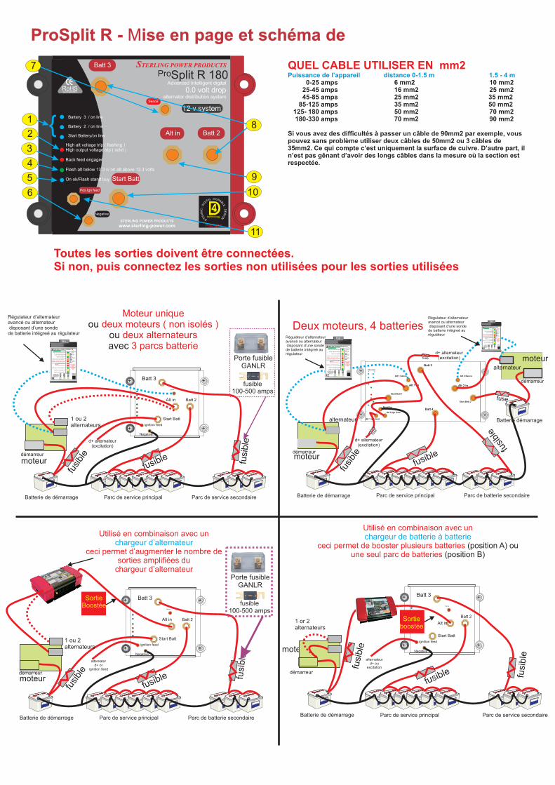
QUEL CABLE UTILISER EN mm2Puissance de l’appareil distance 0-1.5 m 1.5 - 4 m 0-25 amps 6 10 25-45 amps 16 mm2 25 mm2 45-85 amps 25 mm2 35 mm2 85-125 amps 35 mm2 50 mm2 125- 180 amps 50 mm2 70 mm2 180-330 amps 70 mm2 90 mm2
Si vous avez des difficultés à passer un câble de 90mm2 par exemple, vous pouvez sans problème utiliser deux câbles de 50mm2 ou 3 câbles de 35mm2. Ce qui compte c’est uniquement la surface de cuivre. D’autre part, il n’est pas gênant d’avoir des longs câbles dans la mesure où la section est respectée.
mm2 mm2
Régulateur d’alternateuravancé ou alternateur disposant d’une sonde de batterie intégreé au régulateur
Régulateur d’alternateuravancé ou alternateur disposant d’une sonde de batterie intégreé au régulateur
démarreur
UL : D RA AITG BI LED : :
DC I
EM SA IN G
NYD
Alt in
Start Batt
Batt 3
Batt 2
Negative
Sence
+
+ignition feed
+
+
Sortieboostée
Toutes les sorties doivent être connectées. Si non, puis connectez les sorties non utilisées pour les sorties utilisées
ProSplit R - Mise en page et schéma de