Embed Size (px)
Citation preview
www.ledvance.com/substitube
Installation Instructions
SubstiTUBE®
T8
T5

www.ledvance.com/substitube
Portfolio
Product lineSubstiTUBE®
EM
SubstiTUBE®
Universal
SubstiTUBE®
HF
T8
Compatibility
Electromagnetic
driver (EM/CCG)
and line voltage
(220-240V)
Electromagnetic driver
(EM/CCG)
High frequency /
electronic driver
(HF/ECG) and line voltage
(220-240V)
High frequency /
electronic driver
(HF/ECG).
Operation with
ECG in luminaire
only!
Product lineSubstiTUBE®
HF
SubstiTUBE®
AC
T5
Compatibility
High frequency / electronic driver (HF/ECG).
Operation with ECG in luminaire only!
Line voltage
(220-240V)

Installation Instructions SubstiTUBE® | S EU-W LL PM TUB
August.2018
3
Agenda
1. Installation options
1.1 Test
2. SubstiTUBE® T8 EM
2.1 Retrofitting in a CCG luminaire
2.1.1 Luminaires with compensating capacitor
2.1.2 Duo circuit lamp luminaire
2.1.3 Tandem operation
2.2 Conversion / Direct Wiring
2.2.1 Direct line voltage connection
2.2.2 Sample installation direct wiring
3. SubstiTUBE® T8 and T5 HF
3.1 Retrofitting in a ECG luminaire
3.2 Multi circuit lamp luminaire
4. SubstiTUBE® T8 Universal
4.1 Retrofitting in a CCG luminaire
4.1.1 Luminaires with compensating capacitor
4.2 Retrofitting in a ECG luminaire
4.3 Conversion / Direct Wiring
5. SubstiTUBE® T5 AC
5.1 Conversion / Direct Wiring
5.1.1 Direct line voltage connection
5.1.2 Sample installation direct wiring

Installation Instructions SubstiTUBE® | S EU-W LL PM TUB
August.2018
4
1. Installation options
I) Retrofitting a CCG luminaire accord. to EN 62776
Replacing fluorescent T8-tube and installed starter by SubstiTUBE® EM T8 and
SubstiTUBE® Start.
II) Conversion of an ECG or CCG luminaire
Rewiring of the luminaire necessary for replacing fluorescent tube by
SubstiTUBE® EM in ECG luminaires. Rewiring is also possible for replacement
by SubstiTUBE® EM in CCG luminaires. Installation must be done by qualified
Electricians and all security precautions described herein must be followed.
Please refer to chapter 2.2.2 “Sample installation direct wiring” for more details.
III) Retrofitting an ECG luminaire accord. to EN 62776
Replacing conventional fluorescent T8 tube by SubstiTUBE® HF T8. Before
retrofitting, check driver compatibility list on www.ledvance.com/ecg-compatibility,
as SubstiTUBE® HF has to be compatible with installed ECG.
SubstiTUBE®
EM
CCG luminaire
ECG luminaire
Retrofitting a CCG
luminaire
Direct wiring
Overview of possible installations
SubstiTUBE®
HFECG luminaire
Retrofitting an
ECG luminaire

Installation Instructions SubstiTUBE® | S EU-W LL PM TUB
August.2018
5
1. Installation options1.1 Test
Starter test Camera test
Check whether the luminaire in which
the new lamp should be used has a
starter. If it has, you need a
SubstiTUBE for operation on a CCG.
If it doesn’t have a starter, use the
ECG-compatible variant.
A functional T8 fluorescent lamp is still
installed in the luminaire. Observe this
through a digital camera (e.g. on your
smartphone or tablet). If the light
flickers, you need a SubstiTUBE for
operation on a CCG. Otherwise, use
the ECG-compatible variant.
You are not sure whether you require a lamp for operation on a CCG or ECG?
Two simple test are available to quickly find the suitable product.
Installation Instructions SubstiTUBE® | S EU-W LL PM TUB
August.2018
6
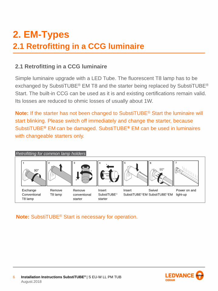
2. EM-Types2.1 Retrofitting in a CCG luminaire
Simple luminaire upgrade with a LED Tube. The fluorescent T8 lamp has to be
exchanged by SubstiTUBE® EM T8 and the starter being replaced by SubstiTUBE®
Start. The built-in CCG can be used as it is and existing certifications remain valid.
Its losses are reduced to ohmic losses of usually about 1W.
Note: If the starter has not been changed to SubstiTUBE® Start the luminaire will
start blinking. Please switch off immediately and change the starter, because
SubstiTUBE® EM can be damaged. SubstiTUBE® EM can be used in luminaires
with changeable starters only.
2.1 Retrofitting in a CCG luminaire
Note: SubstiTUBE® Start is necessary for operation.
Retrofitting for common lamp holders
Exchange
Conventional
T8 lamp
Remove
T8 lamp
Remove
conventional
starter
Insert
SubstiTUBE®
starter
Insert
SubstiTUBE®EM
Swivel
SubstiTUBE®EM
Power on and
light-up
Installation Instructions SubstiTUBE® | S EU-W LL PM TUB
August.2018
7
2. EM-Types2.1 Retrofitting in a CCG luminaire
Circuit diagram of a retrofitted double lamp CCG luminaire
SubstiTUBE®
SubstiTUBE® Start
CCG
UN
SubstiTUBE®
SubstiTUBE® Start
CCGp.f. corretion capacitor
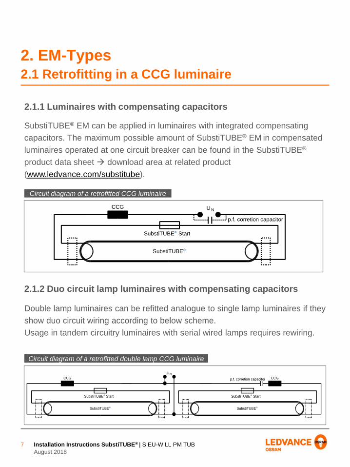
Double lamp luminaires can be refitted analogue to single lamp luminaires if they
show duo circuit wiring according to below scheme.
Usage in tandem circuitry luminaires with serial wired lamps requires rewiring.
2.1.2 Duo circuit lamp luminaires with compensating capacitors
Circuit diagram of a retrofitted CCG luminaire
SubstiTUBE®
SubstiTUBE® Start
CCG UN
p.f. corretion capacitor
2.1.1 Luminaires with compensating capacitors
SubstiTUBE® EM can be applied in luminaires with integrated compensating
capacitors. The maximum possible amount of SubstiTUBE® EM in compensated
luminaires operated at one circuit breaker can be found in the SubstiTUBE®
product data sheet download area at related product
(www.ledvance.com/substitube).

Installation Instructions SubstiTUBE® | S EU-W LL PM TUB
August.2018
8
2. EM-Types2.1 Retrofitting in a CCG luminaire
2.1.3 Tandem operation
SubstiTUBE® Advanced EM tubes (0,6M) are suitable for tandem operation, a
circuit diagram is shown below.
Circuit diagram of a lamp in tandem operation
SubstiTUBE ® SubstiTUBE ®
SubstiTUBE Start SubstiTUBE Start

Installation Instructions SubstiTUBE® | S EU-W LL PM TUB
August.2018
9
2. EM-Types2.2 Conversion / Direct Wiring
2.2.1 Direct line voltage connection
SubstiTUBE® EM products can be operated at direct mains voltage 220V-240V.
To eliminate remaining losses in CCG luminaires it is also possible to convert
those fittings for direct mains operation with SubstiTUBE® EM. Conversion must
be done according to below description in 2.2.2 “Sample installation direct wiring”.
Rewire a luminaire on both sides as shown below. Thus SubstiTUBE® EM can be
inserted in any direction with standardized IEC compliant G13 lamp holders. All
wires need to be approved for the existing voltages and appliance class. Usually
solid wires with single isolation can be used for class I, double insulation wires
could be used for class II. The maximum wire cross-section for lamp holders and
starters is typically 0.5mm2. Built-in control gears must not remain connected after
rewiring.
Direct wiring circuit diagram of a retrofitted luminaire
SubstiTUBE®
SubstiTUBE® StartUN

Installation Instructions SubstiTUBE® | S EU-W LL PM TUB
August.2018
10
2. EM-Types2.2 Conversion / Direct Wiring
Note: Rewiring by qualified electricians only.
Make sure that the supply voltage is disconnected
Remove the conventional lamp
Remove power factor correction capacitor (if installed) to improve power
factor
Rewire the luminaire as shown in the circuit diagram on the page before
Note: Use of SubstiTUBE® Start or a fuse (250V, T2A) is recommended.
Insert SubstiTUBE® EM into lamp holders
Make sure with appropriate tests, that the rewired luminaire complies to all
relevant safety requirements and other applicable regulations, e.g. acc. to
DIN VDE 0701-0702 or 2004/108/EC
Mark rewired luminaire with new nameplate
Installation instruction:
SubstiTUBE®
UN
SubstiTUBE®
SubstiTUBE® Start or fuse
Direct wiring circuit diagram of a retrofitted double lamp luminaire
Installation Instructions SubstiTUBE® | S EU-W LL PM TUB
August.2018
11
2. EM-Types2.2 Conversion / Direct Wiring
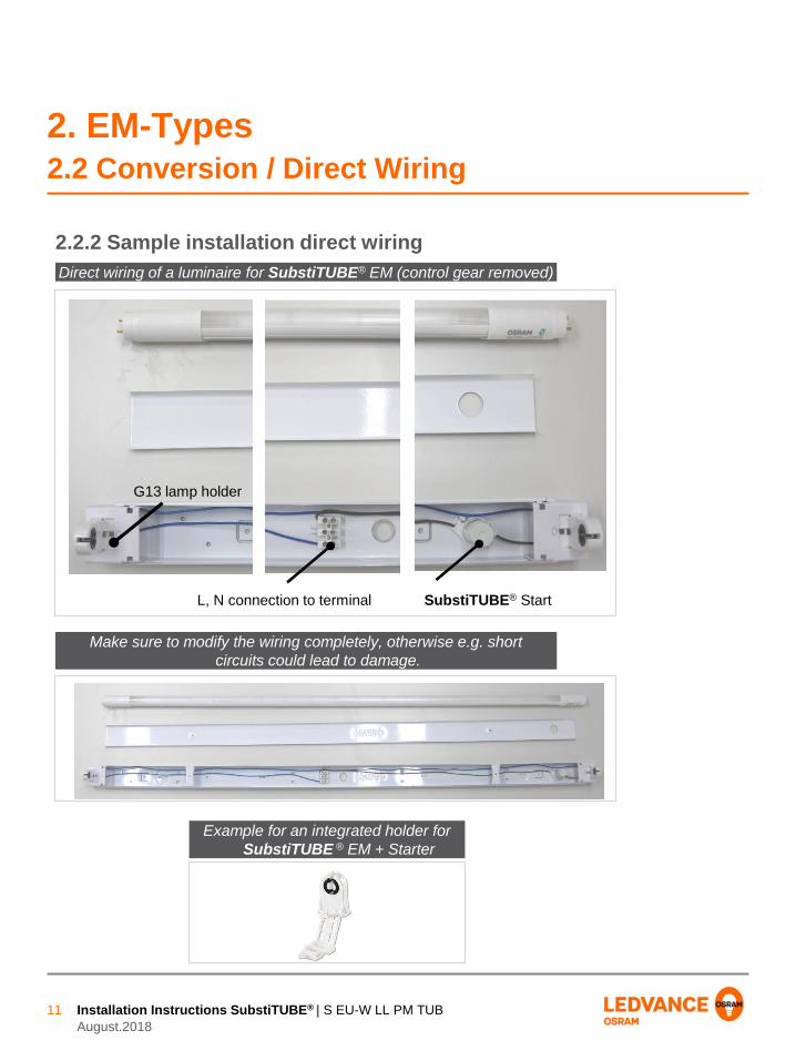
2.2.2 Sample installation direct wiring
L, N connection to terminal SubstiTUBE® Start
G13 lamp holder
Make sure to modify the wiring completely, otherwise e.g. short
circuits could lead to damage.
Example for an integrated holder for
SubstiTUBE ® EM + Starter
Direct wiring of a luminaire for SubstiTUBE® EM (control gear removed)

Installation Instructions SubstiTUBE® | S EU-W LL PM TUB
August.2018
12
3. HF-Types T8 and T5 3.1 Retrofitting in an ECG luminaire
Replacing the lamp is all what needs to be done to upgrade an existing luminaire
with electrical control gear to newest OSRAM® HF-LED-technology. Since only
the lamp is replaced, there is no constructive modification necessary to the
luminaire. The SubstiTUBE® HF tube is compatible with ECGs of various brand
manufacturers. For further information regarding the tested ECGs a compatibility
list is available on www.ledvance.com/ecg-compatibility .
Energy consumption on ballast level will not be reduced by retrofitting, compared
to a retrofitted CCG luminaire.
This is part of the new international safety norm IEC 62776
3.1 Retrofitting in an ECG luminaire
Circuit diagram of a retrofitted ECG luminaire
SubstiTUBE® HF
UN
EVG

Installation Instructions SubstiTUBE® | S EU-W LL PM TUB
August.2018
13
3. HF-Types T8 and T5 3.1 Retrofitting in an ECG luminaire
Please check ballast compatibility prior to installation
www.ledvance.com/ecg-compatibility
Retrofitting for common lamp holders

Installation Instructions SubstiTUBE® | S EU-W LL PM TUB
August.2018
14
3. HF-Types T8 and T5 3.2 Multi circuit lamp luminaire
Double lamp luminaires can be retrofitted analogue to single lamp luminaires.
Only the fluorescent lamps have to be replaced by SubstiTUBE® HF tubes.
An example wiring for luminaires with OSRAM® ECGs is shown below.
3.2 Multi circuit lamp luminaires
ECG luminaires with more than two lamps are wired similarly.
However, the wiring of the luminaire remains the same after retrofitting with
SubstiTUBE® HF.
Circuit diagram of a retrofitted double lamp ECG luminaire
SubstiTUBE® HF
UN EVG
SubstiTUBE®HF

Installation Instructions SubstiTUBE® | S EU-W LL PM TUB
August.2018
15
4.2 Retrofitting in a CCG luminaire
Please follow instructions on pages 12 - 13
4.3 Conversion / Direct Wiring
Please follow instructions on pages 9 - 11
4.3 Conversion / Direct Wiring
4.2 Retrofitting in a CCG luminaire
Please follow instructions on page 7 (2.1.2)
4.1.1 Luminaires with compensating capacitor
4.1 Retrofitting in a CCG luminaire
4. Universal-Types4.1 Retrofitting in a CCG luminaire
Please follow instructions on page 6
Installation Instructions SubstiTUBE® | S EU-W LL PM TUB
August.2018
16
5. AC-Types T55.1 Conversion / Direct Wiring
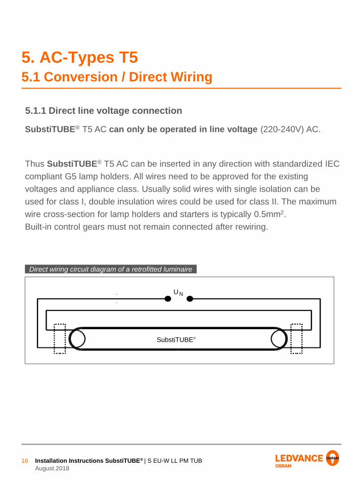
5.1.1 Direct line voltage connection
SubstiTUBE® T5 AC can only be operated in line voltage (220-240V) AC.
Thus SubstiTUBE® T5 AC can be inserted in any direction with standardized IEC
compliant G5 lamp holders. All wires need to be approved for the existing
voltages and appliance class. Usually solid wires with single isolation can be
used for class I, double insulation wires could be used for class II. The maximum
wire cross-section for lamp holders and starters is typically 0.5mm2.
Built-in control gears must not remain connected after rewiring.
Direct wiring circuit diagram of a retrofitted luminaire
SubstiTUBE®
UN
Installation Instructions SubstiTUBE® | S EU-W LL PM TUB
August.2018
17
5. AC-Types T55.1 Conversion / Direct Wiring
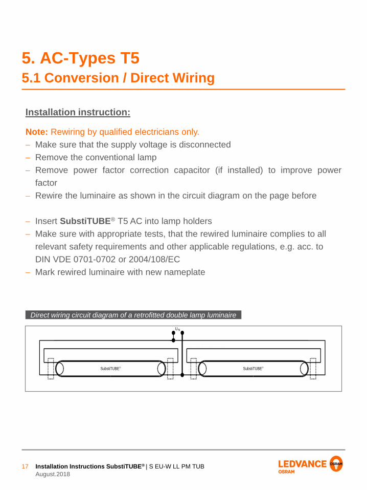
Note: Rewiring by qualified electricians only.
Make sure that the supply voltage is disconnected
Remove the conventional lamp
Remove power factor correction capacitor (if installed) to improve power
factor
Rewire the luminaire as shown in the circuit diagram on the page before
Insert SubstiTUBE® T5 AC into lamp holders
Make sure with appropriate tests, that the rewired luminaire complies to all
relevant safety requirements and other applicable regulations, e.g. acc. to
DIN VDE 0701-0702 or 2004/108/EC
Mark rewired luminaire with new nameplate
Installation instruction:
SubstiTUBE®
UN
SubstiTUBE®
SubstiTUBE® Start or fuse
Direct wiring circuit diagram of a retrofitted double lamp luminaire

www.ledvance.com/substitube
Disclaimer
All information contained in this document has been
collected, analyzed and verified with great care by
LEDVANCE. However, LEDVANCE is not responsible for the
correctness and completeness of the information contained
in this document and LEDVANCE cannot be made liable for
any damage that occurs in connection with the use of and/or
reliance on the content of this document. The information
contained in this document reflects the current state of
knowledge on the date of issue.
LEDVANCE GmbH
Parkring 29-33
85748 Garching/Munich
Germany
Telefon +49 89 6780673 100
Fax +49 89 6780673 101
Email [email protected]
www.ledvance.com