Embed Size (px)
Citation preview
INN
Mechanical EngiReering
UNivf'.Rsrry01'-
lT,L.I,ll!liMty


Digitized by the Internet Archive
in 2013
http://archive.org/details/powerplantdesignOOIinn

POWER PLANT DESIGN FOR GAS POWER
HOMER ROBERTS LINN
B. S. University of Illinois, 1896
THESIS
Submitted in Partial Fulfillment of the Requirements for
Degree of
MECHANICAL ENGINEER
IN
THE GRADUATE SCHOOL
OF THE
UNIVERSITY OF ILLINOIS
1909

\t)Ot)

an
UNIVERSITY OF ILLINOIS
THE GRADUATE SCHOOL
May 1.., 190 9
I HEREBY RECOMMEND THAT THE THESIS PREPARED UNDER MY SUPERVISION BY
HOMER HCBERTS him, B . S . , 1896
ENTITLED PQWEE PLAFT DESIQK FOR GAS POWER
BE ACCEPTED AS FULFILLING THIS PART OF THE REQUIREMENTS FOR THE
nPHRFF OF MECHAKICAL ENGINEER
In Charge of Major Work
Head of Department
Recommendation concurred in:
Committee
on
Final Examination
II


POWER PLANT DESIGN FOR GAS POWER
BY
HOMER ROBERTS LINN, B.S. *96.
THESIS
FOR THE DEGREE OP MECHANICAL ENGINEER
IN THE
GRADUATE SCHOOL
OF THE
UNIVERSITY OF ILLINOIS.
PRESENTED MARCH 27, 1909.

1

SUMMARY
.
Page
History of Internal Combustion Engine 1
Fimdaniental Theory 1
Gas Engine Fuels 3
Comparative Cost of Power with Different Gas Engine Fuels- 7
Some points for Efficient Operation 8
History of Gas Producers 13
Discussion of Principles 16
Essential Points to Consider 18
Blast Furnace Gas Engine Plant at Gary, Ind. 21
Specifications for Suction Gas Producer Plant 25
Suction Gas Producer (Specification) 27
Gas Engine (Specification) 30
(Piping 35( Covering 36
Miscellaneous Specifications (Coal Conveying 36(Foundations- 38(Painting 38
General Plan 40
Elevation of Generator, Economizer and Scrubber 41
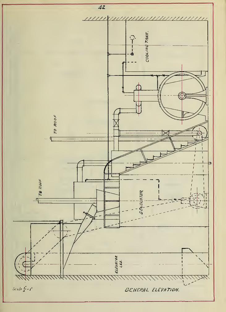
General Elevation 42
Foundation Plan 43


-1-
HISTORY.
In preparing a thesis on an internal combustion engine !
pov/er plant It is interesting as well as profitable to briefl3^
review the history of the development of the gas engine* The
first attempt at producing an Internal combustion engine was In
the 18th century, by an inventor who utilized the explosive effect
of gun-powder, but no further steps were taKen until about 1826,
when Browne brought out his gas vacuum engine in England.
About 1880 the French engineer Lenoir produced an
engine in France, and in 1862 Hugon, another French engineer,
produced an engine which met with no better success than that of
Lenoir. These were low compression engines, and of very low
efficiency.
In 1862 Beau de Rochas, another French engineer, developed
an engine v/hich vms far superior in its theoretical design than
any of its predecessors. This engine was of the four-cycle t^'-pe
and has been slowly developed by various engineers, until at
present it is the leading type of internal coribustion engine.
FUNDAMENTAL THEORY.
The fundamentsa theory of internal combustion engines
was discovered by Beau de Rochas, and explained in these words,
"The rapidity of action in both combustion and expansion is the
basis of success in explosive motors". It is not o^jir purpose to
go into the themodernamice of the gas engine, as this sub;)ect is
fully treated in a number of scientific works.
However, we will mention a few of the underlying
principles especially adapted to the gas engine. When air, gas,j
or the vapors of gasoline or petroleum oil are heated they change


-8-
their pressure in nearly the eauie ratio. When they are combined
chemically by what is commonly known as burning, or what is
termed the explosion in the gas engine, the pressure due to this
combustion is very high. The natural laws which treat of the
expansion and compression of gases by work and by heat have been
expounded by Boyle and Gay-Lussac.
LAW OF BOYLE :-
The law of Boyle is stated in these words, "If the
temperature of a gas be kept constant its pressure or elastic
force will vary inversely as its volume".
LAW OF QAY-LUSSAC:-
The law of Gay-Lussac is stated in these words, "A
gas expands by heat and contracts by loss of heat, the change
in its volume causing a free piston to move in the cylinder l/492
part of its volume for each degree Farenheit when taken at 32 • F.
EXPLOSIVE BIXTURES:-
In regard to the explosive effect of the mixtures of
gas and air, there is a limit to the relative proportion that is
explosive, depending upon the amount of combustible in the gas.
With ordinary coal gas and air, one part of gas and fifteen
parts of air are non-explosive. If the mixture is enriched so
that we have one volume of gas to two volumes of air, it is also
non-explosive. Between these proportions we will obtain ex-
plosions varying in effect, the most intense pressures being
obtained from a mixture of approximately one part of gas to six
parts of air.

-3'
OAS ENGINE FUELS.
A great many different kinds and forms of fuels have been
used to generate power in internal combustion engines. However,
they may be generally classified under the three heads, solid
fuel, liquid fuel and gaseous fuel. In order to obtain the
best results from the fuel used it must mix easily with the air
in the cylinder of the engine and must not ignite too easily
when the charge is compressed in the cylinder. The amount of
compression which may be carried in any particular engine is
largely governed by the amount of hydrogen present in the fuel.
The most coimnon fuels used in internal combustion engines to-day
are gasoline, kerosene, crude oil, natural gas, coal or illuminating
gas, producer gas and blast furnace gas.
Gasoline has the formula O^H^^ and varies in specific
gravity from .70 to .74 by the Baume Scale. The flashing point of
gasoline ranges from 10 • to 14* P.
Kerosene has a specific gravity from .78 to .82 and a
flashing point of 120 • to 126* F. Its heating value varies
slightly from 22,000 B.T.U. per potmd.
Crude oil is a varying product as found in the different
parts of the United States. It has a variable flashing point and
heating value, although an average heating value is somewhere
near 20,000 B.T.U. per pound.
Natural gas varies in its constituents eind heating
value in the different gas fields, the gas from the eastern fields
being higher in B.T.U. per cu. ft. than that from the western


-4--
fields. Natural gas In the Pittsb\arg district has approximately''
the following make-up;
Hydrogen (per cent) 2S,00 (by volume)Mareh-gae 67.00Ethane 5,00Heavy h3''drocarbons 1.00Carbonic oxide 00,60Carbonic acid 00.60Nitrogen 3.00Oxygen .80
100.00
B.T.U. cu. ft. 900.00
The coal or illuminating gas as produced in Chicago has a
heat value of approximately 650 B.T.U. per cubic foot.
The constituents in producer gas vary conRiderably , due
to the manner of generating the gas. A good grade of producer
gas should show a high percentage of carbon monoxide and a rather
low percentage of hydrogen. The following is a fair analysis of
a sample of producer gas:
Carbon monoxide sO.OO'J/o (by volume)H3^drogen 7.0o'Marsh-gas 1.50Carbon dioxide 1.50Nitrogen 60.00
100.00
The yield of gas from one ton of good anthracite pea coal
should be approximately 170,000 cu. ft. of gas. This gas should
have an average heating value of 135 B.T.U, per cu. ft.
Blast fiornace gas has an average composition of


-b-
Oarbon monoxide 26,5faCarbon dioxide ll.sfoHydrogen 3.370Marsh-gas, a traceNitrogen 58.6*^/0
99.9fo
The heating value of a laixture may be calculated from the
heat values and percentages of the substances of which it is
composed. It ma3'' also be found by direct determination in a
calorimeter.
For example, 002 is composed of 12 parts of carbon to
32 parts of oxygen, by weight. Therefore to burn one pound of
carbon requires 32/l2 pounds of oxygen or 2,2/3 pounds. If the
oxygen is taken from the air it will require 2,2/3 divided by. 23
equals 11.6 lbs. of air, which will be necessary to supply the
2,2/5 lbs. of oxygen required for complete combustion. The reason
why so much air has to be {supplied is because there is only 23fo
of oxygen by weight in the air, the remainder being principally
nitrogen* The weight of the products of combuBtion found in
burning 1 lb. of carbon will be 1 lb. carbon 2.67 lbs. oxygen=
3.6V lbs. 002. The 8.93 lbs. of nitrogen passes off as a useless
gas.
To burn 1 lb. of carbon to 00 will require only one-
half as much air as to bijirn the same carbon to 002. Consequently,
it would require only 5.8 lbs. of air which would supply to the
carbon 1.334 lbs. of oxygen, so that the weights of the products
of combustion would be 00=^2.334, and nitrogen=.4.466., lbs
.
To convert 1 lb. of CO into 002 would require
5.8-r2.33= 2.48 lbs. Of air.

-6-
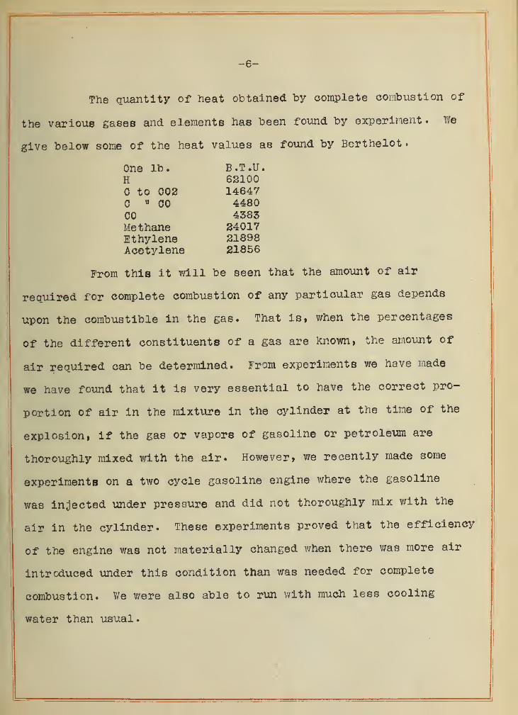
The quantity of heat obtained by complete combustion of
the various gases and elements has been found by experiment. We
give below some of the heat values as found by Berthelot
.
One lb. B.T.U.H 62100
to 002 14647« 00 4480
00 4383Methane 24017Ethylene 21898Acetylene 21856
From this it v/ill be seen that the amount of air
reqiiired for complete combustion of any particular gas depends
upon the combustible in the gas. That is, when the percentages
of the different constituents of a gas are known, the amount of
air required can be determined. From experiments we have made
we have found that it is very essential to have the correct pro-
portion Of air in the mixtvire in the cylinder at the time of the
explosion, if the gas or vapors of gasoline or petroleum are
thoroughly mixed with the air. However, we recently made some
experiments on a two cycle gasoline engine where the gasoline
was injected under pressure and did not thoroughly mix with the
air in the cylinder. These experiments proved that the efficiency
of the engine v/as not materially changed v/hen there was more air
introduced under this condition than v;as needed for complete
combustion. V/e were also able to run v/ith much less cooling
water than usual
.


SOME POINTS FOR SFPICISNT OPERATION.
There are so iian^^ variables which have to do with the
efficiency of an internal coiabustion engine that it is hard to
say v/hich of these are the most important. It would maXe oijir
thesis too tedious to take up each of these in detail. However,
we v/ish to discuss three or four.
JACKET WATER :-
A great many experiments have been made both in this
country and in Europe to determine the exact effect of the jacK.et
cooling water on the efficiency. A French engineer has recently
made tests in which he found that a saving of 7fo in gas con-
sujaption per brake H.P. hour v/as made by raising the temperature
of the :'acket cooling water from 140 • to 165 • F. We made ^ome
experiments a few years ago on a 25 H.P, single cylinder four-
cycle engine and foijind that we effected a saving of lOfo by raising
the temperature of the jacket w-iter from 60* to 145 • F. We
carried this teiaperatur© to as high as 200* F, without any serious
effect on the working parts of the engine, and thereby increased
the saving in gas consumption 19.7^o over cooling water at 60 • P.
It is very difficult to say the exact temperature at \vhioh cooling
water should be run for different sise engines, as it varies
largely v/ith the size and design, but it can easily be determined
for any particular engine. We have found that the installation
of thermostatic control valves on the jacket water outlet de-
creases the fuel consumption materially.


COMPRSSSION:-
One of the important things neoesRary to obtain the
pov/er and econom:' in a gas engine is the amount of compression
carried by the engine. The degree of compression has had a
growth from lbs. in the early engines to the present high
compression engines. It has been found that the pressure im-
mediatel3'' after the explosion in a gas or gasoline engine is
approximately three to four tidies the pressure prior to ignition.
It might be thought on accoimt of this that the compression
could be raised to an indefinite amount. However, it is not
practical to compress the gases above certain well defined limits.
With gasoline vapor and air the compression cannot be safely
raised above 85 lbs. gauge to the square inch, and it will be
found that more regiUsur explosions will be obtained by not raising
this pressure to over 75 lbs.
For natural gas of about 900 B.T.U. zhe compression
pressure laay be from 110 lbs. to 130 lbs., while with producer or
Blast Furnace gas the compression pressure ma^'' be from 150 lbs.
to 200 lbs. 'Vith crude oil the compression pressure may be from
250 to 300 lbs.
SP55D: --
The speed of the engine plays no small part in its
efficiency. In an experimental investigation of a gas engine
under variable piston speeds it v/as found that the useful effect
increases with the velocity of the piston, that is, the more
rapid the expansion of the burning gases, the greater the ef-
ficiency obtained. It was found that an engine running on a


-10-
raixture of one volmie of gas to 6^ voliunes of air, with a piston
speed of 5.5 ft. per second, v/as three times as efficient as when
the piston speed was increased to 14 ft. per second. (Hiscox)
IGNITIQN:-
The means of firing the charges in explosive motors has
developed from the open flaiae and slide valve type of the earlier
engines to the hot tube and electric ignition of the present types.
The successful operation of the explosive motor depends very much
upon the perfection of the ignition mechanism. The hot tube
ignition gave very fair results v/hen the tubes were renewed at
short intervals, but if the tubes were allowed to run very long
at a time, they became oxidized and did not readily fire the charge.
It v/ill also be seen that with hot tube ignition the time of
igniting is largely dependent on the temperature of tube and the
degree of compression, so that the hotter the tube or the higher
the compression, the earlier the ignition.
The different electrical devices are many and varied
but there are tv/o general types, the spark and the make and
break. With the jump spark an induction coil is employed, the
points of the igniter remaining at a constant distance apart, the
time of the spark being controlled by external contact points.
In the make and break igniters the points are mechanically sep-
arated, either by external or internal means. With either of the
electric devices the time of ignition may be changed to different
points of the stroke without regard to the amount of compression
carried by the engine
.


-11-
The tlr.ie of ignition is a very important factor in the
economical operation of the gas engine. Different authorities
vary convsiderably as to the proper tirae of igniting the charge,
but it is not uncommon to find engines igniting 25 • ahead of
center. Engines using gas of low hydrogen sometimes are fired
40 • ahead of center.
It seems to us that the time is at hand for engine
builders to adopt a S3^stem of ignition on all engines ivhere the
point of ignition nay be advanced cr retarded while the engine is
in operation.
AIR INLET:-
The size of the air inlet is a subject which is receiving
careful attention at the present time. Recently we have made a
nijmber of experiments along this line, and found that in some makes
of engines we v/ere able to effect a saving by decreasing the air
inlet, the gas inlet remaining the same, v/hile in others it was
necessary to increase the air inlet. It would seem at present
that it would be quite desirable to have an air inlet, the area
of which could be readily changed.
REGULATION GUARANTEES :
-
The regulation of gas engines is as yet very poor com-
pared to that of the steam engine, water wheel, or steam turbine.
We sometimes read in catalogs that "Our engine is the only one on
the market that will run an electric light plant succesBfull3'"'
.
Such a statement as this is without meaning, and a guarantee
based on such an assertion is absolutely worthless. Our at-
tention was called not along ago to one iiaker who claimed that


-13-j
his engine would regulate ^vithin ifo of norraal between 504 load
and fiill load. Aiiother iiaker says he is willing to guarantee his
engines of 100 H.P. to successful 13'- operate alternators in par-
allel, but vmen such guarantees are given we oay be assured that
the maker has left some loop hole through which he can escape the|
penalties.
The guarantees of fuel consuraption made by soi'ie makers
are just as radical as those of regulation, ^'or instance, one
maker will guarantee his engine to develop an Indicated H.P. on a
certain mimber of cubic feet of city gas. As an illustration of
this, one maker guarantees to deliver an Indicated H.P. on 17 cu. ft
of coal gas, or 15 cu. ft. of natural gas. This kind of a guar-
antee is very unsatisfactory from the point of view of the
ordinary operator of gas engines. The guarantee on fuel con-
sumption should be based on British thermal units per brake H.P.
These are quantities which can be definitely determined, and over
which no dispute is liable to arise.


-18-
GAS PRODUCERS & PRODUCER GAS.
HISTORY:-
Recent developraents indicate very positively'' that two
factors will be of great importance in the econoraioal production
of power for manufactiiring and transportation purposes. These
two factors are the replacing to a raarked extent of the steam
boiler and steara engine hy producer gas plants, with their
accompanying internal combustion engines and the centralization
of pov/er production and distribution. In view of the possibility
of the gas producer and gas engine displacing the steara engine,
the U.S. Government made special provisions for producer gas
tests at its fuel testing plant installed in connection v/ith the
Exposition at St. Louis. These tests have furnished valuable
data on the relative consumption of coal per H.P. hour when used
by a steara plant and by a gas plant.
The credit of being the first to design a practical gas
producer belongs undoubtedly to MM. Thomas and Laurent, v/ho be-
tween 1838 and 1841 constructed a gas generating furnace in;
v/hich many improvements were anticipated. Air from a blower was
atlmitted frora the bottom of the furnace and the decomposition of
the air was assisted by the injection of superheated steam. There
are a number of distinguished engineers who must also be mentioned
in connection with the early history of producer gas generators.
The first pressure generators were introduced by Dowson of London,
and while he installed a great many of these producers they were
of a very complicated nature. Hov/ever, these complications have


-14-
been overcorae largely by later deslsns. For a long time the narae
Dowson was almost s^monyinous svlth producer gas» His producers
v;ere of such design as to necessitate the use of anthracite coal
or coke.
Benier and A. Taylor, two French engineers, nade sorie
very praiseworthy, although net iruaediately successful attempts
to simplify the manufacture of producer gas. Along with the najae
of Dowson that of Dr. Mond xiust be mentioned as being one who
took an active part In the vigorous development of further forms
of producers. While Dowson worked along the line of an anth-
racite coal producer. Dr. Mond worked along the line of a bit-
uminous coal producer.
The name Siemens is also connected with the early
history of the producer and it was he who developed the regener-
ative f^irnaces in 1857, sijch as v/ere employed in the process of
steel making.
The rapid advance of the large gas engine has been made
possible by improvements in the production of cheap gas directly
from fuel through the aid of the gas producer. An early form
of producer introduced in Europe and now in very general use
both abroad and at home, is Known as the suction producer. It
received this name from the fact that the engine develops its
charge of gas in the producer by means of its OT«m suction stroke.
As far as known, the first suction producer operated in the
United States was installed in 1903, although producers of other


-15-
types were tried, in this coiintry as early as 1896.
The general requirement of a gas engine fuel is that it
must readily mix with air to form a combustible air or vapor. It
must also burn with little or no residue. The latter requirement
is not met by the solid fuels such as powdered coal for instance.
A great many unsuccessful attempts have been made to use powdered
coal, but the ash residue soon seriously interferes with the
operation of the engine. For this reason the necessity of having
a gas producer which would simpl^'' and economically convert solid
combustible matter into a gaseous state has been strongly re-
sponsible for the development of the suction gas producer.
A serious limitation to the utility of the suction
producer has been the fact that owing to the manner cf generating
the gas, no tarry fuels could be used. This prevented the use of
bituminous coal, lignites, peats and other light fuels. The fuels
in most common use for producers of this kind, are charcoal, coke
and anthracite coal. However, there is good reason to believe
that with the experiments going on at the present time, we m,ay
shortly expect a suction producer v;hich can be operated success-
fully on bituminous coal. In the pressure producer the gas is
generated under slight pressure, due to the introduction of an
air and steam blast, and stored in a holder until it is required
for the engine. As the gas may thus be stored before passing
to the engine, and as it is produced under pressure, tar and
other impurities may be removed from it by devices that permit


-16-
the use of bituminous coal and lignites.
DISCUSSION OF PRINCIPLES.
The various points to consider in disciissing the sub;]eot
of producers can best be understood by a description of the
operation involved.
A fire is built on the grate at the bottom of the pro-
ducer, until we have a depth corresponding to the depth of our
producer, all the time air is blown through openings in the grate,
up through the m.ass of fuel; this may be accomplished by means of
a blower, or by a suction exhauster, 'or the fuel may be raised
to incandescence by means of a natural draught, but whatever the
means employed, the ob;]ect aimed at is the same, the only differ-
ence would be the amount of gas produced in a given time, and
naturally the greater amount of air, the greater the voiLime of
gas produced, with its attendant rapid increase in temperature.
Take for example a fuel of anthracite or coke, the product from
either fuel if steam is passed up through the grate, villi be
composed of carbonic acid, carbon monoxide, hydrogen and nitrogen.
Having our fuel raised to a reasonably high temperature
throughout its mass, we now begin the manufacture of producer
gas by passing air only through the grate in the bottom of the
producer. The first reaction that takes place, if air alone is
used, either by suction or under pressure, by blov/ing in, is as
follows; Air is composed of 25 parts of oxygen and 77 parts
nitrogen by weight; nitrogen is inert, does not burn and does
not assist combustion, in fact is useless; oxygen is a supporter


-17-
Of combustion. As the air comes in contact v;ith the hot fuel the
oxygen of the air combines with the carbon of the fuel and bvirns
to form carbonic acid gas thus; 0-hB. 0- 00> . The nitrogen of the
atmosphere simply retards combustion and tends to smother the fire.
As the carbonic acid gas mixed v/ith inert nitrogen
passes up through the mass of hot fuel, it is decomposed into
carbon monoxide thus 00^,+ C 200
.
Our first product, carbonic acid, is not combustible,
but by decomposing it into carbon monoxide, we obtain a com-
bustible product . If steam is passed into the producer then our
product will be composed of hydrogen in addition to the above
gases; in fact water, in the form of steam aids the decomposition
of the previously formed carbonic acid; v;ater is composed of the
elements hydrogen and oxygen. Hydrogen is combustible and will
burn. The following equation shows hov/ water is decomposed in
contact with incandescent carbon: H^O-h 0- C0-f-2H.
By this it ¥7ill be seen that producer gas consists of
useful as well as inert substances. Take for instance, the com-
bustible ingredients found in producer gas, which is made from
coke or antliraoite. In this gas will be foimd carbon monoxide,
hydrogen and nitrogen, while in addition to these if bituminous
coal is used, we would have compounds of carbon aiid hydrogen
knovm as carbureted hydrogen or marsh gas, and some traces of
heavy hydro-carbons, the proportion depending on the composition


-18-
of the coal and the method and temperatiire at which the producer
was run. With bitiiininous coals the higher the temperature the
greater will be the volume of lighter hydro-carbon gases produced.
Here wa come in contact with one of the difficulties in the pro-
duction of producer gas from soft coal. The tar and heavy hydro-
carbons pass off and condense in the outlet pipes. They eventually
leave a thick deposit of pitch, which combining with the dust and
soot carried over from the producer, complete a mixture which in
time causes the pipe to become stopped up. Many devices have
been invented to overcome this trouble, but there is one general
principle which must be carried out, and the sooner it is carried
out the greater is the success, that is, the heavy tarry com-
pounds must be decomposed. This can only be done by submitting
them to a high temperature before leaving the producer. In
suction producers a groat deal of trouble is encountered by
fusing the ash when the temperature is raised high enough to
decompose these tarry compounds.
ESSENTIAL POINTS TO CONSIDER.
There are several important points to consider in the
successful operation of a producer and we wish to mention some
at this time, especially in connection with the suction producer.
LQGATION IN THE PLANT:-
The gas generator should be so placed, where possible,
that it is easily accessible from all sides. V/ith a producer thus
located the operator can easily stoke the fire and leave it in a
uniform condition. Operators often make the mistake of stoking
unevenly and too often, especially where they can get at the fire


-19-
from but two sides of the producer. Uneven stoking, either from
the sides or from the top, in a producer which is working up to,
or near its capacity, is very liable to cause fusing of the ash.
This in time will scaffold from the sides of the generator until
it is completely closed up.
AIR SUPPLY :-
Another important point is to see that there is a
thorough and equal distribution of air through the masses of coal
so as to prevent it burning in holes. This id accomplished by
many varied forms of grate, each manufacturer generally having
this part of his generator patented. In some producers the water
seal is used and the steam from the hot ashes keeps the grate cool
and renders the clinkers soft and pliable.
STEAM SUPPLY:-
The steam is usually supplied from a vaporizer or boiler
which is heated by means of the hot gases d^st as they leave the
generator on their way to the scrubber. It is very important that
this steam supply be so arranged as to be under the control of the
operator. The steam is usually generated under no pressure, and
in many of the installations the means of regulating the height of
the water is a simple overflow box located conveniently near the
generator, so that it is at all times in sight of the operator.
STARTING THE PRODUOER:-
V/here producers are used in intermittent service, such
for example, as day load in industrial or manufacturing plants, it
is necessary to bring the generator up to a producing state in
the morning before starting the engine. It is well to do this


-20-
by means of a suction exhauster instead of by a pressure blower*
as in this case the exhauster ptits on the producer the same kind
of service required by the engine and delivers the gases through an
exhaust pipe to the outside air. With the pressure blower v/hich
is sometimes used there is a liability of the gases leaking into
the engine room. We have known a number of cases where this has
been the cause of sickness and loss of life, of persons employed
in the engine room, as the CO gas is quite poisonous. All ash
and cinders should be removed from the generator before the
exhauster is started.
YIELD OF GAS:-
Regarding the yield of gas, it must be remembered that
it is impossible for a gas producer to create either heat or matter
It simply changes the form of matter but does not increase or
create any more power than was originally present in the coal
.
For example, if one pound of anthracite coal contains 14,000 heat
units, it is impossible to get 14,001 heat units from this coalI,
by means of a producer. The yield of gas is based on the grade of
coal and the heat units per cubic foot of gas. For example, it
makes no difference In the yield of gas if one producer will pro-
duce 80 cu. ft. of gas per pound of coal, while another will pro-
duce only 40 ou. ft. of gas, both using the same grade of coal,
provided the gas from the second producer contains twice as many
heat units per cubic foot, as that of the first producer, although
it might make a difference in the value of the producer to do a
certain vrork.


-21-
BLAST FURNACE GAS ENGINE PLANTAT GARY, IND.
Power engineers have been very much divided in their
opinions as to the reliability of internal combustion engines to
give continuous service. Although there has recently been a
number of comparatively large sized xinits Installed both in this
country and in Europe, yet it was not until the United States
Steel Co, made their most modern plant almost entirely dependent
upon internal combustion engines for its power, that the whole
world began to realize the reliability of gas engines. We made
an inspection of this blast furnace gas engine plant at the
Indiana Steel Co., Gary, Ind., in order to give here a short
description of it.
The conplete installation consists of three houses,
two for the blowing engines and one for the electric power plant.
The electric power plant contains 17 twin tandem, double acting,
fo^^r-cycle gas engines. Fifteen of these are direct connected to
2000 K.W., three phase, 25 cycle alternators. Two of them are
direct connected to 2000 K.W., 250 volt D.O. generators. Eachi
Of the engines occupy a floor space of approximately 43 x 70 ft.,
and weigh approximately 1,750,000 lbs. each. The cylinders of
the electric engines are 44« in diameter by 54« stroke. The
piston speed when the engines are running normal, is approximately
750 ft. per minute, the rim velocity of the fly-wheel being
approximately 6000 ft. per minute.


-22-
FOUNDATIQNS:-
Owing to the fact that the plant is built on sand it has
been necessary to put very heavy foundations under the buildings
and machinery. Excavations were made in the sand to a depth cor-
responding with the water level of Lake Michigan, then a solid
slab of concrete 6 ft. thick was put under the entire building.
The walls of the binlding and the foundations for the engines rest
on this slab, no piling at all being used.
aAS:-
The gas is generated In the blast furnaces, fi"om there
it passes to the primary washers, which are composed of vertical
cylinders having spiral baffle plates. The gas enters at the top
of the primary washer, passing out near the bottom. From here it
goes to the Choppy Washer. This washer is filled with wooden
grids, the gas passing upward through these grids against a
spray of water. From here it goes to the Thiessen Washers. These
v/ashers are rotated by means of direct connected motors. The gas
passes through the washer and passing out at the top goes directly
to the gas holders. The gas holders are weighted for S-J-" pressure..
The gas in the holder has but .0065 grains of impurity per cubic
foot, v;hich Is cleaner than the ordinary air. For every cubic
foot of air which is blown into the furnace 1-J- cu. ft. of gas is
given off. About 70fo of all the gas generated is saved. Of this,
65fo is available for gas engines, the rest being used in the
furnaces, stoves, etc. The average composition of the gas isCO 26.5002 -11-5H 3*3CH4 ^1


-23-
The rest is made up of nitrogen and moistiore. This gas has a
heating value of 95 to 105 B.T.U. per cubic foot, and as it comes
to the engine has approxiniately 3.3 grains of moisture per cubic
foot
.
ENGINES :-
They have found that the mixture best suited for their
engines is one part of gas to one part of air. The engines are
designed to carry 200# compression when rimning at normal load,
and will develop their rated capacity on gas of 77 B.T.U. per
cubic foot. They are also designed strong enough to carry an
overload equal to that obtained from gas of 110 B.T.U. per cubic
foot. The generators are rated at 2000 K.7/. and are 35° machines.
They are designed to csirry a 50fo overload continuously.
The blov/ing engines operate Slick blowing tubs which
have a capacity of 33,000 cu. ft. of free air per minute per engine.
The pressure carried on the air mains by these blov/ing tubs is
from 15 to 30# per sq. in. The cylinders of the gas engines
operating these blov;ing tubs are 42 x 54" and are rated at 54
revolutions per minute, however, they have successfully operated
these at 70 R.P.M. The jacket cooling water is brought in from
the Lake through a tunnel half a mile long. They have experienced
considerable trouble from fish getting into the cooling water
jackets and stopping circulation, and have found it necessarj''
to install twin strainers to catch these fish. The engines are
lubricated by means of a gravity circulating oil system, the oil


-24-
being stored In tanlcs in the basement. It is pumped into a reser-
voir high enough to give a pressure of about 15# per sq. in. on
the system at the engines. The system holds approximately 25,000
gallons Of oil and is purified by raeans of precipitation and
settling tanks.


SPECIFICATIONS FOR STTCTION OAS PRODUCER PLANT,
These specifj. cat ions are to cover all labor and laaterlal
necessary to install a complete 150 H.P. plant to be operated on
producer gas. The building, sewers, catch basins and floor will
be fiarnished by the building contractor, but this contractor is to
furnish and install the gas producer, cleaning apparatus, holder,
engine, coal conve3^ing raachiner:'', piping and starting apparatus
complete.
This contractor will take the building as he finds it, do
all his o^m cutting, remove the debris resulting from his work,
and turn the plant over to the owner in successful operating con-
dition.
The pa^naents on the contracts will be as follows; on
machinery, one-third of the contract price v/ill be paid upon
delivery of the apparatus at the building, one-third upon erection-
and one-third after 30 '-lays successful operation. On labor, pay-
ments v/ill be jnade from time to time up to Ssfo of the Engineer's
estiiiate of the work done. The balance will be paid in full upon
successful completion of the work.
All v/ork is to be carried on in a workmanlike laanner and in
such a way as to cause no labor troubles with any of the trades
employed on the installation.
The plans attached to and vaade a part of these specifications
are not detail and are intended to show relative locations and
positions. No changes in locations will be permitted unless


-2 6-
written permission is obtained fron the Engineer in charge.
Details necessary for the successful operation of the plant,
v/hether shOTvn or not, will be included in this contract. At the
time of signing the contract the successful bidder raust subialt
such detail plans of the apparatus he proposes to install, as the
Engineer may request.
PATENTS :-
Contractor will inder'mi fj^ the purchaser against an:'- and
all losses v/hich the latter v\ay sustain through suits or otherwise
on account of using any patented article furnished under this
specification, or under any extra that may be allowed hereafter.
Contractor fiirther agrees to defend any suits for infringe
raent of patent in such a manner as to cause minimum inconvenience
to the purchaser.
APPROVED
V/here materials are specified by brand or mal<:er*s name,
bidders will have the privilege of submitting other brands for
approval. No substitutions will be permitted, however, in carrying
out the contract imless such substitute materials have previously
been approved in writing by the purchaser's Engineer, and it is
Txnderstood that such ?naterials, if used, are to be removed by the
contractor without expense to the purchaser, and replaced by the
material specified.
INSPECTION :-
All labor and raaterial furnished under these specifi-
cations are to be at all times subject to the inspection of the
purchaser's Engineer and must be approved b3'' him in writing before
final payment is made.

-27-
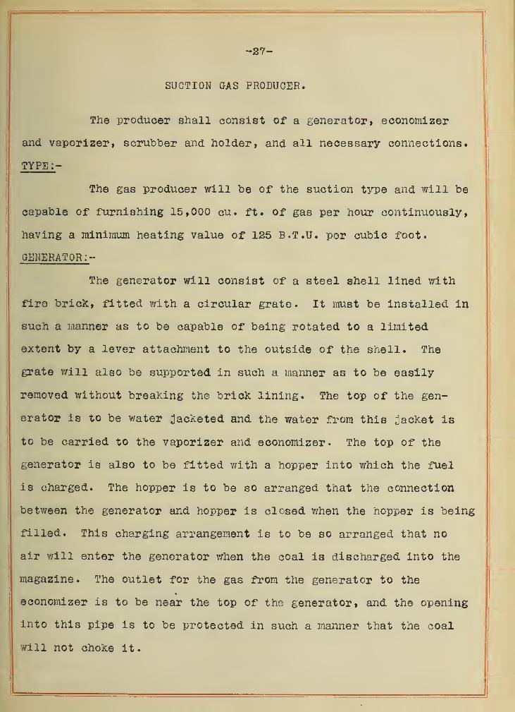
SUCTION GAS PRODUCER.
The producer shall consist of a generator* economizer
and vaporizer, scrubber and holder, and all necessary connections.
TYPE:-
The gas producer will be of the suction type and will be
capable of furnishing 15,000 cu. ft. of gas per hour continuously,
having a mininium heating value of 125 B.T.U. per cubic foot.
GENERATOR:-
The generator will consist of a steel shell lined v/ith
firo brick, fitted v/ith a circular grate. It must be installed in
such a manner as to be capable of being rotated to a limited
extent by a lever attacliment to the outside of the shell. The
grate v/iii also be supported in such a manner as to be easily
removed without breaking the brick lining. The top of the gen-
erator is to be water ^jacketed and the water from this jacket is
to be carried to the vaporizer and economizer. The top of the
generator is also to be fitted v;ith a hopper into v/hich the fuel
is charged. The hopper is to be so arranged that the connection
betv/een the generator and hopper is closed v^hen the hopper is being
filled. This charging arrangement is to be so arranged that no
air will enter the generator when the coal is discharged into the
magazine. The outlet for the gas from the generator to the
economizer is to be near the top of the generator, and the opening
into this pipe is to be protected in such a manner that the coal
will not choke it.


FUEL :
-
The producer shall he bo ^leeigned that it will success-
fully operate on commercial pea anthracite coal of 12,000 3.7.U,
per pound.
SCRUBBER
The shell of the scrubber will be made of steel boiler
plate not less than 3/8" in thickness, the heads to be of 3/8"
steel. The ;joints between the head and the shell are to be caulked
so as to be tight when tested under 10 lbs. of air pressure. There
will be provided two manholes and manhole covers to permit of the
removal of the coke. The coke is to rest on four cast iron grates
supported by angle irons. The first will be placed at least 16"
from the bottom of the scrubber and the others four and eight feet
respectively above the first. The coke is to have a depth of 120"
and is to be wet on the top b3'- means of a v/ater spray consisting
of three nozzles, iiade of l/s" pipe capped and having ten 1/8
"
holes drilled in each. The suppli' of water to these nozzles
will be controlled from a valve placed in the water pipe outside
of the shell of the scrubber within eas3'' reach of the operator.
The scrubber v/iii be provided with an overflow which will drain
to catch basin. This contractor will make all water connections
as well as drains to catch basin.
ECONOMIZER :-
The economizer and vaporizer will be located betv/een
the producer and the scrubber and will be of such diraensions as to
furnish 1.2 lbs. of steam for each pound of coal burned. The
economizer will be of such construction that the incoming air
for supporting the combustion shall pass through the economizer


-29-
and be heated "by the hot gases which also £;enerate the Rtearri, The
ajnount of vapor passing into the bottom of the generator v/iii be
controlled by a control valve within easy access of the operator.
H0LD3R:-
After the gases have parsed through the scrubber they will
be carried into a vertical holder hy a pipe entering from the top,
which shall project downward to within 18" of the bottom of the
holder. The suction pipe to the engine will be taken from the
top of this holder. The capacity of the holder will be equal
to at least one-third the cubic capacity of the scrubber. The
holder v/ill have a 3" water sealed drain to sewer.
SUCTION EXHAUSTER :-
Contractor will install a suction exhauster in the gas
line leading from the holder to the engine, as shown on plan. It
v/111 be so installed that it will deliver the exhausted gas from
the producer to the outside air, and must be so valved as to
close completely when the engine is in operation.
DATA:-
Contractor will f-ornlsh the following data pertaining to
the producer which he proposes to furnish,
Diaraeter of generator.Height of generator.Size of grate in generator.Height of fuel above grate.Capacity of hopper.Diaiieter of scrubber.Height of scrubber.


OAS ETTniNE.
TYPE :-
The engine v/iii be of the four-cycle type, having four
cylinders. It shall he capable of developing 150 actual brake H.P.
at the sheave wheel when operating on producer gas of 125 B.T.U.
GENERAL :-
The engine will be of the vertical self-contained,
enclosed type. The body of the frarae shall form an enclosed case
which contains the crank shaft, riain bearings, (except outboard
bearings), connecting rods and brasses. It shall be oil tight
and shall be so arranged that the lubricating of the laain bearings,
connecting rod bearings and gears shall be accomplished by Means
of a splash oil systera. The lubrication of the cylinders ivill be
accoiaplished by raeans of a raechanical forced feed lubricator.
Cast iron cover plates will be securely bolted to the fraJ'ie on
each side so as to allow easy access to the brasses.
The cylinders will be securely bolted to the cast iron
frame. They are to be of selected close grained charcoal iron.
They are to be v/ater ;]acketed and the water raanifolds shall be so^
arranged as to allow for expansion and contraction without causing
leakage of the water supply'-. There will be installed in the water
outlet of the jacket water a thermostatic control valve which
will be so ad;)usted as to keep the temperature of the exhaust
water practically constsint.
VALVE s: -
The inlet and exhaust valves will be made of steel
forgings and will be so arranged as to be easil:.'' removed for
grinding. The valve seats shall be of cast iron and are to be so


-51-
water jacketed as to Xeep them reasonably cool,
BSARINGS:-
The five nain and two outboard bearings v/ili be lined
with copper hardened babbitt netal. They will be provided with
adiustable taXe-up blocks. The inside bearings are to be so
designed that the oil splashed by the splash pins in the crank
brass bolts will properly lubricate therru The outboard bearings
v/ill be ring oiling, •
'
CRANK SHAFT :-
The crank shaft will be in one piece of forged Open
Hearth steel. It v/ill be finished all over.
CONNECTING RODS:- ;
The connecting rods are to be of forged Open Hearth steel
finsihed all over and bearings are to be of phosphor bronze.
SPSSD:-
The speed will be 275 R.P.M.
GOVSRNOR:-
The governor will be of the throttling tjrpe and will be
ad;Justed so as to raaintain a speed regiAlation within 2</o from no
load to full load, when the load is gradually applied,
FLY-WHEELS :-
There v/ill be two fl3''-wheels 76" in diavaeter. They
will be properly fitted and keyed to the irank shaft. The right
hand one, as shown on plan, will be a machine fi-nished sheave
wheel having 12 grooves of proper shape to take l,l/8" hemp rope.
The left hand v/heel will have cro^vned face.


-33-
ignition:-
The engine is to be equipped with electric igniters of
the nake and break t^rpe, with platinujn points. The external
arrange! lent is to be such that the tirae of ignition may be changed
while running. Current for the igniters ^^vill be fLirnished by a
Bosch laagnsto. There will also be fijirnished a set of twelve large
size clvy cells connected fo-or in series > the throe series con-
nected in iiultiple.
COOLING TANK:-
The contractor is to furnish and install a cooling water
tank of not less than 3000 gallons capacit!'', the water to be
supplied to this tank through an autoraatio float valve and cir-
culation to be insured by raeans of a rotor pwap installed in the
line to the cylinders. This pwap will be installed v/ith a valved
by-pass
.
STARTING DSVICS:-
There is to be fijrnished a compressed air starting
device consisting of an air compressor belted to a 10 H.P.
vertical gasoline engine rimning at a speed of 300 R.P.M. The
compressor must have automatic unloading device, and raust be
capable of filling the tanks with air at 150 lbs. gage pressure
in 30 minutes. The compressed air is to be stored in three tanks
of not less than 20 cu. ft. each and are to be so arranged that
any one or all of the tanks can be used at one time.
FOUNDATION TEMPLATE, -^TC.
This contractor will furnish a fo^indation template,
bolts^ anchors and bolt sleeves.


-33-
0P5RAT0R:-
The contractor shall fnrnlsh, without cost to the
purchaser, a competent operator for a period of ten consecutive
days after the plant has been turned over to the p^orchaser, to
Instruct the purchaser's engineer.
SHAFTING, PULLSYS & BSLTS:-
The shafting for the coal elevator leg will he l,15/l6"
cold rolled steel. The hangers will be cast iron inverted hangers
with ad;iustable ring oiled bearings, and will be supported from
the steel roof trusses on substantial frame work installed by this
contractor. All belts, except the rope drive to the mill, will
be oak tanned light double and will be furnished and installed by
this contractor.
GUARANTEE :-
Contractor will guarantee all apparatus furnished under
this contract to be free from all inherent defects and vd.ll re-
place free of charge any part failing on account of work'aanship
or material, within one year after the acceptance of the plant.
TESTS :-
The purchaser shall have the right to run such tests
for thirty days after the plant is turned over by the contractor,
as he Y'lay deem necessary'' to ascertain whether all contracts have
been properly fulfilled. At the expiration of thirty days suc-
cessful operation and the proper fulfillment of all contracts,
the pijirchaser shall give to the contractor a letter of acceptance*
Pinal payment shall then be made in full.

-34-
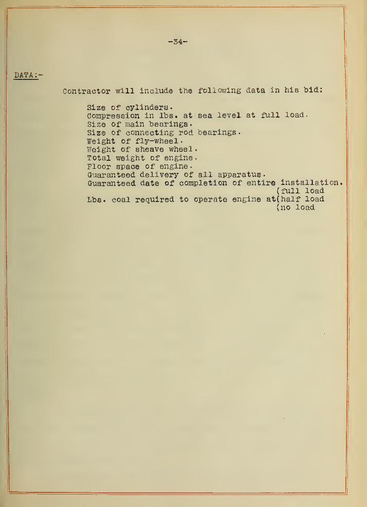
DATA:-
Contractor will include the follov'/ing data in his bid:
Size of cylinders.Compression in lbs. at sea level at full load.Size of main bearings.Size of connecting rod bearings.Weight of fly-v/heel
.
Weight of sheave wheel
•
Total v/eight of engine
.
Floor space of engine.Guaranteed delivery of all apparatus
.
Guaranteed date of completion of entire installation.(full load
Lbs. coal required to operate engine at (half load(no load


-35-
MISOELLANEOUS SPECIFICATIONS.
PIPING.
All pipe and fittings will be of standard weight and only
new material is to be used. All water piping is to be riin v/ith due
allowance for drainage. All pipe must be well supported by sub-
stantial hangers. The Joints are to be made tight v/ithout the use
of white or red lead.
GAS PIPING:-
The gas piping will be run as shown on drawing. There
will be two pipes passing through the roof to the outside air, one
to be taken off at the by-pass valve between the economizer and
scrubber and to be so arranged that when the producer is temporarily
shut down, with the fire going, the gas produced will pass out
through this pipe to the air. The other pipe will be the dis-
charge from the suction exhauster. The exhaust from the engine
will be carried through the side of the building and then upward.
It will end ;]ust above the roof and must be securely fastened by
1/2" round iron bands securely bolted to the building wall. The
bottom elbow will have a 3/4" drain cock. All gas piping will have
flanged fittings, and blank flange Tees must be so placed that the
gas piping can be readily cleaned.
VALVES :-
The valves in the water and air lines will be brass
rough body Jenkins disk and will have nickel trirnmings and wood
v;heelB. The valves in the gas lines will be iron body, brass
trimmed flanged gate valves.
All water and air connections will be made of galvanized pipe.


-36-
OOVERING *
This contractor will cover all cold water piping with l"
of hair felt covering. This covering is to be protected by canvas
;]acK:et. That portion of the exhaust piping v/hioh is between the
engine and the point \vhere the pipe passes out of the engine
room will be covered with 1" Vitribestos covering held in place
by metal bands.
COAL CONVEYING MAOHINSRY .
This contractor will furnish and install one bucket
elevator, one receiving hopper and one coal bunker.
RECEIVING HOPPER
The receiving hopper will be made of 3/8" boiler plate
securely riveted together, 3 '-6" vn.de by 5'-0» long by 3 '-6" high.
It will have a sloping bottom so that the coal will discharge
by gravity into the receiving boot. One side of this hopper v/ill
be hinged so that it v/ill open outward through an opening pro-
vided in the wall. This vrlll act as a receiving shoot for un-
loading the coal from the wagon. This receiving hopper is to be
securely fastened to the wall by means of a 2 x 3/8« Iron band
passing around the top edge of the hopper and bolted to the wall
with two 3/4" bolts. It will also be supported by substantial
floor supports.
COAL BUNKER :-
Contractor will install a coal bunker at such a height
that the coal will discharge by gravity into the hopper of the


-37-
producer. This bimker will be 7 ft. wide, by 10 ft. long by
4 ft. deep and will be made of s/s" boiler plate securely riveted
together. This ooal. blinker vrLll be supported on 10»', 25# "I"
beams one end of which is imbedded in the wall, the other end being
supported by a l-$-" rod suspended from the roof truss. The side
of the bunker next to the producer v;ill be supported on a
4 X 4 X 3/8" angle iron securely riveted to the side of the bunker
and resting on the 10" »I" beam. The discharge spout into the
hopper of the producer v/ill have a closing valve installed in it.
ELEVATOR LEa:-
This contractor will furnish an approved t3rpe of elevator
leg having 4x6" steel elevator buckets carried on sprocket
chains. These buckets are to be spaced approximately 24" apart.
The boot is to be made of #10 steel, the head to be of #14 steel
and will have three doors conveniently placed in the casing, one
to be near the bottom, one near the middle and one near the top.
The driving pulley ^vill be in the head and the take-up in the boot.
The drive will be from a line shaft and the drive pulleys will be
tight and loose, but the belt shifter will be so arranged as to
be operated from the floor by means of chains extending down the
side of the elevator leg.
»


58-
FQTJNDATIONS .
All foundations will be located as shown on ciraTd.ng,
and raust be laid out hy center lines. The foiindations will be
built of concrete in the proportions of 1-3-5. The broken stone
must pass through a If" ring and rest on a l/s" ring.
The ceraent and sand are to be thoroughly mixed dry, tire
stone is then to be added and thoroughly mixed. The concrete
must be thoroughly tanped with a tamper weighing at least one
pound per square inch of tai'iping face. The diraensions of the
foundations are shovm on drawing, but the final dimensions must
be approved in writing after the contracts for machinery have
been let and template drawings of apparatus have been approved
by the :^ngineer.
All parts of the foundations which show above the floor
or aro-ijuid the bases of the machines must be finished with a smooth
coat of cement, applied v/hile the foundation is still wet.
PAINTING.
All machinery will have tv/o coats of metallic filler
applied before shipment, this filler to be r^ibbed ciomi to a smooth
finish. After the machinery is erected it will be thoroughly
cleaned with gasoline and then painted as follows:
The shell of the producer and the economizer will be
painted with a black metallic paint suitable to stand high tem-
peratures. The scrubber, holder and cooling water tank are to be
painted with a black enamel paint suitable to \>rit>istand moisture.
The engine will be painted with two coats of flat maroon


-59-
color and. then have two coats of hard (ir^'-ing varnlBh, at least
twenty-four hours to be allov/ed between the application of the
different coats so as to be sure that the former is thoroughl:?- dry.
All piping and pipe covering, also the coal bunker,
elevator leg and receiving hopper will be painted with a black
elastic raetallio paint.
The sraall gasoline engine, air corapressor, suction ex-
hauster and air tanks are to be painted with a raaroon metallic
flat color and given two coats of varnish.
All valves will be painted with a raaroon enamel.


4/.
FLOOR LIN£
I
15
£L£l//fTJOA/
SCRUBB£H


4-3
/6-0"
I\
^ OF ^//aFT,
6-0 n£fP
1
1 36HHP
'0-
COOLING T/iNK
Z4 DEEP.
-7-6
-I
24 DEEP
a'-ro
roo/vmr/o/v PLffr/.